EP1433642A1 - Dispositif de commande pour un groupe motopropulseur hybride et méthode de commande associée - Google Patents
Dispositif de commande pour un groupe motopropulseur hybride et méthode de commande associée Download PDFInfo
- Publication number
- EP1433642A1 EP1433642A1 EP03029735A EP03029735A EP1433642A1 EP 1433642 A1 EP1433642 A1 EP 1433642A1 EP 03029735 A EP03029735 A EP 03029735A EP 03029735 A EP03029735 A EP 03029735A EP 1433642 A1 EP1433642 A1 EP 1433642A1
- Authority
- EP
- European Patent Office
- Prior art keywords
- torque
- prime mover
- drive unit
- energy
- hybrid drive
- Prior art date
- Legal status (The legal status is an assumption and is not a legal conclusion. Google has not performed a legal analysis and makes no representation as to the accuracy of the status listed.)
- Granted
Links
Images


Classifications
-
- B—PERFORMING OPERATIONS; TRANSPORTING
- B60—VEHICLES IN GENERAL
- B60W—CONJOINT CONTROL OF VEHICLE SUB-UNITS OF DIFFERENT TYPE OR DIFFERENT FUNCTION; CONTROL SYSTEMS SPECIALLY ADAPTED FOR HYBRID VEHICLES; ROAD VEHICLE DRIVE CONTROL SYSTEMS FOR PURPOSES NOT RELATED TO THE CONTROL OF A PARTICULAR SUB-UNIT
- B60W20/00—Control systems specially adapted for hybrid vehicles
- B60W20/40—Controlling the engagement or disengagement of prime movers, e.g. for transition between prime movers
-
- B—PERFORMING OPERATIONS; TRANSPORTING
- B60—VEHICLES IN GENERAL
- B60K—ARRANGEMENT OR MOUNTING OF PROPULSION UNITS OR OF TRANSMISSIONS IN VEHICLES; ARRANGEMENT OR MOUNTING OF PLURAL DIVERSE PRIME-MOVERS IN VEHICLES; AUXILIARY DRIVES FOR VEHICLES; INSTRUMENTATION OR DASHBOARDS FOR VEHICLES; ARRANGEMENTS IN CONNECTION WITH COOLING, AIR INTAKE, GAS EXHAUST OR FUEL SUPPLY OF PROPULSION UNITS IN VEHICLES
- B60K6/00—Arrangement or mounting of plural diverse prime-movers for mutual or common propulsion, e.g. hybrid propulsion systems comprising electric motors and internal combustion engines ; Control systems therefor, i.e. systems controlling two or more prime movers, or controlling one of these prime movers and any of the transmission, drive or drive units Informative references: mechanical gearings with secondary electric drive F16H3/72; arrangements for handling mechanical energy structurally associated with the dynamo-electric machine H02K7/00; machines comprising structurally interrelated motor and generator parts H02K51/00; dynamo-electric machines not otherwise provided for in H02K see H02K99/00
- B60K6/20—Arrangement or mounting of plural diverse prime-movers for mutual or common propulsion, e.g. hybrid propulsion systems comprising electric motors and internal combustion engines ; Control systems therefor, i.e. systems controlling two or more prime movers, or controlling one of these prime movers and any of the transmission, drive or drive units Informative references: mechanical gearings with secondary electric drive F16H3/72; arrangements for handling mechanical energy structurally associated with the dynamo-electric machine H02K7/00; machines comprising structurally interrelated motor and generator parts H02K51/00; dynamo-electric machines not otherwise provided for in H02K see H02K99/00 the prime-movers consisting of electric motors and internal combustion engines, e.g. HEVs
- B60K6/22—Arrangement or mounting of plural diverse prime-movers for mutual or common propulsion, e.g. hybrid propulsion systems comprising electric motors and internal combustion engines ; Control systems therefor, i.e. systems controlling two or more prime movers, or controlling one of these prime movers and any of the transmission, drive or drive units Informative references: mechanical gearings with secondary electric drive F16H3/72; arrangements for handling mechanical energy structurally associated with the dynamo-electric machine H02K7/00; machines comprising structurally interrelated motor and generator parts H02K51/00; dynamo-electric machines not otherwise provided for in H02K see H02K99/00 the prime-movers consisting of electric motors and internal combustion engines, e.g. HEVs characterised by apparatus, components or means specially adapted for HEVs
- B60K6/36—Arrangement or mounting of plural diverse prime-movers for mutual or common propulsion, e.g. hybrid propulsion systems comprising electric motors and internal combustion engines ; Control systems therefor, i.e. systems controlling two or more prime movers, or controlling one of these prime movers and any of the transmission, drive or drive units Informative references: mechanical gearings with secondary electric drive F16H3/72; arrangements for handling mechanical energy structurally associated with the dynamo-electric machine H02K7/00; machines comprising structurally interrelated motor and generator parts H02K51/00; dynamo-electric machines not otherwise provided for in H02K see H02K99/00 the prime-movers consisting of electric motors and internal combustion engines, e.g. HEVs characterised by apparatus, components or means specially adapted for HEVs characterised by the transmission gearings
- B60K6/365—Arrangement or mounting of plural diverse prime-movers for mutual or common propulsion, e.g. hybrid propulsion systems comprising electric motors and internal combustion engines ; Control systems therefor, i.e. systems controlling two or more prime movers, or controlling one of these prime movers and any of the transmission, drive or drive units Informative references: mechanical gearings with secondary electric drive F16H3/72; arrangements for handling mechanical energy structurally associated with the dynamo-electric machine H02K7/00; machines comprising structurally interrelated motor and generator parts H02K51/00; dynamo-electric machines not otherwise provided for in H02K see H02K99/00 the prime-movers consisting of electric motors and internal combustion engines, e.g. HEVs characterised by apparatus, components or means specially adapted for HEVs characterised by the transmission gearings with the gears having orbital motion
-
- B—PERFORMING OPERATIONS; TRANSPORTING
- B60—VEHICLES IN GENERAL
- B60K—ARRANGEMENT OR MOUNTING OF PROPULSION UNITS OR OF TRANSMISSIONS IN VEHICLES; ARRANGEMENT OR MOUNTING OF PLURAL DIVERSE PRIME-MOVERS IN VEHICLES; AUXILIARY DRIVES FOR VEHICLES; INSTRUMENTATION OR DASHBOARDS FOR VEHICLES; ARRANGEMENTS IN CONNECTION WITH COOLING, AIR INTAKE, GAS EXHAUST OR FUEL SUPPLY OF PROPULSION UNITS IN VEHICLES
- B60K6/00—Arrangement or mounting of plural diverse prime-movers for mutual or common propulsion, e.g. hybrid propulsion systems comprising electric motors and internal combustion engines ; Control systems therefor, i.e. systems controlling two or more prime movers, or controlling one of these prime movers and any of the transmission, drive or drive units Informative references: mechanical gearings with secondary electric drive F16H3/72; arrangements for handling mechanical energy structurally associated with the dynamo-electric machine H02K7/00; machines comprising structurally interrelated motor and generator parts H02K51/00; dynamo-electric machines not otherwise provided for in H02K see H02K99/00
- B60K6/20—Arrangement or mounting of plural diverse prime-movers for mutual or common propulsion, e.g. hybrid propulsion systems comprising electric motors and internal combustion engines ; Control systems therefor, i.e. systems controlling two or more prime movers, or controlling one of these prime movers and any of the transmission, drive or drive units Informative references: mechanical gearings with secondary electric drive F16H3/72; arrangements for handling mechanical energy structurally associated with the dynamo-electric machine H02K7/00; machines comprising structurally interrelated motor and generator parts H02K51/00; dynamo-electric machines not otherwise provided for in H02K see H02K99/00 the prime-movers consisting of electric motors and internal combustion engines, e.g. HEVs
- B60K6/42—Arrangement or mounting of plural diverse prime-movers for mutual or common propulsion, e.g. hybrid propulsion systems comprising electric motors and internal combustion engines ; Control systems therefor, i.e. systems controlling two or more prime movers, or controlling one of these prime movers and any of the transmission, drive or drive units Informative references: mechanical gearings with secondary electric drive F16H3/72; arrangements for handling mechanical energy structurally associated with the dynamo-electric machine H02K7/00; machines comprising structurally interrelated motor and generator parts H02K51/00; dynamo-electric machines not otherwise provided for in H02K see H02K99/00 the prime-movers consisting of electric motors and internal combustion engines, e.g. HEVs characterised by the architecture of the hybrid electric vehicle
- B60K6/44—Series-parallel type
- B60K6/445—Differential gearing distribution type
-
- B—PERFORMING OPERATIONS; TRANSPORTING
- B60—VEHICLES IN GENERAL
- B60K—ARRANGEMENT OR MOUNTING OF PROPULSION UNITS OR OF TRANSMISSIONS IN VEHICLES; ARRANGEMENT OR MOUNTING OF PLURAL DIVERSE PRIME-MOVERS IN VEHICLES; AUXILIARY DRIVES FOR VEHICLES; INSTRUMENTATION OR DASHBOARDS FOR VEHICLES; ARRANGEMENTS IN CONNECTION WITH COOLING, AIR INTAKE, GAS EXHAUST OR FUEL SUPPLY OF PROPULSION UNITS IN VEHICLES
- B60K6/00—Arrangement or mounting of plural diverse prime-movers for mutual or common propulsion, e.g. hybrid propulsion systems comprising electric motors and internal combustion engines ; Control systems therefor, i.e. systems controlling two or more prime movers, or controlling one of these prime movers and any of the transmission, drive or drive units Informative references: mechanical gearings with secondary electric drive F16H3/72; arrangements for handling mechanical energy structurally associated with the dynamo-electric machine H02K7/00; machines comprising structurally interrelated motor and generator parts H02K51/00; dynamo-electric machines not otherwise provided for in H02K see H02K99/00
- B60K6/20—Arrangement or mounting of plural diverse prime-movers for mutual or common propulsion, e.g. hybrid propulsion systems comprising electric motors and internal combustion engines ; Control systems therefor, i.e. systems controlling two or more prime movers, or controlling one of these prime movers and any of the transmission, drive or drive units Informative references: mechanical gearings with secondary electric drive F16H3/72; arrangements for handling mechanical energy structurally associated with the dynamo-electric machine H02K7/00; machines comprising structurally interrelated motor and generator parts H02K51/00; dynamo-electric machines not otherwise provided for in H02K see H02K99/00 the prime-movers consisting of electric motors and internal combustion engines, e.g. HEVs
- B60K6/42—Arrangement or mounting of plural diverse prime-movers for mutual or common propulsion, e.g. hybrid propulsion systems comprising electric motors and internal combustion engines ; Control systems therefor, i.e. systems controlling two or more prime movers, or controlling one of these prime movers and any of the transmission, drive or drive units Informative references: mechanical gearings with secondary electric drive F16H3/72; arrangements for handling mechanical energy structurally associated with the dynamo-electric machine H02K7/00; machines comprising structurally interrelated motor and generator parts H02K51/00; dynamo-electric machines not otherwise provided for in H02K see H02K99/00 the prime-movers consisting of electric motors and internal combustion engines, e.g. HEVs characterised by the architecture of the hybrid electric vehicle
- B60K6/48—Parallel type
-
- B—PERFORMING OPERATIONS; TRANSPORTING
- B60—VEHICLES IN GENERAL
- B60W—CONJOINT CONTROL OF VEHICLE SUB-UNITS OF DIFFERENT TYPE OR DIFFERENT FUNCTION; CONTROL SYSTEMS SPECIALLY ADAPTED FOR HYBRID VEHICLES; ROAD VEHICLE DRIVE CONTROL SYSTEMS FOR PURPOSES NOT RELATED TO THE CONTROL OF A PARTICULAR SUB-UNIT
- B60W10/00—Conjoint control of vehicle sub-units of different type or different function
- B60W10/04—Conjoint control of vehicle sub-units of different type or different function including control of propulsion units
- B60W10/06—Conjoint control of vehicle sub-units of different type or different function including control of propulsion units including control of combustion engines
-
- B—PERFORMING OPERATIONS; TRANSPORTING
- B60—VEHICLES IN GENERAL
- B60W—CONJOINT CONTROL OF VEHICLE SUB-UNITS OF DIFFERENT TYPE OR DIFFERENT FUNCTION; CONTROL SYSTEMS SPECIALLY ADAPTED FOR HYBRID VEHICLES; ROAD VEHICLE DRIVE CONTROL SYSTEMS FOR PURPOSES NOT RELATED TO THE CONTROL OF A PARTICULAR SUB-UNIT
- B60W10/00—Conjoint control of vehicle sub-units of different type or different function
- B60W10/04—Conjoint control of vehicle sub-units of different type or different function including control of propulsion units
- B60W10/08—Conjoint control of vehicle sub-units of different type or different function including control of propulsion units including control of electric propulsion units, e.g. motors or generators
-
- B—PERFORMING OPERATIONS; TRANSPORTING
- B60—VEHICLES IN GENERAL
- B60W—CONJOINT CONTROL OF VEHICLE SUB-UNITS OF DIFFERENT TYPE OR DIFFERENT FUNCTION; CONTROL SYSTEMS SPECIALLY ADAPTED FOR HYBRID VEHICLES; ROAD VEHICLE DRIVE CONTROL SYSTEMS FOR PURPOSES NOT RELATED TO THE CONTROL OF A PARTICULAR SUB-UNIT
- B60W10/00—Conjoint control of vehicle sub-units of different type or different function
- B60W10/10—Conjoint control of vehicle sub-units of different type or different function including control of change-speed gearings
-
- F—MECHANICAL ENGINEERING; LIGHTING; HEATING; WEAPONS; BLASTING
- F16—ENGINEERING ELEMENTS AND UNITS; GENERAL MEASURES FOR PRODUCING AND MAINTAINING EFFECTIVE FUNCTIONING OF MACHINES OR INSTALLATIONS; THERMAL INSULATION IN GENERAL
- F16H—GEARING
- F16H3/00—Toothed gearings for conveying rotary motion with variable gear ratio or for reversing rotary motion
- F16H3/44—Toothed gearings for conveying rotary motion with variable gear ratio or for reversing rotary motion using gears having orbital motion
- F16H3/72—Toothed gearings for conveying rotary motion with variable gear ratio or for reversing rotary motion using gears having orbital motion with a secondary drive, e.g. regulating motor, in order to vary speed continuously
- F16H3/727—Toothed gearings for conveying rotary motion with variable gear ratio or for reversing rotary motion using gears having orbital motion with a secondary drive, e.g. regulating motor, in order to vary speed continuously with at least two dynamo electric machines for creating an electric power path inside the gearing, e.g. using generator and motor for a variable power torque path
- F16H3/728—Toothed gearings for conveying rotary motion with variable gear ratio or for reversing rotary motion using gears having orbital motion with a secondary drive, e.g. regulating motor, in order to vary speed continuously with at least two dynamo electric machines for creating an electric power path inside the gearing, e.g. using generator and motor for a variable power torque path with means to change ratio in the mechanical gearing
-
- B—PERFORMING OPERATIONS; TRANSPORTING
- B60—VEHICLES IN GENERAL
- B60L—PROPULSION OF ELECTRICALLY-PROPELLED VEHICLES; SUPPLYING ELECTRIC POWER FOR AUXILIARY EQUIPMENT OF ELECTRICALLY-PROPELLED VEHICLES; ELECTRODYNAMIC BRAKE SYSTEMS FOR VEHICLES IN GENERAL; MAGNETIC SUSPENSION OR LEVITATION FOR VEHICLES; MONITORING OPERATING VARIABLES OF ELECTRICALLY-PROPELLED VEHICLES; ELECTRIC SAFETY DEVICES FOR ELECTRICALLY-PROPELLED VEHICLES
- B60L2240/00—Control parameters of input or output; Target parameters
- B60L2240/40—Drive Train control parameters
- B60L2240/42—Drive Train control parameters related to electric machines
- B60L2240/421—Speed
-
- B—PERFORMING OPERATIONS; TRANSPORTING
- B60—VEHICLES IN GENERAL
- B60L—PROPULSION OF ELECTRICALLY-PROPELLED VEHICLES; SUPPLYING ELECTRIC POWER FOR AUXILIARY EQUIPMENT OF ELECTRICALLY-PROPELLED VEHICLES; ELECTRODYNAMIC BRAKE SYSTEMS FOR VEHICLES IN GENERAL; MAGNETIC SUSPENSION OR LEVITATION FOR VEHICLES; MONITORING OPERATING VARIABLES OF ELECTRICALLY-PROPELLED VEHICLES; ELECTRIC SAFETY DEVICES FOR ELECTRICALLY-PROPELLED VEHICLES
- B60L2240/00—Control parameters of input or output; Target parameters
- B60L2240/40—Drive Train control parameters
- B60L2240/42—Drive Train control parameters related to electric machines
- B60L2240/423—Torque
-
- B—PERFORMING OPERATIONS; TRANSPORTING
- B60—VEHICLES IN GENERAL
- B60W—CONJOINT CONTROL OF VEHICLE SUB-UNITS OF DIFFERENT TYPE OR DIFFERENT FUNCTION; CONTROL SYSTEMS SPECIALLY ADAPTED FOR HYBRID VEHICLES; ROAD VEHICLE DRIVE CONTROL SYSTEMS FOR PURPOSES NOT RELATED TO THE CONTROL OF A PARTICULAR SUB-UNIT
- B60W2510/00—Input parameters relating to a particular sub-units
- B60W2510/24—Energy storage means
- B60W2510/242—Energy storage means for electrical energy
- B60W2510/244—Charge state
-
- B—PERFORMING OPERATIONS; TRANSPORTING
- B60—VEHICLES IN GENERAL
- B60W—CONJOINT CONTROL OF VEHICLE SUB-UNITS OF DIFFERENT TYPE OR DIFFERENT FUNCTION; CONTROL SYSTEMS SPECIALLY ADAPTED FOR HYBRID VEHICLES; ROAD VEHICLE DRIVE CONTROL SYSTEMS FOR PURPOSES NOT RELATED TO THE CONTROL OF A PARTICULAR SUB-UNIT
- B60W2710/00—Output or target parameters relating to a particular sub-units
- B60W2710/06—Combustion engines, Gas turbines
-
- B—PERFORMING OPERATIONS; TRANSPORTING
- B60—VEHICLES IN GENERAL
- B60W—CONJOINT CONTROL OF VEHICLE SUB-UNITS OF DIFFERENT TYPE OR DIFFERENT FUNCTION; CONTROL SYSTEMS SPECIALLY ADAPTED FOR HYBRID VEHICLES; ROAD VEHICLE DRIVE CONTROL SYSTEMS FOR PURPOSES NOT RELATED TO THE CONTROL OF A PARTICULAR SUB-UNIT
- B60W2710/00—Output or target parameters relating to a particular sub-units
- B60W2710/08—Electric propulsion units
- B60W2710/081—Speed
-
- B—PERFORMING OPERATIONS; TRANSPORTING
- B60—VEHICLES IN GENERAL
- B60W—CONJOINT CONTROL OF VEHICLE SUB-UNITS OF DIFFERENT TYPE OR DIFFERENT FUNCTION; CONTROL SYSTEMS SPECIALLY ADAPTED FOR HYBRID VEHICLES; ROAD VEHICLE DRIVE CONTROL SYSTEMS FOR PURPOSES NOT RELATED TO THE CONTROL OF A PARTICULAR SUB-UNIT
- B60W2710/00—Output or target parameters relating to a particular sub-units
- B60W2710/08—Electric propulsion units
- B60W2710/083—Torque
-
- F—MECHANICAL ENGINEERING; LIGHTING; HEATING; WEAPONS; BLASTING
- F16—ENGINEERING ELEMENTS AND UNITS; GENERAL MEASURES FOR PRODUCING AND MAINTAINING EFFECTIVE FUNCTIONING OF MACHINES OR INSTALLATIONS; THERMAL INSULATION IN GENERAL
- F16H—GEARING
- F16H37/00—Combinations of mechanical gearings, not provided for in groups F16H1/00 - F16H35/00
- F16H37/02—Combinations of mechanical gearings, not provided for in groups F16H1/00 - F16H35/00 comprising essentially only toothed or friction gearings
- F16H37/06—Combinations of mechanical gearings, not provided for in groups F16H1/00 - F16H35/00 comprising essentially only toothed or friction gearings with a plurality of driving or driven shafts; with arrangements for dividing torque between two or more intermediate shafts
- F16H37/08—Combinations of mechanical gearings, not provided for in groups F16H1/00 - F16H35/00 comprising essentially only toothed or friction gearings with a plurality of driving or driven shafts; with arrangements for dividing torque between two or more intermediate shafts with differential gearing
- F16H37/0833—Combinations of mechanical gearings, not provided for in groups F16H1/00 - F16H35/00 comprising essentially only toothed or friction gearings with a plurality of driving or driven shafts; with arrangements for dividing torque between two or more intermediate shafts with differential gearing with arrangements for dividing torque between two or more intermediate shafts, i.e. with two or more internal power paths
- F16H37/084—Combinations of mechanical gearings, not provided for in groups F16H1/00 - F16H35/00 comprising essentially only toothed or friction gearings with a plurality of driving or driven shafts; with arrangements for dividing torque between two or more intermediate shafts with differential gearing with arrangements for dividing torque between two or more intermediate shafts, i.e. with two or more internal power paths at least one power path being a continuously variable transmission, i.e. CVT
- F16H2037/0866—Power split variators with distributing differentials, with the output of the CVT connected or connectable to the output shaft
- F16H2037/0873—Power split variators with distributing differentials, with the output of the CVT connected or connectable to the output shaft with switching, e.g. to change ranges
-
- Y—GENERAL TAGGING OF NEW TECHNOLOGICAL DEVELOPMENTS; GENERAL TAGGING OF CROSS-SECTIONAL TECHNOLOGIES SPANNING OVER SEVERAL SECTIONS OF THE IPC; TECHNICAL SUBJECTS COVERED BY FORMER USPC CROSS-REFERENCE ART COLLECTIONS [XRACs] AND DIGESTS
- Y02—TECHNOLOGIES OR APPLICATIONS FOR MITIGATION OR ADAPTATION AGAINST CLIMATE CHANGE
- Y02T—CLIMATE CHANGE MITIGATION TECHNOLOGIES RELATED TO TRANSPORTATION
- Y02T10/00—Road transport of goods or passengers
- Y02T10/60—Other road transportation technologies with climate change mitigation effect
- Y02T10/62—Hybrid vehicles
-
- Y—GENERAL TAGGING OF NEW TECHNOLOGICAL DEVELOPMENTS; GENERAL TAGGING OF CROSS-SECTIONAL TECHNOLOGIES SPANNING OVER SEVERAL SECTIONS OF THE IPC; TECHNICAL SUBJECTS COVERED BY FORMER USPC CROSS-REFERENCE ART COLLECTIONS [XRACs] AND DIGESTS
- Y02—TECHNOLOGIES OR APPLICATIONS FOR MITIGATION OR ADAPTATION AGAINST CLIMATE CHANGE
- Y02T—CLIMATE CHANGE MITIGATION TECHNOLOGIES RELATED TO TRANSPORTATION
- Y02T10/00—Road transport of goods or passengers
- Y02T10/60—Other road transportation technologies with climate change mitigation effect
- Y02T10/64—Electric machine technologies in electromobility
Definitions
- This invention relates to a hybrid drive unit provided with two kinds of prime movers as a power source for driving a vehicle, and more particularly, to a control device for a hybrid drive unit, wherein a second prime mover is connected through a transmission to an output member, to which a power is transmitted from a first prime mover.
- JP-A-2002-225578 An example of a control device of hybrid drive unit of this kind is disclosed in JP-A-2002-225578.
- the hybrid drive unit in which an engine and a first motor generator are connected to each other through a synthesizing/distributing mechanism composed of a single pinion type planetary gear mechanism while an output member is connected to the synthesizing/distributing mechanism in a torque transmittable manner, and in which a second motor generator is connected to the output member through a gear shift mechanism.
- a torque synthesized from an output torque of an engine and a torque of the first motor generator in accordance with a gear ratio of the single pinion type planetary gear mechanism appears on an output shaft, and an engine speed can be controlled by the first motor generator. Therefore, it is possible for the engine to be driven for the optimum fuel consumption thereby to improve a fuel consumption of a vehicle.
- the torque can be applied to the output shaft, by generating an electric power (i.e., regeneration of energy) by the first motor generator so as to drive the second motor generator by the electric power generated, when the engine is being driven at the optimum fuel consumption. Therefore, sufficient driving force can be obtained without deteriorating the fuel consumption.
- the torque outputted by the second motor generator can be raised and transmitted to the output shaft, by having an gear ratio to be set by the transmission greater than "1". And in case the gear ratio is reduced (e.g., in case the transmission is set in a high speed stage), a speed of the second motor generator can be decreased so that the second motor generator can be changed into a low power type or a small size type.
- the aforementioned hybrid drive unit is so-called "mechanical distribution type", and the same type of the hybrid drive unit is disclosed in JP-A-2000-295709.
- the unit disclosed in this publication is so constructed as to control the torque of individual motor generator when the gear shift is executed by the transmission.
- JP-A-6-319210 a motor-driven vehicle, in which the output torque of the electric motor is transmitted through the transmission to the output shaft is disclosed in JP-A-6-319210.
- the torque of the electric motor and an apply pressure of the clutch at the shifting time is controlled with judging the situation at the shifting time.
- JP-A-2000-295720 there is described a so-called “series type hybrid drive unit", in which a electric generator is driven by the engine, and in which the electric motor is driven by an electric power generated by the electric generator.
- the gear shift is inhibited in case of driving on a downhill having a gradient steeper than the predetermined value.
- JP-A-9-9414 still moreover, there is described a hybrid drive unit, which is constructed to change a shift point on the basis of a remaining amount SOC (i.e., State of Charge) of the battery. Also, in JP-A-9-233606, there is described a hybrid drive unit, in which the vehicle is driven by the motor with reducing the gear ratio in the case the charging amount SOC remains sufficiently, and in which the vehicle is driven by the engine with greatening the gear ratio in the case the charging amount SOC does not remains sufficiently, on the contrary.
- SOC State of Charge
- this hybrid drive unit is constructed to synthesize the output torque of the engine and the torque of the first motor generator by a planetary gear mechanism, as they are outputted, so that the output shaft torque can be controlled by the first motor generator. Therefore, it is considerable to control the first motor generator thereby to suppress or prevent such torque change at the shifting time by the transmission.
- the torque which acts on the engine as a reaction is changed when, for example, the torque of the first motor generator is changed in order to raise the output shaft torque.
- the engine does not output the torque when the vehicle is driven by the torque of the second motor generator with the engine being halted. Therefore, in case that the torque of the first motor generator is changed so as to suppress the reduction of the output shaft torque at the shifting time in the transmission, the torque to rotate the engine backward may act on the engine.
- first motor generator and second motor generator can perform as either the electric motor or the electric generator, so that the fall of the output shaft torque can be suppressed by controlling the torque of those motor generators variedly at the shifting time in the transmission, when the vehicle runs with using those motor generators.
- the output of an accumulator device such as the battery has to be raised.
- the accumulator device participates in the torque control by the motor generator, but a capacity of the accumulator device is limited. Therefore, the accumulator device cannot drive the motor generator or raise the output torque thereof, when the stored amount of electricity (charging amount) is low. When the stored amount of electricity (charging amount) is almost full, on the contrary, the accumulator device cannot accept the electric power so that the negative torque by the regenerative control of the motor generator cannot be raised.
- This kind of restriction on the control of the motor generator caused by the accumulator device may arise not only from the stored amount of electricity (charging amount), but also from the temperature etc.
- the present invention has been conceived noting the technical problems thus far described and its object is to provide a control device for a hybrid drive unit, which can suppress or prevent shocks as might otherwise accompany the gear shift by the transmission or deterioration in a riding comfort, even if a torque control of any of a first prime mover or a second prime mover capable of applying the torque to the output member is restricted.
- this invention is characterized by the construction, in which the shift point is changed so as to have the torque fluctuation accompanying the gear shift in the transmission small.
- a control device of the hybrid vehicle wherein the output member is connected to the first prime mover, and wherein the second prime mover capable of outputting at least one of a positive torque and a negative torque is connected through the transmission to the output member, comprising: a running restriction judging means or judger for judging that a running control of at least one of the first prime mover and the second prime mover is restricted; and a shift point changing means or changer for changing the shift point, in which a decision of the gear shift in the transmission is to be satisfied when the running restriction judging means or judger judges that the running control is restricted, different from the shift point of the case, in which the running control is not restricted.
- the shift point to decide the gear shift in the transmission is changed in comparison with the case that the running control is not restricted.
- the gear shift is executed in the transmission at the timing appropriate for the torque generated on the output member, and the shocks accompanying the gear shift is lightened or prevented.
- control device further comprising: an energy accumulator for outputting an energy to said first prime mover or second prime mover, or for storing an energy regenerated by any of the prime movers; and wherein said running restriction judging means or judger includes a means or judger for judging the driving restriction on the basis of a condition of the energy accumulator.
- the restriction on said running control is judged on the basis of the condition of the energy accumulator which outputs the energy to any of the prime movers and accepts the energy from any of the prime movers.
- the shift point is changed in case the energy cannot be outputted sufficiently or in case the energy cannot be accepted, so as to lighten or prevent the shocks.
- said drive restriction judging means or judger includes a means or judger for judging the restriction on said running control in case the acceptance capacity of said energy accumulator for energy is smaller than a predetermined value
- said shift point changing means or changer include a means or changer for changing said shit point to the low load side where the demand load for said hybrid vehicle is relatively low, in case the restriction on said running control is judged.
- the restriction on the running control of the prime mover is judged in case the energy accumulator cannot accept the energy regenerated by any of the prime mover, or in case the acceptance of the energy regenerated by any of the prime mover is restricted.
- the shift point to decide the gear shift in the transmission is changed to the relatively low load side.
- the gear shift is executed in the relatively low load state.
- said first prime mover includes a regenerating mechanism for regenerating the energy, and there is further provided an output torque correcting means or corrector for correcting the torque to be transmitted from the first prime mover to said output member to a rising side by changing the regeneration amount of said regenerating mechanism at the shifting time.
- the regeneration of the energy is executed by the regenerating mechanism in the first prime mover at the shifting time in the transmission. And in connection with this, the torque acting on the output member is changed thereby to suppress the change in the torque of the output member at the shifting time.
- the gear shift is executed in the relatively low load state, even if the change in the regenerative torque is small owing to the restriction of the running control of the first prime mover, more specifically, the restriction of the regenerative control of the regenerating mechanism. Therefore, it is possible to suppress or prevent the shocks.
- a control device in which a status of said energy accumulator is at least any of an allowable output amount as an energy amount possible to be outputted by said energy accumulator and an acceptance capacity of said energy accumulator for energy
- said running restriction judging means or judger includes a means or judger for judging the restriction on said running control in case said allowable output amount or acceptance capacity is lower than the predetermined value
- said shift point changing means or changer includes a means or changer for changing said shift point relatively to the low speed side in case the restriction on said running control is judged.
- the gear shift of the case, in which any of the prime mover cannot be sufficiently controlled to suppress the change in the output torque at the shifting time, is caused relatively in the low speed state.
- the time period necessary for the gear shift is shortened, so that the torque change due to the gear shift under the state where any of the prime mover cannot be sufficiently controlled is ended within a short period of time, and the shocks as might otherwise accompany the gear shift becomes hard to be felt or light.
- the gear shift is executed by interchanging the applied/released states of the frictional engagement device, the amount of energy to be absorbed by a frictional member becomes small. This is advantageous to improve the durability.
- a control device in which a status of said energy accumulator is an allowable output amount as an energy amount possible to be outputted by said energy accumulator, in which said running restriction judging means or judger includes a means or judger for judging the restriction on said running control in case said allowable output amount is lower than the predetermined value, and in which said shift point changing means or changer includes a means or changer for changing said shift point to the low load side where the demand load for said hybrid drive unit is relatively small.
- the shift point to decide the gear shift in the transmission is changed relatively to the low load side. Therefore, the change in the output torque as might otherwise accompany the gear shift in the transmission becomes small so that the shocks are hard to occur. Moreover, the change in the output torque is also suppressed by the restricted running control of any of the prime movers. Therefore, shocks are prevented or relaxed also in this respect.
- any of said prime mover is said second prime mover including a drive unit for outputting the torque by receiving the energy from said energy accumulator, and further comprising: a drive controlling means or controller for outputting the torque from said drive unit at the shifting time of the transmission.
- the torque possible to be outputted by the second prime mover at the shifting time becomes small by the restriction on the running control.
- the gear shift is caused in the low load state so that the change in the output torque can be suppressed even if the output torque is a small corrected torque of the second prime mover. As a result, the shocks are prevented or relaxed.
- a control device in which a status of said energy accumulator is at least any of an allowable output amount as an energy amount possible to be outputted by said energy accumulator and an acceptance capacity of said energy accumulator for energy
- said running restriction judging means or judger includes a means or judger for judging the restriction on said running control in case said allowable output amount or acceptance capacity is lower than the predetermined value
- a gear ratio fixing means or device for fixing the gear ratio of said transmission from a starting time of a vehicle having said hybrid drive unit, in case the restriction on said running control is judged.
- the gear ratio at the starting time of the vehicle is kept so as not to cause the gear shift in the transmission. Therefore, the gear shift is not caused in the state where the correction of the torque by any of the prime mover cannot be sufficiently executed, so that the shocks are not deteriorated.
- a control device in which said second prime mover includes an electric motor for outputting a motive power to run the vehicle to said output member with the first prime mover being stopped, and further comprising: a gear shift regulating means or regulator for regulating the gear shift in said transmission when the vehicle is run by the motive power outputted from said electric motor.
- the gear shift in the transmission is regulated, under the state where the vehicle is run by the second prime mover connected through the transmission to the output member. Therefore, the gear shift and the accompanying fluctuation of the torque is not caused, or the fluctuation is regulated, under the state where the output torque cannot be so-called "compensated" by the first prime mover, so that the shocks are suppressed or prevented.
- a control device further comprising: a shifting time torque correcting means or corrector for correcting the torque outputted from said first prime mover at the shifting time in said transmission to the rising side.
- the output torque of the first prime mover is corrected to the rising side at the shifting time in the transmission, under the state where the torque can be outputted and raised by the first prime mover. Therefore, the torque of the output member during the shifting operation in the transmission is compensated by the torque of the first prime mover, and the fall of the output torque at the shifting time or the shock as might otherwise be caused by the fall of the output torque is prevented or suppressed.
- control method of the present invention is executed by the aforementioned individual control device. According to the control method of the invention, therefore, uncomfortable feeling such as the shocks and so on are prevented or suppressed by changing the shift point of the transmission in case the running control of any of the prime mover is restricted.
- the hybrid drive unit or an application target of this invention is mounted on a vehicle, for example.
- the torque of a main prime mover 1 is transmitted to an output member 2, from which the torque is transmitted through a differential 3 to drive wheels 4.
- an assist prime mover 5 which can make a power control to output a driving force for a drive and a regenerative control to recover an energy.
- This assist prime mover 5 is connected through a transmission 6 to the output member 2. Between the assist prime mover 5 and the output member 2, therefore, the transmission torque capacity is increased/decreased according to a gear ratio to be set by the transmission 6.
- This transmission 6 can be constructed to set the gear ratio at "1" or higher. With this construction, at the power running time for the assist prime mover 5 to output the torque, this torque can be outputted to the output member 2 so that the assist prime mover 5 can be made to have a low capacity or a small size. However, it is preferred that the running efficiency of the assist prime mover 5 is kept in a satisfactory state. In case the speed of the output member 2 rises according to the vehicle speed, for example, the gear ratio is lowered to decrease the speed of the assist prime mover 5. In case the speed of the output member 2 drops, on the other hand, the gear ratio may be raised.
- the main prime mover 1 is mainly constructed to include an internal combustion engine (as will be called the “engine") 10, a motor generator (as will be tentatively called the “first motor generator” or “MG 1") 11, and a planetary gear mechanism 12 for synthesizing or distributing the torque between those engine 10 and first motor generator 11.
- the engine 10 is a well-known power unit such as a gasoline engine or a Diesel engine for outputting a power by burning a fuel, and is so constructed that its running state such as the degree of throttle opening (or the air intake amount), the fuel feed amount or the ignition timing can be electrically controlled.
- This control is made by an electronic control unit (E-ECU) 13 composed mainly of a microcomputer, for example.
- the first motor generator 11 is exemplified by a synchronous electric motor and is constructed to function as an electric motor and a dynamo.
- the first motor generator 11 is connected through an inverter 14 with an accumulator device 15 such as a battery.
- an electronic control unit (MG1-ECU) 16 which is composed mainly of a microcomputer.
- the planetary gear mechanism 12 is a well-known one for establishing a differential action with three rotary elements: a sun gear 17 or an external gear; a ring gear 18 or an internal gear arranged concentrically with the sun gear 17; and a carrier 19 holding a pinion gear meshing with those sun gear 17 and ring gear 18 such that the pinion gear may rotate on its axis and revolve around the carrier 19.
- the engine 10 has its output shaft connected through a damper 20 to that carrier 19 as a first rotary element.
- the carrier 19 acts as an input element.
- the first motor generator 11 as a second rotary element is connected to the sun gear 17. Therefore, this sun gear 17 is the so-called "reaction element”, and the ring gear 18 as a third rotary element is the output element. And, this ring gear 18 is connected to the output member (i.e., the output shaft) 2.
- the transmission 6 is constructed of one set of Ravignaux type planetary gear mechanisms.
- These planetary gear mechanisms are individually provided with external gears, i.e., a first sun gear 21 and a second sun gear, of which the first sun gear 21 meshes with a short pinion 23, which meshes with an axially longer long pinion 24, which meshes with a ring gear 25 arranged concentrically with the individual sun gears 21 and 22.
- the individual pinions 23 and 24 are so held by a carrier 26 as to rotate on their axes and to revolve around the carrier 26.
- the second sun gear 22 meshes with the long pinion 24.
- first sun gear 21 and the ring gear 25 construct a mechanism corresponding to a double-pinion type planetary gear mechanism together with the individual pinions 23 and 24, and the second sun gear 22 and the ring gear 25 construct a mechanism corresponding to a single pinion type planetary gear mechanism together with the long pinion 24.
- first brake B1 for fixing the first sun gear 21 selectively
- second brake B2 for fixing the ring gear 25 selectively.
- These brakes B1 and B2 are the so-called “frictional engagement devices” for establishing engaging forces by frictional forces, and can adopt a multi-disc engagement device or a band type engagement device.
- the brakes B1 and B2 are constructed to change their torque capacities continuously according to the engaging forces of oil pressures or electromagnetic forces.
- the aforementioned assist prime mover 5 is connected to the second sun gear 22, and the carrier 26 is connected to the output shaft 2.
- the second sun gear 22 is the so-called "input element"
- the carrier 26 is the output element.
- the transmission 6 is constructed to set high gear stages of gear ratios higher than "1" by applying the first brake B1, and to set low gear stages of gear ratios higher than those of the high gear stages by applying the second brake B2 in place of the first brake B1.
- the shifting operations between those individual gear stages are executed on the basis of a running state such as a vehicle speed or a drive demand (or the degree of accelerator opening). More specifically, the shifting operations are controlled by predetermining gear stage regions as a map (or a shifting diagram) and by setting any of the gear stages according to the detected running state.
- T-ECU electronice control unit
- a motor generator (as will be tentatively called the "second motor generator” or “MG2”), which can have the power mode to output the torque and the regenerative mode to recover the energy.
- This second motor generator 5 is connected through an inverter 28 with a battery 29.
- the motor generator 5 is constructed to control the power mode, the regenerative mode and the torques in the individual modes by controlling the inverter 28 with an electronic control unit (MG2-ECU) 30 composed mainly of a microcomputer.
- the battery 29 and the electronic control unit 30 can also be integrated with the inverter 14 and the battery (the accumulator device) 15 for the aforementioned first motor generator 11.
- FIG. 12A A nomographic diagram of the single pinion type planetary gear mechanism 12 as the aforementioned torque synthesizing/distributing mechanism is present in Fig. 12A.
- the reaction torque by the first motor generator 11 is inputted to the sun gear 17 against the torque to be inputted to the carrier 19 and outputted by the engine 10, a higher torque than that inputted from the engine 10 appears at the ring gear 18 acting as the output element.
- the first motor generator 11 functions as a dynamo.
- the speed (or the output speed) of the ring gear 18 being constant, on the other hand, the speed of the engine 10 can be continuously (or without any step) changed by increasing/decreasing the speed of the first motor generator 11.
- the control for setting the speed of the engine 10 at a value for the best fuel economy can be made by controlling the first motor generator 11.
- the hybrid type of this kind is called the "mechanical distribution type" or "split type”.
- a nomographic diagram of the Ravignaux type planetary gear mechanism constructing the transmission 6 is presented in Fig. 12B.
- a low gear stage L is set so that the torque outputted from the second motor generator 5 is amplified according to the gear ratio and applied to the output shaft 2.
- the first sun gear 21 is fixed by the first brake B1
- a high gear stage H having a lower gear ratio than that of the low gear stage L.
- the gear ratio at this high gear stage is higher than "1" so that the torque outputted by the second motor generator 5 is augmented according to that gear ratio and applied to the output shaft 2.
- the torque to be applied to the output shaft 2 is such one as is augmented from the output torque of the second motor generator 5 according to the gear ratio.
- the torque is such one as is influenced by the torque capacities at the individual brakes B1 and B2 and by the inertia torque accompanying the speed change.
- the torque to be applied to the output shaft 2 is positive in the drive state of the second motor generator 5 but negative in the driven state.
- the hybrid drive unit thus far described has two prime movers such as the main prime mover 1 and the assist prime mover 5 so that the vehicle runs with low fuel consumption and low emission with utilizing those prime movers.
- the speed of the engine 10 is controlled by the first motor generator 11 for the optimum fuel consumption even when the engine 10 is driven. Moreover, an inertial energy belonging to the vehicle is regenerated as an electric power at the coasting time.
- the transmission 6 When assisting the torque by driving the second motor generator 5, in a low vehicle speed state, the transmission 6 is set at the low gear stage L to increase the torque to be added to the output shaft 2. And in the state where the vehicle speed rises, the transmission 6 is set at the high gear stage H to lower the speed of the second motor generator 5 relatively so as to reduce the loss. As a result, the torque assist is executed efficiently.
- Step S1 A basic example of the control of the aforementioned hybrid drive unit is shown in Fig. 13 as a flow chart.
- the shift position is detected (at Step S1).
- This shift position is each of the states selected by the shift unit (although not shown), such as: a parking position P for keeping the vehicle in a stop state; a reverse position R for a backward run; a neutral position N for a neutral state; a drive position D for a forward run; an engine braking position S for either increasing the drive torque or raising the braking force at a coasting time by keeping the engine speed relatively higher than the speed of the output shaft 2.
- Step S1 there are detected the individual shift positions for the reverse, drive and engine braking positions.
- the drive demand is decided (at Step S2).
- the drive demand is decided.
- the running mode means a running pattern (as will be called “EV running") in which the second motor generator 5 performs as the prime mover, and a running pattern (as will be called “engine running'') in which the engine 10 performs as the main prime mover.
- This running mode is decided (i.e., selected) with taking: a charging amount (i.e., remaining charging amount) SOC of the aforementioned batteries 15 and 29; a temperature of each portion such as the batteries 15 and 29, and motor generators 5 and 11; and an operation state such as a failure of the hybrid drive unit as a whole; into consideration, in addition to the drive demand.
- the gear stage is decided (at Step S4) on the basis of the drive demand decided at the aforementioned Step S2. Specifically, the gear stage to be set at the aforementioned transmission 6 is decided to the low gear stage L or the high gear stage H.
- Step S5 It is judged (at Step S5) whether or not the shifting is in the course to the gear stage to be set by the transmission 6. This judgment is to judge whether or not the shifting is to be executed.
- the answer of Step S4 is YES, in case the gear stage decided at Step S4 is different from that set at that time.
- Step S6 the oil pressure is controlled (at Step S6) to execute a shifting for setting the gear stage decided at Step S4.
- This oil pressure is that of the aforementioned individual brakes B1 and B2.
- the oil pressure makes such a low-pressure standby control for the brake on the applied side as keeps the brake under a predetermined low level after a fast-fill to raise the oil pressure primarily for restoring the state just before the application, and for the brake on the released side as steps down the oil pressure to a predetermined level and then lowers it to be gradually released according to the speed of the second motor generator 5.
- the torque to be transmitted between the second motor generator 5 and the output shaft 2 is limited so that the output torque drops in the power-on state.
- This drop of the torque accords to the torque capacities of the brakes B1 and B2 in the transmission 6 so that the braking torque is estimated (at Step S7).
- This estimation of the braking torque can be made on the basis of the oil pressure commands of the individual brakes B1 and B2.
- the estimated braking torque corresponds to the reduction in the output torque so that a torque compensation control amount (or the target speed of the MG1) by the main prime mover 1 for compensating the reduction in the output torque is determined (at Step S8).
- the main prime mover 1 is constructed of the engine 10, the first motor generator 11 and the planetary gear mechanism 12 so that the torque at the shifting time can be compensated by controlling the torque of the first motor generator 11.
- the compensation control amount of the first motor generator 11 can be determined.
- the shifting operations of the transmission 6 are executed by changing the applied/released states of the individual brakes B1 and B2, and the output shaft torque may fall in the shifting operation.
- the output torque of the second motor generator 5 is temporarily raised to compensate the fall of the output shaft torque by the second motor generator 5. Therefore, the torque correction amount of the second motor generator 5 is determined (at Step S9) in addition to the calculation of the correction control amount of the first motor generator 11.
- the individual control amounts or correction amounts thus determined are outputted. Specifically, there are outputted: the command signal (at Step S10) for controlling the braking oil pressure determined at Step S6; a command signal (at Step S11) for setting the target speed of the MG1 determined at Step S8; and a command signal (at Step S12) for setting the torque of the second motor generator 5 determined at Step S9.
- Step S13 the braking oil pressure at the steady running time (not at the shifting time) is calculated (at Step S13).
- the braking oil pressure is one for setting the torque capacity corresponding to the torque to be transmitted between the second motor generator 5 and the output shaft 2, so that it can be calculated on the basis of the torque demanded to be transmitted between the second motor generator 5 and the output shaft 2.
- Step S14 there is calculated (at Step S14) the torque of the second motor generator 5 at the steady running time.
- the engine 10 is controlled for the satisfactory fuel consumption, and the excessiveness and shortage of the output of the main prime mover 1 for the drive demand in that state is compensated by the second motor generator 5. Therefore, the torque of the second motor generator 5 can be calculated on the basis of the torque outputted by the engine 10 and the first motor generator 11, and the torque demanded.
- the speed of the engine 10 can be controlled by the first motor generator 11, and the engine 10 is run in the steady running state for the optimum fuel consumption.
- the speed for the optimum fuel consumption of the engine 10 is calculated (at Step S15) for the target as the speed of the first motor generator 11.
- Step S10 the routine advances to Step S10 to Step S12 thus far described.
- Step S13 the command signal for setting the braking oil pressure, as determined at Step S13; the command signal for setting the torque of the second motor generator 5, as determined at Step S14; and the command signal for setting the speed of the first motor generator 11, as calculated at Step S15.
- the output shaft torque is compensated by the first motor generator 11 and the torque of the second motor generator 5 is corrected, at the shifting time in the transmission 6.
- the aforementioned batteries 15 and 29 are charged with the electric power, or output the electric power.
- the negative torque to be applied to the sun gear 17 is raised by raising a generation of the first motor generator 11 in order to compensate the fall of the output shaft torque. Therefore, the power charge is performed with accepting the electric power by the battery 15.
- the torque of the second motor generator 5 it is necessary for the torque of the second motor generator 5 to be raised in case of raising the speed of the second motor generator 5 to the synchronous speed. Therefore, the electric power is outputted from the battery 29.
- the running control of the first motor generator 11 and the second motor generator 5 is restricted according to the operation state of the batteries 15 and 29, i.e., the charging amount SOC and the temperatures of those.
- the control of the torque compensation and the torque correction at the shifting time may be restricted according to the condition of the batteries 15 and 29 which correspond to the energy accumulator.
- the control device of the present invention is constructed to execute such controls as will be describes hereinafter, in order to prevent the shocks as might otherwise accompany the gear shift from being deteriorated, even if the running control is restricted.
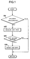
- Fig. 1 shows an example of the case in which the running control of the first motor generator 11 is restricted, and it is judged whether or not the amount of the electric power possible to be charged into the battery 15 from the first motor generator 11 to compensate the output shaft torque at the shifting time, i.e., an acceptance limiting value (or an acceptable electric power) Win is more than the predetermined value, i.e., an acceptance limiting guard value WinG (at Step S21).
- Step S21 In case the answer of Step S21 is YES, specifically, if the battery 15 can sufficiently accept the electric power generated by outputting the negative torque from the first motor generator 11, the normal running control at the shifting time is possible and the routine is therefore returned without any especial control.
- the answer of Step S21 is NO, on the contrary, the battery 15 cannot sufficiently accept the electric power generated by the first motor generator 11, and the first motor generator 11 cannot output the necessary negative torque to compensate the output shaft torque. Therefore, the shift point to decide the gear shift to be executed by the transmission 6 is changed (at Step S22). Specifically, the shift point is calculated. This calculation or change of the shift point is executed for individual acceptance limiting value Win.
- Fig. 2 is a shifting diagram taking the vehicle speed V as its abscissa, and the load Acc represented by the opening of an accelerator etc. as its ordinate.
- a downshift line joining downshift points from the high gear stage H to the low gear stage L, and an upshift line joining upshift points from the low gear stage L to the high gear stage H are provided therein, and both of those shifting lines are to be changed.
- This change of shift point can be made by preparing a formula in which the load and the vehicle speed are used as variables, and by setting the shift point determined on the basis of the formula.
- this change of shift point can be made by preparing map values on behalf of the formula, and by setting the shift point with using the map values.
- Step S23 the gear shift in the transmission 6 is decided on the basis of the load and the vehicle speed at that time, and the changed shift point (Step S23).
- the decision of the gear shift is not satisfied, the answer of Step S23 is NO, and the routine is returned without any especial control.
- the answer of Step S23 is YES because of satisfaction of the decision of the gear shift, on the contrary, an instruction of gear shift is outputted (at Step S24).
- the decision of the gear shift is satisfied in case the running state which is determined on the basis of the vehicle speed V and the load Acc intersect either of the aforementioned upshift line or the downshift line.
- this shifting operation is executed by releasing any of the first brake B1 and the second brake B2 whereas engaging the other brake.
- the torque to be outputted from the main prime mover 1 to the output shaft 2 is temporarily raised by controlling the first motor generator 1, in order to suppress or avoid the fall of the output shaft torque during the shifting operation.
- the acceptance limiting value Win is smaller than the guard value WinG so that the running control of the first motor generator 11 is restricted. As a result, the torque to compensate the fall of the output shaft torque becomes small or zero.
- the shift point is changed to the low load side and the shifting operation is being executed in the low load state so that the fall of the output shaft torque as might otherwise accompany the gear shift is small, and the fall of the output shaft torque can be avoided or reduced by the small compensating torque. Therefore, the fall or fluctuation of the output shaft torque becomes small in case the shifting operation is executed in the transmission 6 by outputting the instruction of the gear shift at Step S24, and the shocks are thereby avoided or suppressed.
- the torque acting on the individual brakes B1 and B2, or the energy amount to be absorbed by those brakes B1 and B2 fall relatively. Therefore, the duration of those breaks B1 and B2 is improved.
- the aforementioned example is constructed such that the shift point is changed continuously, or changed in the plural patterns by the map values.
- the construction may be modified to select the shift points for the normal situation, or for the running control limiting time.
- the example is shown in Fig. 3.
- the shift point for the running control limiting time is selected (at Step S22-1).
- the shift point for the normal situation is selected (at Step S22-2).
- the shift point for the normal situation is the shift point indicated by the solid line in Fig. 2.
- the shift point for running control limiting time is the shift point indicated by the broken line in Fig. 2. and it is changed relatively to the low load side in comparison with the shift point for the normal situation.
- the change of the shift point according to the present invention is, in short, sufficient if the timing of the gear shift is changed. Therefore, the construction may be modified such that the gear shift is decided on the basis of the value which is determined by applying the predetermined correction to the detected parameters such as the load and the vehicle speed as a factor of decision of the gear shift, without changing the shift point to be set on the shifting diagram.
- the second motor generator 5 in case the gear stage is shifted from the low gear stage L to the high gear stage H in the transmission 6, the second motor generator 5 is so power-controlled that the fall of the output shaft torque may be suppressed during the shifting operation. In this case, it is necessary to output the electric power from the battery 29 to the second motor generator 5. However, in case the charging amount SOC of the battery 29 drops, or in case the electric power cannot be outputted sufficiently due to the low temperature, the second motor generator 5 cannot be sufficiently power-controlled. In the control device according to this invention, therefore, the shift point is relatively changed to the low load side in case the power control is restricted in accordance with the condition of the battery 29.
- the shift point is changed by determining the upshift point and the downshift point on the basis of the predetermined calculation or the map values, alternatively, by selecting the shift point for the running control limiting time set in advance.
- the predetermined electric power output limiting value WoutG and the electric power output limiting value Wout at that point of time are to be compared.
- the electric power output limiting value Wout is greater than the guard value WoutG, it is possible to output the electric power sufficiently so that the normal shift point is employed.
- Fig. 4 is a simplified flowchart showing an example of that control. First of all, it is judged whether or not a vehicle speed V is lower than an upper limit vehicle speed VLG of a low gear stage (L mode) L (at Step S31).
- the upper limit vehicle speed VLG is the predetermined vehicle speed to avoid an overrun etc. of the engine 10 or individual motor generators 11 and 5.
- Step S31 it is judged whether or not the aforementioned acceptance limiting value Win is greater than its guard value WinG, or it is judged whether or not the output limiting value Wout is greater than its guard value WinG (at Step S32).
- the answer of Step S32 is NO. In this case, any of the high gear stage H and the low gear stage L is selected (at Step S33).
- This selection of the gear stage at Step S33 is executed on the basis of the running state of the vehicle having the aforementioned hybrid drive unit at that point of time. For example, the low gear stage L is selected in case the vehicle speed is low and a high torque is needed. In case the high torque is not needed but it is necessary to raise an oil temperature immediately etc., on the contrary, the high gear stage H is selected.
- This selection of the gear stage may be operated manually by a driver, or may be executed automatically by the control device.
- This selected gear stage is fixed (at Step S34). Specifically, the gear stage at the start is kept even if the change in the running state such as the load and the vehicle speed occurs. As a result, the gear shift is not caused in the transmission 6 in the state where there is no compensation for the output shaft torque and torque correction by the second motor generator 5. Therefore, the shocks do not deteriorate.
- Step S35 a normal shift control is executed (at Step S35).
- This normal shift control executes the gear shift by deciding the gear shift on the basis of the predetermined shift point, in the state where the running control on the aforementioned individual motor generators 11 and 5 is not restricted. Therefore, the normal shift control is also executed in case the answer of the aforementioned Step S32 is YES, specifically, in case both of the acceptance limiting value Win and the output limiting value Wout are greater than respective guard values WinG and WoutG.
- the control to fix the gear stage may be executed to promote a warm up of the hybrid drive unit.
- An example is shown in a flowchart in Fig. 5.
- a temperature e.g., an oil temperature
- THoG predetermined reference value
- Step S41 it is judged whether or not a temperature (e.g., an oil temperature) THo of the hybrid drive unit is lower than the predetermined reference value THoG.
- Step S41 it is judged whether or not a temperature (e.g., an oil temperature) THo of the hybrid drive unit is lower than the predetermined reference value THoG.
- Step S41 YES
- a motive power loss is large or a controllability of the oil pressure is lowered, because the temperature of the hybrid drive unit is low and a viscosity of the oil is high.
- the transmission 6 is set and fixed to a warm up promotion mode (gear stage) (at Step S42).
- This warm up promotion mode is identical to the gear stage selected at the aforementioned Step S33 shown in Fig. 4, and is the high gear stage H or the low gear stage L selected on the basis of the running condition at that point of time.
- the normal shift control is executed (at Step S43).
- Step S51 it is judged whether or not the aforementioned acceptance limiting value Win is higher than its guard value WinG, or the output limiting value Wout is higher than its guard value WoutG (at Step S51).
- the answer of Step S51 is NO.
- the shift point to decide the gear shift in the transmission 6 is relatively changed to the low speed side in comparison with the shift point in which the gear shift is decided in the normal situation (at Step S52).
- the example is schematically shown in a shifting diagram in Fig. 7.
- This change in the shift point is executed for each of the acceptance limiting value Win and output limiting value Wout. Moreover, a new shift point is determined on the basis of the formula or the map set in advance. Alternatively, the change in the shift point is executed by selecting the shift point for the running control limiting time set in advance. Specifically, the procedure to change the shift point is identical to the aforementioned case in which the shift point is changed to the low load side.
- Step S53 the gear shift in the transmission 6 is judged on the basis of the load and the vehicle speed at that point of time, and the changed shift point (at Step S53).
- the answer of Step S53 is NO, and the routine is returned in this case without any especial control.
- the instruction of gear shift is outputted (at Step S54).
- the shift point for the normal situation is set (at Step S55).
- the shifting operation is executed by releasing any of the first brake B1 and the second brake B2 whereas engaging the other brake.
- the torque to be outputted from the main prime mover 1 to the output shaft 2 is temporarily raised by controlling the first motor generator 11, in order to suppress or avoid the fall of the output shaft torque during the shifting operation.
- the output torque of the second motor generator 5 is raised.
- Step S51 As the answer of Step S51 is YES, the acceptance limiting value Win or the output limiting value Wout is smaller than their guard values WinG and WoutG, and the running controls of any of the motor generators 11 and 5 is restricted. As a result, the torque to compensate the fall of the output shaft torque, or the torque correction of the second motor generator 5 becomes small or zero.
- a time chart in case of shifting from the low gear stage L to the high gear stage H is shown schematically in Fig. 8.
- a substantial shifting operation is started at a point of time t1, and the output shaft torque or the torque acting on the transmission 6 to the output shaft 2 is lowered.
- the torque phase continues to the time point t2, and the inertia phase starts at the time point t2. Therefore, the speed of the second motor generator 5 starts decreasing and the accompanying inertia torque appears on the output shaft 2 thereby to increase the output shaft torque gradually.
- the apply pressure (oil pressure) of the first brake B1 to set the high gear stage H also increases.
- the difference in the speed between before and after the gear shift is small without especially increasing the rising gradient of the apply pressure, and the shifting time is therefore short.
- the rising gradient of the apply pressure is not especially increased, an overshoot of the output shaft torque at the shift ending point of time is small. In this respect, too, the shock as might otherwise accompany the gear shift can be suppressed or prevented.
- the hybrid drive unit constructed as shown in Fig. 11 comprises the second motor generator 5 connected through the transmission 6 to the output shaft 2, so that the torque outputted from the second motor generator 5 can be transmitted to the output shaft 2 with being amplified by the transmission 6. Therefore, it is possible for the vehicle to run with using only the second motor generator 5 as a prime mover.
- This kind of running mode is the EV running (electric vehicle running) mode. In this case, the transmission torque between the second motor generator 5 and the output shaft 2 falls when the gear shift is executed in the transmission 6. Moreover, the output shaft torque cannot be compensated by the torque from the main prime mover 1 side, if the engine 10 is not driven. Therefore, the shifting operation in the EV running mode is controlled as will be described hereinafter.
- Fig. 9 is a flowchart for explaining an example of that control.
- Step S61 it is judged whether or not the oil temperature in the hybrid drive unit is higher than the predetermined value set in advance. This judgment is to judge whether or not the warm up of the hybrid drive unit is completed and possible to execute the gear shift in the transmission 6 as envisioned. Therefore, if the answer of Step S61 is YES, it is judged whether or not the vehicle is in the EV running (at Step S62).
- Step S62 in the EV running'' means the state where the vehicle is run by the motive energy outputted from the second motor generator 5, whereas the engine 10 is not under a starting control and a halting control.
- Step S63 the shifting operation is inhibited (at Step S64). Specifically, a gear shift inhibiting flag is turned ON.
- EV running is the running mode in which the vehicle is run by the motive energy of the second motor generator 5. Therefore, when the gear shift is made in the transmission 6 which connects the second motor generator 5 and the output shaft 2, the torque cannot be transmitted from the second motor generator 5 to the output shaft 2 so that the variation in the output shaft torque, i.e., the shift shock is increased. Therefore, the shifting operation is inhibited in order to avoid this kind of situation. Specifically, the factor of the shocks itself will not be generated.
- Step S65 it is judged whether or not an absolute value of drive demand is smaller than the predetermined demand set in advance. Specifically, it is judged whether or not an acceleration demand or a regenerative braking force at the coasting state is smaller than the predetermined value. In case the answer of Step S65 is NO, the second motor generator 5 is demanded to output the larger torque, or to generate the bigger regenerative braking force. In this case, therefore, a connection state of the second motor generator 5 and the output shaft 2 is kept so as to have the second motor generator 5 perform demanded driving and braking function even if the vehicle speed is low. Specifically, the shifting operation is prohibited (at Step S64).
- Step S65 in case the answer of Step S65 is YES, in other words, in case the vehicle speed is low and the positive or negative drive demand is smaller than the predetermined value, the shifting operation is allowed (at Step S66). Specifically, the gear shift inhibiting flag is turned OFF. It is because the variation in the output shaft torque as might otherwise accompany the gear shift in the transmission 6 and the accompanying shocks are small.
- Step S67 it is judged whether or not the shifting control in the transmission 6 is substantially executed.
- step S67 it is judged whether or not the shifting control in the transmission 6 is substantially executed.
- step S68 the halting of the engine 10 is inhibited.
- the engine 10 is kept in the driving state so as to avoid the fluctuation of the output shaft torque at the shifting time. Therefore, in case the answer of step S67 is NO because of no shifting control, the halting of the engine 10 is allowed (at Step S69).
- step S61 in case the answer of step S61 is NO because of the low oil temperature, the routine is advanced to Step S64 and the shifting operation is inhibited.
- step S62 In case the answer of step S62 is NO because the vehicle is not in the EV running, the normal control is executed. Specifically, it is judged whether or not the engine 10 is under the starting control first of all (Step S70). In case the answer of step S70 is NO, it is judged whether or not an abrupt shifting is occurred in the planetary gear mechanism 12 which synthesizes or distributes the motive energy between the engine 10 and the first motor generator 11 (at Step S71). This can be judged by, for example, whether or not the variation ⁇ Ne in the speed of the engine 10 exceeds the predetermined value.
- step S71 In case the answer of step S71 is NO because of the mild change in the speed, the routine advances to the aforementioned Step S66 and the shifting operation is allowed. In case the answer of step S71 is YES, because of the rapid change in the speed, or because the engine 10 is under the starting control, on the contrary, it is judged whether or not the decision of the gear shift is satisfied, specifically, an existence of the decision of the gear shift is judged (at Step S72).
- step S72 In case the answer of step S72 is YES because the decision of the gear shift is already made, the decision of the gear shift is canceled and the shifting operation is ceased (at Step S73). After this, the shifting operation is inhibited (at Step S74). In case the answer of step S72 is NO because of no decision of the gear shift, moreover, the routine instantly advances to Step S74 and the shifting operation is inhibited.
- the device for executing aforementioned Steps S21, S31 and S51 corresponds to a running restriction judging means or judger of this invention
- device for executing Steps S22, S22-1 and S52 corresponds to a shift point changing means or changer of this invention
- the batteries 15 and 29 shown in Fig. 11 corresponds to an energy accumulator of this invention
- the first motor generator 11 corresponds to a regenerating mechanism of this invention
- the device for executing Step S8 shown in Fig. 13 corresponds to an output torque correcting means or corrector and a shifting time torque correcting means or corrector of this invention.
- the second motor generator 5 corresponds to a drive mechanism of this invention
- the device for executing Step S9 shown in Fig. 13 corresponds to a drive controlling means or controller of this invention
- the device for executing Step S34 corresponds to a gear ratio fixing means or device of this invention
- the device for executing Step S64 corresponds to a gear shift regulating means or regulator of this invention.
- the hybrid drive unit, to which this invention is applied is properly exemplified by the so-called “mechanical distribution type hybrid drive unit", in which the torque of the internal combustion engine and the torque of the first motor generator (or the electric motor) are transmitted to the output member through a synthesis distribution mechanism composed mainly of the planetary gear mechanism, as shown in Fig. 11, and in which the torque of the second motor generator (or the electric motor) is transmitted to that output member through the transmission.
- the hybrid drive unit of the invention may have another construction. In short, a required condition is that the second prime mover is connected through the transmission to the output member.
- the energy accumulator of the invention in short, it is sufficient to charge a running inertial energy of the vehicle. Accordingly, a capacitor, a flywheel and so on, which can charge the energy regardless of the form of the energy, may be used other than the battery. Therefore, the regenerating mechanism is not limited to the motor generator. And the transmission of the invention may be a multiple-stage type transmission or a continuously variable transmission, other than the transmission having the construction to shift the gear stage high and low.
- the shift point is changed in case the energy accumulator cannot output the energy sufficiently or cannot accept the energy, so that the shocks are lightened or prevented.
- the gear shift is executed in the relatively low load state. Therefore, the change in the torque as might otherwise accompany the gear shift becomes so small that the fluctuation of the torque itself is small. Accordingly, the change in the output torque can be suppressed so as not to cause shocks even if the regenerative torque is small.
- the gear shift is executed in the relatively low load state, even when the change in the regenerative torque is small because of the restriction on the regenerative control by the regenerating mechanism of the first prime mover. Therefore, it is possible to suppress or prevent the shocks.
- the gear shift of the case in which any of the prime mover cannot be sufficiently controlled to suppress the change in the output torque at the shifting time is caused relatively in the low speed state.
- the time period necessary for the gear shift is shorten so that the torque change due to the gear shift under the state where any of the prime movers cannot be sufficiently controlled, is ended in a short period of time. Therefore, the shocks as might otherwise accompany the gear shift becomes hard to be felt or light.
- the gear shift is executed by the frictional engagement device, the amount of energy to be absorbed by the frictional member becomes small. Therefore, it is possible to improve the durability of the frictional engagement device.
- the shift point to decide the gear shift in the transmission is changed relatively to the low load side. Therefore, the change in the output torque as might otherwise accompany the gear shift in the transmission becomes small so that the shocks are hard to occur. Moreover, the change in the output torque is also suppressed by the restricted running control of any of the prime movers. Therefore, shocks are prevented or relaxed also in this respect.
- the gear shift is caused in the low load state so that the change in the output torque can be suppressed even if the torque is a small corrected torque of the second prime mover.
- the shocks are prevented or relaxed.
- the gear ratio at the starting time of the vehicle is kept so as not to cause the gear shift in the transmission. Therefore, the gear shift is not caused in the state where the correction of the torque by any of the prime movers cannot be sufficiently executed, so that it is possible to prevent the shocks from deterioration.
- the gear shift in the transmission is regulated, in the state where the vehicle is run by the second prime mover connected through the transmission to the output member. Therefore, the gear shift and the accompanying fluctuation of the torque is not caused, or the fluctuation is regulated, under the state where the output torque cannot be so-called "compensated" by the first prime mover, so that the shocks are suppressed or prevented.
- the output torque of the first prime mover is corrected to the rising side at the shifting time in the transmission, in the state where the torque can be outputted from the first prime mover in which the output member is connected; and the torque can be raised. Therefore, the torque of the output member during the shifting operation in the transmission is compensated by the torque of the first prime mover, and the fall of the output torque at the shifting time or the shock as might otherwise result from the fall of the output torque can be prevented or suppressed.
- a control device of a hybrid drive unit wherein an output member is connected to a first prime mover, and wherein a second prime mover capable of outputting at least one of a positive torque and a negative torque is connected through a transmission to said output member, comprising: a running restriction judging means for judging that a running control of at least one of said first prime mover and said second prime mover is restricted, and a shift point changing means for changing a shift point, in which a decision of a gear shift of said transmission is to be satisfied when the running restriction judging means judges that the running control is restricted, different from the shift point of a case in which the running control is not restricted.
Applications Claiming Priority (2)
| Application Number | Priority Date | Filing Date | Title |
|---|---|---|---|
| JP2002374971A JP3852402B2 (ja) | 2002-12-25 | 2002-12-25 | ハイブリッド駆動装置の制御装置 |
| JP2002374971 | 2002-12-25 |
Publications (2)
| Publication Number | Publication Date |
|---|---|
| EP1433642A1 true EP1433642A1 (fr) | 2004-06-30 |
| EP1433642B1 EP1433642B1 (fr) | 2008-02-20 |
Family
ID=32463553
Family Applications (1)
| Application Number | Title | Priority Date | Filing Date |
|---|---|---|---|
| EP03029735A Expired - Lifetime EP1433642B1 (fr) | 2002-12-25 | 2003-12-23 | Dispositif de commande pour un groupe motopropulseur hybride et méthode de commande associée |
Country Status (6)
| Country | Link |
|---|---|
| US (1) | US7090612B2 (fr) |
| EP (1) | EP1433642B1 (fr) |
| JP (1) | JP3852402B2 (fr) |
| KR (1) | KR100629660B1 (fr) |
| CN (1) | CN100443325C (fr) |
| DE (1) | DE60319200T2 (fr) |
Cited By (3)
| Publication number | Priority date | Publication date | Assignee | Title |
|---|---|---|---|---|
| DE102005030603B4 (de) * | 2004-07-01 | 2014-07-10 | Toyota Jidosha Kabushiki Kaisha | Steuervorrichtung für ein Fahrzeugantriebssystem |
| CN104870868A (zh) * | 2012-12-26 | 2015-08-26 | 日产自动车株式会社 | 电动车辆的变速控制装置 |
| CN110770059A (zh) * | 2017-06-09 | 2020-02-07 | 雷诺股份公司 | 用于生成车辆的动力传动系的电动机器的扭矩设定点的方法及车辆的动力传动系 |
Families Citing this family (41)
| Publication number | Priority date | Publication date | Assignee | Title |
|---|---|---|---|---|
| CN101844510B (zh) * | 2002-12-25 | 2012-06-13 | 丰田自动车株式会社 | 混合驱动单元的控制装置 |
| JP3898654B2 (ja) * | 2003-02-27 | 2007-03-28 | ジヤトコ株式会社 | エンジンのトルク制御装置 |
| JP3807386B2 (ja) * | 2003-06-05 | 2006-08-09 | トヨタ自動車株式会社 | ハイブリッド車の制御装置 |
| JP3758650B2 (ja) * | 2003-06-16 | 2006-03-22 | トヨタ自動車株式会社 | ハイブリッド駆動装置の制御装置 |
| JP3963868B2 (ja) * | 2003-06-23 | 2007-08-22 | トヨタ自動車株式会社 | ハイブリッド駆動装置の制御装置 |
| JP4111140B2 (ja) * | 2004-01-21 | 2008-07-02 | アイシン・エィ・ダブリュ株式会社 | 電動車両駆動制御装置及び電動車両駆動制御方法 |
| JP3982512B2 (ja) * | 2004-03-24 | 2007-09-26 | トヨタ自動車株式会社 | ハイブリッド駆動装置の制御装置及びハイブリッド駆動装置の制御方法 |
| JP4220961B2 (ja) | 2004-12-28 | 2009-02-04 | トヨタ自動車株式会社 | 動力出力装置およびこれを搭載する自動車並びに動力出力装置の制御装置、動力出力装置の制御方法 |
| US7832297B2 (en) | 2005-04-19 | 2010-11-16 | Hewatt Chris B | Method and apparatus for gyroscopic propulsion |
| JP4321530B2 (ja) | 2006-01-27 | 2009-08-26 | トヨタ自動車株式会社 | 車両およびその制御方法 |
| DE102006034932A1 (de) * | 2006-07-28 | 2008-01-31 | Dr.Ing.H.C. F. Porsche Ag | Verfahren und Vorrichtung zur Steuerung eines Hybrid-Fahrzeugantriebs |
| JP5305576B2 (ja) * | 2006-10-16 | 2013-10-02 | 日産自動車株式会社 | 車両の制御装置 |
| US7967091B2 (en) * | 2006-11-16 | 2011-06-28 | Ford Global Technologies, Llc | Hybrid electric vehicle powertrain with engine start and transmission shift arbitration |
| JP2008155802A (ja) * | 2006-12-25 | 2008-07-10 | Toyota Motor Corp | 車両用駆動装置の制御装置 |
| JP4100445B1 (ja) | 2007-01-10 | 2008-06-11 | トヨタ自動車株式会社 | ハイブリッド駆動装置、それを備える車両およびその制御方法 |
| JP4179380B2 (ja) | 2007-01-10 | 2008-11-12 | トヨタ自動車株式会社 | 車両用動力伝達装置の制御装置 |
| JP2008207690A (ja) * | 2007-02-27 | 2008-09-11 | Toyota Motor Corp | 車両用駆動装置の制御装置 |
| JP4760756B2 (ja) * | 2007-03-30 | 2011-08-31 | 日産自動車株式会社 | 車両用回生制動装置 |
| JP2009041601A (ja) * | 2007-08-07 | 2009-02-26 | Hitachi Ltd | 自動変速機の制御装置および制御方法 |
| DE102007038585A1 (de) * | 2007-08-16 | 2009-03-19 | Zf Friedrichshafen Ag | Verfahren zur Lastpunktverschiebung im Hybridbetrieb bei einem parallelen Hybridfahrzeug |
| JP4238927B1 (ja) * | 2007-09-07 | 2009-03-18 | トヨタ自動車株式会社 | 車両用自動変速機の制御装置 |
| US7766109B2 (en) * | 2007-09-28 | 2010-08-03 | Gm Global Technology Operations, Inc. | Hybrid powertrains and methods of operating |
| JP4992684B2 (ja) * | 2007-11-28 | 2012-08-08 | トヨタ自動車株式会社 | ハイブリッド車の制御装置 |
| JP5181739B2 (ja) * | 2008-03-07 | 2013-04-10 | トヨタ自動車株式会社 | 車両用動力伝達装置の制御装置 |
| JP2010036866A (ja) * | 2008-08-08 | 2010-02-18 | Toyota Motor Corp | 車両用動力伝達装置の制御装置 |
| JP2010042708A (ja) * | 2008-08-08 | 2010-02-25 | Toyota Motor Corp | 車両用自動変速機の制御装置 |
| JP5307588B2 (ja) | 2009-03-11 | 2013-10-02 | アイシン・エーアイ株式会社 | 車両の動力伝達制御装置 |
| DE112009004807B4 (de) * | 2009-05-26 | 2016-02-04 | Toyota Jidosha Kabushiki Kaisha | Schaltsteuerungsgerät für ein fahrzeugleistungsübertragungssystem |
| CN102612447B (zh) * | 2010-08-31 | 2014-08-13 | 丰田自动车株式会社 | 车辆的控制装置 |
| US9242545B2 (en) * | 2010-10-20 | 2016-01-26 | GM Global Technology Operations LLC | Negative-torque downshift execution for fixed-gear transmissions |
| KR101251512B1 (ko) * | 2010-12-06 | 2013-04-05 | 기아자동차주식회사 | 하이브리드 차량의 변속 제어방법 |
| JP5750395B2 (ja) * | 2012-03-30 | 2015-07-22 | 本田技研工業株式会社 | 車両用駆動装置 |
| JP2013100095A (ja) * | 2012-12-19 | 2013-05-23 | Nissan Motor Co Ltd | 車両の制御装置 |
| JP5454665B2 (ja) * | 2012-12-19 | 2014-03-26 | 日産自動車株式会社 | ハイブリッド車両の制御装置 |
| TWI523772B (zh) * | 2013-08-23 | 2016-03-01 | 國立屏東科技大學 | 雙動力源電動車之動力分配方法 |
| CN103968006A (zh) * | 2014-04-23 | 2014-08-06 | 佛山科学技术学院 | 一种内联系传动链 |
| KR101592771B1 (ko) | 2014-10-17 | 2016-02-12 | 현대자동차주식회사 | 하이브리드 차량의 변속 제어 방법 |
| DE102015207508A1 (de) * | 2015-04-23 | 2016-10-27 | Zf Friedrichshafen Ag | Planetengetriebevorrichtung mit mehreren Planetenradsatzwellen und wenigstens einer weiteren drehbar gelagerten Welle |
| DE102015207653A1 (de) * | 2015-04-27 | 2016-10-27 | Bayerische Motoren Werke Aktiengesellschaft | Betriebsverfahren für ein an einem zweiachsigen zweispurigen Hybrid-Kraftfahrzeug vorgesehenen System zur Veränderung des Eigenlenkverhaltens |
| EP3517346A4 (fr) * | 2016-09-21 | 2020-05-06 | NSK Ltd. | Dispositif d'entraînement de véhicule électrique |
| CN113978447B (zh) * | 2021-10-27 | 2024-01-09 | 岚图汽车科技有限公司 | 一种扭矩控制方法及相关设备 |
Citations (5)
| Publication number | Priority date | Publication date | Assignee | Title |
|---|---|---|---|---|
| US5088354A (en) * | 1989-11-30 | 1992-02-18 | Toyota Jidosha Kabushiki Kaisha | Shift control system and method for automatic transmissions |
| US5257189A (en) * | 1990-08-07 | 1993-10-26 | Toyota Jidosha Kabushiki Kaisha | Speed stage shifting of automatic transmission of automobile in relation to yaw rate in steering |
| EP0641684A1 (fr) * | 1993-09-07 | 1995-03-08 | Honda Giken Kogyo Kabushiki Kaisha | Dispositif de commande de propulsion d'un véhicule |
| US5847469A (en) * | 1996-02-29 | 1998-12-08 | Toyota Jidosha Kabushiki Kaisha | Hybrid drive system wherein electric motor or engine is selectively used for rearward driving of vehicle |
| WO2002006072A1 (fr) * | 2000-07-18 | 2002-01-24 | Siemens Aktiengesellschaft | Unite de commande pour transmission et procede permettant sa mise en fonctionnement |
Family Cites Families (28)
| Publication number | Priority date | Publication date | Assignee | Title |
|---|---|---|---|---|
| US192494A (en) * | 1877-06-26 | Improvement in fence-wire tighteners | ||
| US3623568A (en) | 1968-05-31 | 1971-11-30 | Nissan Motor | Electromechanical power train system for an automotive vehicle |
| JP3227905B2 (ja) | 1993-04-30 | 2001-11-12 | 株式会社エクォス・リサーチ | 電気モータ駆動車輌 |
| JPH099414A (ja) | 1995-06-14 | 1997-01-10 | Aqueous Res:Kk | ハイブリッド車両 |
| JP3518163B2 (ja) | 1996-05-10 | 2004-04-12 | トヨタ自動車株式会社 | 車両の制御装置 |
| US5887670A (en) | 1996-05-16 | 1999-03-30 | Toyota Jidosha Kabushiki Kaisha | Vehicle power transmitting system having devices for electrically and mechanically disconnecting power source and vehicle drive wheel upon selection of neutral state |
| JP3541571B2 (ja) | 1996-07-05 | 2004-07-14 | トヨタ自動車株式会社 | ハイブリッド車両の制御装置 |
| JP3520668B2 (ja) | 1996-06-11 | 2004-04-19 | トヨタ自動車株式会社 | ハイブリッド車両の制御装置 |
| JP3539075B2 (ja) | 1996-06-14 | 2004-06-14 | トヨタ自動車株式会社 | ハイブリッド車両の駆動制御装置 |
| GB9700960D0 (en) | 1997-01-17 | 1997-03-05 | Rover Group | Hybrid vehicle powertrain control |
| DE19849156A1 (de) | 1998-03-27 | 1999-09-30 | Bosch Gmbh Robert | Antriebsstrang für ein Kraftfahrzeug |
| JP2000220731A (ja) | 1999-02-04 | 2000-08-08 | Mitsubishi Motors Corp | 電動車両 |
| JP3515006B2 (ja) | 1999-02-23 | 2004-04-05 | 本田技研工業株式会社 | ハイブリッド車両の制御装置 |
| JP2000295720A (ja) | 1999-04-02 | 2000-10-20 | Mitsubishi Motors Corp | 電気自動車の制御装置 |
| JP2000295709A (ja) | 1999-04-06 | 2000-10-20 | Toyota Motor Corp | 電気自動車の変速時制御装置 |
| JP3817982B2 (ja) | 1999-08-06 | 2006-09-06 | トヨタ自動車株式会社 | ハイブリッド車 |
| JP2001146121A (ja) | 1999-11-19 | 2001-05-29 | Toyota Motor Corp | 変速機付きハイブリッド車両の制御装置 |
| JP2001153218A (ja) | 1999-11-26 | 2001-06-08 | Toyota Motor Corp | 車両の制御装置 |
| JP4714956B2 (ja) | 1999-12-15 | 2011-07-06 | トヨタ自動車株式会社 | 車両の制御装置 |
| JP3454226B2 (ja) | 2000-05-11 | 2003-10-06 | トヨタ自動車株式会社 | ハイブリッド車両の制御装置 |
| US6371878B1 (en) | 2000-08-22 | 2002-04-16 | New Venture Gear, Inc. | Electric continuously variable transmission |
| JP3573202B2 (ja) | 2000-11-06 | 2004-10-06 | 三菱自動車工業株式会社 | ハイブリッド車両のトルク制御装置 |
| DE10058020B4 (de) | 2000-11-23 | 2013-09-12 | Burani Consulting Limited Liability Company | Kraftfahrzeugantrieb |
| JP3893960B2 (ja) | 2001-01-12 | 2007-03-14 | トヨタ自動車株式会社 | 動力伝達装置 |
| JP3580257B2 (ja) | 2001-02-05 | 2004-10-20 | トヨタ自動車株式会社 | ハイブリッド車 |
| JP3638876B2 (ja) | 2001-03-01 | 2005-04-13 | 株式会社日立製作所 | 車両の駆動装置及び車両 |
| US6478705B1 (en) * | 2001-07-19 | 2002-11-12 | General Motors Corporation | Hybrid electric powertrain including a two-mode electrically variable transmission |
| JP2003130199A (ja) | 2001-10-24 | 2003-05-08 | Nissan Motor Co Ltd | 有段変速機を備えたハイブリッド車両 |
-
2002
- 2002-12-25 JP JP2002374971A patent/JP3852402B2/ja not_active Expired - Fee Related
-
2003
- 2003-11-27 KR KR1020030085192A patent/KR100629660B1/ko not_active IP Right Cessation
- 2003-12-19 US US10/739,286 patent/US7090612B2/en not_active Expired - Fee Related
- 2003-12-23 DE DE60319200T patent/DE60319200T2/de not_active Expired - Lifetime
- 2003-12-23 EP EP03029735A patent/EP1433642B1/fr not_active Expired - Lifetime
- 2003-12-25 CN CNB2003101130220A patent/CN100443325C/zh not_active Expired - Fee Related
Patent Citations (5)
| Publication number | Priority date | Publication date | Assignee | Title |
|---|---|---|---|---|
| US5088354A (en) * | 1989-11-30 | 1992-02-18 | Toyota Jidosha Kabushiki Kaisha | Shift control system and method for automatic transmissions |
| US5257189A (en) * | 1990-08-07 | 1993-10-26 | Toyota Jidosha Kabushiki Kaisha | Speed stage shifting of automatic transmission of automobile in relation to yaw rate in steering |
| EP0641684A1 (fr) * | 1993-09-07 | 1995-03-08 | Honda Giken Kogyo Kabushiki Kaisha | Dispositif de commande de propulsion d'un véhicule |
| US5847469A (en) * | 1996-02-29 | 1998-12-08 | Toyota Jidosha Kabushiki Kaisha | Hybrid drive system wherein electric motor or engine is selectively used for rearward driving of vehicle |
| WO2002006072A1 (fr) * | 2000-07-18 | 2002-01-24 | Siemens Aktiengesellschaft | Unite de commande pour transmission et procede permettant sa mise en fonctionnement |
Cited By (6)
| Publication number | Priority date | Publication date | Assignee | Title |
|---|---|---|---|---|
| DE102005030603B4 (de) * | 2004-07-01 | 2014-07-10 | Toyota Jidosha Kabushiki Kaisha | Steuervorrichtung für ein Fahrzeugantriebssystem |
| CN104870868A (zh) * | 2012-12-26 | 2015-08-26 | 日产自动车株式会社 | 电动车辆的变速控制装置 |
| EP2940348A4 (fr) * | 2012-12-26 | 2016-03-09 | Nissan Motor | Dispositif de commande de changement de vitesses de véhicule électrique |
| US9662998B2 (en) | 2012-12-26 | 2017-05-30 | Nissan Motor Co., Ltd. | Electric vehicle gear shifting control device |
| CN110770059A (zh) * | 2017-06-09 | 2020-02-07 | 雷诺股份公司 | 用于生成车辆的动力传动系的电动机器的扭矩设定点的方法及车辆的动力传动系 |
| CN110770059B (zh) * | 2017-06-09 | 2023-06-23 | 雷诺股份公司 | 用于生成车辆的动力传动系的电动机器的扭矩设定点的方法及车辆的动力传动系 |
Also Published As
| Publication number | Publication date |
|---|---|
| JP2004204957A (ja) | 2004-07-22 |
| US20040192494A1 (en) | 2004-09-30 |
| EP1433642B1 (fr) | 2008-02-20 |
| KR20040057915A (ko) | 2004-07-02 |
| DE60319200T2 (de) | 2009-04-30 |
| DE60319200D1 (de) | 2008-04-03 |
| US7090612B2 (en) | 2006-08-15 |
| CN100443325C (zh) | 2008-12-17 |
| CN1513690A (zh) | 2004-07-21 |
| JP3852402B2 (ja) | 2006-11-29 |
| KR100629660B1 (ko) | 2006-09-29 |
Similar Documents
| Publication | Publication Date | Title |
|---|---|---|
| EP1433642B1 (fr) | Dispositif de commande pour un groupe motopropulseur hybride et méthode de commande associée | |
| CA2511982C (fr) | Dispositif de commande d'unite d'entrainement hybride | |
| US7434641B2 (en) | Control apparatus of hybrid vehicle | |
| EP3395597B1 (fr) | Unité d'entraînement pour véhicule hybride | |
| US7426973B2 (en) | Hybrid power unit | |
| US7108630B2 (en) | Control system for hybrid drive unit | |
| US7878281B2 (en) | Transmitting state switching control apparatus for hybrid vehicle | |
| US7220212B2 (en) | Control system for hybrid vehicles | |
| US7976428B2 (en) | Control system for drive unit of vehicle | |
| JP4001013B2 (ja) | ハイブリッド駆動装置の制御装置 | |
| JP3852404B2 (ja) | ハイブリッド駆動装置の制御装置 | |
| JP4127049B2 (ja) | ハイブリッド駆動装置の制御装置 | |
| JP4135022B2 (ja) | ハイブリッド駆動装置の制御装置 | |
| JP3852403B2 (ja) | ハイブリッド駆動装置の制御装置 | |
| US7134982B2 (en) | Control system for hybrid drive unit | |
| US10605359B2 (en) | Shift control system for vehicle | |
| JP3651469B2 (ja) | 変速機の制御装置 | |
| JP4070666B2 (ja) | ハイブリッド車の制御装置 | |
| JP4127294B2 (ja) | ハイブリッド駆動装置の制御装置 | |
| JP3891209B2 (ja) | ハイブリッド駆動装置の制御装置 | |
| JP3928600B2 (ja) | ハイブリッド車の制御装置 |
Legal Events
| Date | Code | Title | Description |
|---|---|---|---|
| PUAI | Public reference made under article 153(3) epc to a published international application that has entered the european phase |
Free format text: ORIGINAL CODE: 0009012 |
|
| 17P | Request for examination filed |
Effective date: 20031223 |
|
| AK | Designated contracting states |
Kind code of ref document: A1 Designated state(s): AT BE BG CH CY CZ DE DK EE ES FI FR GB GR HU IE IT LI LU MC NL PT RO SE SI SK TR |
|
| AX | Request for extension of the european patent |
Extension state: AL LT LV MK |
|
| 17Q | First examination report despatched |
Effective date: 20041018 |
|
| AKX | Designation fees paid |
Designated state(s): DE FR GB IT |
|
| GRAP | Despatch of communication of intention to grant a patent |
Free format text: ORIGINAL CODE: EPIDOSNIGR1 |
|
| GRAS | Grant fee paid |
Free format text: ORIGINAL CODE: EPIDOSNIGR3 |
|
| GRAA | (expected) grant |
Free format text: ORIGINAL CODE: 0009210 |
|
| AK | Designated contracting states |
Kind code of ref document: B1 Designated state(s): DE FR GB IT |
|
| REG | Reference to a national code |
Ref country code: GB Ref legal event code: FG4D |
|
| RIC1 | Information provided on ipc code assigned before grant |
Ipc: B60W 10/10 20060101AFI20080115BHEP |
|
| REF | Corresponds to: |
Ref document number: 60319200 Country of ref document: DE Date of ref document: 20080403 Kind code of ref document: P |
|
| ET | Fr: translation filed | ||
| PLBE | No opposition filed within time limit |
Free format text: ORIGINAL CODE: 0009261 |
|
| STAA | Information on the status of an ep patent application or granted ep patent |
Free format text: STATUS: NO OPPOSITION FILED WITHIN TIME LIMIT |
|
| 26N | No opposition filed |
Effective date: 20081121 |
|
| REG | Reference to a national code |
Ref country code: GB Ref legal event code: 746 Effective date: 20120917 |
|
| REG | Reference to a national code |
Ref country code: DE Ref legal event code: R084 Ref document number: 60319200 Country of ref document: DE Effective date: 20120924 |
|
| PGFP | Annual fee paid to national office [announced via postgrant information from national office to epo] |
Ref country code: DE Payment date: 20141216 Year of fee payment: 12 Ref country code: GB Payment date: 20141217 Year of fee payment: 12 |
|
| PGFP | Annual fee paid to national office [announced via postgrant information from national office to epo] |
Ref country code: FR Payment date: 20141208 Year of fee payment: 12 |
|
| PGFP | Annual fee paid to national office [announced via postgrant information from national office to epo] |
Ref country code: IT Payment date: 20141127 Year of fee payment: 12 |
|
| REG | Reference to a national code |
Ref country code: DE Ref legal event code: R119 Ref document number: 60319200 Country of ref document: DE |
|
| GBPC | Gb: european patent ceased through non-payment of renewal fee |
Effective date: 20151223 |
|
| REG | Reference to a national code |
Ref country code: FR Ref legal event code: ST Effective date: 20160831 |
|
| PG25 | Lapsed in a contracting state [announced via postgrant information from national office to epo] |
Ref country code: DE Free format text: LAPSE BECAUSE OF NON-PAYMENT OF DUE FEES Effective date: 20160701 Ref country code: GB Free format text: LAPSE BECAUSE OF NON-PAYMENT OF DUE FEES Effective date: 20151223 |
|
| PG25 | Lapsed in a contracting state [announced via postgrant information from national office to epo] |
Ref country code: FR Free format text: LAPSE BECAUSE OF NON-PAYMENT OF DUE FEES Effective date: 20151231 |
|
| PG25 | Lapsed in a contracting state [announced via postgrant information from national office to epo] |
Ref country code: IT Free format text: LAPSE BECAUSE OF NON-PAYMENT OF DUE FEES Effective date: 20151223 |