EP1426224A1 - Einrichtung zur Rohluftansaugung für eine Brennkraftmaschine - Google Patents
Einrichtung zur Rohluftansaugung für eine Brennkraftmaschine Download PDFInfo
- Publication number
- EP1426224A1 EP1426224A1 EP03024265A EP03024265A EP1426224A1 EP 1426224 A1 EP1426224 A1 EP 1426224A1 EP 03024265 A EP03024265 A EP 03024265A EP 03024265 A EP03024265 A EP 03024265A EP 1426224 A1 EP1426224 A1 EP 1426224A1
- Authority
- EP
- European Patent Office
- Prior art keywords
- air
- air inlet
- inlet openings
- boundary wall
- bow
- Prior art date
- Legal status (The legal status is an assumption and is not a legal conclusion. Google has not performed a legal analysis and makes no representation as to the accuracy of the status listed.)
- Granted
Links
Images

Classifications
-
- B—PERFORMING OPERATIONS; TRANSPORTING
- B60—VEHICLES IN GENERAL
- B60K—ARRANGEMENT OR MOUNTING OF PROPULSION UNITS OR OF TRANSMISSIONS IN VEHICLES; ARRANGEMENT OR MOUNTING OF PLURAL DIVERSE PRIME-MOVERS IN VEHICLES; AUXILIARY DRIVES FOR VEHICLES; INSTRUMENTATION OR DASHBOARDS FOR VEHICLES; ARRANGEMENTS IN CONNECTION WITH COOLING, AIR INTAKE, GAS EXHAUST OR FUEL SUPPLY OF PROPULSION UNITS IN VEHICLES
- B60K13/00—Arrangement in connection with combustion air intake or gas exhaust of propulsion units
- B60K13/02—Arrangement in connection with combustion air intake or gas exhaust of propulsion units concerning intake
Definitions
- the invention relates to a device for raw air intake for a Internal combustion engine according to the preamble of claim 1.
- a device which avoids these disadvantages and a raw air free of enrichments Air filter housing can be fed.
- the main advantages achieved with the invention are that over the encapsulated air storage space a pre-separation for water, snow, dirt and the like. takes place so that only pure untreated air is introduced into an intake port of an air filter housing becomes.
- This is achieved by placing at least one intake port of an air filter housing in an encapsulated air storage space of the device opens, the front of one Bow trim and rear of a subsequent arched Room boundary wall to the engine compartment is completed. In this is in At least one air inlet opening provided with the floor area Air intake ports in the bow of the vehicle communicates.
- the intake manifolds are each elastic at the free end Surround molding, which is close to the arched room boundary wall and a bow trim is arranged.
- an end seal of the Air storage space achieved towards the engine compartment, so that the air supplied completely to the Air filter housing can be fed.
- Air inlet openings immediately adjacent to the air inlet openings in the bow of the Vehicle are Air inlet openings immediately adjacent to the air inlet openings in the bow of the Vehicle arranged. Furthermore, it is provided according to the invention that the curved Room boundary wall with a tangential plane at an acute angle to one horizontal vehicle plane is arranged and that the air inlet openings - in relation on the direction of travel - in the front area of the room boundary wall or in the floor of the Room boundary wall and with a height distance immediately adjacent to Mouth opening of the intake manifold are arranged. This can cause contamination separated and settle in the lower part of the room because the mouth of the Intake port or the intake port higher than the air inlet openings in the Room boundary wall are arranged.
- the outer surface of the curved room boundary wall of the encapsulated air storage space as an air guide surface for Cooling air can be used to a cooler module.
- the air inlet openings can also be provided with a sieve, a flap or the like be so that significant impurities in the supplied air from the start sieved out, separated or held.
- an encapsulated air storage space 2 is arranged, the outside of a bow panel 3, inside of a curved room boundary wall 4 and on two end faces 5, 6 from an elastic molded part 7 to the engine compartment 8 tight is completed.
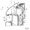
- At least one intake port 9 for raw air opens into the air storage space 2 Air filter housing 10, which is held in the molded part 7 and sealed at the end, as in particular Fig. 2 shows in more detail.
- the space boundary wall 4 is arched towards the engine compartment 8 and a tangent plane Y-Y of the space boundary wall 4 is under an acute one Angle ⁇ made to a horizontal plane X-X of the vehicle.
- air inlet openings 11 are provided in the front area of the room boundary wall. These are at a height distance h and adjacent to the mouth opening 12 of the Intake 9 arranged for raw air.
- air inlet openings 13 provided that an air flow 14 to the air inlet openings 11 of the Guide the room boundary wall 4 into the air storage space 2.
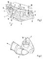
- this room 2 is shown in a diagrammatic representation, with the attitude the bow trim 3 a grid-shaped support member 14 is provided, but which is completely covered by the bow trim 3.
- the air flow 14 entering through the air inlet openings 13 also acts on Radiator module 15, which - in relation to the direction of travel F - behind the air storage space 2 is arranged, wherein the curved space boundary wall 4 serves as an air guiding surface.
- the air inlet openings 11 and 12 can also by means of screens, flaps or the like be covered so that snow, sand, water and other external funds are not or only can partially enter room 2.
- the air 14 flows over the Air inlet openings 13 in the bow 1 of the vehicle and a partial air flow flows to the Radiator module 15 and a further partial air flow flows through the air inlet openings 11 in the air storage space 2, as the arrows show.
- the Air inlet openings 11 arranged mouth openings 12 of the intake manifold 9 separated or separated and thus do not get into the air filter housing.
Landscapes
- Engineering & Computer Science (AREA)
- Chemical & Material Sciences (AREA)
- Combustion & Propulsion (AREA)
- Transportation (AREA)
- Mechanical Engineering (AREA)
- Cooling, Air Intake And Gas Exhaust, And Fuel Tank Arrangements In Propulsion Units (AREA)
- Valve Device For Special Equipments (AREA)
- Electrical Control Of Ignition Timing (AREA)
- Output Control And Ontrol Of Special Type Engine (AREA)
Abstract
Description
- Fig. 1
- eine schaubildliche Darstellung auf einen Stauraum unter Weglassung des Bugverkleidung mit Ansaugstutzen,
- Fig. 2
- eine schaubildliche Darstellung auf einen mit einem elastischen Formteil verbundenen Ansaugstutzen eines Luftfiltergehäuses,
- Fig. 3
- einen Querschnitt durch einen im Bug des Fahrzeugs angeordneten Luftstauraum und
- Fig. 4
- einen weiteren Querschnitt durch den Luftstauraum mit Ansaugstutzen und Kühlermodul.
Claims (6)
- Einrichtung zur Rohluftansaugung für eine Brennkraftmaschine über einen in einem Gehäuse angeordneten Luftfilter, die im Bug eines Fahrzeugs angeordnet ist, und mit bugseitigen Lufteinlaßöffnungen in Verbindung steht, dadurch gekennzeichnet, daß mindestens ein Ansaugstutzen (9) eines Luftfiltergehäuses in einem rundum gekapselten Luftstauraum (2) der Einrichtung einmündet, welcher vorderseitig von einer Bugverkleidung (3) und rückseitig von einer anschließenden gewölbten Raumbegrenzungswand (4) zum Motorraum (8) hin abgeschlossen ist, in der im Bodenbereich der Wand (4) mindestens eine Lufteintrittsöffnung (11) bzw. (12) angeordnet ist, und die mit den Lufteinlaßöffnungen (13) im Fahrzeugbug in Verbindung stehen.
- Einrichtung nach Anspruch 1, dadurch gekennzeichnet, daß der Ansaugstutzen (9) jeweils am freien Ende von einem elastischen Formteil (7) umgeben ist, das dicht anliegend zur gewölbtem Raumbegrenzungswand (4) und zu einer Bugverkleidung (3) angeordnet ist und stirnseitige Abdichtungen des Luftsautraumes (2) bilden.
- Einrichtung nach den Ansprüchen 1 oder 2, dadurch gekennzeichnet, daß die gewölbte Raumbegrenzungswand (4) mit einer Tangentialebene (Y-Y) unter einem spitzen Winkel (α) zu einer horizontalen Fahrzeugebene (X-X) angeordnet ist und die Lufteintrittsöffnungen (11) - in Bezug auf die Fahrtrichtung (F) - im vorderen Bereich der Raumbegrenzungswand (4), mit einem Höhenabstand (h) und unmittelbar benachbart zur Mündungsöffnung (12) des Ansaugstutzens (9) angeordnet sind.
- Einrichtung nach den Ansprüchen 1, 2 oder 3, dadurch gekennzeichnet, daß die Lufteinlaßöffnungen (11) bzw. (12) angrenzend zu den bugseitigen Lufteintrittsöffnungen (13) angeordnet sind.
- Einrichtung nach einem der vorhergehenden Ansprüche, dadurch gekennzeichnet, daß eine Außenfläche der gewölbten Raumbegrenzungswand (4) des gekapselten Luftstauraumes (2) als Luftleitfläche für Kühlluft zu einem Kühlermodul (15) verwendet wird.
- Einrichtung nach einem der vorhergehenden Ansprüche, dadurch gekennzeichnet, daß die Lufteintrittsöffnungen (11) bzw. (12) in der Raumbegrenzungswand (4) mit einem Sieb und/oder einer Schwenkklappe abgedeckt sind.
Applications Claiming Priority (2)
| Application Number | Priority Date | Filing Date | Title |
|---|---|---|---|
| DE10257299A DE10257299B4 (de) | 2002-12-07 | 2002-12-07 | Einrichtung zur Rohluftansaugung für eine Brennkraftmaschine |
| DE10257299 | 2002-12-07 |
Publications (2)
| Publication Number | Publication Date |
|---|---|
| EP1426224A1 true EP1426224A1 (de) | 2004-06-09 |
| EP1426224B1 EP1426224B1 (de) | 2006-07-12 |
Family
ID=32309041
Family Applications (1)
| Application Number | Title | Priority Date | Filing Date |
|---|---|---|---|
| EP03024265A Expired - Lifetime EP1426224B1 (de) | 2002-12-07 | 2003-10-23 | Einrichtung zur Rohluftansaugung für eine Brennkraftmaschine |
Country Status (6)
| Country | Link |
|---|---|
| US (1) | US7059439B2 (de) |
| EP (1) | EP1426224B1 (de) |
| JP (1) | JP4388798B2 (de) |
| AT (1) | ATE332821T1 (de) |
| DE (2) | DE10257299B4 (de) |
| ES (1) | ES2262934T3 (de) |
Cited By (2)
| Publication number | Priority date | Publication date | Assignee | Title |
|---|---|---|---|---|
| US8424937B2 (en) | 2008-04-28 | 2013-04-23 | Renault S.A.S. | Automobile body including a bearing for a bumper-forming member and an air intake duct to the engine |
| WO2017102681A1 (en) * | 2015-12-15 | 2017-06-22 | Jaguar Land Rover Limited | Contaminant separation device |
Families Citing this family (13)
| Publication number | Priority date | Publication date | Assignee | Title |
|---|---|---|---|---|
| KR100589144B1 (ko) * | 2003-10-14 | 2006-06-12 | 현대자동차주식회사 | 차량의 흡기장치 |
| US7234555B2 (en) | 2004-07-12 | 2007-06-26 | Honda Motor Co., Ltd. | Secondary path automobile air intake system |
| US8201651B2 (en) | 2004-07-12 | 2012-06-19 | Honda Motor Co., Ltd. | Automobile over-bulkhead air intake system |
| US7237635B2 (en) | 2004-07-12 | 2007-07-03 | Honda Motor Co., Ltd. | Automobile over-bulkhead air intake system |
| WO2010004889A1 (ja) | 2008-07-08 | 2010-01-14 | トヨタ自動車株式会社 | 車両の吸気構造 |
| US8147578B2 (en) * | 2009-04-15 | 2012-04-03 | Cummins Filtration Ip, Inc. | Reduced restriction air filter |
| US8540043B2 (en) | 2010-08-30 | 2013-09-24 | Honda Motor Co., Ltd. | Over bulkhead air intake for reduced snow ingestion |
| US8528679B2 (en) * | 2010-11-09 | 2013-09-10 | Honda Motor Co., Ltd. | Air separating intake scoop for air intake system |
| US8439143B2 (en) | 2011-02-21 | 2013-05-14 | Honda Motor Co., Ltd. | Over bulkhead air intake system |
| USD710762S1 (en) * | 2013-10-16 | 2014-08-12 | Ford Motor Company | Vehicle exterior |
| TWM566154U (zh) * | 2018-03-15 | 2018-09-01 | 光陽工業股份有限公司 | 引擎無段變速系統冷卻風的集氣箱結構 |
| JP7159722B2 (ja) * | 2018-09-11 | 2022-10-25 | マツダ株式会社 | エンジンの吸気装置 |
| US12703239B2 (en) * | 2023-08-17 | 2026-08-11 | Fca Us Llc | Ram air duct and deflector |
Citations (9)
| Publication number | Priority date | Publication date | Assignee | Title |
|---|---|---|---|---|
| CH337365A (de) * | 1954-04-17 | 1959-03-31 | Kreidler Alfred Dipl Ing | Ansaugeinrichtung für Vergasermotoren, insbesondere für Motorfahrräder |
| JPS54148922A (en) * | 1978-05-13 | 1979-11-21 | Daihatsu Motor Co Ltd | Air intake device for automotive engine |
| GB2110174A (en) * | 1981-10-29 | 1983-06-15 | Nissan Motor | Water-proof structure for air cleaner of automotive internal combustion engine |
| US4533012A (en) * | 1983-04-15 | 1985-08-06 | Toyota Jidosha Kabushiki Kaisha | Intake device of an internal combustion engine |
| JPH07243357A (ja) * | 1994-02-28 | 1995-09-19 | Suzuki Motor Corp | 船舶エンジン用吸気装置 |
| JPH10213033A (ja) * | 1997-01-31 | 1998-08-11 | Suzuki Motor Corp | 内燃機関の吸気構造 |
| JP2001221113A (ja) * | 2000-02-07 | 2001-08-17 | Kawasaki Heavy Ind Ltd | エアクリーナ及びその空気取り入れ口構造 |
| JP2002211252A (ja) * | 2001-01-15 | 2002-07-31 | Nissan Motor Co Ltd | 自動車の吸気ダクト取付部構造 |
| US20030042055A1 (en) * | 2001-08-31 | 2003-03-06 | Honda Giken Kogyo Kabushiki Kaisha | Air-intake structure around front grille for vehicle |
Family Cites Families (8)
| Publication number | Priority date | Publication date | Assignee | Title |
|---|---|---|---|---|
| JPS59294Y2 (ja) * | 1979-09-21 | 1984-01-06 | 本田技研工業株式会社 | 自動二輪車用エアクリ−ナ装置 |
| JPS6239938Y2 (de) * | 1981-01-21 | 1987-10-13 | ||
| JP2526659Y2 (ja) * | 1991-06-24 | 1997-02-19 | マツダ株式会社 | 車両吸気ダクトの吸気取入構造 |
| DE9202785U1 (de) * | 1992-03-03 | 1992-04-23 | Adam Opel AG, 6090 Rüsselsheim | Struktur für die Motorluftansaugung von Brennkraftmaschinen |
| JP3646577B2 (ja) * | 1999-07-29 | 2005-05-11 | トヨタ車体株式会社 | 車両のインタークーラ冷却用ダクト |
| JP2001088790A (ja) * | 1999-09-28 | 2001-04-03 | Yamaha Motor Co Ltd | 小型滑走艇の吸気消音構造 |
| JP3879421B2 (ja) * | 2001-03-22 | 2007-02-14 | スズキ株式会社 | 鞍乗型4輪車 |
| US6695091B2 (en) * | 2001-08-28 | 2004-02-24 | Trw Inc. | Electric steering motor with internal circuit board |
-
2002
- 2002-12-07 DE DE10257299A patent/DE10257299B4/de not_active Expired - Fee Related
-
2003
- 2003-10-23 AT AT03024265T patent/ATE332821T1/de active
- 2003-10-23 ES ES03024265T patent/ES2262934T3/es not_active Expired - Lifetime
- 2003-10-23 EP EP03024265A patent/EP1426224B1/de not_active Expired - Lifetime
- 2003-10-23 DE DE50304204T patent/DE50304204D1/de not_active Expired - Lifetime
- 2003-12-02 JP JP2003403229A patent/JP4388798B2/ja not_active Expired - Fee Related
- 2003-12-03 US US10/725,437 patent/US7059439B2/en not_active Expired - Lifetime
Patent Citations (9)
| Publication number | Priority date | Publication date | Assignee | Title |
|---|---|---|---|---|
| CH337365A (de) * | 1954-04-17 | 1959-03-31 | Kreidler Alfred Dipl Ing | Ansaugeinrichtung für Vergasermotoren, insbesondere für Motorfahrräder |
| JPS54148922A (en) * | 1978-05-13 | 1979-11-21 | Daihatsu Motor Co Ltd | Air intake device for automotive engine |
| GB2110174A (en) * | 1981-10-29 | 1983-06-15 | Nissan Motor | Water-proof structure for air cleaner of automotive internal combustion engine |
| US4533012A (en) * | 1983-04-15 | 1985-08-06 | Toyota Jidosha Kabushiki Kaisha | Intake device of an internal combustion engine |
| JPH07243357A (ja) * | 1994-02-28 | 1995-09-19 | Suzuki Motor Corp | 船舶エンジン用吸気装置 |
| JPH10213033A (ja) * | 1997-01-31 | 1998-08-11 | Suzuki Motor Corp | 内燃機関の吸気構造 |
| JP2001221113A (ja) * | 2000-02-07 | 2001-08-17 | Kawasaki Heavy Ind Ltd | エアクリーナ及びその空気取り入れ口構造 |
| JP2002211252A (ja) * | 2001-01-15 | 2002-07-31 | Nissan Motor Co Ltd | 自動車の吸気ダクト取付部構造 |
| US20030042055A1 (en) * | 2001-08-31 | 2003-03-06 | Honda Giken Kogyo Kabushiki Kaisha | Air-intake structure around front grille for vehicle |
Non-Patent Citations (4)
| Title |
|---|
| PATENT ABSTRACTS OF JAPAN vol. 1996, no. 01 31 January 1996 (1996-01-31) * |
| PATENT ABSTRACTS OF JAPAN vol. 1998, no. 13 30 November 1998 (1998-11-30) * |
| PATENT ABSTRACTS OF JAPAN vol. 2000, no. 25 12 April 2001 (2001-04-12) * |
| PATENT ABSTRACTS OF JAPAN vol. 2002, no. 11 6 November 2002 (2002-11-06) * |
Cited By (3)
| Publication number | Priority date | Publication date | Assignee | Title |
|---|---|---|---|---|
| US8424937B2 (en) | 2008-04-28 | 2013-04-23 | Renault S.A.S. | Automobile body including a bearing for a bumper-forming member and an air intake duct to the engine |
| WO2017102681A1 (en) * | 2015-12-15 | 2017-06-22 | Jaguar Land Rover Limited | Contaminant separation device |
| DE112016005731B4 (de) | 2015-12-15 | 2026-02-26 | Jaguar Land Rover Limited | Vorrichtung zum Abscheiden von Verunreinigungen |
Also Published As
| Publication number | Publication date |
|---|---|
| US20040108152A1 (en) | 2004-06-10 |
| DE50304204D1 (de) | 2006-08-24 |
| DE10257299B4 (de) | 2005-02-03 |
| US7059439B2 (en) | 2006-06-13 |
| DE10257299A1 (de) | 2004-06-24 |
| ATE332821T1 (de) | 2006-08-15 |
| JP2004190671A (ja) | 2004-07-08 |
| EP1426224B1 (de) | 2006-07-12 |
| ES2262934T3 (es) | 2006-12-01 |
| JP4388798B2 (ja) | 2009-12-24 |
Similar Documents
| Publication | Publication Date | Title |
|---|---|---|
| DE10257299B4 (de) | Einrichtung zur Rohluftansaugung für eine Brennkraftmaschine | |
| DE102005012169A1 (de) | Unterhaubenansaugsystem für Motorluft | |
| DE3321804C2 (de) | Vorrichtung zum Abführen von Warmluft aus dem Motorraum von Kraftwagen | |
| DE112017006736T5 (de) | Dichtungsanordnung für die motorhaube eines kraftfahrzeugs | |
| DE102010061063A1 (de) | Integriertes Ansaugsystem | |
| DE102019122504A1 (de) | Schnorchelsystem | |
| DE102008064519A1 (de) | Personenkraftwagen mit einer Kanalanordnung zum Zuführen von Rohluft zu einem Luftfilter | |
| DE102007023231A1 (de) | Luftführungseinrichtung an einem Personenkraftwagen | |
| EP1452377B1 (de) | Kühleinrichtung für ein Kraftfahrzeug- Antriebsaggregat | |
| DE10202533A1 (de) | Einrichtung zum Abführen von Wasser, Staub und dergleichen | |
| DE10200100A1 (de) | System zum Ansaugen von Luft für eine Brennkraftmaschine eines Nutzfahrzeugs | |
| EP1422413A2 (de) | Ansaugsystem | |
| DE19725336A1 (de) | Anlage zur Kühlung der Batterie eines mit einer Brennkraftmaschine versehenen Kraftfahrzeugs | |
| DE19545979A1 (de) | Luftansaugfilter-Einrichtung für einen Kraftfahrzeugmotor | |
| DE69308723T2 (de) | Vorrichtung zur Befestigung eines Motorgebläses, insbesondere an der Wand eines Kraftfahrzeugs | |
| DE102018129957B4 (de) | Kraftfahrzeug | |
| DE102013102027B4 (de) | Ansaugluftführung für eine Brennkraftmaschine eines Kraftfahrzeugs sowie Kraftfahrzeug | |
| DE102021122946B4 (de) | Kraftfahrzeug | |
| DE102012110923B4 (de) | Luftzuführung | |
| DE102020121711A1 (de) | Filterelement und Filtersystem | |
| DE3210948A1 (de) | Kraftwagen | |
| DE102022004667B4 (de) | Fahrzeug | |
| AT308174B (de) | Ansaugluftleitung für die Verbrennungsmotoren eines Kraftfahrzeuges | |
| DE10213604A1 (de) | Luftfilter für eine Brennkraftmaschine | |
| DE848121C (de) | Brennkraftmaschine mit unmittelbarer Luftkuehlung |
Legal Events
| Date | Code | Title | Description |
|---|---|---|---|
| PUAI | Public reference made under article 153(3) epc to a published international application that has entered the european phase |
Free format text: ORIGINAL CODE: 0009012 |
|
| AK | Designated contracting states |
Kind code of ref document: A1 Designated state(s): AT BE BG CH CY CZ DE DK EE ES FI FR GB GR HU IE IT LI LU MC NL PT RO SE SI SK TR |
|
| AX | Request for extension of the european patent |
Extension state: AL LT LV MK |
|
| 17P | Request for examination filed |
Effective date: 20041209 |
|
| AKX | Designation fees paid |
Designated state(s): AT BE BG CH CY CZ DE DK EE ES FI FR GB GR HU IE IT LI LU MC NL PT RO SE SI SK TR |
|
| 17Q | First examination report despatched |
Effective date: 20050502 |
|
| GRAP | Despatch of communication of intention to grant a patent |
Free format text: ORIGINAL CODE: EPIDOSNIGR1 |
|
| GRAS | Grant fee paid |
Free format text: ORIGINAL CODE: EPIDOSNIGR3 |
|
| GRAA | (expected) grant |
Free format text: ORIGINAL CODE: 0009210 |
|
| AK | Designated contracting states |
Kind code of ref document: B1 Designated state(s): AT BE BG CH CY CZ DE DK EE ES FI FR GB GR HU IE IT LI LU MC NL PT RO SE SI SK TR |
|
| PG25 | Lapsed in a contracting state [announced via postgrant information from national office to epo] |
Ref country code: FI Free format text: LAPSE BECAUSE OF FAILURE TO SUBMIT A TRANSLATION OF THE DESCRIPTION OR TO PAY THE FEE WITHIN THE PRESCRIBED TIME-LIMIT Effective date: 20060712 Ref country code: IT Free format text: LAPSE BECAUSE OF FAILURE TO SUBMIT A TRANSLATION OF THE DESCRIPTION OR TO PAY THE FEE WITHIN THE PRESCRIBED TIME-LIMIT;WARNING: LAPSES OF ITALIAN PATENTS WITH EFFECTIVE DATE BEFORE 2007 MAY HAVE OCCURRED AT ANY TIME BEFORE 2007. THE CORRECT EFFECTIVE DATE MAY BE DIFFERENT FROM THE ONE RECORDED. Effective date: 20060712 Ref country code: RO Free format text: LAPSE BECAUSE OF FAILURE TO SUBMIT A TRANSLATION OF THE DESCRIPTION OR TO PAY THE FEE WITHIN THE PRESCRIBED TIME-LIMIT Effective date: 20060712 Ref country code: IE Free format text: LAPSE BECAUSE OF FAILURE TO SUBMIT A TRANSLATION OF THE DESCRIPTION OR TO PAY THE FEE WITHIN THE PRESCRIBED TIME-LIMIT Effective date: 20060712 Ref country code: CZ Free format text: LAPSE BECAUSE OF FAILURE TO SUBMIT A TRANSLATION OF THE DESCRIPTION OR TO PAY THE FEE WITHIN THE PRESCRIBED TIME-LIMIT Effective date: 20060712 Ref country code: NL Free format text: LAPSE BECAUSE OF FAILURE TO SUBMIT A TRANSLATION OF THE DESCRIPTION OR TO PAY THE FEE WITHIN THE PRESCRIBED TIME-LIMIT Effective date: 20060712 Ref country code: SK Free format text: LAPSE BECAUSE OF FAILURE TO SUBMIT A TRANSLATION OF THE DESCRIPTION OR TO PAY THE FEE WITHIN THE PRESCRIBED TIME-LIMIT Effective date: 20060712 Ref country code: SI Free format text: LAPSE BECAUSE OF FAILURE TO SUBMIT A TRANSLATION OF THE DESCRIPTION OR TO PAY THE FEE WITHIN THE PRESCRIBED TIME-LIMIT Effective date: 20060712 |
|
| REG | Reference to a national code |
Ref country code: GB Ref legal event code: FG4D Free format text: NOT ENGLISH |
|
| REG | Reference to a national code |
Ref country code: CH Ref legal event code: EP |
|
| REG | Reference to a national code |
Ref country code: IE Ref legal event code: FG4D Free format text: LANGUAGE OF EP DOCUMENT: GERMAN |
|
| REF | Corresponds to: |
Ref document number: 50304204 Country of ref document: DE Date of ref document: 20060824 Kind code of ref document: P |
|
| PG25 | Lapsed in a contracting state [announced via postgrant information from national office to epo] |
Ref country code: DK Free format text: LAPSE BECAUSE OF FAILURE TO SUBMIT A TRANSLATION OF THE DESCRIPTION OR TO PAY THE FEE WITHIN THE PRESCRIBED TIME-LIMIT Effective date: 20061012 Ref country code: BG Free format text: LAPSE BECAUSE OF FAILURE TO SUBMIT A TRANSLATION OF THE DESCRIPTION OR TO PAY THE FEE WITHIN THE PRESCRIBED TIME-LIMIT Effective date: 20061012 |
|
| PG25 | Lapsed in a contracting state [announced via postgrant information from national office to epo] |
Ref country code: MC Free format text: LAPSE BECAUSE OF NON-PAYMENT OF DUE FEES Effective date: 20061031 |
|
| REG | Reference to a national code |
Ref country code: SE Ref legal event code: TRGR |
|
| GBT | Gb: translation of ep patent filed (gb section 77(6)(a)/1977) |
Effective date: 20061018 |
|
| REG | Reference to a national code |
Ref country code: ES Ref legal event code: FG2A Ref document number: 2262934 Country of ref document: ES Kind code of ref document: T3 |
|
| PG25 | Lapsed in a contracting state [announced via postgrant information from national office to epo] |
Ref country code: PT Free format text: LAPSE BECAUSE OF FAILURE TO SUBMIT A TRANSLATION OF THE DESCRIPTION OR TO PAY THE FEE WITHIN THE PRESCRIBED TIME-LIMIT Effective date: 20061212 |
|
| ET | Fr: translation filed | ||
| NLV1 | Nl: lapsed or annulled due to failure to fulfill the requirements of art. 29p and 29m of the patents act | ||
| REG | Reference to a national code |
Ref country code: IE Ref legal event code: FD4D |
|
| PLBE | No opposition filed within time limit |
Free format text: ORIGINAL CODE: 0009261 |
|
| STAA | Information on the status of an ep patent application or granted ep patent |
Free format text: STATUS: NO OPPOSITION FILED WITHIN TIME LIMIT |
|
| 26N | No opposition filed |
Effective date: 20070413 |
|
| BERE | Be: lapsed |
Owner name: DR.ING. H.C. F. PORSCHE A.G. Effective date: 20061031 |
|
| PG25 | Lapsed in a contracting state [announced via postgrant information from national office to epo] |
Ref country code: GR Free format text: LAPSE BECAUSE OF FAILURE TO SUBMIT A TRANSLATION OF THE DESCRIPTION OR TO PAY THE FEE WITHIN THE PRESCRIBED TIME-LIMIT Effective date: 20061013 |
|
| REG | Reference to a national code |
Ref country code: CH Ref legal event code: PL |
|
| PG25 | Lapsed in a contracting state [announced via postgrant information from national office to epo] |
Ref country code: EE Free format text: LAPSE BECAUSE OF FAILURE TO SUBMIT A TRANSLATION OF THE DESCRIPTION OR TO PAY THE FEE WITHIN THE PRESCRIBED TIME-LIMIT Effective date: 20060712 |
|
| PG25 | Lapsed in a contracting state [announced via postgrant information from national office to epo] |
Ref country code: HU Free format text: LAPSE BECAUSE OF FAILURE TO SUBMIT A TRANSLATION OF THE DESCRIPTION OR TO PAY THE FEE WITHIN THE PRESCRIBED TIME-LIMIT Effective date: 20070113 Ref country code: TR Free format text: LAPSE BECAUSE OF FAILURE TO SUBMIT A TRANSLATION OF THE DESCRIPTION OR TO PAY THE FEE WITHIN THE PRESCRIBED TIME-LIMIT Effective date: 20060712 Ref country code: CH Free format text: LAPSE BECAUSE OF NON-PAYMENT OF DUE FEES Effective date: 20071031 Ref country code: LI Free format text: LAPSE BECAUSE OF NON-PAYMENT OF DUE FEES Effective date: 20071031 Ref country code: LU Free format text: LAPSE BECAUSE OF NON-PAYMENT OF DUE FEES Effective date: 20061023 |
|
| PG25 | Lapsed in a contracting state [announced via postgrant information from national office to epo] |
Ref country code: CY Free format text: LAPSE BECAUSE OF FAILURE TO SUBMIT A TRANSLATION OF THE DESCRIPTION OR TO PAY THE FEE WITHIN THE PRESCRIBED TIME-LIMIT Effective date: 20060712 |
|
| PGFP | Annual fee paid to national office [announced via postgrant information from national office to epo] |
Ref country code: ES Payment date: 20081027 Year of fee payment: 6 |
|
| REG | Reference to a national code |
Ref country code: FR Ref legal event code: TP |
|
| PG25 | Lapsed in a contracting state [announced via postgrant information from national office to epo] |
Ref country code: BE Free format text: LAPSE BECAUSE OF FAILURE TO SUBMIT A TRANSLATION OF THE DESCRIPTION OR TO PAY THE FEE WITHIN THE PRESCRIBED TIME-LIMIT Effective date: 20061031 |
|
| REG | Reference to a national code |
Ref country code: FR Ref legal event code: CD |
|
| EUG | Se: european patent has lapsed | ||
| PGFP | Annual fee paid to national office [announced via postgrant information from national office to epo] |
Ref country code: FR Payment date: 20101104 Year of fee payment: 8 |
|
| REG | Reference to a national code |
Ref country code: FR Ref legal event code: TP |
|
| PGFP | Annual fee paid to national office [announced via postgrant information from national office to epo] |
Ref country code: IT Payment date: 20101025 Year of fee payment: 8 Ref country code: GB Payment date: 20101021 Year of fee payment: 8 |
|
| REG | Reference to a national code |
Ref country code: GB Ref legal event code: 732E Free format text: REGISTERED BETWEEN 20110310 AND 20110316 |
|
| REG | Reference to a national code |
Ref country code: GB Ref legal event code: 732E Free format text: REGISTERED BETWEEN 20110331 AND 20110406 |
|
| PG25 | Lapsed in a contracting state [announced via postgrant information from national office to epo] |
Ref country code: SE Free format text: LAPSE BECAUSE OF NON-PAYMENT OF DUE FEES Effective date: 20091024 |
|
| REG | Reference to a national code |
Ref country code: ES Ref legal event code: FD2A Effective date: 20111116 |
|
| PG25 | Lapsed in a contracting state [announced via postgrant information from national office to epo] |
Ref country code: ES Free format text: LAPSE BECAUSE OF NON-PAYMENT OF DUE FEES Effective date: 20091024 |
|
| GBPC | Gb: european patent ceased through non-payment of renewal fee |
Effective date: 20111023 |
|
| REG | Reference to a national code |
Ref country code: FR Ref legal event code: ST Effective date: 20120629 |
|
| PG25 | Lapsed in a contracting state [announced via postgrant information from national office to epo] |
Ref country code: GB Free format text: LAPSE BECAUSE OF NON-PAYMENT OF DUE FEES Effective date: 20111023 Ref country code: IT Free format text: LAPSE BECAUSE OF NON-PAYMENT OF DUE FEES Effective date: 20111023 Ref country code: FR Free format text: LAPSE BECAUSE OF NON-PAYMENT OF DUE FEES Effective date: 20111102 |
|
| PGFP | Annual fee paid to national office [announced via postgrant information from national office to epo] |
Ref country code: SE Payment date: 20180810 Year of fee payment: 12 |
|
| REG | Reference to a national code |
Ref country code: AT Ref legal event code: MM01 Ref document number: 332821 Country of ref document: AT Kind code of ref document: T Effective date: 20191023 |
|
| PG25 | Lapsed in a contracting state [announced via postgrant information from national office to epo] |
Ref country code: AT Free format text: LAPSE BECAUSE OF NON-PAYMENT OF DUE FEES Effective date: 20191023 |
|
| PGFP | Annual fee paid to national office [announced via postgrant information from national office to epo] |
Ref country code: DE Payment date: 20211029 Year of fee payment: 19 |
|
| REG | Reference to a national code |
Ref country code: DE Ref legal event code: R119 Ref document number: 50304204 Country of ref document: DE |
|
| PG25 | Lapsed in a contracting state [announced via postgrant information from national office to epo] |
Ref country code: DE Free format text: LAPSE BECAUSE OF NON-PAYMENT OF DUE FEES Effective date: 20230503 |