EP1420441A1 - Halbleiterbauelement und Herstellungsverfahren dafür - Google Patents
Halbleiterbauelement und Herstellungsverfahren dafür Download PDFInfo
- Publication number
- EP1420441A1 EP1420441A1 EP03025028A EP03025028A EP1420441A1 EP 1420441 A1 EP1420441 A1 EP 1420441A1 EP 03025028 A EP03025028 A EP 03025028A EP 03025028 A EP03025028 A EP 03025028A EP 1420441 A1 EP1420441 A1 EP 1420441A1
- Authority
- EP
- European Patent Office
- Prior art keywords
- electrode
- semiconductor device
- thermosetting resin
- semiconductor element
- manufacturing
- Prior art date
- Legal status (The legal status is an assumption and is not a legal conclusion. Google has not performed a legal analysis and makes no representation as to the accuracy of the status listed.)
- Withdrawn
Links
- 239000004065 semiconductor Substances 0.000 title claims abstract description 475
- 238000000034 method Methods 0.000 title claims description 102
- 238000004519 manufacturing process Methods 0.000 title claims description 69
- 238000009413 insulation Methods 0.000 claims abstract description 263
- 229910052751 metal Inorganic materials 0.000 claims abstract description 175
- 239000002184 metal Substances 0.000 claims abstract description 175
- 239000000758 substrate Substances 0.000 claims abstract description 135
- 239000000463 material Substances 0.000 claims description 152
- 229920005989 resin Polymers 0.000 claims description 152
- 239000011347 resin Substances 0.000 claims description 152
- 229920001187 thermosetting polymer Polymers 0.000 claims description 129
- 239000011342 resin composition Substances 0.000 claims description 57
- 239000011256 inorganic filler Substances 0.000 claims description 38
- 229910003475 inorganic filler Inorganic materials 0.000 claims description 38
- 229920000647 polyepoxide Polymers 0.000 claims description 24
- 239000003822 epoxy resin Substances 0.000 claims description 22
- 239000004642 Polyimide Substances 0.000 claims description 20
- 229920001721 polyimide Polymers 0.000 claims description 20
- 230000009477 glass transition Effects 0.000 claims description 18
- 239000004020 conductor Substances 0.000 claims description 15
- 229910045601 alloy Inorganic materials 0.000 claims description 11
- 239000000956 alloy Substances 0.000 claims description 11
- 229910000679 solder Inorganic materials 0.000 claims description 11
- LNEPOXFFQSENCJ-UHFFFAOYSA-N haloperidol Chemical compound C1CC(O)(C=2C=CC(Cl)=CC=2)CCN1CCCC(=O)C1=CC=C(F)C=C1 LNEPOXFFQSENCJ-UHFFFAOYSA-N 0.000 claims description 10
- 238000010438 heat treatment Methods 0.000 claims description 10
- 229910000510 noble metal Inorganic materials 0.000 claims description 9
- XLJMAIOERFSOGZ-UHFFFAOYSA-M cyanate Chemical compound [O-]C#N XLJMAIOERFSOGZ-UHFFFAOYSA-M 0.000 claims description 7
- 239000005011 phenolic resin Substances 0.000 claims description 7
- 238000005520 cutting process Methods 0.000 claims description 6
- 238000010030 laminating Methods 0.000 claims description 5
- ZWEHNKRNPOVVGH-UHFFFAOYSA-N 2-Butanone Chemical compound CCC(C)=O ZWEHNKRNPOVVGH-UHFFFAOYSA-N 0.000 description 42
- 239000010931 gold Substances 0.000 description 31
- CNQCVBJFEGMYDW-UHFFFAOYSA-N lawrencium atom Chemical compound [Lr] CNQCVBJFEGMYDW-UHFFFAOYSA-N 0.000 description 30
- VYPSYNLAJGMNEJ-UHFFFAOYSA-N Silicium dioxide Chemical compound O=[Si]=O VYPSYNLAJGMNEJ-UHFFFAOYSA-N 0.000 description 20
- 239000000203 mixture Substances 0.000 description 20
- 230000008569 process Effects 0.000 description 18
- 239000002245 particle Substances 0.000 description 15
- 230000009467 reduction Effects 0.000 description 14
- 239000002904 solvent Substances 0.000 description 14
- RYGMFSIKBFXOCR-UHFFFAOYSA-N Copper Chemical compound [Cu] RYGMFSIKBFXOCR-UHFFFAOYSA-N 0.000 description 12
- 229910052681 coesite Inorganic materials 0.000 description 10
- 239000011889 copper foil Substances 0.000 description 10
- 229910052906 cristobalite Inorganic materials 0.000 description 10
- 239000000377 silicon dioxide Substances 0.000 description 10
- 229910052682 stishovite Inorganic materials 0.000 description 10
- 229910052905 tridymite Inorganic materials 0.000 description 10
- 239000012298 atmosphere Substances 0.000 description 7
- 230000008878 coupling Effects 0.000 description 7
- 238000010168 coupling process Methods 0.000 description 7
- 238000005859 coupling reaction Methods 0.000 description 7
- 230000000052 comparative effect Effects 0.000 description 6
- 239000010949 copper Substances 0.000 description 6
- 238000007747 plating Methods 0.000 description 6
- 239000000654 additive Substances 0.000 description 5
- 230000000996 additive effect Effects 0.000 description 5
- 238000009835 boiling Methods 0.000 description 5
- 239000000969 carrier Substances 0.000 description 5
- 239000003795 chemical substances by application Substances 0.000 description 5
- 238000009792 diffusion process Methods 0.000 description 5
- 238000001035 drying Methods 0.000 description 5
- 239000000126 substance Substances 0.000 description 5
- PNEYBMLMFCGWSK-UHFFFAOYSA-N aluminium oxide Inorganic materials [O-2].[O-2].[O-2].[Al+3].[Al+3] PNEYBMLMFCGWSK-UHFFFAOYSA-N 0.000 description 4
- 238000011109 contamination Methods 0.000 description 4
- 229910052593 corundum Inorganic materials 0.000 description 4
- 230000007423 decrease Effects 0.000 description 4
- 238000007772 electroless plating Methods 0.000 description 4
- 229910052737 gold Inorganic materials 0.000 description 4
- RAXXELZNTBOGNW-UHFFFAOYSA-N imidazole Natural products C1=CNC=N1 RAXXELZNTBOGNW-UHFFFAOYSA-N 0.000 description 4
- 230000035939 shock Effects 0.000 description 4
- 239000002002 slurry Substances 0.000 description 4
- XLYOFNOQVPJJNP-UHFFFAOYSA-N water Substances O XLYOFNOQVPJJNP-UHFFFAOYSA-N 0.000 description 4
- 229910001845 yogo sapphire Inorganic materials 0.000 description 4
- YXFVVABEGXRONW-UHFFFAOYSA-N Toluene Chemical compound CC1=CC=CC=C1 YXFVVABEGXRONW-UHFFFAOYSA-N 0.000 description 3
- 229910052802 copper Inorganic materials 0.000 description 3
- 239000007822 coupling agent Substances 0.000 description 3
- 230000003247 decreasing effect Effects 0.000 description 3
- 238000012536 packaging technology Methods 0.000 description 3
- KDLHZDBZIXYQEI-UHFFFAOYSA-N palladium Substances [Pd] KDLHZDBZIXYQEI-UHFFFAOYSA-N 0.000 description 3
- 238000003825 pressing Methods 0.000 description 3
- 229910052709 silver Inorganic materials 0.000 description 3
- CURLTUGMZLYLDI-UHFFFAOYSA-N Carbon dioxide Chemical compound O=C=O CURLTUGMZLYLDI-UHFFFAOYSA-N 0.000 description 2
- 239000004593 Epoxy Substances 0.000 description 2
- KFZMGEQAYNKOFK-UHFFFAOYSA-N Isopropanol Chemical compound CC(C)O KFZMGEQAYNKOFK-UHFFFAOYSA-N 0.000 description 2
- PXHVJJICTQNCMI-UHFFFAOYSA-N Nickel Chemical compound [Ni] PXHVJJICTQNCMI-UHFFFAOYSA-N 0.000 description 2
- 229910020935 Sn-Sb Inorganic materials 0.000 description 2
- 229910008757 Sn—Sb Inorganic materials 0.000 description 2
- 238000004458 analytical method Methods 0.000 description 2
- IISBACLAFKSPIT-UHFFFAOYSA-N bisphenol A Chemical compound C=1C=C(O)C=CC=1C(C)(C)C1=CC=C(O)C=C1 IISBACLAFKSPIT-UHFFFAOYSA-N 0.000 description 2
- 229910052793 cadmium Inorganic materials 0.000 description 2
- 229910052763 palladium Inorganic materials 0.000 description 2
- 239000000843 powder Substances 0.000 description 2
- 238000010345 tape casting Methods 0.000 description 2
- 229920006259 thermoplastic polyimide Polymers 0.000 description 2
- 238000005406 washing Methods 0.000 description 2
- OAYXUHPQHDHDDZ-UHFFFAOYSA-N 2-(2-butoxyethoxy)ethanol Chemical compound CCCCOCCOCCO OAYXUHPQHDHDDZ-UHFFFAOYSA-N 0.000 description 1
- VXQBJTKSVGFQOL-UHFFFAOYSA-N 2-(2-butoxyethoxy)ethyl acetate Chemical compound CCCCOCCOCCOC(C)=O VXQBJTKSVGFQOL-UHFFFAOYSA-N 0.000 description 1
- 229910016338 Bi—Sn Inorganic materials 0.000 description 1
- 229910020220 Pb—Sn Inorganic materials 0.000 description 1
- BQCADISMDOOEFD-UHFFFAOYSA-N Silver Chemical compound [Ag] BQCADISMDOOEFD-UHFFFAOYSA-N 0.000 description 1
- 229910018956 Sn—In Inorganic materials 0.000 description 1
- 239000000853 adhesive Substances 0.000 description 1
- 230000001070 adhesive effect Effects 0.000 description 1
- 229940106691 bisphenol a Drugs 0.000 description 1
- 229910002092 carbon dioxide Inorganic materials 0.000 description 1
- 239000001569 carbon dioxide Substances 0.000 description 1
- 230000008859 change Effects 0.000 description 1
- 238000004140 cleaning Methods 0.000 description 1
- 239000003086 colorant Substances 0.000 description 1
- 238000005336 cracking Methods 0.000 description 1
- 239000013078 crystal Substances 0.000 description 1
- 230000032798 delamination Effects 0.000 description 1
- XXJWXESWEXIICW-UHFFFAOYSA-N diethylene glycol monoethyl ether Chemical compound CCOCCOCCO XXJWXESWEXIICW-UHFFFAOYSA-N 0.000 description 1
- 239000002270 dispersing agent Substances 0.000 description 1
- 238000005553 drilling Methods 0.000 description 1
- -1 epoxysilane Chemical compound 0.000 description 1
- 238000001125 extrusion Methods 0.000 description 1
- 239000011888 foil Substances 0.000 description 1
- 239000003365 glass fiber Substances 0.000 description 1
- PCHJSUWPFVWCPO-UHFFFAOYSA-N gold Chemical compound [Au] PCHJSUWPFVWCPO-UHFFFAOYSA-N 0.000 description 1
- 238000007654 immersion Methods 0.000 description 1
- 229910052741 iridium Inorganic materials 0.000 description 1
- 238000003475 lamination Methods 0.000 description 1
- CPLXHLVBOLITMK-UHFFFAOYSA-N magnesium oxide Inorganic materials [Mg]=O CPLXHLVBOLITMK-UHFFFAOYSA-N 0.000 description 1
- 150000002739 metals Chemical class 0.000 description 1
- 238000002156 mixing Methods 0.000 description 1
- 229910052759 nickel Inorganic materials 0.000 description 1
- 229920003986 novolac Polymers 0.000 description 1
- 229910052762 osmium Inorganic materials 0.000 description 1
- 230000002093 peripheral effect Effects 0.000 description 1
- 229910052697 platinum Inorganic materials 0.000 description 1
- 238000005498 polishing Methods 0.000 description 1
- 229920001955 polyphenylene ether Polymers 0.000 description 1
- 238000003672 processing method Methods 0.000 description 1
- RQAGEUFKLGHJPA-UHFFFAOYSA-N prop-2-enoylsilicon Chemical compound [Si]C(=O)C=C RQAGEUFKLGHJPA-UHFFFAOYSA-N 0.000 description 1
- 238000004080 punching Methods 0.000 description 1
- 230000003252 repetitive effect Effects 0.000 description 1
- 229910052701 rubidium Inorganic materials 0.000 description 1
- 229910052707 ruthenium Inorganic materials 0.000 description 1
- FZHAPNGMFPVSLP-UHFFFAOYSA-N silanamine Chemical compound [SiH3]N FZHAPNGMFPVSLP-UHFFFAOYSA-N 0.000 description 1
- 239000004332 silver Substances 0.000 description 1
- 239000010944 silver (metal) Substances 0.000 description 1
- 239000007790 solid phase Substances 0.000 description 1
- 238000005507 spraying Methods 0.000 description 1
- TXDNPSYEJHXKMK-UHFFFAOYSA-N sulfanylsilane Chemical compound S[SiH3] TXDNPSYEJHXKMK-UHFFFAOYSA-N 0.000 description 1
- 230000000930 thermomechanical effect Effects 0.000 description 1
- UKRDPEFKFJNXQM-UHFFFAOYSA-N vinylsilane Chemical compound [SiH3]C=C UKRDPEFKFJNXQM-UHFFFAOYSA-N 0.000 description 1
Images


Classifications
-
- H—ELECTRICITY
- H05—ELECTRIC TECHNIQUES NOT OTHERWISE PROVIDED FOR
- H05K—PRINTED CIRCUITS; CASINGS OR CONSTRUCTIONAL DETAILS OF ELECTRIC APPARATUS; MANUFACTURE OF ASSEMBLAGES OF ELECTRICAL COMPONENTS
- H05K3/00—Apparatus or processes for manufacturing printed circuits
- H05K3/30—Assembling printed circuits with electric components, e.g. with resistor
- H05K3/32—Assembling printed circuits with electric components, e.g. with resistor electrically connecting electric components or wires to printed circuits
- H05K3/328—Assembling printed circuits with electric components, e.g. with resistor electrically connecting electric components or wires to printed circuits by welding
-
- H—ELECTRICITY
- H01—ELECTRIC ELEMENTS
- H01L—SEMICONDUCTOR DEVICES NOT COVERED BY CLASS H10
- H01L21/00—Processes or apparatus adapted for the manufacture or treatment of semiconductor or solid state devices or of parts thereof
- H01L21/02—Manufacture or treatment of semiconductor devices or of parts thereof
- H01L21/04—Manufacture or treatment of semiconductor devices or of parts thereof the devices having potential barriers, e.g. a PN junction, depletion layer or carrier concentration layer
- H01L21/50—Assembly of semiconductor devices using processes or apparatus not provided for in a single one of the subgroups H01L21/06 - H01L21/326, e.g. sealing of a cap to a base of a container
- H01L21/60—Attaching or detaching leads or other conductive members, to be used for carrying current to or from the device in operation
-
- H—ELECTRICITY
- H01—ELECTRIC ELEMENTS
- H01L—SEMICONDUCTOR DEVICES NOT COVERED BY CLASS H10
- H01L23/00—Details of semiconductor or other solid state devices
- H01L23/48—Arrangements for conducting electric current to or from the solid state body in operation, e.g. leads, terminal arrangements ; Selection of materials therefor
- H01L23/488—Arrangements for conducting electric current to or from the solid state body in operation, e.g. leads, terminal arrangements ; Selection of materials therefor consisting of soldered or bonded constructions
- H01L23/498—Leads, i.e. metallisations or lead-frames on insulating substrates, e.g. chip carriers
- H01L23/49822—Multilayer substrates
-
- H—ELECTRICITY
- H01—ELECTRIC ELEMENTS
- H01L—SEMICONDUCTOR DEVICES NOT COVERED BY CLASS H10
- H01L23/00—Details of semiconductor or other solid state devices
- H01L23/48—Arrangements for conducting electric current to or from the solid state body in operation, e.g. leads, terminal arrangements ; Selection of materials therefor
- H01L23/488—Arrangements for conducting electric current to or from the solid state body in operation, e.g. leads, terminal arrangements ; Selection of materials therefor consisting of soldered or bonded constructions
- H01L23/498—Leads, i.e. metallisations or lead-frames on insulating substrates, e.g. chip carriers
- H01L23/49866—Leads, i.e. metallisations or lead-frames on insulating substrates, e.g. chip carriers characterised by the materials
- H01L23/49894—Materials of the insulating layers or coatings
-
- H—ELECTRICITY
- H01—ELECTRIC ELEMENTS
- H01L—SEMICONDUCTOR DEVICES NOT COVERED BY CLASS H10
- H01L24/00—Arrangements for connecting or disconnecting semiconductor or solid-state bodies; Methods or apparatus related thereto
- H01L24/01—Means for bonding being attached to, or being formed on, the surface to be connected, e.g. chip-to-package, die-attach, "first-level" interconnects; Manufacturing methods related thereto
- H01L24/18—High density interconnect [HDI] connectors; Manufacturing methods related thereto
- H01L24/23—Structure, shape, material or disposition of the high density interconnect connectors after the connecting process
- H01L24/24—Structure, shape, material or disposition of the high density interconnect connectors after the connecting process of an individual high density interconnect connector
-
- H—ELECTRICITY
- H01—ELECTRIC ELEMENTS
- H01L—SEMICONDUCTOR DEVICES NOT COVERED BY CLASS H10
- H01L24/00—Arrangements for connecting or disconnecting semiconductor or solid-state bodies; Methods or apparatus related thereto
- H01L24/01—Means for bonding being attached to, or being formed on, the surface to be connected, e.g. chip-to-package, die-attach, "first-level" interconnects; Manufacturing methods related thereto
- H01L24/18—High density interconnect [HDI] connectors; Manufacturing methods related thereto
- H01L24/23—Structure, shape, material or disposition of the high density interconnect connectors after the connecting process
- H01L24/25—Structure, shape, material or disposition of the high density interconnect connectors after the connecting process of a plurality of high density interconnect connectors
-
- H—ELECTRICITY
- H01—ELECTRIC ELEMENTS
- H01L—SEMICONDUCTOR DEVICES NOT COVERED BY CLASS H10
- H01L24/00—Arrangements for connecting or disconnecting semiconductor or solid-state bodies; Methods or apparatus related thereto
- H01L24/80—Methods for connecting semiconductor or other solid state bodies using means for bonding being attached to, or being formed on, the surface to be connected
- H01L24/81—Methods for connecting semiconductor or other solid state bodies using means for bonding being attached to, or being formed on, the surface to be connected using a bump connector
-
- H—ELECTRICITY
- H01—ELECTRIC ELEMENTS
- H01L—SEMICONDUCTOR DEVICES NOT COVERED BY CLASS H10
- H01L24/00—Arrangements for connecting or disconnecting semiconductor or solid-state bodies; Methods or apparatus related thereto
- H01L24/80—Methods for connecting semiconductor or other solid state bodies using means for bonding being attached to, or being formed on, the surface to be connected
- H01L24/82—Methods for connecting semiconductor or other solid state bodies using means for bonding being attached to, or being formed on, the surface to be connected by forming build-up interconnects at chip-level, e.g. for high density interconnects [HDI]
-
- H—ELECTRICITY
- H01—ELECTRIC ELEMENTS
- H01L—SEMICONDUCTOR DEVICES NOT COVERED BY CLASS H10
- H01L24/00—Arrangements for connecting or disconnecting semiconductor or solid-state bodies; Methods or apparatus related thereto
- H01L24/93—Batch processes
- H01L24/94—Batch processes at wafer-level, i.e. with connecting carried out on a wafer comprising a plurality of undiced individual devices
-
- H—ELECTRICITY
- H01—ELECTRIC ELEMENTS
- H01L—SEMICONDUCTOR DEVICES NOT COVERED BY CLASS H10
- H01L2224/00—Indexing scheme for arrangements for connecting or disconnecting semiconductor or solid-state bodies and methods related thereto as covered by H01L24/00
- H01L2224/01—Means for bonding being attached to, or being formed on, the surface to be connected, e.g. chip-to-package, die-attach, "first-level" interconnects; Manufacturing methods related thereto
- H01L2224/02—Bonding areas; Manufacturing methods related thereto
- H01L2224/04—Structure, shape, material or disposition of the bonding areas prior to the connecting process
- H01L2224/05—Structure, shape, material or disposition of the bonding areas prior to the connecting process of an individual bonding area
- H01L2224/05001—Internal layers
- H01L2224/0502—Disposition
- H01L2224/05023—Disposition the whole internal layer protruding from the surface
-
- H—ELECTRICITY
- H01—ELECTRIC ELEMENTS
- H01L—SEMICONDUCTOR DEVICES NOT COVERED BY CLASS H10
- H01L2224/00—Indexing scheme for arrangements for connecting or disconnecting semiconductor or solid-state bodies and methods related thereto as covered by H01L24/00
- H01L2224/01—Means for bonding being attached to, or being formed on, the surface to be connected, e.g. chip-to-package, die-attach, "first-level" interconnects; Manufacturing methods related thereto
- H01L2224/02—Bonding areas; Manufacturing methods related thereto
- H01L2224/04—Structure, shape, material or disposition of the bonding areas prior to the connecting process
- H01L2224/05—Structure, shape, material or disposition of the bonding areas prior to the connecting process of an individual bonding area
- H01L2224/0554—External layer
- H01L2224/0556—Disposition
- H01L2224/05568—Disposition the whole external layer protruding from the surface
-
- H—ELECTRICITY
- H01—ELECTRIC ELEMENTS
- H01L—SEMICONDUCTOR DEVICES NOT COVERED BY CLASS H10
- H01L2224/00—Indexing scheme for arrangements for connecting or disconnecting semiconductor or solid-state bodies and methods related thereto as covered by H01L24/00
- H01L2224/01—Means for bonding being attached to, or being formed on, the surface to be connected, e.g. chip-to-package, die-attach, "first-level" interconnects; Manufacturing methods related thereto
- H01L2224/02—Bonding areas; Manufacturing methods related thereto
- H01L2224/07—Structure, shape, material or disposition of the bonding areas after the connecting process
- H01L2224/08—Structure, shape, material or disposition of the bonding areas after the connecting process of an individual bonding area
- H01L2224/081—Disposition
- H01L2224/0812—Disposition the bonding area connecting directly to another bonding area, i.e. connectorless bonding, e.g. bumpless bonding
- H01L2224/08151—Disposition the bonding area connecting directly to another bonding area, i.e. connectorless bonding, e.g. bumpless bonding the bonding area connecting between a semiconductor or solid-state body and an item not being a semiconductor or solid-state body, e.g. chip-to-substrate, chip-to-passive
- H01L2224/08221—Disposition the bonding area connecting directly to another bonding area, i.e. connectorless bonding, e.g. bumpless bonding the bonding area connecting between a semiconductor or solid-state body and an item not being a semiconductor or solid-state body, e.g. chip-to-substrate, chip-to-passive the body and the item being stacked
- H01L2224/08225—Disposition the bonding area connecting directly to another bonding area, i.e. connectorless bonding, e.g. bumpless bonding the bonding area connecting between a semiconductor or solid-state body and an item not being a semiconductor or solid-state body, e.g. chip-to-substrate, chip-to-passive the body and the item being stacked the item being non-metallic, e.g. insulating substrate with or without metallisation
- H01L2224/08238—Disposition the bonding area connecting directly to another bonding area, i.e. connectorless bonding, e.g. bumpless bonding the bonding area connecting between a semiconductor or solid-state body and an item not being a semiconductor or solid-state body, e.g. chip-to-substrate, chip-to-passive the body and the item being stacked the item being non-metallic, e.g. insulating substrate with or without metallisation the bonding area connecting to a bonding area protruding from the surface of the item
-
- H—ELECTRICITY
- H01—ELECTRIC ELEMENTS
- H01L—SEMICONDUCTOR DEVICES NOT COVERED BY CLASS H10
- H01L2224/00—Indexing scheme for arrangements for connecting or disconnecting semiconductor or solid-state bodies and methods related thereto as covered by H01L24/00
- H01L2224/01—Means for bonding being attached to, or being formed on, the surface to be connected, e.g. chip-to-package, die-attach, "first-level" interconnects; Manufacturing methods related thereto
- H01L2224/10—Bump connectors; Manufacturing methods related thereto
- H01L2224/15—Structure, shape, material or disposition of the bump connectors after the connecting process
- H01L2224/16—Structure, shape, material or disposition of the bump connectors after the connecting process of an individual bump connector
-
- H—ELECTRICITY
- H01—ELECTRIC ELEMENTS
- H01L—SEMICONDUCTOR DEVICES NOT COVERED BY CLASS H10
- H01L2224/00—Indexing scheme for arrangements for connecting or disconnecting semiconductor or solid-state bodies and methods related thereto as covered by H01L24/00
- H01L2224/01—Means for bonding being attached to, or being formed on, the surface to be connected, e.g. chip-to-package, die-attach, "first-level" interconnects; Manufacturing methods related thereto
- H01L2224/18—High density interconnect [HDI] connectors; Manufacturing methods related thereto
- H01L2224/23—Structure, shape, material or disposition of the high density interconnect connectors after the connecting process
- H01L2224/24—Structure, shape, material or disposition of the high density interconnect connectors after the connecting process of an individual high density interconnect connector
- H01L2224/2401—Structure
- H01L2224/2402—Laminated, e.g. MCM-L type
-
- H—ELECTRICITY
- H01—ELECTRIC ELEMENTS
- H01L—SEMICONDUCTOR DEVICES NOT COVERED BY CLASS H10
- H01L2224/00—Indexing scheme for arrangements for connecting or disconnecting semiconductor or solid-state bodies and methods related thereto as covered by H01L24/00
- H01L2224/01—Means for bonding being attached to, or being formed on, the surface to be connected, e.g. chip-to-package, die-attach, "first-level" interconnects; Manufacturing methods related thereto
- H01L2224/18—High density interconnect [HDI] connectors; Manufacturing methods related thereto
- H01L2224/23—Structure, shape, material or disposition of the high density interconnect connectors after the connecting process
- H01L2224/24—Structure, shape, material or disposition of the high density interconnect connectors after the connecting process of an individual high density interconnect connector
- H01L2224/241—Disposition
- H01L2224/24151—Connecting between a semiconductor or solid-state body and an item not being a semiconductor or solid-state body, e.g. chip-to-substrate, chip-to-passive
- H01L2224/24221—Connecting between a semiconductor or solid-state body and an item not being a semiconductor or solid-state body, e.g. chip-to-substrate, chip-to-passive the body and the item being stacked
- H01L2224/24225—Connecting between a semiconductor or solid-state body and an item not being a semiconductor or solid-state body, e.g. chip-to-substrate, chip-to-passive the body and the item being stacked the item being non-metallic, e.g. insulating substrate with or without metallisation
- H01L2224/24226—Connecting between a semiconductor or solid-state body and an item not being a semiconductor or solid-state body, e.g. chip-to-substrate, chip-to-passive the body and the item being stacked the item being non-metallic, e.g. insulating substrate with or without metallisation the HDI interconnect connecting to the same level of the item at which the semiconductor or solid-state body is mounted, e.g. the item being planar
-
- H—ELECTRICITY
- H01—ELECTRIC ELEMENTS
- H01L—SEMICONDUCTOR DEVICES NOT COVERED BY CLASS H10
- H01L2224/00—Indexing scheme for arrangements for connecting or disconnecting semiconductor or solid-state bodies and methods related thereto as covered by H01L24/00
- H01L2224/80—Methods for connecting semiconductor or other solid state bodies using means for bonding being attached to, or being formed on, the surface to be connected
- H01L2224/80001—Methods for connecting semiconductor or other solid state bodies using means for bonding being attached to, or being formed on, the surface to be connected by connecting a bonding area directly to another bonding area, i.e. connectorless bonding, e.g. bumpless bonding
- H01L2224/802—Applying energy for connecting
- H01L2224/80201—Compression bonding
- H01L2224/80203—Thermocompression bonding, e.g. diffusion bonding, pressure joining, thermocompression welding or solid-state welding
-
- H—ELECTRICITY
- H01—ELECTRIC ELEMENTS
- H01L—SEMICONDUCTOR DEVICES NOT COVERED BY CLASS H10
- H01L2224/00—Indexing scheme for arrangements for connecting or disconnecting semiconductor or solid-state bodies and methods related thereto as covered by H01L24/00
- H01L2224/80—Methods for connecting semiconductor or other solid state bodies using means for bonding being attached to, or being formed on, the surface to be connected
- H01L2224/80001—Methods for connecting semiconductor or other solid state bodies using means for bonding being attached to, or being formed on, the surface to be connected by connecting a bonding area directly to another bonding area, i.e. connectorless bonding, e.g. bumpless bonding
- H01L2224/808—Bonding techniques
- H01L2224/8085—Bonding techniques using a polymer adhesive, e.g. an adhesive based on silicone, epoxy, polyimide, polyester
- H01L2224/80855—Hardening the adhesive by curing, i.e. thermosetting
-
- H—ELECTRICITY
- H01—ELECTRIC ELEMENTS
- H01L—SEMICONDUCTOR DEVICES NOT COVERED BY CLASS H10
- H01L2224/00—Indexing scheme for arrangements for connecting or disconnecting semiconductor or solid-state bodies and methods related thereto as covered by H01L24/00
- H01L2224/80—Methods for connecting semiconductor or other solid state bodies using means for bonding being attached to, or being formed on, the surface to be connected
- H01L2224/80001—Methods for connecting semiconductor or other solid state bodies using means for bonding being attached to, or being formed on, the surface to be connected by connecting a bonding area directly to another bonding area, i.e. connectorless bonding, e.g. bumpless bonding
- H01L2224/809—Methods for connecting semiconductor or other solid state bodies using means for bonding being attached to, or being formed on, the surface to be connected by connecting a bonding area directly to another bonding area, i.e. connectorless bonding, e.g. bumpless bonding with the bonding area not providing any mechanical bonding
- H01L2224/80901—Pressing a bonding area against another bonding area by means of a further bonding area or connector
-
- H—ELECTRICITY
- H01—ELECTRIC ELEMENTS
- H01L—SEMICONDUCTOR DEVICES NOT COVERED BY CLASS H10
- H01L2224/00—Indexing scheme for arrangements for connecting or disconnecting semiconductor or solid-state bodies and methods related thereto as covered by H01L24/00
- H01L2224/80—Methods for connecting semiconductor or other solid state bodies using means for bonding being attached to, or being formed on, the surface to be connected
- H01L2224/81—Methods for connecting semiconductor or other solid state bodies using means for bonding being attached to, or being formed on, the surface to be connected using a bump connector
- H01L2224/819—Methods for connecting semiconductor or other solid state bodies using means for bonding being attached to, or being formed on, the surface to be connected using a bump connector with the bump connector not providing any mechanical bonding
- H01L2224/81901—Pressing the bump connector against the bonding areas by means of another connector
-
- H—ELECTRICITY
- H01—ELECTRIC ELEMENTS
- H01L—SEMICONDUCTOR DEVICES NOT COVERED BY CLASS H10
- H01L23/00—Details of semiconductor or other solid state devices
- H01L23/12—Mountings, e.g. non-detachable insulating substrates
- H01L23/13—Mountings, e.g. non-detachable insulating substrates characterised by the shape
-
- H—ELECTRICITY
- H01—ELECTRIC ELEMENTS
- H01L—SEMICONDUCTOR DEVICES NOT COVERED BY CLASS H10
- H01L23/00—Details of semiconductor or other solid state devices
- H01L23/48—Arrangements for conducting electric current to or from the solid state body in operation, e.g. leads, terminal arrangements ; Selection of materials therefor
- H01L23/488—Arrangements for conducting electric current to or from the solid state body in operation, e.g. leads, terminal arrangements ; Selection of materials therefor consisting of soldered or bonded constructions
- H01L23/498—Leads, i.e. metallisations or lead-frames on insulating substrates, e.g. chip carriers
- H01L23/49811—Additional leads joined to the metallisation on the insulating substrate, e.g. pins, bumps, wires, flat leads
- H01L23/49816—Spherical bumps on the substrate for external connection, e.g. ball grid arrays [BGA]
-
- H—ELECTRICITY
- H01—ELECTRIC ELEMENTS
- H01L—SEMICONDUCTOR DEVICES NOT COVERED BY CLASS H10
- H01L2924/00—Indexing scheme for arrangements or methods for connecting or disconnecting semiconductor or solid-state bodies as covered by H01L24/00
- H01L2924/01—Chemical elements
- H01L2924/01005—Boron [B]
-
- H—ELECTRICITY
- H01—ELECTRIC ELEMENTS
- H01L—SEMICONDUCTOR DEVICES NOT COVERED BY CLASS H10
- H01L2924/00—Indexing scheme for arrangements or methods for connecting or disconnecting semiconductor or solid-state bodies as covered by H01L24/00
- H01L2924/01—Chemical elements
- H01L2924/01006—Carbon [C]
-
- H—ELECTRICITY
- H01—ELECTRIC ELEMENTS
- H01L—SEMICONDUCTOR DEVICES NOT COVERED BY CLASS H10
- H01L2924/00—Indexing scheme for arrangements or methods for connecting or disconnecting semiconductor or solid-state bodies as covered by H01L24/00
- H01L2924/01—Chemical elements
- H01L2924/01013—Aluminum [Al]
-
- H—ELECTRICITY
- H01—ELECTRIC ELEMENTS
- H01L—SEMICONDUCTOR DEVICES NOT COVERED BY CLASS H10
- H01L2924/00—Indexing scheme for arrangements or methods for connecting or disconnecting semiconductor or solid-state bodies as covered by H01L24/00
- H01L2924/01—Chemical elements
- H01L2924/01019—Potassium [K]
-
- H—ELECTRICITY
- H01—ELECTRIC ELEMENTS
- H01L—SEMICONDUCTOR DEVICES NOT COVERED BY CLASS H10
- H01L2924/00—Indexing scheme for arrangements or methods for connecting or disconnecting semiconductor or solid-state bodies as covered by H01L24/00
- H01L2924/01—Chemical elements
- H01L2924/01027—Cobalt [Co]
-
- H—ELECTRICITY
- H01—ELECTRIC ELEMENTS
- H01L—SEMICONDUCTOR DEVICES NOT COVERED BY CLASS H10
- H01L2924/00—Indexing scheme for arrangements or methods for connecting or disconnecting semiconductor or solid-state bodies as covered by H01L24/00
- H01L2924/01—Chemical elements
- H01L2924/01029—Copper [Cu]
-
- H—ELECTRICITY
- H01—ELECTRIC ELEMENTS
- H01L—SEMICONDUCTOR DEVICES NOT COVERED BY CLASS H10
- H01L2924/00—Indexing scheme for arrangements or methods for connecting or disconnecting semiconductor or solid-state bodies as covered by H01L24/00
- H01L2924/01—Chemical elements
- H01L2924/0103—Zinc [Zn]
-
- H—ELECTRICITY
- H01—ELECTRIC ELEMENTS
- H01L—SEMICONDUCTOR DEVICES NOT COVERED BY CLASS H10
- H01L2924/00—Indexing scheme for arrangements or methods for connecting or disconnecting semiconductor or solid-state bodies as covered by H01L24/00
- H01L2924/01—Chemical elements
- H01L2924/01033—Arsenic [As]
-
- H—ELECTRICITY
- H01—ELECTRIC ELEMENTS
- H01L—SEMICONDUCTOR DEVICES NOT COVERED BY CLASS H10
- H01L2924/00—Indexing scheme for arrangements or methods for connecting or disconnecting semiconductor or solid-state bodies as covered by H01L24/00
- H01L2924/01—Chemical elements
- H01L2924/01037—Rubidium [Rb]
-
- H—ELECTRICITY
- H01—ELECTRIC ELEMENTS
- H01L—SEMICONDUCTOR DEVICES NOT COVERED BY CLASS H10
- H01L2924/00—Indexing scheme for arrangements or methods for connecting or disconnecting semiconductor or solid-state bodies as covered by H01L24/00
- H01L2924/01—Chemical elements
- H01L2924/01039—Yttrium [Y]
-
- H—ELECTRICITY
- H01—ELECTRIC ELEMENTS
- H01L—SEMICONDUCTOR DEVICES NOT COVERED BY CLASS H10
- H01L2924/00—Indexing scheme for arrangements or methods for connecting or disconnecting semiconductor or solid-state bodies as covered by H01L24/00
- H01L2924/01—Chemical elements
- H01L2924/01044—Ruthenium [Ru]
-
- H—ELECTRICITY
- H01—ELECTRIC ELEMENTS
- H01L—SEMICONDUCTOR DEVICES NOT COVERED BY CLASS H10
- H01L2924/00—Indexing scheme for arrangements or methods for connecting or disconnecting semiconductor or solid-state bodies as covered by H01L24/00
- H01L2924/01—Chemical elements
- H01L2924/01046—Palladium [Pd]
-
- H—ELECTRICITY
- H01—ELECTRIC ELEMENTS
- H01L—SEMICONDUCTOR DEVICES NOT COVERED BY CLASS H10
- H01L2924/00—Indexing scheme for arrangements or methods for connecting or disconnecting semiconductor or solid-state bodies as covered by H01L24/00
- H01L2924/01—Chemical elements
- H01L2924/01047—Silver [Ag]
-
- H—ELECTRICITY
- H01—ELECTRIC ELEMENTS
- H01L—SEMICONDUCTOR DEVICES NOT COVERED BY CLASS H10
- H01L2924/00—Indexing scheme for arrangements or methods for connecting or disconnecting semiconductor or solid-state bodies as covered by H01L24/00
- H01L2924/01—Chemical elements
- H01L2924/01051—Antimony [Sb]
-
- H—ELECTRICITY
- H01—ELECTRIC ELEMENTS
- H01L—SEMICONDUCTOR DEVICES NOT COVERED BY CLASS H10
- H01L2924/00—Indexing scheme for arrangements or methods for connecting or disconnecting semiconductor or solid-state bodies as covered by H01L24/00
- H01L2924/01—Chemical elements
- H01L2924/01074—Tungsten [W]
-
- H—ELECTRICITY
- H01—ELECTRIC ELEMENTS
- H01L—SEMICONDUCTOR DEVICES NOT COVERED BY CLASS H10
- H01L2924/00—Indexing scheme for arrangements or methods for connecting or disconnecting semiconductor or solid-state bodies as covered by H01L24/00
- H01L2924/01—Chemical elements
- H01L2924/01076—Osmium [Os]
-
- H—ELECTRICITY
- H01—ELECTRIC ELEMENTS
- H01L—SEMICONDUCTOR DEVICES NOT COVERED BY CLASS H10
- H01L2924/00—Indexing scheme for arrangements or methods for connecting or disconnecting semiconductor or solid-state bodies as covered by H01L24/00
- H01L2924/01—Chemical elements
- H01L2924/01077—Iridium [Ir]
-
- H—ELECTRICITY
- H01—ELECTRIC ELEMENTS
- H01L—SEMICONDUCTOR DEVICES NOT COVERED BY CLASS H10
- H01L2924/00—Indexing scheme for arrangements or methods for connecting or disconnecting semiconductor or solid-state bodies as covered by H01L24/00
- H01L2924/01—Chemical elements
- H01L2924/01078—Platinum [Pt]
-
- H—ELECTRICITY
- H01—ELECTRIC ELEMENTS
- H01L—SEMICONDUCTOR DEVICES NOT COVERED BY CLASS H10
- H01L2924/00—Indexing scheme for arrangements or methods for connecting or disconnecting semiconductor or solid-state bodies as covered by H01L24/00
- H01L2924/01—Chemical elements
- H01L2924/01079—Gold [Au]
-
- H—ELECTRICITY
- H01—ELECTRIC ELEMENTS
- H01L—SEMICONDUCTOR DEVICES NOT COVERED BY CLASS H10
- H01L2924/00—Indexing scheme for arrangements or methods for connecting or disconnecting semiconductor or solid-state bodies as covered by H01L24/00
- H01L2924/01—Chemical elements
- H01L2924/01082—Lead [Pb]
-
- H—ELECTRICITY
- H01—ELECTRIC ELEMENTS
- H01L—SEMICONDUCTOR DEVICES NOT COVERED BY CLASS H10
- H01L2924/00—Indexing scheme for arrangements or methods for connecting or disconnecting semiconductor or solid-state bodies as covered by H01L24/00
- H01L2924/013—Alloys
- H01L2924/0132—Binary Alloys
- H01L2924/01327—Intermediate phases, i.e. intermetallics compounds
-
- H—ELECTRICITY
- H01—ELECTRIC ELEMENTS
- H01L—SEMICONDUCTOR DEVICES NOT COVERED BY CLASS H10
- H01L2924/00—Indexing scheme for arrangements or methods for connecting or disconnecting semiconductor or solid-state bodies as covered by H01L24/00
- H01L2924/013—Alloys
- H01L2924/014—Solder alloys
-
- H—ELECTRICITY
- H01—ELECTRIC ELEMENTS
- H01L—SEMICONDUCTOR DEVICES NOT COVERED BY CLASS H10
- H01L2924/00—Indexing scheme for arrangements or methods for connecting or disconnecting semiconductor or solid-state bodies as covered by H01L24/00
- H01L2924/049—Nitrides composed of metals from groups of the periodic table
- H01L2924/0495—5th Group
- H01L2924/04953—TaN
-
- H—ELECTRICITY
- H01—ELECTRIC ELEMENTS
- H01L—SEMICONDUCTOR DEVICES NOT COVERED BY CLASS H10
- H01L2924/00—Indexing scheme for arrangements or methods for connecting or disconnecting semiconductor or solid-state bodies as covered by H01L24/00
- H01L2924/10—Details of semiconductor or other solid state devices to be connected
- H01L2924/11—Device type
- H01L2924/12—Passive devices, e.g. 2 terminal devices
- H01L2924/1204—Optical Diode
- H01L2924/12042—LASER
-
- H—ELECTRICITY
- H01—ELECTRIC ELEMENTS
- H01L—SEMICONDUCTOR DEVICES NOT COVERED BY CLASS H10
- H01L2924/00—Indexing scheme for arrangements or methods for connecting or disconnecting semiconductor or solid-state bodies as covered by H01L24/00
- H01L2924/15—Details of package parts other than the semiconductor or other solid state devices to be connected
- H01L2924/151—Die mounting substrate
- H01L2924/153—Connection portion
- H01L2924/1531—Connection portion the connection portion being formed only on the surface of the substrate opposite to the die mounting surface
- H01L2924/15311—Connection portion the connection portion being formed only on the surface of the substrate opposite to the die mounting surface being a ball array, e.g. BGA
-
- H—ELECTRICITY
- H01—ELECTRIC ELEMENTS
- H01L—SEMICONDUCTOR DEVICES NOT COVERED BY CLASS H10
- H01L2924/00—Indexing scheme for arrangements or methods for connecting or disconnecting semiconductor or solid-state bodies as covered by H01L24/00
- H01L2924/19—Details of hybrid assemblies other than the semiconductor or other solid state devices to be connected
- H01L2924/191—Disposition
- H01L2924/19101—Disposition of discrete passive components
- H01L2924/19105—Disposition of discrete passive components in a side-by-side arrangement on a common die mounting substrate
-
- H—ELECTRICITY
- H01—ELECTRIC ELEMENTS
- H01L—SEMICONDUCTOR DEVICES NOT COVERED BY CLASS H10
- H01L2924/00—Indexing scheme for arrangements or methods for connecting or disconnecting semiconductor or solid-state bodies as covered by H01L24/00
- H01L2924/30—Technical effects
- H01L2924/301—Electrical effects
- H01L2924/3011—Impedance
-
- H—ELECTRICITY
- H05—ELECTRIC TECHNIQUES NOT OTHERWISE PROVIDED FOR
- H05K—PRINTED CIRCUITS; CASINGS OR CONSTRUCTIONAL DETAILS OF ELECTRIC APPARATUS; MANUFACTURE OF ASSEMBLAGES OF ELECTRICAL COMPONENTS
- H05K1/00—Printed circuits
- H05K1/02—Details
- H05K1/0271—Arrangements for reducing stress or warp in rigid printed circuit boards, e.g. caused by loads, vibrations or differences in thermal expansion
-
- H—ELECTRICITY
- H05—ELECTRIC TECHNIQUES NOT OTHERWISE PROVIDED FOR
- H05K—PRINTED CIRCUITS; CASINGS OR CONSTRUCTIONAL DETAILS OF ELECTRIC APPARATUS; MANUFACTURE OF ASSEMBLAGES OF ELECTRICAL COMPONENTS
- H05K1/00—Printed circuits
- H05K1/02—Details
- H05K1/03—Use of materials for the substrate
- H05K1/0313—Organic insulating material
- H05K1/0353—Organic insulating material consisting of two or more materials, e.g. two or more polymers, polymer + filler, + reinforcement
- H05K1/0373—Organic insulating material consisting of two or more materials, e.g. two or more polymers, polymer + filler, + reinforcement containing additives, e.g. fillers
-
- H—ELECTRICITY
- H05—ELECTRIC TECHNIQUES NOT OTHERWISE PROVIDED FOR
- H05K—PRINTED CIRCUITS; CASINGS OR CONSTRUCTIONAL DETAILS OF ELECTRIC APPARATUS; MANUFACTURE OF ASSEMBLAGES OF ELECTRICAL COMPONENTS
- H05K2201/00—Indexing scheme relating to printed circuits covered by H05K1/00
- H05K2201/09—Shape and layout
- H05K2201/09009—Substrate related
- H05K2201/091—Locally and permanently deformed areas including dielectric material
-
- H—ELECTRICITY
- H05—ELECTRIC TECHNIQUES NOT OTHERWISE PROVIDED FOR
- H05K—PRINTED CIRCUITS; CASINGS OR CONSTRUCTIONAL DETAILS OF ELECTRIC APPARATUS; MANUFACTURE OF ASSEMBLAGES OF ELECTRICAL COMPONENTS
- H05K2201/00—Indexing scheme relating to printed circuits covered by H05K1/00
- H05K2201/10—Details of components or other objects attached to or integrated in a printed circuit board
- H05K2201/10613—Details of electrical connections of non-printed components, e.g. special leads
- H05K2201/10621—Components characterised by their electrical contacts
- H05K2201/10674—Flip chip
-
- H—ELECTRICITY
- H05—ELECTRIC TECHNIQUES NOT OTHERWISE PROVIDED FOR
- H05K—PRINTED CIRCUITS; CASINGS OR CONSTRUCTIONAL DETAILS OF ELECTRIC APPARATUS; MANUFACTURE OF ASSEMBLAGES OF ELECTRICAL COMPONENTS
- H05K3/00—Apparatus or processes for manufacturing printed circuits
- H05K3/10—Apparatus or processes for manufacturing printed circuits in which conductive material is applied to the insulating support in such a manner as to form the desired conductive pattern
- H05K3/20—Apparatus or processes for manufacturing printed circuits in which conductive material is applied to the insulating support in such a manner as to form the desired conductive pattern by affixing prefabricated conductor pattern
-
- H—ELECTRICITY
- H05—ELECTRIC TECHNIQUES NOT OTHERWISE PROVIDED FOR
- H05K—PRINTED CIRCUITS; CASINGS OR CONSTRUCTIONAL DETAILS OF ELECTRIC APPARATUS; MANUFACTURE OF ASSEMBLAGES OF ELECTRICAL COMPONENTS
- H05K3/00—Apparatus or processes for manufacturing printed circuits
- H05K3/30—Assembling printed circuits with electric components, e.g. with resistor
- H05K3/32—Assembling printed circuits with electric components, e.g. with resistor electrically connecting electric components or wires to printed circuits
- H05K3/325—Assembling printed circuits with electric components, e.g. with resistor electrically connecting electric components or wires to printed circuits by abutting or pinching, i.e. without alloying process; mechanical auxiliary parts therefor
- H05K3/326—Assembling printed circuits with electric components, e.g. with resistor electrically connecting electric components or wires to printed circuits by abutting or pinching, i.e. without alloying process; mechanical auxiliary parts therefor the printed circuit having integral resilient or deformable parts, e.g. tabs or parts of flexible circuits
-
- H—ELECTRICITY
- H05—ELECTRIC TECHNIQUES NOT OTHERWISE PROVIDED FOR
- H05K—PRINTED CIRCUITS; CASINGS OR CONSTRUCTIONAL DETAILS OF ELECTRIC APPARATUS; MANUFACTURE OF ASSEMBLAGES OF ELECTRICAL COMPONENTS
- H05K3/00—Apparatus or processes for manufacturing printed circuits
- H05K3/46—Manufacturing multilayer circuits
- H05K3/4611—Manufacturing multilayer circuits by laminating two or more circuit boards
- H05K3/4614—Manufacturing multilayer circuits by laminating two or more circuit boards the electrical connections between the circuit boards being made during lamination
-
- H—ELECTRICITY
- H05—ELECTRIC TECHNIQUES NOT OTHERWISE PROVIDED FOR
- H05K—PRINTED CIRCUITS; CASINGS OR CONSTRUCTIONAL DETAILS OF ELECTRIC APPARATUS; MANUFACTURE OF ASSEMBLAGES OF ELECTRICAL COMPONENTS
- H05K3/00—Apparatus or processes for manufacturing printed circuits
- H05K3/46—Manufacturing multilayer circuits
- H05K3/4611—Manufacturing multilayer circuits by laminating two or more circuit boards
- H05K3/4626—Manufacturing multilayer circuits by laminating two or more circuit boards characterised by the insulating layers or materials
Definitions
- the present invention relates to semiconductor devices for use in various kinds of electric apparatuses and electronic apparatuses and a method for manufacturing the same.
- the functions of semiconductor elements have been enhanced, and the size and the number of electrodes of each semiconductor element have been increased remarkably.
- the request for downsizing semiconductor devices including semiconductor elements has been raised. Therefore, the type of packages of semiconductor devices has been changed from the quad flat package (QFP) type configured so that external electrodes are arranged in a periphery of a package, to the ball grid array (BGA) type configured so that external electrodes are arranged in an area array style on a lower face of a package, and the chip scale package (CSP) type.
- QFP quad flat package
- BGA ball grid array
- CSP chip scale package
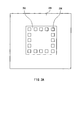
- FIG. 19 illustrates an example of a semiconductor device of the CSP type.
- a semiconductor element 1000 including electrode parts (not shown), and a wiring substrate 1003 including electrodes 1002 for connection with the electrode parts (hereinafter referred to as electrode-part-connection electrodes) are connected electrically via bumps 1001, and the area in which they are connected (hereinafter referred to as connection portion) is encapsulated with a resin forming a resin layer 1004.
- the resin layer 1004 homogeneously disperses stresses occurring due to a difference between the thermal expansion of the semiconductor element 1000 and that of the wiring substrate 1003, thereby preventing the connection portion between the electrode parts and the electrode-part-connection electrodes 1002 from being damaged.
- External electrodes 1005 are provided on a face of the wiring substrate 1003 opposite to the semiconductor element side face thereof.
- a semiconductor device in which electrode parts of a semiconductor element and electrode-part-connection electrodes of a wiring substrate are connected by metal joint via bumps has been disclosed already (see, for instance, in JP 9(1997)-181119 A, and JP 2002-151551 A).
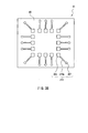
- FIG. 20 shows an example of a semiconductor device manufactured by the wafer level packaging technology.
- a semiconductor element 2000 includes an electronic circuit and electrode pads that are formed on a semiconductor substrate, and bumps 2001 are formed on the electrode pads.
- the bumps 2001 except for ends thereof, are encapsulated with a resin layer 2002, and the ends of the bumps 2001 function as external electrodes.
- the resin layer 2002 functions in the same manner as the resin layer 1004 of the semiconductor device shown in FIG. 19 does (see, for instance, JP 10(1998)-79362 A).
- the conventional semiconductor devices shown in FIGs. 19 and 20 have the following problems.
- the reduction of stresses by the resin layer 1004 or 2002 cannot be regarded as sufficient, and when reliability such as resistance against thermal shock is evaluated, for instance, the resin layers 1004 and 2002 are prone to the cracking.
- the bumps 1001 or 2001 are formed and the connection portion between the semiconductor element and the wiring substrate is encapsulated with the resin layer 1004 or 2002, the manufacturing cost and the number of steps in the manufacturing process increase.
- the semiconductor devices shown in FIGs. 19 and 20 both include bumps 1001 and 2001, respectively, and such a configuration hinders the reduction of the thickness of the semiconductor device.
- a semiconductor device of the present invention includes a semiconductor element including an electrode part, and a wiring substrate including an insulation layer, an electrode-part-connection electrode provided in the insulation layer, and an external electrode that is provided in the insulation layer and that is connected electrically with the electrode-part-connection electrode.
- the electrode part and the electrode-part-connection electrode are connected electrically with each other.
- the insulation layer has an elastic modulus of not less than 0.1 GP a and not more than 5 GPa, and the electrode and the electrode-part-connection electrode are connected by metal bonding.
- a method of the present invention for manufacturing a semiconductor device includes the step of superposing a mounting member and a semiconductor element including an electrode part, the mounting member including an insulation member made of a material containing a resin, an electrode-part-connection electrode provided in the insulation member, and an external electrode provided in the insulation member and connected electrically with the electrode-part-connection electrode, and bonding the electrode part and the electrode-part-connection electrode so that the mounting member and the semiconductor element are integrated.
- the electrode part is prepared so as to include a metal layer
- the electrode-part-connection electrode is prepared so as to include a metal layer
- the metal layer of the electrode part and the metal layer of the electrode-part-connection electrode are connected by metal joint.
- Another method of the present invention for manufacturing a semiconductor device includes the steps of (a) superposing a mounting member and a semiconductor element material including a plurality of semiconductor elements having electrode parts, the mounting member including an insulation member made of a material containing a resin, a plurality of sets of electrode-part-connection electrodes provided on a surface of the insulation member on one side thereof, and a plurality of sets of external electrodes provided on a surface of the insulation member on an opposite side thereof, in which the electrode-part-connection electrodes and the external electrodes are connected electrically with each other, and bonding the electrode parts and the electrode-part-connection electrodes, so that the mounting member and the semiconductor element material are integrated, and (b) cutting the semiconductor element material and the mounting member together so that the individual semiconductor elements are separated from one another.
- the step (b) is carried out after the step (a).
- the electrode parts are prepared so as to include metal layers
- the electrode-part-connection electrodes are prepared so as to include metal layers
- the metal layers of the electrode parts and the metal layers of the electrode-part-connection electrodes are connected by metal joint.
- a semiconductor device of an embodiment of the present invention includes a semiconductor element including an electrode part, and a wiring substrate including an insulation layer, an electrode-part-connection electrode provided in the insulation layer, and an external electrode that is provided in the insulation layer and that is connected electrically with the electrode-part-connection electrode, and the electrode part and the electrode -part-connection electrode are connected electrically with each other.
- the insulation layer has an elastic modulus of not less than 0.1 GPa and not more than 5 GPa, and the electrode and the electrode -part-connection electrode are connected by metal joint.
- the wiring substrate including the insulation layer with an elastic modulus of not less than 0.1 GPa and not more than 5 GPa enables the reduction of stresses occurring due to the thermal expansion difference between the semiconductor element and the wiring substrate. Therefore, connection reliability between the electrode part and the electrode-part-connection electrode can be maintained. Further, since the semiconductor device has a structure such that the electrode part and the electrode-part-connection electrode are bonded directly without a bump, the reduction of the thickness and the cost of the device can be achieved. Thus, with the present embodiment, a thin, low-cost, and highly reliable semiconductor device can be provided.
- the metal joint herein indicates metal-metal solid phase diffusion bonding, or bonding by intermolecular force.
- bonding principles for instance, diffusion by heating (heating method), ultrasonic bonding, room temperature bonding, etc. are available. The bonding principles are described below, with reference to, for instance, a case where the electrode part and the electrode-part-connection electrode include metal layers made of at least one kind of metal selected from the group consisting of noble metals and solder alloys.
- metal atoms composing the metal layer of the electrode part and metal atoms of the metal layer of the electrode-part-connection electrode are diffused in to each other, and a bonding structure in which the electrode part and the electrode-part-connection electrode are connected by metal joint is obtained.
- a contamination layer present at interfaces between the metal layer of the electrode part and the metal layer of the electrode-part-connection electrode is decomposed and removed by the foregoing diffusion.
- an alloy layer is formed by the foregoing diffusion.
- a contamination layer present at interfaces between the metal layer of the electrode part and the metal layer of the electrode-part-connection electrode is decomposed finely by repetitive sliding and expansion.
- the decomposed contamination layer is taken into metallic crystals of each metal layer, whereby a bonding structure in which the electrode part and the electrode-part-connection electrode are connected by metal joint is obtained.
- the metal layer of the electrode part and the metal layer of the electrode-part-connection electrode are brought into contact with each other in a state in which surfaces of the metal layer of the electrode part and the metal layer of the electrode-part-connection electrode are cleaned (oxide films and contamination layers are removed), a bonding structure in which the metal layer of the electrode part and the metal layer of the electrode-part-connection electrode are bonded by the intermolecular force is obtained.
- the semiconductor element includes a plurality of the electrode parts, and a surface of the wiring substrate on a semiconductor element side and a surface of the semiconductor element on a wiring substrate side are bonded with each other so that spaces between the electrode parts are filled with the insulation layer.
- a surface of the wiring substrate crossing a thickness direction of the semiconductor device perpendicularly is larger than a surface of the semiconductor element crossing the thickness direction of the semiconductor device perpendicularly.
- a region where lines for connecting the electrode-part-connection electrodes with the external electrodes are arranged is determined according to the size of the semiconductor element. Therefore, it is difficult to manufacture a semiconductor device of the wafer level package structure employing a semiconductor element having, for instance, not less than 100 pins of electrode parts (pad electrodes), since a rewiring region thereof is small relative to the number of electrode parts thereof.
- a semiconductor element is downsized increasingly as the wiring rules become finer, and the size of a rewiring region thereof is decreased.
- the lines can be provided so as to extend from the electrode parts (pad electrodes) of the semiconductor element to the periphery of the semiconductor element.
- the external electrode may be arranged on a surface of the insulation layer that is seen when the semiconductor device is observed in the thickness direction thereof from a semiconductor element side. This configuration allows the electrode-part-connection electrodes and the external electrodes to be formed at the same time, thereby making it possible to provide a further low-cost semiconductor device.
- the wiring substrate further includes an inner via that is provided in the insulation layer so as to go through the insulation layer in a thickness direction thereof, and the electrode-part-connection electrode and the external electrode are connected electrically through the inner via.
- the wiring substrate preferably further includes at least one wiring layer arranged in the insulation layer. This configuration allows a semiconductor device to be provided with a higher degree of freedom in wiring layout.
- the insulation layer is made of a material containing a thermosetting resin
- the material containing a thermosetting resin contains 75 wt% to 91 wt% of an inorganic filler, and 9 wt% to 25 wt% of a resin composition containing a thermosetting resin.
- the thermosetting resin preferably contains at least one kind of resin selected from the group consisting of epoxy resins, phenol resins, cyanate resins, and thermosetting polyimide.
- the material containing the thermosetting resin preferably contains a thermosetting resin with a glass transition temperature of not higher than 150°C.
- the wiring substrate including the insulation layer made of such a material is capable of reducing stresses occurring due to the thermal expansion difference between the semiconductor element and the wiring substrate, even if the electrode part and the electrode-part-connection electrode are bonded directly by metal joint.
- thermosetting resin contains 75 wt% to 91 wt% of an inorganic filler, and 9 wt% to 25 wt% of a resin composition containing a thermosetting resin is as follows. If the inorganic filler is less than 75 wt%, the thermal expansion coefficient of the insulation layer increases, while the thermal conductivity thereof decreases. If the inorganic filler is more than 91 wt%, the decease in the amount of the thermosetting resin makes it difficult to form the sheet-like material that is to become the insulation layer when it is cured, and the sheet-like material thus formed tends to be torn easily.
- the semiconductor element preferably has a thickness of not less than 30 ⁇ m and not more than 100 ⁇ m. If the semiconductor element has a thickness of not less than 30 ⁇ m and not more than 100 ⁇ m, the semiconductor element has a mechanical characteristic of flexibility.
- This semiconductor element in combination with the wiring substrate including the insulation layer with an elastic modulus of not less than 0.1 GPa and no more than 5 GPa, is capable of reducing stresses that occur due to a thermal expansion difference between the semiconductor element and the wiring substrate, and therefore, enhances the connection reliability of the semiconductor device. It should be noted that the semiconductor element can be processed easily so as to have a desired thickness without damaging the circuit formed on a surface of the semiconductor element as long as the thickness is not less than 30 ⁇ m.
- the insulation layer has a thickness of not less than 30 ⁇ m and not more than 200 ⁇ m. If the thickness thereof is less than 30 ⁇ m, the insulation layer is difficult to handle, whereas if it exceeds 200 ⁇ m, this hinders the thinning of the semiconductor device.
- the semiconductor device preferably has a thickness of not less than 60 ⁇ m and not more than 300 ⁇ m. It is difficult to manufacture a semiconductor device with a thickness of less than 60 ⁇ m, and an excessively great thickness thereof causes the elastic modulus of the semiconductor device as a whole to increase.
- Such a thin semiconductor device with a small elastic modulus as described above enables the reduction of stresses occurring due to the thermal expansion difference between the semiconductor device and a substrate on which the semiconductor device is mounted, and allows the connection reliability of a module incorporating the semiconductor device to increase.
- a method for manufacturing a semiconductor device includes the step of superposing a mounting member and a semiconductor element including an electrode part, the mounting member including an insulation member made of a material containing a resin, an electrode-part-connection electrode provided in the insulation member, and an external electrode provided in the insulation member and connected electrically with the electrode-part-connection electrode, and bonding the electrode part and the electrode-part-connection electrode so that the mounting member and the semiconductor element are integrated.
- the electrode part is prepared so as to include a metal layer
- the electrode-part-connection electrode is prepared so as to include a metal layer
- the metal layer of the electrode part and the metal layer of the electrode-part-connection electrode are connected by metal joint.
- the insulation member in the method of the present embodiment for manufacturing a semiconductor device, in the step, may be formed with a material containing a thermosetting resin in a non-cured state, and the mounting member and the semiconductor element that are superposed are subjected to heat and pressure so that the thermosetting resin is cured.
- the step further preferably includes a sub-step of, after curing the thermosetting resin, heating the metal layer of the electrode part and the metal layer of the electrode-part-connection electrode using ultrasonic vibration.
- the thermosetting resin is cured, the ultrasonic vibration is transmitted easily to the metal layers of the electrode parts and the metal layers of the electrode-part-connection electrodes, whereby metal joint can be obtained with increased bonding strength.
- the metal layer of the electrode part and the metal layer of the electrode-part-connection electrode preferably are formed with at least one kind of metal selected from the group consisting of noble metals and solder alloys.
- the step preferably includes sub-steps of preparing a transfer carrier provided with a wiring pattern, superposing the transfer carrier provided with the wiring pattern and the insulation member so that the wiring pattern and the insulation member are brought into contact with each other, and removing only the transfer carrier from the insulation member, so that the electrode-part-connection electrode is formed on the insulation member.
- the step preferably includes sub-steps of filling a conductive material inside the insulation member, providing the electrode-part-connection electrode on a surface of the insulation member on one side thereof, and providing the external electrode on the other surface of the insulation member on an opposite side thereof, so that the mounting member is formed.
- the step further preferably includes sub-steps of preparing a plurality of sheet-like materials that are made of the material containing a thermosetting resin in a non-cured state, that have through holes, and that are to become the insulation member when they are laminated, filling the conductive material in the through holes, and laminating the sheet-like materials in a manner such that a wiring layer is arranged between the different sheet-like materials, so that the insulation member filled with the conductive material is prepared.
- a semiconductor device can be provided with a higher degree of freedom in wiring layout.
- the method of the present embodiment for manufacturing a semiconductor device preferably further includes a step of processing the semiconductor element so that the semiconductor element has a thickness of not less than 30 ⁇ m and not more than 100 ⁇ m, the processing step being carried out after the mounting and bonding step.
- handling the semiconductor element when thinning the semiconductor element bonded with the wiring substrate is easier than when bonding the previously thinned semiconductor element with the wiring substrate.
- the material containing a thermosetting resin in a non-cured state preferably contains 75 wt% to 91 wt% of an inorganic filler, and 9 wt% to 25 wt% of a resin composition containing a thermosetting resin, and the thermosetting resin preferably contains at least one kind of resin selected from the group consisting of epoxy resins, phenol resins, cyanate resins, and thermosetting polyimide.
- the material containing the thermosetting resin in a non-cured state does not contain thermosetting polyimide
- the material containing the thermosetting resin in a non-cured state preferably contains a thermosetting resin with a glass transition temperature of not higher than 150°C. It should be noted that the content of the inorganic filler and the content of the resin composition containing a thermosetting resin are calculated in terms of a composition that does not contain a solvent.
- Another method of the present embodiment for manufacturing a semiconductor device includes the steps of (a) superposing a mounting member and a semiconductor element material including a plurality of semiconductor elements having electrode parts, the mounting member including an insulation member made of a material containing a resin, a plurality of sets of electrode-part-connection electrodes provided on a surface of the insulation member on one side thereof, and a plurality of sets of external electrodes provided on a surface of the insulation member on an opposite side thereof, wherein the electrode-part-connection electrodes and the external electrodes are connected electrically with each other, and bonding the electrode parts and the electrode-part-connection electrodes, so that the mounting member and the semiconductor element material are integrated, and (b) cutting the semiconductor element material and the mounting member together so that the individual semiconductor elements are separated from one another.
- the step (b) is carried out after the step (a).
- the electrode parts are prepared so as to include metal layers
- the electrode-part-connection electrodes are prepared so as to include metal layers
- the metal layers of the electrode parts and the metal layers of the electrode-part-connection electrodes are connected by metal joint.
- the insulation member in the another method of the present embodiment for manufacturing a semiconductor device, in the step (a), the insulation member may be formed with a material containing a thermosetting resin in a non-cured state, and the mounting member and the semiconductor element material that are superposed are subjected to heat and pressure so that the thermosetting resin is cured.
- the step (a) preferably further includes a sub-step of, after curing the thermosetting resin, heating the metal layers of the electrode parts and the metal layers of the electrode-part-connection electrodes using ultrasonic vibration.
- the ultrasonic vibration is transmitted easily to the metal layers of the electrode parts and the metal layers of the electrode-part-connection electrodes, whereby metal joint can be obtained with increased bonding strength.
- the method of the present embodiment for manufacturing a semiconductor device preferably further includes a step of processing the semiconductor elements so that the semiconductor elements have a thickness of not less than 30 ⁇ m and not more than 100 ⁇ m each, the step being carried out after the step (a) and prior to the step (b). Since the semiconductor elements are processed so as to have a desired thickness before the semiconductor element material is cut into the individual semiconductor elements, this provides high productivity, and facilitates the stress relief step for removing the portions of the semiconductor elements in which stresses remain.
- the metal layers of the electrode parts and the metal layers of the electrode-part-connection electrodes preferably are formed with at least one kind of metal selected from the group consisting of noble metals and solder alloys.
- the step (a) preferably includes sub-steps of preparing a transfer carrier provided with a wiring pattern, superposing the transfer carrier provided with the wiring pattern and the insulation member so that the wiring pattern and the insulation member are brought into contact with each other, and removing only the transfer carrier from the insulation member, so that the electrode-part-connection electrodes are formed on the insulation member.
- the step (a) preferably further includes sub-steps of preparing a plurality of sheet-like materials that are made of the material containing a thermosetting resin in a non-cured state, that have through holes, and that are to become the insulation member when they are laminated, filling a conductive material in the through holes, and laminating the sheet-like materials in a manner such that a wiring layer is arranged between the different sheet-like materials, so that the insulation member filled with the conductive material is prepared.
- This provides a semiconductor device with a high degree of freedom in wiring layout.
- the material containing a thermosetting resin in a non-cured state preferably contains 75 wt% to 91 wt% of an inorganic filler, and 9 wt% to 25 wt% of a resin composition containing a thermosetting resin, and the thermosetting resin preferably contains at least one kind of resin selected from the group consisting of epoxy resins, phenol resins, cyanate resins, and thermosetting polyimide.
- the material containing the thermosetting resin in a non-cured state does not contain thermosetting polyimide
- the material containing the thermosetting resin in a non-cured state preferably contains a thermosetting resin with a glass transition temperature of not higher than 150°C. It should be noted that the content of the inorganic filler and the content of the resin composition containing a thermosetting resin are calculated in terms of a composition that does not contain a solvent.
- a semiconductor device 1 of the present embodiment includes a semiconductor element 103 that includes electrode parts 104, and a wiring substrate 108.
- the wiring substrate 108 includes an insulation layer 101 having an elastic modulus of not less than 0.1 GPa and not more than 5 GPa, electrodes 102 for connection with the electrode parts (hereinafter referred to as electrode-part-connection electrodes) provided in the insulation layer 101, and external electrodes 107 that are provided in the insulation layer 101 and that are connected electrically with the electrode-part-connection electrodes 102.
- the semiconductor element 103 includes a body part 105 (a part including the semiconductor chip) and the electrode parts 104, and the electrode parts 104 protrude out of the body part 105 on the wiring substrate 108 side.
- Each electrode part 104 includes a metal layer 104a
- each electrode-part-connection electrode 102 includes a metal layer 102a.
- the metal layers 104a of the electrode parts 104 and the metal layers 102a of the electrode-part-connection electrodes 102 are connected by metal joint.
- a surface of the wiring substrate 108 perpendicularly crossing a thickness direction of the semiconductor device 1 is larger than a surface of the semiconductor element 103 perpendicularly crossing the thickness direction of the semiconductor device 1.
- the surface of the wiring substrate 108 on the semiconductor element side is larger than the surface of the semiconductor element 103 on the wiring substrate side.
- the external electrodes 107 are disposed in a portion of a surface of the insulation layer 101 on the semiconductor element side where the semiconductor element 103 is not bonded (in a peripheral portion), namely, so as to surround the semiconductor element 103.
- the external electrodes 107 are arranged on the surface of the insulation layer 101 that is seen when the semiconductor device 1 is observed in the thickness direction from the semiconductor element side. As described above, the external electrodes 107 are connected electrically with the electrode-part-connection electrodes 102.
- the wiring substrate 108 including the insulation layer 101 with an elastic modulus of not less than 0.1 GPa and not more than 5 GPa enables the reduction of stresses occurring due to the thermal expansion difference between the semiconductor element 103 and the wiring substrate 108. Therefore, connection reliability can be maintained. Further, since the semiconductor device has a structure such that the electrode parts 104 and the electrode-part-connection electrodes 102 are bonded directly without bumps, the reduction of the thickness and the cost of the device can be achieved. Thus, with the present embodiment, a thin, low-cost, and highly reliable semiconductor device can be provided.
- Metals contained in the metal layers 104a and 102a are not limited particularly, and at least one kind of metal selected from, for instance, noble metals and solder alloys may be contained therein.
- the noble metals include Au, Ag, Cu, Ru, Rb, Pd, Os, Ir, Pt, etc.
- the solder alloys include Pb-Sn, Pb-Ag, Bi-Sn, Zn-Cd, Pb-Sn-Sb, Pb-Sn-Cd, Pb-Sn-In, Bi-Sn-Sb etc.
- the metal layers 104a and 102a preferably are made of Au in particular. This is because stable metal joint can be achieved easily at an interface between Au and Au by application of heat and pressure.
- the semiconductor element 103 includes a plurality of electrode parts 104, and the surface of the wiring substrate 108 on the semiconductor element side and the surface of the semiconductor element 103 on the wring substrate side preferably are bonded so that spaces between the electrode parts are filled with the insulation layer 101.
- This is because, by thus bonding the surface of the wiring substrate 108 on the semiconductor element side and the surface of the semiconductor element 103 on the wiring substrate side in a manner such that the electrode parts 104 and the electrode-part-connection electrodes 102 are embedded in a sheet-like material that is to be the insulation layer 101 after it is cured, stresses occurring due to the thermal expansion difference between the semiconductor element 103 and the wiring substrate 108 can be reduced more effectively.
- a thinner semiconductor device can be provided.
- the insulation layer 101 is required to have an elastic modulus of not less than 0.1 GPa and not more than 5 GPa.
- the elastic modulus exceeds 5 GPa, the stresses occurring due to the thermal expansion difference between the semiconductor element 103 and the wiring substrate 108 cannot be reduced sufficiently by the wiring substrate 108 including the insulation layer 101, which makes it impossible to maintain the connection reliability between the electrode parts 104 and the electrode-part-connection electrode 102.
- the elastic modulus is less than 0.1 GPa, the semiconductor device including such an insulation layer 101 is difficult to handle.
- a material of the insulation layer 101 is not limited particularly as long as the material has an elastic modulus of not less than 0.1 GPa and not more than 5 GPa.
- a material containing a thermosetting resin can be used.
- a mixture of a resin composition containing a thermosetting resin and an inorganic filler, for instance, can be used.
- thermosetting resin a mixture of an inorganic filler and a resin composition containing a thermosetting resin is described below.
- the resin composition preferably contains, as the thermosetting resin, at least one kind of resins selected from the group consisting of epoxy resins, phenol resins, cyanate resins, and thermosetting polyimide. Brominated epoxy resins preferably are used in particular, since they exhibit fire retardance. Further, in the case where the resin composition does not contain thermosetting polyimide, it preferably contains a thermosetting resin having a glass transition temperature (Tg) of not higher than 150°C. In the case where the thermosetting resin contained in the resin composition contains two or more kinds of resins selected from the foregoing group (excluding thermosetting polyimide), at least one kind of a thermosetting resin may have a glass transition temperature (Tg) of not higher than 150°C.
- Tg glass transition temperature
- the resin composition contains thermosetting resins that are categorized as the same kind but have different glass transition temperatures (Tg), for instance, two kinds of epoxy resins having different glass transition temperatures (Tg), these resins are regarded as resins of different kinds, and at least one kind of an epoxy resin among the foregoing two or more kinds of epoxy resins may have a glass transition temperature of not higher than 150°C. It should be noted that no lower limit of the glass transition temperature is set particularly, but normally, the glass transition temperature preferably is not lower than 50°C.
- thermosetting resin having a glass transition temperature of not higher than 150°C and the other resins is not limited particularly, but normally the ratio by weight preferably is 1:3 to 3:1.
- the foregoing resin composition further may contain a curing agent or a curing accelerator.
- a curing agent for instance, a bisphenol-A type Novolac resin and imidazole can be used as the curing agent and the curing accelerator, respectively.
- the foregoing resin composition may further contain an additive such as a dispersant, a colorant, a coupling agent, a mold releasing agent, etc.
- Examples usable as a solvent for decreasing the viscosity of a mixture that contains an inorganic filler and a resin composition containing a thermosetting resin include ethyl carbitol, butyl carbitol, and butyl carbitol acetate. These have boiling points of not lower than 150°C. Additionally, the examples include methyl ethyl ketone, isopropanol, toluene, etc. These have boiling points of not higher than 100°C. One kind, or two or more kinds of these solvents may be used.
- the foregoing solvent is unnecessary if it is possible, without mixing the solvent in the mixture of the inorganic filler and the resin composition containing the thermosetting resin, to embed the electrode parts 104 and the electrode-part-connection electrodes 102 in a sheet-like material that is to become the insulation layer 101 when it is cured in the manufacturing process of the semiconductor device of the present embodiment.
- the inorganic filler As the inorganic filler, at least one kind selected from the group consisting of, for instance, Al 2 O 3 , MgO, SiO 2 , BN, and AlN can be used. These are preferred since they have high thermal conductivities.
- the inorganic filler preferably has a particle diameter of not less than 0.1 ⁇ m and not more than 100 ⁇ m. If the particle diameter is excessively small or large, the filling factor of the inorganic filler in the insulation layer 101 decreases, thereby causing the thermal conductivity of the insulation layer 101 to decrease. Further, it also causes the difference of a coefficient of thermal expansion of the insulation layer 101 from that of the semiconductor element 103.
- the content of the inorganic filler preferably is 75 wt% to 91 wt%. If it is less than 75 wt%, the coefficient of thermal expansion of the insulation layer 101 increases, while the thermal conductivity thereof decreases. On the other hand, if it is more than 91 wt%, the decease in the amount of the thermosetting resin makes it difficult to form the sheet-like material that is to become the insulation layer 101 when it is cured, and the sheet-like material thus formed tends to be torn easily.
- the content of the inorganic filler is 75 wt% to 91 wt%
- the content of the resin composition in the mixture of the inorganic filler and the resin composition containing a thermosetting resin is 9 wt% to 25 wt%. It should be noted that the content of the inorganic filler in the insulation layer and the content of the resin composition containing a thermosetting resin in the insulation layer are determined on the basis of a composition that does not contain a solvent.
- the more preferable content of the inorganic filler is 80 wt% to 88 wt%. With this content, the sheet-like material that is to become the insulation layer can be formed easily, and the wiring substrate 108 having a high thermal conductivity can be obtained.
- the content of the resin composition containing a thermosetting resin is 12 wt% to 20 wt%.
- the mixture of the inorganic filler and the resin composition containing a thermosetting resin preferably does not contain a reinforcer such as glass fiber. This is because, in the case where a reinforcer is not contained, the wiring substrate 108 having a low elastic modulus can be obtained easily. Even without such a reinforcer, it is possible to maintain a mechanical strength of the insulation layer 101, since the inorganic filler is filled at a high density.
- the insulation layer 101 preferably has a thickness of not less than 30 ⁇ m and no less than 200 ⁇ m. If the thickness is less than 30 ⁇ m, the insulation layer 101 is difficult to handle, and if the thickness is more than 200 ⁇ m, the semiconductor device has an excessive thickness. Further, the thickness more preferably is not less than 50 ⁇ m and not more than 150 ⁇ m. The thickness in this range is preferred from the viewpoints of handlability, thickness, and elasticity.
- the electrode-part-connection electrodes 102 can be made of a material having electrical conductivity, for instance, a copper foil or a conductive resin composition. Examples of a method for forming the electrode-part-connection electrodes 102 include the subtractive method, the additive method, etc.
- the electrode-part-connection electrodes 102 including the metal layers 102a, for instance, Au layers are formed through, for instance, the following process. First, a copper foil is laminated on the sheet-like material that is to become the insulation layer 101, and after the application of pressure thereto, unnecessary portions of the copper foil are removed. Thereafter, the copper foil is subjected to electroless plating.
- the external electrodes 107 also can be formed with a material having electrical conductivity, for instance, a copper foil, a conductive resin composition, etc., like the electrode-part-connection electrodes 102, and they can be formed through the same process as that for the electrode-part-connection electrodes 102.
- the electrode-part-connection electrodes 102 are formed on one of the surfaces of the sheet-like material that is to become the insulation layer 101, and the external electrodes 107 also are formed on the foregoing surface of the sheet-like material. Therefore, the electrode-part-connection electrodes 102 and the external electrodes 107 can be formed at the same time.
- the semiconductor device of the present embodiment is not limited to this configuration.
- the surface of the semiconductor element 103 (surface of the body part 105) may be bonded with the insulation layer 101 by embedding the surface of the semiconductor element 103 on the wiring substrate side into the sheet-like material that is to become the insulation layer 101 after it is cured.
- the body part 105 of the semiconductor element 103 may be embedded in the insulation layer 101.
- each of the electrode parts 104 and the electrode-part-connection electrodes 102 has a structure that includes, for instance, a copper foil or a conductive resin composition, and an Au layer formed on its surface by plating, their configuration is not limited to this.
- an entirety of each of the same may be made of, for instance, a noble metal such as Au, a solder alloy, or the like.
- FIG. 2A is a plan view illustrating a state in which a semiconductor device of the present embodiment is mounted on a motherboard 206
- FIG. 2B is a cross-sectional view of the same
- FIGs. 3A and 3B are views illustrating steps of an example of a manufacturing process of the semiconductor device shown in FIGs. 2A and 2B.
- a semiconductor device of the present embodiment includes a semiconductor element 203 including electrode parts 204, and a wiring substrate 208.
- the wiring substrate 208 includes an insulation layer 201 having an elastic modulus of not less than 0.1 GPa and not more than 5 GPa, electrode-part-connection electrodes 202 provided on one of surfaces of the insulation layer 201, and external electrodes 207 that are connected electrically with the electrode-part-connection electrodes 202.
- the external electrodes 207 are arranged on the same surface of the insulation layer 201 where the electrode-part-connection electrodes 202 are arranged, as in Embodiment 1.
- Each of the electrodes parts 204 and the electrode-part-connection electrodes 202 includes a metal layer, and when the electrode parts 204 and the electrode-part-connection electrodes 202 are superposed, their metal layers are in contact with each other. It should be noted that in FIGs. 2A and 2B, the illustration of the metal layers of the electrode parts 204 and the metal layers of the electrode-part-connection electrodes 202 is omitted.
- the semiconductor device of the present embodiment also, as in Embodiment 1, is configured so that the wiring substrate 208 includes the insulation layer 201 having an elastic modulus of not less than 0.1 GPa and not more than 5 GPa. Therefore, even if the electrode parts 204 and the electrode-part-connection electrodes 202 are connected directly by metal joint, not via bumps, the wiring substrate 208 including the insulation layer 201 with an elastic modulus of not less than 0.1 GPa and not more than 5 GPa enables the reduction of stresses occurring due to the thermal expansion difference between the semiconductor element 203 and the wiring substrate 208. Therefore, connection reliability can be maintained between the electrode parts 204 and the electrode-part-connection electrodes 202. Thus, with the present embodiment, a thin, low-cost, and highly reliable semiconductor device can be provided.
- the insulation layer 201 has a thickness of approximately 15 ⁇ m to 40 ⁇ m, it is possible to provide an extremely thin semiconductor device.
- thermoplastic polyimide film a thermosetting resin film, etc.
- thermosetting resin film a thermoplastic polyimide film, a thermosetting resin film, etc.
- thermosetting resin is identical to the thermosetting resin of Embodiment 1 described above that is contained in the mixture of a resin composition containing a thermosetting resin and an inorganic filler.
- the electrode-part-connection-electrodes 202 and the external electrodes 207 are formed with the same materials through the same process as those of Embodiment 1 described above.
- the bonding of the wiring substrate 208 with the semiconductor element 203 preferably is carried out as follows. First, a coupling treatment is applied to a surface of the semiconductor element 203, and an insulation resin 209 is supplied to the surface of the semiconductor element 203 thus subjected to the coupling treatment. Thereafter, the semiconductor element 203 and the wiring substrate 208 are bonded with each other. This process enhances the adhesion between the semiconductor element 203 and the wiring substrate 208.
- the coupling treatment is carried out by dissolving a coupling agent in a solvent so as to have a concentration of 0.1 wt% to 2 wt%, applying the solution over the semiconductor element 203, and drying the same.
- the application of the solution can be carried out by immersion, spraying, etc.
- the coupling agents include aminosilane, epoxysilane, acrylsilane, mercaptosilane, vinylsilane, etc.
- insulation resin examples include, for instance, photosensitive polyimide.
- the bonding of the semiconductor element 203 with the wiring substrate 208 can be carried out by bonding a film including a thermosetting resin in a non-cured state with the electrode-part-connection electrodes 202 and the external electrode 207 formed therein onto the semiconductor element 203 by thermocompression by using a vacuum laminator or the like, and curing the thermosetting resin.
- the semiconductor device of Embodiment 2 also can be manufactured through the following process.
- a semiconductor element 203 provided with electrode parts 204 is prepared, and is attached to a predetermined location on the motherboard 206.
- a mounting member 91 that includes an insulation member 90, electrode-part-connection electrodes 202 arranged on a surface of the insulation member 90 on one side thereof, and external electrodes 207 connected electrically with the electrode-part-connection electrodes 202 is prepared. It should be noted that in FIG. 3A, the illustration of wiring of the motherboard 206 is omitted, and in FIG.
- 210a denotes a line that connects one of the electrode-part-connection electrodes 202 with a corresponding one of the external electrodes 207 and that is included in a wiring layer 210 that includes the electrode-part-connection electrodes 202 and the external electrodes 207.
- the mounting member 91 and the motherboard 206 on which the semiconductor element 203 is attached are laminated so that the electrode parts 204 and the electrode-part-connection electrodes 202 are brought into contact with each other.
- the mounting member 91 and the semiconductor element 203 are bonded with each other, and the external electrodes 207 and the motherboard 206 are connected with each other.
- the metal layers of the electrodes parts 204 and the metal layers of the electrode-part-connection electrodes 202 are heated using an ultrasonic vibrator so that the electrode parts 204 and the electrode-part-connection electrodes 202 are connected by metal joint.
- the mounting member 91 bonded with the semiconductor element 203 becomes a wiring substrate 208, while the insulation member 90 becomes an insulation layer 201 (see FIGs. 2A and 2B).
- the insulation member 90 is, for instance, a thermoplastic polyimide film or the like
- a coupling treatment is applied to a surface of the semiconductor element 203, and an insulation resin 209 is supplied to the surface of the semiconductor element 203 thus subjected to the coupling treatment. Thereafter, the mounting member 91 and the semiconductor element 203 are bonded with each other.
- the insulation member 90 is, for instance, a film containing a thermosetting resin in a non-cured state, the film is heated while pressure is applied thereto partially, so that the mounting member 91 and the semiconductor element 203 are bonded with each other.
- the mounting member 91 is a film containing a thermosetting resin in a non-cured state
- the mounting member 91 shrinks upon application of heat and pressure and therefore, it is possible to eliminate slack of the mounting member 91 (the insulation layer 201) between the electrode-part-connection electrodes 202 and the external electrodes 207.
- the semiconductor device of the present embodiment is completed, while the semiconductor device of the present embodiment is connected with the motherboard 206.
- a semiconductor device 3 of the present embodiment includes a semiconductor element 303 including electrode parts 304, and a wiring substrate 308.
- the wiring substrate 308 includes an insulation layer 301 having an elastic modulus of not less than 0.1 GPa and not more than 5 GPa, electrode-part-connection electrodes 302 provided in the insulation layer 301, and external electrodes 307 that are provided in the insulation layer 301 and that are connected electrically with the electrode-part-connection electrodes 302.
- Each electrode part 304 includes a metal layer 304a, and each electrode-part-connection electrode 302 includes a metal layer 302a.
- the metal layers 304a of the electrode parts 304 and the metal layers 302a of the electrode-part-connection electrodes 302 are connected by metal joint.
- the wiring substrate 308 including the insulation layer 301 with an elastic modulus of not less than 0.1 GPa and not more than 5 GPa enables the reduction of stresses occurring due to the thermal expansion difference between the semiconductor element 303 and the wiring substrate 308. Therefore, connection reliability can be maintained between the electrode parts 304 and the electrode-part-connection electrodes 302. Further, since the semiconductor device has a structure such that the electrode parts 304 and the electrode-part-connection electrodes 302 are bonded directly without bumps, the reduction of the thickness and the cost of the device can be achieved.
- a thin, low-cost, and highly reliable semiconductor device can be provided. Still further, in the semiconductor device 3, as in Embodiment 1, since the surface of the wiring substrate 308 on the semiconductor element side and the surface of the semiconductor element 303 on the wiring substrate side are bonded with each other in a manner such that spaces between the electrode parts 304 are filled with the insulation layer 301, stresses occurring due to the thermal expansion difference between the semiconductor element and the wiring substrate can be reduced.
- the electrode-part-connection electrodes 302 are provided in the insulation layer 301, and the external electrodes 307 are provided on a surface 301b of the insulation layer 301 that is opposite to a surface 301a thereof on the semiconductor element side.
- the electrode-part-connection electrodes 302 and the external electrodes 307 are connected electrically with each other through inner vias 309 that are provided in the insulation layer 301 so as to go through the insulation layer 301 in a thickness direction thereof.
- the semiconductor device can be downsized. It should be noted that since the surface of the wring substrate 308 on the semiconductor element side is larger than the surface of the semiconductor element 303 on the wiring substrate side in the example shown in FIG. 4, a periphery of the wiring substrate 308 protrudes out of the semiconductor element 303, but the protruded portion desirably is reduced as much as possible from the viewpoint of downsizing the semiconductor device.
- the inner vias 309 are made of a conductive material, for instance, a conductive resin composition, and as such a conductive resin composition, for instance, a conductive paste containing a metal powder, a thermosetting resin, and a curing agent can be used.
- a conductive resin composition for instance, a conductive paste containing a metal powder, a thermosetting resin, and a curing agent can be used.
- the metal powder for instance, at least one kind of metal selected from the group consisting of gold, silver, copper, palladium, and nickel is used preferably.
- the electrode-part-connection electrodes 302 and the external electrodes 307 can be connected electrically with a low resistance.
- the thermosetting resin and the curing agent for instance, an epoxy resin and imidazol can be used, respectively.
- the semiconductor element 303 has a mechanical characteristic of flexibility since the semiconductor element 303 has a thickness of not less than 30 ⁇ m and not more than 100 ⁇ m.
- This semiconductor element 303 in combination with the wring substrate 308 including the insulation layer 301 with an elastic modulus of not less than 0.1 GPa and no more than 5 GPa, is capable of reducing stresses that occur due to a thermal expansion difference between the semiconductor element 303 and the wiring substrate 308, and therefore, enhances the connection reliability of the semiconductor device. It should be noted that the semiconductor element 303 can be processed easily so as to have a desired reduced thickness without damaging the circuit formed on a surface of the semiconductor element 303 as long as the thickness is not less than 30 ⁇ m.
- an overall thickness of the semiconductor device can be set to be not less than 60 ⁇ m and not more than 300 ⁇ m.
- the semiconductor device as a whole is made more flexible, and the connection reliability of a module in which such a semiconductor device 3 is mounted can be enhanced.
- the semiconductor device 3 is suitable as a component for use in a circuit component built-in module that incorporates a circuit component in a substrate thereof.
- the semiconductor device 4 includes a semiconductor element 403 including electrode parts 404, and a wiring substrate 408.
- Metal layers 404a of the electrode parts 404 and metal layers 402a of electrode-part-connection electrodes 402 are connected by metal joint.
- the wiring substrate 408 includes: an insulation layer 401 that includes an upper insulation layer 401a and a lower insulation layer 401b and that has an elastic modulus of not less than 0.1 GPa and no more than 5 GPa; electrode-part-connection electrodes 402 provided in the insulation layer 401; and external electrodes 407 that are provided on a surface 401d of the insulation layer 401 opposite to a surface 401c thereof on the semiconductor element 403 side. Further, the wiring substrate 408 includes a wiring layer 410 arranged between the upper insulation layer 401a and the lower insulation layer 401b, and inner vias 409a and 409b that connect electrically the electrode-part-connection electrodes 402 with the external electrodes 407.
- the wiring substrate 408 has a multilayer wiring structure.
- the degree of freedom in wiring layout can be increased further.
- the external electrodes 407 can be arranged in an area array style, the semiconductor device can be downsized.
- the wiring substrate 408 including the insulation layer 401 with an elastic modulus of not less than 0.1 GPa and not more than 5 GPa enables the reduction of stresses occurring due to the thermal expansion difference between the semiconductor element 403 and the wiring substrate 408. Therefore, connection reliability can be maintained between the electrode parts 404 and the electrode-part-connection electrodes 402. Further, since the semiconductor device has a structure such that the electrode parts 404 and the electrode-part-connection electrodes 402 are bonded without bumps, the reduction of the thickness and the cost of the device can be achieved. Thus, with the present embodiment, a thin, low-cost, and highly reliable semiconductor device can be provided.
- the semiconductor device 4 is, as in Embodiments 1 and 3, configured so that the surface of the wiring substrate 408 on the semiconductor element side and the surface of the semiconductor element 403 on the wiring substrate side are bonded with each other in a manner such that spaces between the electrode parts 404 are filled with the insulation layer 401, stresses occurring due to the thermal expansion difference between the semiconductor element 403 and the wiring substrate 408 can be reduced more effectively.
- an overall thickness of the semiconductor device can be set to be not less than 90 ⁇ m and not more than 300 ⁇ m.
- the connection reliability of a module in which such a semiconductor device 4 is mounted can be enhanced, and the semiconductor device 4 is suitable as a component for use in a circuit component built-in module.
- the surface of the wring substrate 408 on the semiconductor element side is larger than the surface of the semiconductor element 403 on the wiring substrate side in the example shown in FIG. 5A, a periphery of the wiring substrate 408 protrudes out of the semiconductor element 403, but the protruded portion desirably is reduced as much as possible from the viewpoint of downsizing the semiconductor device.
- the wiring substrate 408 is configured so that one wiring layer 410 is provided in the insulation layer 401 in the semiconductor device 4, the wiring substrate 408 is not limited to this configuration. Two or more wiring layers may be provided in the insulation layer 401.
- the semiconductor device 4 shown in FIG. 5A has a land grid array (LGA) structure
- the semiconductor device of the present embodiment may have the ball grid array (BGA) structure as shown in FIG. 5B.
- the semiconductor device in the case where the semiconductor element 403 has an area (an area of a surface thereof crossing the thickness direction perpendicularly) of not less than 5 mm 2 , for instance, approximately 10 mm 2 , the semiconductor device preferably has the BGA structure, which is excellent in secondary mounting with respect to a motherboard.
- the LGA structure FIG. 5A is preferable.
- the semiconductor device 5 includes a semiconductor element 503 including electrode parts 504, and a wiring substrate 508.
- the wiring substrate 508 has a multilayer wiring structure including: an insulation layer 501 that includes an upper insulation layer 501a and a lower insulation layer 501b and that has an elastic modulus of not less than 0.1 GPa and no more than 5 GPa; electrode-part-connection electrodes 502 provided in the insulation layer 501; external electrodes 507 that are provided on a surface 501d of the insulation layer 501 opposite to a surface 501c thereof on the semiconductor element 503 side; and a wiring layer 510 arranged in the insulation layer 501.
- Each electrode part 504 and each electrode-part-connection electrode 502 includes a metal layer 504a and a metal layer 502a, respectively, and in the semiconductor device 5, the metal layers 504a of the electrode parts 504 and the metal layers 502a of the electrode-part-connection electrodes 502 are connected by metal joint.
- the wiring substrate 508 including the insulation layer 501 with an elastic modulus of not less than 0.1 GPa and not more than 5 GPa enables the reduction of stresses occurring due to the thermal expansion difference between the semiconductor element 503 and the wiring substrate 508. Therefore, connection reliability can be maintained. Further, since the semiconductor device has a structure such that the electrode parts 504 and the electrode-part-connection electrodes 502 are bonded directly without bumps, the reduction of the thickness and the cost of the device can be achieved. Thus, with the present embodiment, a thin, low-cost, and highly reliable semiconductor device can be provided.
- the semiconductor device 5 is manufactured by a so-called wafer level packaging technology whereby a plurality of semiconductor elements are packaged together at a wafer level, and an area of a surface of the wiring substrate 508 on the semiconductor element side (an area of a surface thereof crossing the thickness direction perpendicularly) and an area of a surface of the semiconductor element 503 on the wiring substrate side (an area of a surface thereof crossing the thickness direction perpendicularly) are equal to each other. Therefore, the degree of freedom in wiring layout is inferior to that of the semiconductor device 4 of Embodiment 4, but a further downsized semiconductor device can be provided.
- the wiring substrate 508 is configured so that one wiring layer 510 is provided in the insulation layer 501 in the present embodiment, the wiring substrate is not limited to this configuration. It may be configured, without including a wiring layer inside, so that the electrode-part-connection electrodes 504 and the external electrodes 507 are connected directly through inner vias arranged in the insulation layer 501. Alternatively, two or more wiring layers may be provided in the insulation layer 501.
- FIGs. 7A and 8A are plan views of the semiconductor device of the present embodiment
- FIGs. 7B and 8B are cross-sectional views of the semiconductor device of the present embodiment.
- a semiconductor device 6 of the present embodiment is identical to the semiconductor device of Embodiment 4 (FIG. 5B) except that two wiring layers 610 are provided in an insulation layer.
- 603 denotes a semiconductor element
- 604 denotes an electrode part of the semiconductor element 603
- 608 denotes a wiring substrate
- 602 denotes an electrode-part-connection electrode
- 607 denotes an external electrode
- 601 denotes an insulation layer
- 610 denotes a wiring layer
- 610a denotes a line composing the wiring layer 610
- 609 denotes an inner via.
- the illustration of metal layers included in the electrode parts 604 and metal layers included in the electrode-part-connection electrodes 602 is omitted.
- a region where lines for connecting the electrode-part-connection electrodes with the external electrodes are arranged is determined according to the size of the semiconductor element. Therefore, it is difficult to manufacture a semiconductor device of the wafer level package structure employing a semiconductor element having, for instance, not less than 100 pins of electrode parts (pad electrodes), since a rewiring region thereof is small relative to the number of electrode parts thereof. Besides, in recent years, a semiconductor element is downsized increasingly as the minimum conductive unit width, etc., determined according to the wiring rule is narrowed, and the size of a rewiring region thereof is decreased. As shown in FIGs.
- the lines 610a can be provide so as to extend from the electrode parts (pad electrodes) 604 of the semiconductor element 603 to the periphery of the semiconductor element 603.
- a semiconductor device employing a semiconductor element having a greater number of electrode parts (pad electrodes) 604 can be provided.
- FIG. 7B in the case where many lines 610a are provided on a surface of the insulation layer 601 on the semiconductor element side, it is preferable to provide as many lines 610a on a surface of the insulation layer 601 that is seen when the semiconductor device 6 is observed in the thickness direction of the semiconductor device 6 from the semiconductor element 603 side as possible, that is, on an area of the surface of the insulation layer 601 that is not in contact with the semiconductor element 603. It should be noted that without providing many wires on the surface of the insulation layer 610 on the semiconductor element side, lines can be provided in the insulation layer 601 freely, as shown in FIG. 8B. Either the structure shown in FIGs. 7A and 7B or the structure shown in FIGs. 8A and 8B is selected according to the purpose of use.
- Embodiment 7 relates to a method for manufacturing the semiconductor device 1 of Embodiment 1 described above, which is described below with reference to FIGs. 9A to 9E.
- the semiconductor element 103 including the electrode parts 104 is prepared.
- the electrode parts 104 protrude from a surface of the body part 105 on one side (a surface thereof to be bonded with the wiring substrate), and include the metal layers (Au layers) 104a.
- the metal layers 104 are formed by plating.
- a sheet-like insulation member 30 is formed using a material containing a thermosetting resin in a non-cured state through a process described below.
- the material containing a thermosetting resin in a non-cured state is identical to the material of the insulation layer of Embodiment 1 described above.
- the material containing a thermosetting resin in a non-cured state contains, in terms of a composition containing a solvent, for instance, 73.8 wt% to 91 wt% of an inorganic filler, 8.8 wt% to 25 w% of a resin composition containing a thermosetting resin, and 0.2 wt% to 1.2 wt% of a solvent.
- a mixture slurry containing an inorganic filler, a resin composition containing a thermosetting resin, a solvent having a boiling point of not lower than 150°C, and a solvent having a boiling point of not higher than 100°C is prepared, and a film is formed with this mixture slurry on a releasing film (not shown).
- the method for forming the film is not limited particularly, and examples of the same include doctor blading, coater method, extrusion, etc.
- only the solvent having a boiling point of not higher than 100°C is removed by drying from the film thus formed. By so doing, the insulation member 30 in a non-cured state having flexibility is formed.
- the wiring pattern 31 includes the electrode-part-connection electrodes and the external electrodes (see FIG. 1).
- Examples of the method for forming the wiring pattern 31 include the subtractive method, transferring, and the additive method.
- a copper foil with a thickness of 9 ⁇ m is laminated on a surface 30a of the insulation member 30 on one side thereof at 100°C, and after pressure application thereto, unnecessary portions thereof are removed, whereby a wiring pattern 31b is formed. Thereafter, it is subjected to electroless plating so that the protruded wiring pattern 31 including metal layers (Au layers) 31a is formed. Thus, a mounting member 32 as shown in FIG. 9C is formed.
- the pressure applied upon the metal joint of the metal layers 102a of the electrode-part-connection electrodes 102 and the metal layer 104a of the electrode parts 104 is applied accurately to an interface where the electrode-part-connection electrodes 102 and the electrode parts 104 are in contact with each other. Therefore, the electrode-part-connection electrodes 102 and the electrode parts 104 are bonded firmly with each other (see FIG. 1).
- the insulation member 30 has to be immersed in chemical solutions after the wiring pattern 31b is formed by removing unnecessary portions from the copper foil, and after the metal layers (Au layers) 31a are formed by electroless plating. Therefore, after immersing the insulation member 30 in chemical solutions, it is necessary to perform the water washing and drying of the insulation member 30 sufficiently.
- the mounting member 32 and the semiconductor element 103 are superposed on each other so that the electrode parts 104 and predetermined portions of the wiring pattern 31 are in contact with each other, and surfaces at which the metal layers (Au layers) 104a of the electrode parts 104 and the metal layers (Au layers) 31a of the wiring pattern 31 are in contact with each other are bonded by metal joint by heating the same with supersonic vibration, while pressure is applied thereto in the thickness direction.
- the mounting member 32 since the mounting member 32 is in the non-cured state, the ultrasonic wave tends to be absorbed easily by the mounting member 32. Therefore, it is necessary to increase the frequency of the vibration.
- surfaces of the electrode parts 104 and the wiring pattern 31 preferably are subjected to plasma cleaning so as to be cleaned.
- the laminate composed of the mounting member 32 and the semiconductor element 103 is heated and subjected to pressure in its thickness direction so that portions of the wiring pattern 31 bonded with the electrode parts 104 (electrode-part-connection electrodes) and the electrode parts 104 are embedded in the insulation member 30, and the insulation member 30 is cured.
- the semiconductor element 103 and the mounting member 32 are bonded with each other.
- the releasing film (not shown) is removed from the cured insulation member 30.
- the cured insulation member 30 becomes the insulation layer 101
- the mounting member 32 becomes the wiring substrate 108.
- the portions of the wiring pattern 31 that are bonded with the electrode parts 104 and embedded in the insulation layer 101 are the electrode-part-connection electrodes 102, and the external electrodes 107 are included in portions of the wiring pattern 31 that are not bonded with the semiconductor element 103.
- the wiring pattern 31 is formed so as to protrude from the surface 30a of the insulation member 30 on one side, but the configuration thereof is not limited to this.
- the wiring pattern 31 may be embedded in the insulation member 30 so that a surface including the wiring pattern 31 and the surface 30a of the insulation member 30 on one side is substantially flat as shown in FIG. 10A, or alternatively, the wiring pattern 31 may be embedded partially in the insulation member 30, as shown in FIG. 10B.
- a transfer carrier provided with the wiring pattern 31 thereon and the insulation member 30 are aligned and superposed on each other, and the wiring pattern 31 is transferred onto the insulation member 30 so that an entirety or a part of the wring pattern 31 is embedded in the insulation member 30.
- the semiconductor element 103 and the mounting member 32 are brought into close contact with each other, whereby the electrode-part-connection electrodes 102 and the electrode parts 104 are embedded in the insulation member 30 (see FIG. 9E).
- the semiconductor element 103 thus includes a plurality of electrode parts 104, and the semiconductor element 103 and the wiring substrate 108 are bonded with each other in a manner such that spaces between the electrode parts are filled with the insulation layer 101, stresses occurring due to the thermal expansion difference between the semiconductor element and the wiring substrate are reduced more effectively, whereby a thinner semiconductor device can be provided.
- the metal layers 104a of the electrode parts 104 and the metal layer 31a of the wiring pattern 31 may be heated using ultrasonic vibration.
- ultrasonic wave By applying ultrasonic wave after the thermosetting resin is cured, the ultrasonic vibration is transmitted easily to the metal layers 104a of the electrode parts 104 and the metal layers 31a of the wiring pattern 31, whereby metal joint can be carried out easily and stably.
- the present embodiment relates to a method for manufacturing the semiconductor device 3 shown in FIG. 4, which is described below with reference to FIGs. 11A to 11F, and 12A and 12B.
- the semiconductor element 303 including the electrode parts 304 is prepared.
- the electrode parts 304 protrude from a surface of a body part on one side, and include the metal layers (Au layers) 304a.
- the metal layers 304a are formed by plating.
- a sheet-like insulation member 40 is formed using a material containing a resin composition containing a thermosetting resin in a non-cured state and an inorganic filler.
- the material containing a resin composition containing a thermosetting resin in a non-cured state and an inorganic filler is identical to the material of the insulation layer of Embodiment 1 described above.
- through holes 41 are formed in the insulation member 40.
- the through holes 41 are formed by, for instance, laser processing using carbon dioxide laser, excimer laser, or the like, drilling, punching, etc.
- the laser processing is particularly preferable since it is easy and highly accurate.
- a conductive material such as a conductive resin composition 42 is filled in the through holes 41.
- the conductive resin composition 42 is identical to the material of the inner vias of Embodiment 3 described above.
- transfer carriers 45 and 46 provided with wiring patterns 43 and 44, respectively are prepared.
- the transfer carriers 45 and 46 are, for instance, resin films or metal foils.
- the wiring patterns 43 and 44 are formed with a material identical to that of the electrode-part-connection electrodes and that of the external electrodes of Embodiment 1 described above.
- the wiring pattern 43 is obtained by, for instance, first, preparing the transfer carrier 45 having recesses 45a, then, forming Au layers 43a in the recesses 45a, and thereafter forming Cu layers 43b thereon. Both of the Au layers 43a and the Cu layers 43b can be formed by the additive method.
- the electrode-part-connection electrodes that include metal layers and protrude out of the insulation member 40 can be formed by superposing the insulation member 40 and the transfer carrier 45 in a manner such that a surface 40a of the insulation member 40 on one side thereof and the wiring pattern 43 face each other, and removing only the transfer carrier 45 while leaving the wiring pattern 43 on the insulation member 40.
- this method does not require, for instance, the step of immersing the insulation member 40 in a chemical solution, which is necessary in the process of manufacturing a semiconductor device according to Embodiment 7. Therefore, the steps of washing with water and drying the insulation member 40 thus immersed in a chemical solution are unnecessary also. Thus, the process can be simplified.
- the wiring pattern 44 is formed by, for instance, the subtractive method of laminating a copper foil on a surface of the transfer carrier 46 on one side, applying pressure thereto, and thereafter removing unnecessary portions of the copper foil.
- the transfer carriers 45 and 46 provided with the wiring patterns 43 and 44, respectively, and the insulation member 40 are aligned and superposed, and the laminate thus obtained is heated in an atmosphere at approximately 100°C to 120°C while a pressure of 3 MPa to 10 MPa is applied thereto, so that the wiring patterns 43 and 44 are transferred to the insulation member 40.
- a mounting member 47 which has the electrode-part-connection electrodes 302 including the metal layers (Au layers) 302a provided on the surface 40a of the insulation member 40 on one side thereof, and the external electrodes 307 provided on a surface 40b of the insulation member 40 on an opposite side thereof, and contains a thermosetting resin in a non-cured state (see FIG. 11F).
- the semiconductor element 303 and the mounting member 47 are superposed so that the electrode parts 304 and the electrode-part-connection electrodes 302 are brought into contact with each other, and while applying pressure thereto in the thickness direction, surfaces at which the metal layers (Au layers) 304a of the electrodes parts 304 and the metal layers (Au layers) 302a of the electrode-part-connection electrodes 302 are brought into contact with each other are heated using ultrasonic vibration so as to be bonded.
- ultrasonic wave tends to be absorbed by the mounting member 47. Therefore, the frequency of vibration has to be increased.
- the electrode-part-connection electrodes 302 and the electrode parts 304 are embedded in the insulation member 40, and the insulation member 40 and the conductive resin composition 42 are cured, whereby the semiconductor element 303 and the mounting member 47 are bonded with each other.
- the cured insulation member 40 becomes the insulation layer 301
- the cured conductive resin composition 42 becomes inner vias 309
- the mounting member 47 becomes the wiring substrate 308.
- the wiring pattern 43 is formed using the transfer carrier 45 having recesses 45a at predetermined positions, the configuration is not limited to this.
- a protruded wiring pattern 43 may be formed on the transfer carrier 45 having a flat surface.
- the Au layers 43a and the Cu layers 43b are formed by, for instance, the subtractive method.
- the transfer carrier 45 provided with the wiring pattern 43 and the insulation member 40 are aligned and superposed, and the wiring pattern 43 is transferred onto the insulation member 40 in a manner such that an entirety or a part of the wiring pattern 43 is embedded in the insulation member 40.
- the semiconductor device 6 of Embodiment 6 can be manufactured by the semiconductor device manufacturing method according to the present embodiment.
- the present embodiment relates to an example of a method for manufacturing the semiconductor device 4 shown in FIG. 5A, which is described below with reference to FIGs. 14A to 14G, and 15A and 15B.
- the semiconductor element 403 including the electrode parts 404 is prepared.
- the electrode parts 404 protrude from a surface of a body part on one side thereof (a surface to be bonded with the wiring substrate of the semiconductor element 403), and include the metal layers (Au layers) 404a.
- the metal layers 404a are formed by plating.
- a first sheet-like material 50 having through holes 51 is formed using a material containing a resin composition containing a thermosetting resin in a non-cured state and an inorganic filler. Then, the through holes 51 are filled with a conductive resin composition 52b, whereby a second sheet-like material 53 is formed.
- the material of the first sheet-like material 50 is the same as the material of the insulation layer of Embodiment 1 described above.
- the through holes 51 are formed in the same manner as that described with reference to FIG. 11C.
- the conductive resin composition 52b is the same as the material of the inner vias of Embodiment 1 described above.
- transfer carriers 56 and 57 provided with wiring patterns 54 and 55, respectively, are prepared. Subsequently, the transfer carriers 56 and 57 provided with the wiring patterns 54 and 55, and the second sheet-like material 53 are aligned and superposed, and the laminate thus obtained is heated in an atmosphere at approximately 100°C to 120°C while pressure of 3 MPa to 10 MPa is applied thereto, so that the wiring patterns 54 and 55 are transferred to the second sheet-like material 53. By so doing, a third sheet-like material 58 in a non-cured state is obtained, as shown in FIG. 14D.
- a fourth sheet-like material 60 having through holes 59 is formed, and a conductive resin composition 52a is filled in the through holes 59, whereby a fifth sheet-like material 61 is prepared.
- the conductive resin composition 52a is the same as the material of the inner vias of Embodiment 1 described above.
- a transfer carrier 63 provided with a wiring pattern 62 is prepared.
- the fifth sheet-like material 61, and the transfer carrier 63 provided with the wiring pattern 62 are aligned and superposed on the third sheet-like material 58 in the stated order, and the laminate thus obtained is heated in an atmosphere of approximately 100°C to 120°C, while pressure of 3 MPa to 10 MPa is applied thereto. Subsequently, the transfer carrier 63 is removed from the foregoing laminate, whereby a sixth sheet-like material 64 in a non-cured state is formed, as shown in FIG. 14F.
- the foregoing laminate is heated at approximately 120°C in the step described with reference to FIG. 14E, in the case where the atmosphere temperature when the wiring patterns 54 and 55 are transferred is, for instance, approximately 100°C. This is because even if the curing of the thermosetting resin contained in the first sheet-like material 50 is promoted by the transfer of the wiring patterns in an atmosphere at 100°C, such first and fourth sheet-like materials 50 and 60 can be laminated without delamination occurring thereto.
- the wiring pattern 62 transferred is subjected to Au plating by the additive method.
- a step of immersing the sheet-like materials (the first and fourth sheet-like materials 50 and 60) in a chemical solution is performed only after the plating step.
- a plurality of the sheet-like materials having through holes that are to become an insulation member 65 when they are laminated are formed using a material containing an inorganic filler and a resin composition containing a thermosetting resin in a non-cured state, and conductive materials 52b and 52a are filled in the through holes 51 and 59.
- the plurality of the sheet-like materials are laminated so that the wiring layer 410 (the wiring pattern 54) is arranged between the different sheet-like materials (the first and fourth sheet-like materials 50 and 60).
- the electrode-part-connection electrodes 402 are provided on one surface 65a of the insulation member 65 on one side thereof, while the external electrodes 407 are provided on an opposite surface 65b of the same.
- a mounting member 66 having a multilayer wiring structure is prepared (see FIG. 14G).
- the semiconductor element 403 and the mounting member 66 are superposed so that the electrode parts 404 and the electrode-part-connection electrodes 402 are brought into contact with each other, and while pressure is applied thereto in a thickness direction thereof, surfaces at which the metal layers (Au layers) 404a of the electrode parts 404 and the metal layers (Au layers) 402a of the electrode-part-connection electrodes 402 are in contact with each other are heated by ultrasonic vibration, so that the electrode parts 404 and the electrode-part-connection electrodes 402 are connected by metal joint.
- the laminate composed of the mounting member 66 and the semiconductor element 403 is heated and subjected to pressure in its thickness direction so that the electrode-part-connection electrodes 402 and the electrode parts 404 are embedded in the insulation member 65, and the insulation member 65 and the conducive resin compositions 52b and 52a are cured so that the semiconductor element 403 and the mounting member 66 are bonded with each other.
- the cured insulation member 65 becomes the insulation layer 401 including the upper and lower insulation layers 401a and 401b
- the conductive resin compositions 52a and 52b become inner vias 409a and 409b
- the mounting member 66 becomes the wiring substrate 408.
- a downsized semiconductor device can be provided with a high degree of freedom in wiring layout.
- the semiconductor element 403 may be thinned to not less than 30 ⁇ m and not more than 100 ⁇ m in thickness by a processing method such as cutting or polishing. Particularly, the semiconductor element 403 can be thinned at a significantly high rate by cutting. Since the semiconductor element 403 is thinned after it is bonded with the mounting member 66 (cured thereby having become the wiring substrate 408), a difficult step can be avoided such as a step of handling the thinned semiconductor element 403 and bonding the thinned semiconductor element 403 with the wiring substrate 408.
- the present embodiment relates to a method for manufacturing the semiconductor device shown in FIG. 6, which is described below with reference to FIGs. 16A to 16E.
- semiconductor element material 70 including a plurality of the semiconductor elements 503 having the electrode parts 504 is prepared.
- the semiconductor element material 70 in a plate form has a work size of, for instance, 100 mm 2 or 200 mm 2 , and preferably is in a circular shape as required.
- the electrode parts 504 include metal layers (Au layers) 504a, but the metal layers may be solder alloy layers instead of the Au layers.
- sheet-like materials 81 and 82 having through holes 81a and 82a, respectively are formed with a material containing an inorganic filler and a resin composition containing a thermosetting resin in a non-cured state. It should be noted that the sheet-like materials 81 and 82 are to become an insulation member 86 when they are laminated. Then, a conductive material, for instance, conductive resin compositions 84 and 85, is filled in the through holes 81a and 82a, respectively.
- a conductive material for instance, conductive resin compositions 84 and 85
- the sheet-like materials 81 and 82 are laminated so that a wiring layer 83 is interposed between the sheet-like materials 81 and 82, and a plurality of sets of the electrode-part-connection electrodes 502 are provided on a surface 86a of the insulation member 86 on one side thereof, while a plurality of sets of the external electrodes 507 are provided on a surface 86b of the same opposite thereto.
- a mounting member 87 having a multilayer wiring structure is formed.
- the mounting member 87 is formed with the same material through the same process as those for the wiring substrate of Embodiment 4 described above (see FIG. 16B).
- the mounting member 87 and the semiconductor element material 70 are superposed face down so that the electrode parts 504 and the electrode-part-connection electrodes 502 are brought into contact with each other.
- a surface of the semiconductor element material 70 that is to face the mounting member 87 preferably is subjected to a coupling treatment, and thereafter is coated with an insulation resin. This is because the adhesion between the mounting member 87 and the semiconductor element material 70 is enhanced.
- the coupling treatment is carried out, for instance, in the same method as that of Embodiment 2 described above, and as to the insulation resin also, the same material as that of Embodiment 2 is used.
- the laminate composed of the mounting member 87 and the semiconductor element material 70 is heated and subjected to pressure in its thickness direction so that the electrode-part-connection electrodes 502 and the electrode parts 504 are embedded in the insulation member 86, and the sheet-like materials 81 and 82 and the conducive resin compositions 84 and 85 are cured so that the mounting member 87 and the semiconductor element material 70 are bonded with each other.
- the semiconductor element material 70 and the mounting member 87 are cut together at predetermined positions (positions indicated by dotted lines in FIGs. 16A to 16E), so that the individual semiconductor elements are separated from one another.
- the sheet-like materials 81 and 82 thus divided become the insulation layer 501 including the upper and lower insulation layers 501a and 501b, while the conductive resin compositions 84 and 85 become inner vias 509a and 509b, respectively.
- the wiring layer 83 thus divided becomes the wiring layer 510, while the mounting member 87 thus divided becomes the wiring substrate 508.
- the size of the surface of the wiring substrate on the semiconductor element side and the size of the surface of the semiconductor element on the wiring substrate can be made equal to each other, whereby a downsized semiconductor device can be manufactured with excellent productivity.
- the semiconductor element 503 may be processed to have a thickness of not less than 30 ⁇ m and not more than 100 ⁇ m as required, but this thickness processing with respect to the semiconductor element 503 preferably is performed before the step of cutting the semiconductor element material 70 and the mounting member 87 together at predetermined positions (positions indicated by dotted lines in FIGS. 16A to 16E). This is because this provides excellent productivity and facilitates a stress relief step.
- the present embodiment relates to a circuit component built-in module incorporating the semiconductor device 4 shown in FIG. 5A and another circuit component, and a method for manufacturing the same, which are described with reference to FIGs. 17A to 17D.
- a circuit component built-in module 9 includes: a wiring substrate 901 for a module (hereinafter referred to as module wiring substrate 901); an insulation substrate 904 arranged on the module wiring substrate 901; and the semiconductor device 4 mounted on the module wiring substrate 901 and embedded in the insulation substrate 904, as shown in FIG. 17D.
- the semiconductor device 4 includes, as shown in FIG. 5A: a semiconductor element 403 having electrode parts 404; and a wiring substrate 408 including an insulation layer 401, electrode-part-connection electrodes 402 provided in the insulation layer 401, and external electrodes 407 provided on the insulation layer 401 and connected electrically with the electrode-part-connection electrodes 402, in which the electrode parts 404 and the electrode-part-connection electrodes 402 are connected electrically.
- the insulation layer has an elastic modulus of not less than 0.1 GPa and not more than 5 GPa, and the electrode parts and the electrode-part-connection electrodes are connected by metal joint.
- a multilayer wiring substrate (substrate for a module) 901, the semiconductor device 4 of the present invention, and another circuit component 903, for instance, a chip component, are prepared as shown in FIG. 17A, and the semiconductor device 4 and the another circuit component 903 are mounted on the multilayer wiring substrate 901.
- the mounting method any method may be used such as the reflow mounting method employing solder, the mounting method employing a conductive adhesive, or the like.
- the multilayer wiring substrate 901 is not limited particularly. In the present embodiment, the multilayer wiring substrate 901 made of the same material as that of the wiring substrate of Embodiment 1 described above is used.
- the multilayer wiring substrate 901 has a thickness of approximately 0.05 mm to 0.3 mm, and the semiconductor device 4 and the circuit component 903 have a thickness of not more than 0.3 mm each. It should be noted that in FIGs. 17A to 17D, the multilayer wiring substrate 901 is illustrated as if it would have a thickness greater than the thickness of the semiconductor device 4 and the circuit component 903, for convenience.
- a sheet-like material 910 in a non-cured state having flexibility is prepared.
- the sheet-like material 910 is formed with, for instance, the same material as that of the insulation member 30 of Embodiment 1 described above.
- through holes are formed in the sheet-like material 910, and a conductive material, for instance, a conductive resin composition 905, is filled in the through holes.
- the through holes are formed through, for instance, the same process as that described with reference to FIG. 11C.
- a transfer carrier 906 provided with a wiring pattern 907 is prepared.
- the sheet-like material 910 having the through holes filled with the conductive resin composition 905 and the transfer carrier 906 provided with the wiring pattern 907 are aligned and superposed in the stated order, and are subjected to temperature of 100°C to 180°C and pressure of 3 GPa to 10 GPa.
- the semiconductor device 4 of the present invention, the circuit component 903, and the wiring pattern 907 are embedded in the sheet-like material 910, and then, the sheet-like material 910 is cured to become the insulation substrate 904 (see FIG. 17C).
- the transfer carrier 906 only is removed from the insulation substrate 904 so as to expose the wiring pattern 907, whereby the circuit component built-in module 9 is obtained (see FIG. 17D).
- both of the semiconductor device 4 and the circuit component 903 that are incorporated therein have a small thickness of not more than 0.3 mm each. Therefore, the circuit component built-in layer (sheet-like material 910) can be formed thin so as to have a thickness of not more than 0.4 mm. Accordingly, the circuit component built-in module 9 can be made thin so as to have an overall thickness, including the thickness of the multilayer wiring substrate 901, of approximately 0.5 mm to 0.7 mm.
- 22 wt% SiO 2 manufactured by Izumitec Co., Ltd., Product name: SCM-QZ, mean particle diameter: 7 ⁇ m
- Methyl ethyl ketone 1 wt%
- 13 wt% Al 2 O 3 manufactured by Showa Denko K.K., Product name: AS-40, mean particle diameter: 12 ⁇ m
- 86 wt% Methyl ethyl ketone 1 wt%
- 9 wt% SiO 2 manufactured by Izumitec Co., Ltd., Product name: SCM-QZ, mean particle diameter: 7 ⁇ m
- 90 wt% Methyl ethyl ketone 1 wt%
- 9 wt% Al 2 O 3 manufactured by Showa Denko K.K., Product name: AS-40, mean particle diameter: 12 ⁇ m
- 90 wt% Methyl ethyl ketone 1 wt%
- 11 wt% SiO 2 manufactured by Izumitec Co., Ltd., Product name: SCM-QZ, mean particle diameter: 7 ⁇ m
- 88 wt% Methyl ethyl ketone 1 wt%
- 22 wt% SiO 2 manufactured by Izumitec Co., Ltd., Product name: SCM-QZ, mean particle diameter: 7 ⁇ m
- Methyl ethyl ketone 1 wt%
- 13 wt% SiO 2 manufactured by Izumitec Co., Ltd., Product name: SCM-QZ, mean particle diameter: 7 ⁇ m
- 86 wt% Methyl ethyl ketone 1 wt%
- 9 wt% Al 2 O 3 manufactured by Showa Denko K.K., Product name: AS-40, mean particle diameter: 12 ⁇ m
- 90 wt% Methyl ethyl ketone 1 wt%
- Tg glass transition temperatures
- each of mixtures of compositions of Examples 1 to 8 and Comparative Examples 1 to 4 was mixed by rotation at a rate of 120 rpm in a pot for 24 hours, and a slurry as a material for an insulation member 30 (see FIG. 9B) was prepared. Thereafter, the slurry was formed in a film form by doctor blading, methyl ethyl ketone was removed by drying, and the film was cut into a predetermined size, whereby the insulation member 30 with a thickness of 100 ⁇ m having flexibility in a non-cured state was obtained (see FIG. 9B).
- a copper film with a thickness of 9 ⁇ m was laminated, and a wiring pattern 31b was formed by the subtractive method.
- the insulation member 30 was washed with water and dried.
- the insulation member was subjected electroless plating, so that a wiring pattern 31 in a protruded form having Au layers on its surface was formed.
- the insulation member 30 provided with the wiring pattern 31 was washed with water and dried, whereby a mounting member 32 (see FIG. 9C) was obtained.
- the mounting member 32, and a semiconductor element including electrode parts 104 whose surfaces were plated with Au (i.e., having Au layers) (TEG, 10 mm square, 0.1 mm thick, having 100 pad electrodes (electrode parts), distance between pad electrodes: 125 ⁇ m) were aligned and superposed.
- the laminate of these was heated at 40°C, and while pressure of 1.5 N per electrode part (pad electrode) was applied thereto, surfaces at which the electrode parts 104 and the wiring pattern 31 were brought into contact with each other were heated using ultrasonic vibration, so that the electrode parts 104 and the electrode-part-connection electrodes 102 were connected by metal joint.
- the frequency of the ultrasonic was 60 kHz, and the time of oscillating the ultrasonic wave was 500 m/s.
- the laminate composed of a semiconductor element 103 and the mounting member 32 was heated at 120°C while pressure of 3 MPa was applied thereto so that portions of the wiring pattern 31 that were bonded with the electrode parts 104 (electrode-part-connection electrodes 102) and the electrode parts 104 were embedded in the insulation member 30.
- the semiconductor element 103 and the mounting member 32 were brought into close contact with each other, and the insulation member 30 was cured.
- the semiconductor device thus obtained had a thickness of 200 ⁇ m (see FIG. 9E).
- the elastic modulus was measured according to JIS K6911. A sample that was 1.5 mm thick, 8 mm ⁇ 1 mm wide, and 50 mm long was prepared, both ends of the sample were supported by supports as shown in FIG. 18, and a load F (2 kgf to 5 kgf) was applied to a center area of the sample from above. A distance L between the supports was 24 mm, and a lading rate was 0. 8 mm/min. An inclination (F/Y) in a straight line region of the obtained load-defection curve was calculated, and it was substituted in a Formula 1 shown below, so as to calculate the elastic modulus.
- Inorganic filler (wt%) Resin composition (wt%) Tg (°C) Elastic modulus (GPa) Thermal expansion coefficient (ppm/°C) Thermal shock test result Ex. 1 77 (78) 22 (22) 75 3 12 ⁇ Ex. 2 86 (87) 13 (13) 75 4 19 ⁇ Ex. 3 86 (87) 13 (13) 50/130 3 9 o ⁇ Ex. 4 90 (91) 9 (9) 110 4 7 o ⁇ Ex. 5 90 (91) 9 (9) 110 4 13 ⁇ Ex. 6 88 (89) 11 (11) 190 3 10 o ⁇ Ex. 7 85 (86) 14 (14) 190/75 4 11 o ⁇ Ex. 8 86 (87) 13 (13) 150 5 13 ⁇ Comp .
- Resin composition (wt%) Tg (°C) Elastic modulus (GPa) Thermal expansion coefficient (ppm/°C) Thermal shock test result Ex. 1 77 (78) 22 (22) 75 3 12 ⁇ Ex. 2 86 (87) 13 (13) 75 4 19 ⁇ Ex
- thermosetting resin did not contain thermosetting polyimide and contained two or more thermosetting resins
- the material had an elastic modulus of not less than 1 GPa and not more than 5 GPa as long as it contained at least one kind of a thermosetting resin with a glass transition temperature of not higher than 150°C.
- the invention provides a semiconductor device, including a semiconductor element including electrode parts, and a wiring substrate including an insulation layer, electrode-part-connection electrodes provided in the insulation layer, and external electrodes that is provided in the insulation layer and that is connected electrically with the electrode-part-connection electrodes, in which the electrode parts and the electrode-part-connection electrodes are connected electrically with each other.
- the insulation layer has an elastic modulus measured according to JIS K6911 of not less than 0.1 GP a and not more than 5 GPa, and the electrodes and the electrode-part-connection electrodes are connected by metal joint.
Landscapes
- Engineering & Computer Science (AREA)
- Microelectronics & Electronic Packaging (AREA)
- Computer Hardware Design (AREA)
- Power Engineering (AREA)
- Physics & Mathematics (AREA)
- Condensed Matter Physics & Semiconductors (AREA)
- General Physics & Mathematics (AREA)
- Manufacturing & Machinery (AREA)
- Wire Bonding (AREA)
- Internal Circuitry In Semiconductor Integrated Circuit Devices (AREA)
- Structures Or Materials For Encapsulating Or Coating Semiconductor Devices Or Solid State Devices (AREA)
Applications Claiming Priority (2)
| Application Number | Priority Date | Filing Date | Title |
|---|---|---|---|
| JP2002316614 | 2002-10-30 | ||
| JP2002316614 | 2002-10-30 |
Publications (1)
| Publication Number | Publication Date |
|---|---|
| EP1420441A1 true EP1420441A1 (de) | 2004-05-19 |
Family
ID=32171223
Family Applications (1)
| Application Number | Title | Priority Date | Filing Date |
|---|---|---|---|
| EP03025028A Withdrawn EP1420441A1 (de) | 2002-10-30 | 2003-10-30 | Halbleiterbauelement und Herstellungsverfahren dafür |
Country Status (4)
| Country | Link |
|---|---|
| US (2) | US7132756B2 (de) |
| EP (1) | EP1420441A1 (de) |
| KR (1) | KR100549843B1 (de) |
| CN (1) | CN100442481C (de) |
Cited By (2)
| Publication number | Priority date | Publication date | Assignee | Title |
|---|---|---|---|---|
| DE102005044216A1 (de) * | 2005-09-15 | 2007-03-29 | Smartrac Technology Ltd. | Chipmodul sowie Verfahren zur Herstellung eines Chipmoduls |
| WO2021111279A1 (en) * | 2019-12-04 | 2021-06-10 | 3M Innovative Properties Company | Circuits including micropatterns and using partial curing to adhere dies |
Families Citing this family (13)
| Publication number | Priority date | Publication date | Assignee | Title |
|---|---|---|---|---|
| US7683138B1 (en) * | 2005-05-16 | 2010-03-23 | Henkel Corporation | Molding compositions |
| JP2008044009A (ja) * | 2006-07-19 | 2008-02-28 | Honda Motor Co Ltd | 熱膨張係数が異なる部材の接合方法 |
| US20100297453A1 (en) * | 2007-09-05 | 2010-11-25 | Hiroshi Maenaka | Insulating sheet and multilayer structure |
| TWI540710B (zh) * | 2012-06-22 | 2016-07-01 | Sony Corp | A semiconductor device, a method for manufacturing a semiconductor device, and an electronic device |
| JP2015028986A (ja) * | 2013-07-30 | 2015-02-12 | イビデン株式会社 | プリント配線板及びプリント配線板の製造方法 |
| EP3088931A1 (de) * | 2015-04-30 | 2016-11-02 | LG Innotek Co., Ltd. | Linsenbewegungsvorrichtung und kameramodul sowie optische vorrichtung damit |
| DE102015121775B3 (de) * | 2015-12-15 | 2016-12-15 | Infineon Technologies Ag | Verfahren zum Verbinden eines Halbleiterchips mit einer metallischen Oberfläche eines Substrats mittels zweier Kontaktmetallisierungsschichten und Verfahren zur Herstellung einer Elektronikbaugruppe |
| JP6730425B2 (ja) * | 2016-04-15 | 2020-07-29 | ヤマハ株式会社 | 熱電変換モジュールパッケージ |
| CN109844935B (zh) * | 2016-10-28 | 2023-01-06 | 株式会社村田制作所 | 电子部件装置 |
| EP3413342A1 (de) * | 2017-06-08 | 2018-12-12 | Dyconex AG | Elektronische baugruppe und verfahren zur herstellung einer solchen |
| KR102449619B1 (ko) * | 2017-12-14 | 2022-09-30 | 삼성전자주식회사 | 반도체 패키지 및 이를 포함하는 반도체 모듈 |
| US10734304B2 (en) * | 2018-11-16 | 2020-08-04 | Texas Instruments Incorporated | Plating for thermal management |
| JP7034105B2 (ja) * | 2019-01-18 | 2022-03-11 | 三菱電機株式会社 | 電力用半導体装置の製造方法、電力用半導体装置および電力変換装置 |
Citations (6)
| Publication number | Priority date | Publication date | Assignee | Title |
|---|---|---|---|---|
| US5926694A (en) * | 1996-07-11 | 1999-07-20 | Pfu Limited | Semiconductor device and a manufacturing method thereof |
| JP2000150549A (ja) * | 1998-11-11 | 2000-05-30 | Ricoh Co Ltd | 半導体装置の製造方法 |
| US6208525B1 (en) * | 1997-03-27 | 2001-03-27 | Hitachi, Ltd. | Process for mounting electronic device and semiconductor device |
| JP2001127108A (ja) * | 1999-10-25 | 2001-05-11 | Hitachi Ltd | 半導体装置 |
| US6335571B1 (en) * | 1997-07-21 | 2002-01-01 | Miguel Albert Capote | Semiconductor flip-chip package and method for the fabrication thereof |
| US20020090759A1 (en) * | 1998-09-30 | 2002-07-11 | Nobuaki Hashimoto | Semiconductor device, method of connecting a semiconductor chip, circuit board, and electronic equipment |
Family Cites Families (11)
| Publication number | Priority date | Publication date | Assignee | Title |
|---|---|---|---|---|
| JPH09181119A (ja) | 1995-12-27 | 1997-07-11 | Matsushita Electron Corp | 半導体装置およびその製造方法 |
| JPH09188119A (ja) | 1996-01-10 | 1997-07-22 | Tokico Ltd | サスペンション制御装置 |
| KR100357278B1 (ko) | 1996-07-12 | 2002-10-19 | 후지쯔 가부시끼가이샤 | 반도체 장치 |
| JP3137322B2 (ja) | 1996-07-12 | 2001-02-19 | 富士通株式会社 | 半導体装置の製造方法及び半導体装置製造用金型及び半導体装置 |
| US6300686B1 (en) | 1997-10-02 | 2001-10-09 | Matsushita Electric Industrial Co., Ltd. | Semiconductor chip bonded to a thermal conductive sheet having a filled through hole for electrical connection |
| JP3312876B2 (ja) | 1997-10-02 | 2002-08-12 | 松下電器産業株式会社 | 半導体パッケージ及びその製造方法 |
| JP2000114314A (ja) | 1998-09-29 | 2000-04-21 | Hitachi Ltd | 半導体素子実装構造体およびその製造方法並びにicカード |
| WO2001032964A1 (fr) * | 1999-11-01 | 2001-05-10 | Jsr Corporation | Dispersion aqueuse pour former une couche conductrice, couche conductrice, composant electronique, carte de circuit imprime et son procede de fabrication, et carte a circuit imprime multicouche et son procede de fabrication |
| JP4609617B2 (ja) * | 2000-08-01 | 2011-01-12 | 日本電気株式会社 | 半導体装置の実装方法及び実装構造体 |
| JP4174174B2 (ja) * | 2000-09-19 | 2008-10-29 | 株式会社ルネサステクノロジ | 半導体装置およびその製造方法並びに半導体装置実装構造体 |
| JP2002151551A (ja) | 2000-11-10 | 2002-05-24 | Hitachi Ltd | フリップチップ実装構造、その実装構造を有する半導体装置及び実装方法 |
-
2003
- 2003-10-24 US US10/692,938 patent/US7132756B2/en not_active Expired - Fee Related
- 2003-10-30 CN CNB2003101047736A patent/CN100442481C/zh not_active Expired - Fee Related
- 2003-10-30 EP EP03025028A patent/EP1420441A1/de not_active Withdrawn
- 2003-10-30 KR KR1020030076306A patent/KR100549843B1/ko not_active IP Right Cessation
-
2006
- 2006-08-01 US US11/497,169 patent/US7390692B2/en not_active Expired - Fee Related
Patent Citations (6)
| Publication number | Priority date | Publication date | Assignee | Title |
|---|---|---|---|---|
| US5926694A (en) * | 1996-07-11 | 1999-07-20 | Pfu Limited | Semiconductor device and a manufacturing method thereof |
| US6208525B1 (en) * | 1997-03-27 | 2001-03-27 | Hitachi, Ltd. | Process for mounting electronic device and semiconductor device |
| US6335571B1 (en) * | 1997-07-21 | 2002-01-01 | Miguel Albert Capote | Semiconductor flip-chip package and method for the fabrication thereof |
| US20020090759A1 (en) * | 1998-09-30 | 2002-07-11 | Nobuaki Hashimoto | Semiconductor device, method of connecting a semiconductor chip, circuit board, and electronic equipment |
| JP2000150549A (ja) * | 1998-11-11 | 2000-05-30 | Ricoh Co Ltd | 半導体装置の製造方法 |
| JP2001127108A (ja) * | 1999-10-25 | 2001-05-11 | Hitachi Ltd | 半導体装置 |
Non-Patent Citations (2)
| Title |
|---|
| PATENT ABSTRACTS OF JAPAN vol. 2000, no. 08 6 October 2000 (2000-10-06) * |
| PATENT ABSTRACTS OF JAPAN vol. 2000, no. 22 9 March 2001 (2001-03-09) * |
Cited By (2)
| Publication number | Priority date | Publication date | Assignee | Title |
|---|---|---|---|---|
| DE102005044216A1 (de) * | 2005-09-15 | 2007-03-29 | Smartrac Technology Ltd. | Chipmodul sowie Verfahren zur Herstellung eines Chipmoduls |
| WO2021111279A1 (en) * | 2019-12-04 | 2021-06-10 | 3M Innovative Properties Company | Circuits including micropatterns and using partial curing to adhere dies |
Also Published As
| Publication number | Publication date |
|---|---|
| KR100549843B1 (ko) | 2006-02-06 |
| KR20040038838A (ko) | 2004-05-08 |
| US7132756B2 (en) | 2006-11-07 |
| CN1499617A (zh) | 2004-05-26 |
| US7390692B2 (en) | 2008-06-24 |
| US20060290009A1 (en) | 2006-12-28 |
| CN100442481C (zh) | 2008-12-10 |
| US20040084769A1 (en) | 2004-05-06 |
Similar Documents
| Publication | Publication Date | Title |
|---|---|---|
| US7390692B2 (en) | Semiconductor device and method for manufacturing the same | |
| US6784530B2 (en) | Circuit component built-in module with embedded semiconductor chip and method of manufacturing | |
| KR100371282B1 (ko) | 반도체 장치 및 그 제조 방법 | |
| JP3437369B2 (ja) | チップキャリアおよびこれを用いた半導体装置 | |
| EP1428257B1 (de) | Vorrichtung mit elastischen elektrischen anschlüssen, und verfahren zu deren herstellung | |
| US7141874B2 (en) | Electronic component packaging structure and method for producing the same | |
| JP3450238B2 (ja) | 半導体装置及びその製造方法 | |
| JP2001257288A (ja) | フリップチップ型半導体装置及びその製造方法 | |
| KR20010070217A (ko) | 반도체 장치 및 그 제조 방법 | |
| US20030127725A1 (en) | Metal wiring board, semiconductor device, and method for manufacturing the same | |
| WO2006043388A1 (ja) | 半導体内蔵モジュール及びその製造方法 | |
| KR20010067293A (ko) | 배선기판, 배선기판을 가지는 반도체장치, 및 그제조방법과 실장방법 | |
| KR20020018133A (ko) | 전자 장치 및 그 제조 방법 | |
| JP2002530892A (ja) | 高密度電子パッケージ | |
| JPH08255965A (ja) | マイクロチップモジュール組立体 | |
| WO2006100909A1 (ja) | 半導体装置及びその製造方法 | |
| JP3524545B2 (ja) | 回路部品内蔵モジュールの製造方法 | |
| JP2003007921A (ja) | 回路装置およびその製造方法 | |
| JP2004172597A (ja) | 半導体装置およびその製造方法 | |
| JP4503349B2 (ja) | 電子部品実装体及びその製造方法 | |
| JP3677661B2 (ja) | 樹脂封止型半導体装置及び製造方法 | |
| JP3432330B2 (ja) | 接合構造体 | |
| JP2001185642A (ja) | 半導体実装用パッケージ基板 | |
| JPH10275878A (ja) | 半導体パッケージ | |
| JPH1187561A (ja) | 半導体装置、半導体チップ搭載用部材、半導体チップ及びそれらの製造法 |
Legal Events
| Date | Code | Title | Description |
|---|---|---|---|
| PUAI | Public reference made under article 153(3) epc to a published international application that has entered the european phase |
Free format text: ORIGINAL CODE: 0009012 |
|
| AK | Designated contracting states |
Kind code of ref document: A1 Designated state(s): AT BE BG CH CY CZ DE DK EE ES FI FR GB GR HU IE IT LI LU MC NL PT RO SE SI SK TR |
|
| AX | Request for extension of the european patent |
Extension state: AL LT LV MK |
|
| 17P | Request for examination filed |
Effective date: 20040902 |
|
| AKX | Designation fees paid |
Designated state(s): DE FR GB |
|
| 17Q | First examination report despatched |
Effective date: 20070212 |
|
| RAP1 | Party data changed (applicant data changed or rights of an application transferred) |
Owner name: PANASONIC CORPORATION |
|
| STAA | Information on the status of an ep patent application or granted ep patent |
Free format text: STATUS: THE APPLICATION IS DEEMED TO BE WITHDRAWN |
|
| 18D | Application deemed to be withdrawn |
Effective date: 20100501 |