EP1413849A2 - Tastsystem für Koordinatenmessgeräte - Google Patents
Tastsystem für Koordinatenmessgeräte Download PDFInfo
- Publication number
- EP1413849A2 EP1413849A2 EP03023865A EP03023865A EP1413849A2 EP 1413849 A2 EP1413849 A2 EP 1413849A2 EP 03023865 A EP03023865 A EP 03023865A EP 03023865 A EP03023865 A EP 03023865A EP 1413849 A2 EP1413849 A2 EP 1413849A2
- Authority
- EP
- European Patent Office
- Prior art keywords
- probe
- workpiece
- output
- scale
- motor
- Prior art date
- Legal status (The legal status is an assumption and is not a legal conclusion. Google has not performed a legal analysis and makes no representation as to the accuracy of the status listed.)
- Granted
Links
- 239000000523 sample Substances 0.000 title claims abstract description 62
- 238000006073 displacement reaction Methods 0.000 claims abstract description 39
- 238000005259 measurement Methods 0.000 claims description 25
- 230000033001 locomotion Effects 0.000 claims description 5
- 238000012840 feeding operation Methods 0.000 abstract 1
- 238000010276 construction Methods 0.000 description 6
- 230000001276 controlling effect Effects 0.000 description 6
- 238000000034 method Methods 0.000 description 4
- 230000005540 biological transmission Effects 0.000 description 3
- 238000004519 manufacturing process Methods 0.000 description 3
- 230000033228 biological regulation Effects 0.000 description 2
- 238000004891 communication Methods 0.000 description 2
- 238000003079 width control Methods 0.000 description 2
- 230000003321 amplification Effects 0.000 description 1
- 239000000463 material Substances 0.000 description 1
- 239000002184 metal Substances 0.000 description 1
- 238000003199 nucleic acid amplification method Methods 0.000 description 1
- 239000004033 plastic Substances 0.000 description 1
- 230000001105 regulatory effect Effects 0.000 description 1
- 238000012216 screening Methods 0.000 description 1
Images




Classifications
-
- G—PHYSICS
- G01—MEASURING; TESTING
- G01B—MEASURING LENGTH, THICKNESS OR SIMILAR LINEAR DIMENSIONS; MEASURING ANGLES; MEASURING AREAS; MEASURING IRREGULARITIES OF SURFACES OR CONTOURS
- G01B7/00—Measuring arrangements characterised by the use of electric or magnetic techniques
- G01B7/004—Measuring arrangements characterised by the use of electric or magnetic techniques for measuring coordinates of points
- G01B7/008—Measuring arrangements characterised by the use of electric or magnetic techniques for measuring coordinates of points using coordinate measuring machines
- G01B7/012—Contact-making feeler heads therefor
-
- G—PHYSICS
- G01—MEASURING; TESTING
- G01B—MEASURING LENGTH, THICKNESS OR SIMILAR LINEAR DIMENSIONS; MEASURING ANGLES; MEASURING AREAS; MEASURING IRREGULARITIES OF SURFACES OR CONTOURS
- G01B7/00—Measuring arrangements characterised by the use of electric or magnetic techniques
- G01B7/003—Measuring arrangements characterised by the use of electric or magnetic techniques for measuring position, not involving coordinate determination
Definitions
- This invention relates to a probe driving mechanism for displacement measuring apparatuses, and more particularly to an improvement in a probe driving mechanism for displacement measuring apparatuses, suitably used for the measurement of a soft workpiece such as a rubber workpiece and a spring, and adapted to measure the size of a workpiece without causing the workpiece to be deformed even when a probe is brought into contact therewith.
- the known displacement measuring apparatuses having a comparatively large range of measurement and capable of simply measuring the size of a workpiece include displacement measuring apparatuses of the type which are adapted to move a probe by amotor, bring the probe into contact with a surface of a workpiece under a predetermined pressure and detect a quantity of movement of the probe as disclosed in, for example, Japanese patent literature 1 (JP-B-58-10681) and Japanese patent literature 2 (JP-B-59-19283).
- JP-B-7-78403 a displacement measuring apparatus obtained by making improvements on such displacement measuring apparatuses, and capable of conducting the measurement of the size of a workpiece under a uniform and very low measuring pressure with a high accuracy
- a displacement measuring apparatus which is formed by providing a parallel linkmechanismon a slider capable of beingmoved reciprocatingly in accordance with an operation of a motor; and providing a probe on one end portion of this parallel link mechanism and a weight on the other end, and which is capable of applying a predetermined pressure to a workpiece via the probe owing to the weight balance between a probe-side portion of the slider and a weight-side portion thereof.
- detectors such as a rotary encoder and a tachometer generator be provided additionally without using a back electromotive force of the motor, the necessity of additionally providing these new detectors causes the cost of manufacturing the apparatus and bulk thereof to increase.
- the present invention has been made so as to solve these problems encountered in the related techniques of this kind, and provides a probe driving mechanism for displacement detectors which is designed to stabilize the feeding of a probe at a low speed without providing a new mechanism additionally as far as possible, and which renders it possible to carry out a measurement operation with a low measuring power. Moreover, the present invention is adapted to omit a regulating operation during the displacement detector assembling work, and attain a decrease in the manufacturing cost and the miniaturization of the displacement detector.
- the present invention has solved these problems by providing a probe driving mechanism for a displacement measuring apparatus for use in measuring the size of a workpiece without causing the workpiece to be deformed even when the probe is brought into contact therewith, the probe driving mechanism including a motor for driving the probe, a scale for detecting the displacement of the probe, a workpiece sensor for detecting the engagement of the probe with the workpiece, and a device for controlling the power applied to the motor, in accordance with an output from the scale when the output from the scale varies in accordance with the power applied to the motor; giving a judgement that the probe contacts the workpiece when the variation of an output from the scale becomes small even though the same level of power continues to be applied to the motor, and setting the power applied to the motor smaller; and controlling the power applied to the motor, in accordance with an output, the speed variation of which is larger, out of an output from the scale and that from the workpiece sensor when the output from the work sensor varies.
- this mode of embodiment includes a probe 12 provided at a free end (lower end in the drawing) of a vertically (in the direction of an arrow A) displaceable spindle 10, a parallel link mechanism 20 having at one side thereof a holder 22 to which the spindle 10 is fixed, and at the opposite side of the spindle 10 a weight 24 for reducing a measuring pressure, a slider 26 for supporting the parallel link mechanism 20 so that the link mechanism can be moved freely in the vertical direction, and a motor 32 for driving the slider 26 in the vertical direction of the drawing via a power transmission uni't 30.
- the embodiment is further provided with, for example, a photoelectric scale 40 (photoelectric linear encoder) adapted to detect the vertical displacement of the probe 12 and provided at an upper portion of the holder 22, and a workpiece sensor 42 including, for example, a non-contact photocoupler and working as an angle sensor pivotable in the direction of an arrow B and adapted to detect the engagement of the probe 12 with a workpiece 8 when a link member 20A of the parallel link mechanism 20 attains a predetermined angle.
- a photoelectric scale 40 photoelectric linear encoder
- a workpiece sensor 42 including, for example, a non-contact photocoupler and working as an angle sensor pivotable in the direction of an arrow B and adapted to detect the engagement of the probe 12 with a workpiece 8 when a link member 20A of the parallel link mechanism 20 attains a predetermined angle.
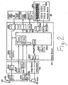
- a main board 50 (Fig. 2) including a control circuit for controlling the power, which is applied to the motor 32, in accordance with one of an output from the scale and that from the workpiece sensor the speed variation of which is larger than that of the other, an angle board 52, an analog board 54, and a display board 56 including a LED display 56A and a key switch 56B are mainly provided.
- the scale 40 is made of, for example, a photoelectric encoder fixed at an upper part of the spindle 10 and including a main scale 40A fixed at a lower end thereof to the holder 24 constituting a part of the parallel link mechanism 20, and a displacement detector 40B for detecting the vertical displacement of the main scale 40A.
- the angle board 52 is mounted with a circuit 52A which carries out an angle detecting operation on the basis of an output from the workpiece sensor 42.
- This workpiece sensor 42 is preferably a non-contact type sensor so as not to give influence upon a motion of the parallel link mechanism. Accordingly, it is preferable that this workpiece sensor 42 be made of a photocoupler.
- the photocoupler includes mainly a light-emitting element and a light receiving element, and is adapted to output two signals only, i.e. ON and OFF signals representative of the transmission of light and non-transmission of light through the light receiving element.
- an output signal from the light receiving element represents a light screening rate, so that an angle of the parallel link mechanism can be detected on the basis of this output signal.
- the analog board 54 is mounted with a driver 54A for the displacement detector 40B, an upper point detecting circuit 54B adapted to detect an upper limit position of the spindle 10 andplace restrictions on the movement of the spindle, and a motor current detecting circuit 54C for protecting the motor 32 from an overcurrent
- the main board 50 includes a receiver 50A adapted to receive an output from the driver 54A, a driver 50B for the motor 32, a microcomputer 50C including an A/D converter, a ROM, a RAM and a pulse width modulator (PWM) , its EEROM 50D, an I/O buffer 50E, an I/O driver 50F, a driver 50G for communication used to make communication by, for example, RS 232C, a LED driver 50H for driving the LED display 56A on the display board 56, and a key buffer 501 for driving a key switch 56B on the same display board 56.
- a receiver 50A adapted to receive an output from the driver 54A
- a driver 50B for the motor 32 includes a microcomputer 50C including an A/D converter, a ROM, a RAM and a pulse width modulator (PWM) , its EEROM 50D, an I/O buffer 50E, an I/O driver 50F, a driver 50G for communication used to make communication by, for example
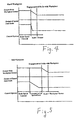
- a control operation in the microcomputer 50C is carried out in accordance with the algorithm shown in Fig. 3. Namely, the motor control operation is carried out as a control operation based on a PM speed command in accordance with a difference between a target carry-over position stored in a position memory (PM) and an actual position, and a control operation based on an output from the scale 40 and output data from the workpiece sensor 42 are switched from one to the other, and vice versa in accordance with the situation.
- PM position memory
- a speed control operation (called a scale'speed control operation) based on an output from a regular scale 40 is carried out until the engagement of the probe with the workpiece is detected owing to the variation of an output from the same sensor, and, when an output from the workpiece sensor 42 starts varying owing to the engagement of the same probe with the workpiece 8, a control operation is carried out (scale + sensor) in accordance with one of the scale 40 and workpiece sensor 42 the speed variation of which is larger than that of the other.
- the automatic holding of a measurement value and automatic retracting of the probe using an output from the workpiece sensor 42 are also possible as shown in Fig. 6. Namely, as shown in Fig. 6A, when the lowering of the probe 12 and the bringing of the same into contact with the workpiece 8 in Fig. 6B are detected by an output from the workpiece sensor 42, the measurement data or display value represented by an output signal from the displacement detector 40B of the scale 40 is taken in and held as a measurement value of the workpiece. This gives a judgement that the measurement operation is completed, and the probe 12 is retracted upward quickly by a predetermined quantity as shown in Fig. 6C. Thus, it becomes possible to conduct the automatic measurement of a workpiece 8 in which the deformation thereof is prevented to as great an extent as possible.
- the automatic measurement of maximum and minimum values of a plurality of workpieces using an output from the workpiece sensor 42 is also possible. Namely, as in the case of the measurement of maximum values illustrated in Fig. 7, the measurement of workpieces 8A, 8B, 8C is sequentially conducted in order that a peak value is altered only when the probe 12 contacts the workpiece 8 early during a downward movement of the probe. This enables the maximum values of the plural workpieces to be determined. Conversely, when a peak value is altered only when the probe contacts the workpiece late, minimum values can be determined.
- the measurement can also be.conducted by carrying out a control operation so that the probe is moved at a high speed up to a set height of PM1, and at a low speed from a set height of not greater than PM1 with a high position reproducibility (for example, ⁇ 1 ⁇ m with respect to a displayed value) to contact with the surface of the workpiece as shown in Fig. 8, by utilizing a value of a position memory (PM) made capable of storing the positions of, for example, up to three spindles.
- PM position memory
- an independent automatic measurement operation can be conducted with a displacement measuring apparatus without using a sequencer and a dedicated microcomputer.
- the vertical position of the probe 12 can be measured in a non-contact state and with a high accuracy.
- the kind of the scale is not limited to a photoelectric type.
- a linear type scale, which is other than the photoelectric type scale, such as an electrostatic capacity type scale, or a rotary scale can also be used.
- the displacement of the link member 20A can be detected in a non-contact state.
- the kind of the workpiece sensor is not limited to the photocoupler.
- a strain gauge and an electric microgauge can also be used.
- the kind of the motor 32 is not limited to a regular rotary motor either.
- Other kinds of motors such as a linear motor, a linear actuator, a piezoelectric motor, an ultrasonic motor and a rotary motor can also be used.
- the mechanism for retaining the probe 12 under a low measuring pressure is not limited either to the parallel link mechanism 20.
- a parallel leaf spring and a linear guide can also be used.
- the present invention it becomes possible to stabilize the low-speed feeding of a probe without additionally providing a new mechanism, such as a motor rotation detecting rotary encoder and a tachometer generator, andmeasure the size of a workpiece with low measuring power. Therefore, it becomes possible to omit a regulation operation during the assembling of the probe driving mechanism by abolishing the provision of, for example, a pulse width control knob, and thereby reduce the cost of manufacturing the driving mechanism and the dimensions thereof.
Landscapes
- Physics & Mathematics (AREA)
- General Physics & Mathematics (AREA)
- Length Measuring Devices With Unspecified Measuring Means (AREA)
- A Measuring Device Byusing Mechanical Method (AREA)
Applications Claiming Priority (2)
| Application Number | Priority Date | Filing Date | Title |
|---|---|---|---|
| JP2002311802A JP3850364B2 (ja) | 2002-10-25 | 2002-10-25 | 変位測定器の測定子駆動機構 |
| JP2002311802 | 2002-10-25 |
Publications (3)
| Publication Number | Publication Date |
|---|---|
| EP1413849A2 true EP1413849A2 (de) | 2004-04-28 |
| EP1413849A3 EP1413849A3 (de) | 2004-07-21 |
| EP1413849B1 EP1413849B1 (de) | 2014-05-07 |
Family
ID=32064389
Family Applications (1)
| Application Number | Title | Priority Date | Filing Date |
|---|---|---|---|
| EP03023865.3A Expired - Lifetime EP1413849B1 (de) | 2002-10-25 | 2003-10-21 | Tastsystem für Koordinatenmessgeräte |
Country Status (3)
| Country | Link |
|---|---|
| US (1) | US7024273B2 (de) |
| EP (1) | EP1413849B1 (de) |
| JP (1) | JP3850364B2 (de) |
Cited By (1)
| Publication number | Priority date | Publication date | Assignee | Title |
|---|---|---|---|---|
| GB2468766B (en) * | 2009-03-18 | 2013-03-27 | Helmut Fischer Gmbh Inst Fa R Elektronik Und Messtechnik | Measurement stand and method of its electrical control |
Families Citing this family (7)
| Publication number | Priority date | Publication date | Assignee | Title |
|---|---|---|---|---|
| DE102005034515B4 (de) | 2005-07-20 | 2019-06-19 | Immobiliengesellschaft Helmut Fischer Gmbh & Co. Kg | Messstativ zur Aufnahme einer Messvorrichtung |
| JP2007033417A (ja) * | 2005-07-21 | 2007-02-08 | Dyadic Systems Co Ltd | 量産用機械加工部品寸法検査装置 |
| JP2009216548A (ja) * | 2008-03-11 | 2009-09-24 | Mitsutoyo Corp | 測定装置 |
| KR101664203B1 (ko) * | 2009-05-12 | 2016-10-10 | 삼성전자 주식회사 | 태양전지를 구비하는 휴대 단말기의 충전 정보 제공 방법 및 장치 |
| DE112014002974T5 (de) | 2013-06-24 | 2016-06-09 | Dcg Systems, Inc. | Sondenbasierendes Datensammelsystem mit adaptiver Sonden-Untersuchung gesteuert durch lokale Eigenschaften der Probe |
| WO2015200724A1 (en) | 2014-06-25 | 2015-12-30 | Dcg Systems, Inc. | Apparatus and method for nanoprobing of electronic devices |
| JP2024018645A (ja) * | 2022-07-29 | 2024-02-08 | 株式会社ミツトヨ | 自動測定装置およびその制御方法 |
Citations (4)
| Publication number | Priority date | Publication date | Assignee | Title |
|---|---|---|---|---|
| JPS5810681B2 (ja) | 1974-03-09 | 1983-02-26 | カブシキガイシヤ ミツトヨセイサクシヨ | テイソクテイアツオアタエル ソクテイキ |
| JPS5919283B2 (ja) | 1977-11-14 | 1984-05-04 | 株式会社三豊製作所 | 寸法測定器 |
| JPH0778403B2 (ja) | 1989-02-22 | 1995-08-23 | 株式会社ミツトヨ | 寸法測定機 |
| US5713136A (en) | 1994-10-19 | 1998-02-03 | Nippon Thompson Co., Ltd. | Object measuring apparatus |
Family Cites Families (18)
| Publication number | Priority date | Publication date | Assignee | Title |
|---|---|---|---|---|
| US3633011A (en) * | 1968-08-29 | 1972-01-04 | Ibm | Method and apparatus for precisely contouring a workpiece imprecisely positioned on a supporting fixture |
| US4428055A (en) * | 1981-08-18 | 1984-01-24 | General Electric Company | Tool touch probe system and method of precision machining |
| US4882848A (en) * | 1987-07-30 | 1989-11-28 | Carl-Zeiss-Stiftung, Heidenheim/Brenz | Probe head for a coordinate-measuring instrument |
| DE3728578A1 (de) * | 1987-08-27 | 1989-03-09 | Zeiss Carl Fa | Tastsystem fuer koordinatenmessgeraete |
| DE4245012B4 (de) * | 1992-04-14 | 2004-09-23 | Carl Zeiss | Verfahren zur Messung von Formelementen auf einem Koordinatenmeßgerät |
| DE4420137A1 (de) * | 1994-06-09 | 1995-12-14 | Zeiss Messgeraetebau Gmbh | Meßgerät zur Überprüfung der Abmessungen von zylindrischen Werkstücken |
| JPH09189502A (ja) | 1996-01-08 | 1997-07-22 | Tokyo Seimitsu Co Ltd | 外形寸法測定装置 |
| US5822877A (en) * | 1996-06-20 | 1998-10-20 | Brown & Sharpe Manufacturing Company | Multi-probe system for dimensional metrology |
| JPH10307305A (ja) | 1997-03-07 | 1998-11-17 | Toshiba Corp | アレイ基板、液晶表示装置及びそれらの製造方法 |
| JP3474402B2 (ja) * | 1997-07-17 | 2003-12-08 | 株式会社ミツトヨ | 測定器 |
| JP3696432B2 (ja) * | 1999-04-13 | 2005-09-21 | 株式会社ミツトヨ | 一次元測定機 |
| TW478014B (en) | 1999-08-31 | 2002-03-01 | Semiconductor Energy Lab | Semiconductor device and method of manufacturing thereof |
| JP3799943B2 (ja) | 2000-03-17 | 2006-07-19 | セイコーエプソン株式会社 | 電気光学装置およびプロジェクタ |
| CN1267782C (zh) * | 2000-04-21 | 2006-08-02 | 精工爱普生株式会社 | 电光装置 |
| US6832877B2 (en) * | 2000-05-29 | 2004-12-21 | Kabushiki Kaisya Advance | Dental measuring and machining system |
| JP3731447B2 (ja) | 2000-06-15 | 2006-01-05 | セイコーエプソン株式会社 | 電気光学装置及びその製造方法 |
| JP2002131778A (ja) | 2000-10-23 | 2002-05-09 | Seiko Epson Corp | 電気光学装置用基板およびこれを備えた電気光学装置並びに電子機器 |
| JP3849434B2 (ja) | 2001-02-14 | 2006-11-22 | セイコーエプソン株式会社 | 電気光学装置及び投射型表示装置 |
-
2002
- 2002-10-25 JP JP2002311802A patent/JP3850364B2/ja not_active Expired - Fee Related
-
2003
- 2003-10-20 US US10/687,836 patent/US7024273B2/en not_active Expired - Lifetime
- 2003-10-21 EP EP03023865.3A patent/EP1413849B1/de not_active Expired - Lifetime
Patent Citations (4)
| Publication number | Priority date | Publication date | Assignee | Title |
|---|---|---|---|---|
| JPS5810681B2 (ja) | 1974-03-09 | 1983-02-26 | カブシキガイシヤ ミツトヨセイサクシヨ | テイソクテイアツオアタエル ソクテイキ |
| JPS5919283B2 (ja) | 1977-11-14 | 1984-05-04 | 株式会社三豊製作所 | 寸法測定器 |
| JPH0778403B2 (ja) | 1989-02-22 | 1995-08-23 | 株式会社ミツトヨ | 寸法測定機 |
| US5713136A (en) | 1994-10-19 | 1998-02-03 | Nippon Thompson Co., Ltd. | Object measuring apparatus |
Cited By (7)
| Publication number | Priority date | Publication date | Assignee | Title |
|---|---|---|---|---|
| GB2468766B (en) * | 2009-03-18 | 2013-03-27 | Helmut Fischer Gmbh Inst Fa R Elektronik Und Messtechnik | Measurement stand and method of its electrical control |
| GB2495868A (en) * | 2009-03-18 | 2013-04-24 | Helmut Fischer Gmbh Inst Fa R Elektronik Und Messtechnik | Measurement Stand and Method of its Electrical Control for Measuring Thin Layers |
| GB2495869A (en) * | 2009-03-18 | 2013-04-24 | Helmut Fischer Gmbh Inst Fa R Elektronik Und Messtechnik | A Method for Electrically Controlling a Measurement Stand with a Measurement Probe for Measuring the Thickness of Thin Layers |
| GB2496065A (en) * | 2009-03-18 | 2013-05-01 | Helmut Fischer Gmbh Inst Fauer Elektronik Und Messtechnik | Measurement Stand with means for Controlling Advancement of the Measurement Probe for Measuring the Thickness of Thin Layers |
| GB2495869B (en) * | 2009-03-18 | 2013-10-23 | Helmut Fischer Gmbh Inst Fur Elektronik Und Messtechnik | Measurement stand and method of its electrical control |
| GB2495868B (en) * | 2009-03-18 | 2013-10-23 | Helmut Fischer Gmbh Inst Fur Elektronik Und Messtechnik | Measurement stand and method of its electrical control |
| GB2496065B (en) * | 2009-03-18 | 2013-10-23 | Helmut Fischer Gmbh Inst Fur Elektronik Und Messtechnik | Measurement stand and method of its electrical control |
Also Published As
| Publication number | Publication date |
|---|---|
| US20040133300A1 (en) | 2004-07-08 |
| JP2004144682A (ja) | 2004-05-20 |
| EP1413849A3 (de) | 2004-07-21 |
| US7024273B2 (en) | 2006-04-04 |
| EP1413849B1 (de) | 2014-05-07 |
| JP3850364B2 (ja) | 2006-11-29 |
Similar Documents
| Publication | Publication Date | Title |
|---|---|---|
| US6209217B1 (en) | Surface-following type measuring machine | |
| EP0180610B1 (de) | Verbesserung bezüglich eines koordinaten positionierungsapparates | |
| EP1857775B1 (de) | Verfahren und Vorrichtung zur Steuerung des Messvorgangs eines Konturmessgeräts | |
| US5024003A (en) | Work-contacting probe system for a coordinate-measuring instrument | |
| US7039550B2 (en) | Surface scan measuring instrument, surface scan measuring method, surface scan measuring program and recording medium | |
| CA2321868C (en) | Method for controlling ic handler and control system using the same | |
| EP1413849B1 (de) | Tastsystem für Koordinatenmessgeräte | |
| US6194811B1 (en) | Drive apparatus | |
| EP1090699B1 (de) | Biegevorrichtung und seines Betriebsverfahren | |
| JP2012526268A (ja) | 表面形状の測定方法および装置 | |
| EP0242869B1 (de) | Numerische Steuerungseinrichtung | |
| US6484570B2 (en) | Impression forming mechanism and hardness testing apparatus | |
| JP4892736B2 (ja) | 卵殻強度測定方法および装置 | |
| JP4034906B2 (ja) | 表面性状測定機 | |
| US6510363B1 (en) | Surface texture measuring apparatus | |
| CN117470153A (zh) | 自动测量装置及其控制方法 | |
| KR100524346B1 (ko) | 마찰실험장치 | |
| JP2003202359A (ja) | 接触子の接触圧力制御装置 | |
| CN112229616B (zh) | 执行器测试系统及机构 | |
| JPH0926368A (ja) | 力学量センサ装置用自動較正装置 | |
| JPH05107048A (ja) | タツプ深さ測定装置 | |
| JP3852424B2 (ja) | 材料試験機用変位測定装置 | |
| JP2506657B2 (ja) | 電動プレス | |
| JP2533486B2 (ja) | 電動プレス | |
| EP4185854B1 (de) | Haptische rückmeldung zur konfiguration von materialtestsystemen |
Legal Events
| Date | Code | Title | Description |
|---|---|---|---|
| PUAI | Public reference made under article 153(3) epc to a published international application that has entered the european phase |
Free format text: ORIGINAL CODE: 0009012 |
|
| AK | Designated contracting states |
Kind code of ref document: A2 Designated state(s): AT BE BG CH CY CZ DE DK EE ES FI FR GB GR HU IE IT LI LU MC NL PT RO SE SI SK TR |
|
| AX | Request for extension of the european patent |
Extension state: AL LT LV MK |
|
| PUAL | Search report despatched |
Free format text: ORIGINAL CODE: 0009013 |
|
| AK | Designated contracting states |
Kind code of ref document: A3 Designated state(s): AT BE BG CH CY CZ DE DK EE ES FI FR GB GR HU IE IT LI LU MC NL PT RO SE SI SK TR |
|
| AX | Request for extension of the european patent |
Extension state: AL LT LV MK |
|
| RIC1 | Information provided on ipc code assigned before grant |
Ipc: 7G 01B 5/06 B Ipc: 7G 01B 3/00 B Ipc: 7G 01B 7/012 A |
|
| 17P | Request for examination filed |
Effective date: 20040831 |
|
| AKX | Designation fees paid |
Designated state(s): DE FR GB IT |
|
| 17Q | First examination report despatched |
Effective date: 20050513 |
|
| REG | Reference to a national code |
Ref country code: DE Ref legal event code: R079 Ref document number: 60346117 Country of ref document: DE Free format text: PREVIOUS MAIN CLASS: G01B0007012000 Ipc: G01B0007000000 |
|
| RIC1 | Information provided on ipc code assigned before grant |
Ipc: G01B 7/00 20060101AFI20130828BHEP Ipc: G01B 7/012 20060101ALI20130828BHEP |
|
| GRAP | Despatch of communication of intention to grant a patent |
Free format text: ORIGINAL CODE: EPIDOSNIGR1 |
|
| INTG | Intention to grant announced |
Effective date: 20140103 |
|
| GRAS | Grant fee paid |
Free format text: ORIGINAL CODE: EPIDOSNIGR3 |
|
| GRAA | (expected) grant |
Free format text: ORIGINAL CODE: 0009210 |
|
| AK | Designated contracting states |
Kind code of ref document: B1 Designated state(s): DE FR GB IT |
|
| REG | Reference to a national code |
Ref country code: GB Ref legal event code: FG4D |
|
| REG | Reference to a national code |
Ref country code: DE Ref legal event code: R096 Ref document number: 60346117 Country of ref document: DE Effective date: 20140618 |
|
| REG | Reference to a national code |
Ref country code: DE Ref legal event code: R097 Ref document number: 60346117 Country of ref document: DE |
|
| PLBE | No opposition filed within time limit |
Free format text: ORIGINAL CODE: 0009261 |
|
| STAA | Information on the status of an ep patent application or granted ep patent |
Free format text: STATUS: NO OPPOSITION FILED WITHIN TIME LIMIT |
|
| 26N | No opposition filed |
Effective date: 20150210 |
|
| REG | Reference to a national code |
Ref country code: DE Ref legal event code: R097 Ref document number: 60346117 Country of ref document: DE Effective date: 20150210 |
|
| REG | Reference to a national code |
Ref country code: FR Ref legal event code: PLFP Year of fee payment: 13 |
|
| REG | Reference to a national code |
Ref country code: FR Ref legal event code: PLFP Year of fee payment: 14 |
|
| REG | Reference to a national code |
Ref country code: FR Ref legal event code: PLFP Year of fee payment: 15 |
|
| REG | Reference to a national code |
Ref country code: FR Ref legal event code: PLFP Year of fee payment: 16 |
|
| PGFP | Annual fee paid to national office [announced via postgrant information from national office to epo] |
Ref country code: FR Payment date: 20221028 Year of fee payment: 20 |
|
| PGFP | Annual fee paid to national office [announced via postgrant information from national office to epo] |
Ref country code: IT Payment date: 20221026 Year of fee payment: 20 Ref country code: GB Payment date: 20221019 Year of fee payment: 20 Ref country code: DE Payment date: 20220620 Year of fee payment: 20 |
|
| REG | Reference to a national code |
Ref country code: DE Ref legal event code: R071 Ref document number: 60346117 Country of ref document: DE |
|
| REG | Reference to a national code |
Ref country code: GB Ref legal event code: PE20 Expiry date: 20231020 |
|
| PG25 | Lapsed in a contracting state [announced via postgrant information from national office to epo] |
Ref country code: GB Free format text: LAPSE BECAUSE OF EXPIRATION OF PROTECTION Effective date: 20231020 |
|
| PG25 | Lapsed in a contracting state [announced via postgrant information from national office to epo] |
Ref country code: GB Free format text: LAPSE BECAUSE OF EXPIRATION OF PROTECTION Effective date: 20231020 |