EP1857775B1 - Verfahren und Vorrichtung zur Steuerung des Messvorgangs eines Konturmessgeräts - Google Patents
Verfahren und Vorrichtung zur Steuerung des Messvorgangs eines Konturmessgeräts Download PDFInfo
- Publication number
- EP1857775B1 EP1857775B1 EP07009724A EP07009724A EP1857775B1 EP 1857775 B1 EP1857775 B1 EP 1857775B1 EP 07009724 A EP07009724 A EP 07009724A EP 07009724 A EP07009724 A EP 07009724A EP 1857775 B1 EP1857775 B1 EP 1857775B1
- Authority
- EP
- European Patent Office
- Prior art keywords
- force
- force sensor
- workpiece
- control loop
- probe
- Prior art date
- Legal status (The legal status is an assumption and is not a legal conclusion. Google has not performed a legal analysis and makes no representation as to the accuracy of the status listed.)
- Active
Links
Images





Classifications
-
- G—PHYSICS
- G01—MEASURING; TESTING
- G01B—MEASURING LENGTH, THICKNESS OR SIMILAR LINEAR DIMENSIONS; MEASURING ANGLES; MEASURING AREAS; MEASURING IRREGULARITIES OF SURFACES OR CONTOURS
- G01B5/00—Measuring arrangements characterised by the use of mechanical techniques
- G01B5/004—Measuring arrangements characterised by the use of mechanical techniques for measuring coordinates of points
- G01B5/008—Measuring arrangements characterised by the use of mechanical techniques for measuring coordinates of points using coordinate measuring machines
- G01B5/012—Contact-making feeler heads therefor
-
- G—PHYSICS
- G01—MEASURING; TESTING
- G01B—MEASURING LENGTH, THICKNESS OR SIMILAR LINEAR DIMENSIONS; MEASURING ANGLES; MEASURING AREAS; MEASURING IRREGULARITIES OF SURFACES OR CONTOURS
- G01B21/00—Measuring arrangements or details thereof, where the measuring technique is not covered by the other groups of this subclass, unspecified or not relevant
- G01B21/02—Measuring arrangements or details thereof, where the measuring technique is not covered by the other groups of this subclass, unspecified or not relevant for measuring length, width, or thickness
- G01B21/04—Measuring arrangements or details thereof, where the measuring technique is not covered by the other groups of this subclass, unspecified or not relevant for measuring length, width, or thickness by measuring coordinates of points
-
- G—PHYSICS
- G01—MEASURING; TESTING
- G01B—MEASURING LENGTH, THICKNESS OR SIMILAR LINEAR DIMENSIONS; MEASURING ANGLES; MEASURING AREAS; MEASURING IRREGULARITIES OF SURFACES OR CONTOURS
- G01B3/00—Measuring instruments characterised by the use of mechanical techniques
- G01B3/002—Details
- G01B3/008—Arrangements for controlling the measuring force
Definitions
- a relative moving amount of the X-beam 154 and the X-slide 161 is measured by a displacement detector (not shown).
- Figs. 4A to 4D are each a schematic diagram showing a positional relationship of the force sensor and the workpiece in the measurement.
- Fig. 4A shows an initial state
- Fig. 4B shows a state in which the force sensor is moved by the X-direction driver, the Y-direction driver and the Z-direction driver from the state shown in Fig. 4A to the probe-controllable position
- Fig. 4C shows a state in which the force sensor is moved by the actuator from the state shown in Fig. 4B to the close position under the position control
- Fig. 4D shows a state in which the force sensor is moved by the actuator from the state shown in Fig. 4C and brought into contact with the workpiece under the force control.
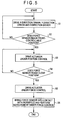
- Fig. 5 is a flowchart showing the measurement using the coordinate measuring instrument.
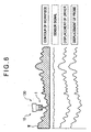
- Fig. 6 is a conceptual diagram showing how the workpiece is measured.
- Step S4 when it is judged that the force sensor 1 reaches the close position in Step S4, the contact controller 235 enables the force control loop RF to drive the actuator 133 under the force control (Step S5). Then, as shown in Fig. 4D , the force sensor 1 is brought into contact with the workpiece W while keeping the force control, and the measurement is performed under the force control (Step S6).
Landscapes
- Physics & Mathematics (AREA)
- General Physics & Mathematics (AREA)
- A Measuring Device Byusing Mechanical Method (AREA)
Claims (4)
- Messungs-Steuervorrichtung (233), die umfasst:eine Sonde (130), die einen Kraftsensor (1) enthält, der eine Messkraft erfasst, die erzeugt wird, wenn die-Sonde (130) mit einem Werkstück (W) in Kontakt kommt, und die Messkraft als ein Krafterfassungssignal ausgibt;eine Kraftsensor-Bewegungseinheit (133), die den Kraftsensor (1) relativ zu dem Werkstück (W) bewegt;eine Positionserfassungseinrichtung (135), die eine Messpositionsinformation des Kraftsensors (1) erfasst und ausgibt;einen Kraft-Regelkreis (RF), der das Krafterfassungssignal von dem Kraftsensor (1) als ein Kraft-Rückkopplungssignal mit einem Kraft-Sollwert vergleicht und die Kraftsensor-Bewegungseinheit (133) so antreibt, dass das Kraft-Rückkopplungssignal dem Kraft-Sollwert gleich wird;einen Positions-Regelkreis (RP), der die Messpositionsinformation von der Positionserfassungseinrichtung (135) als ein Positions-Rückkopplungssignal mit einem Positions-Sollwert vergleicht und die Kraftsensor-Bewegungseinheit (133) so antreibt, dass das Positions-Rückkopplungssignal dem Positions-Sollwert gleich wird;eine Regelkreis-Umschalteinrichtung (227), die den Kraft-Regelkreis (RF) oder den Positions-Regelkreis (RP) aktiviert;eine Annäherungs-Steuereinrichtung (234), die die Regelkreis-Umschalteinrichtung (227) so steuert, dass sie den Positions-Regelkreis (RP) aktiviert, und die Kraftsensor-Bewegungseinheit (133) antreibt, um den Kraftsensor (1) an einer nahen Position zu positionieren, die nahe an dem Werkstück (W) liegt, so dass das Positions-Rückkopplungssignal dem Positions-Sollwert gleich wird; undeine Kontakt-Steuereinrichtung (235), die, wenn erkannt wird, dass der Kraftsensor (1) von der Annäherungs-Steuereinrichtung (234) gesteuert an die Position nahe an dem Werkstück (W) gebracht wird, die Regelkreis-Umschalteinrichtung (227) so steuert,dass der Kraft-Regelkreis (RF) aktiviert wird, und die Kraftsensor-Bewegungseinheit (133) so antreibt, dass sie den Kraftsensor (1) derart in Kontakt mit dem Werkstück (W) bringt, dass das Kraft-Rückkoppelungssignal dem Kraft-Sollwert gleich wird.
- Messungs-Steuervorrichtung (233) nach Anspruch 1, wobei der Kraftsensor (1) einen Taststift (3) mit einem Kontaktabschnitt (6) an seinem vorderen Ende, ein Schwingelement (4), das den Taststift (3) in Schwingung versetzt, und ein Erfassungselement (5) enthält, das einen Schwingungszustand des Taststiftes (3) erfasst und den Schwingungszustand als ein Erfassungssignal ausgibt.
- Konturmessinstrument (10), das umfasst:die Messungs-Steuervorrichtung (233) nach Anspruch 1 oder 2;einen Sondenhalter (172), der die Sonde (130) der Messungs-Steuervorrichtung (233) hält;eine Sonden-Relativbewegungseinheit (152R, 152L, 161), die den Sondenhalter (172) und das Werkstück (W) relativ zueinander bewegt;eine Sondenpositions-Steuereinrichtung (210), die die Sonden-Relativbewegungseinheit (152R, 152L, 161) so steuert, dass sie den Kraftsensor (1) der Sonde (130) unddas Werkstück (W) so positioniert, das der Kraftsensor eine steuerbare Position der Sonde relativ zu dem Werkstück (W) erreicht, wobeiwenn erkannt wird, dass sich der Kraftsensor (1) an der steuerbaren Position der Sonde befindet, die Annäherungs-Steuereinrichtung (234) den Kraftsensor (1) und das Werkstück (W) nahe aneinander positioniert.
- Messungs-Steuerverfahren, bei dem eine Messungs-Steuervorrichtung (233) verwendet wird, die enthält:eine Sonde (130), die einen Kraftsensor (1) enthält, der eine Messkraft erfasst, die erzeugt wird, wenn die Sonde (130) mit einem Werkstück (W) in Kontakt kommt, und die Messkraft als ein Krafterfassungssignal ausgibt;eine Kraftsensor-Bewegungseinheit (133), die den Kraftsensor (1) relativ zu dem Werkstück (W) bewegt;eine Positionserfassungseinrichtung (135), die eine Messungspositionsinformation des Kraftsensors (1) erfasst und ausgibt;einen Kraft-Regelkreis (RF), der das Krafterfassungssignal von dem Kraftsensor (1) als ein Kraft-Rückkoppelungssignal mit einem Kraft-Sollwert vergleicht und die Kraftsensor-Bewegungseinheit (133) so antreibt, dass das Kraft-Rückkoppelungssignal dem Kraft-Sollwert gleich wird;einen Positions-Regelkreis (RP), der die Messpositionsinformation von der Positionserfassungseinrichtung (135) als ein Positions-Rückkoppelungssignal mit einem Positions-Sollwert vergleicht und die Kraftsensor-Bewegungseinheit (133) so antreibt, dass das Positionsrückkopplungssignal dem Positions-Sollwert gleich wird; undeine Regelkreis-Umschalteinrichtung (227), die den Kraft-Regelkreis (RF) oder den Positions-Regelkreis (RP) aktiviert, wobei das Verfahren umfasst:Steuern der Regelschleifen-Umschalteinrichtung (277), so dass sie die Positions-Regelschleife (RP) aktiviert und die Kraftsensor-Bewegungseinheit (133) antreibt, um den Kraftsensor (1) an eine Position nahe an dem Werkstück (W) zu bewegen, so dass das Positions-Rückkopplungssignal dem Positions-Sollwert gleich wird; undwenn erkannt wird, dass der Kraftsensor (1) an die Position nahe an dem Werkstück (W) gebracht wird, Steuern der Regelkreis-Umschalteinrichtung (227) so, dass sie den Kraft-Regelkreis (RF) aktiviert, und Antreiben der Kraftsensor-Bewegungseinheit (133), so dass sie den Kraftsensor (1) derart in Kontakt mit dem Werkstück (W) bringt, dass das Kraft-Rückkopplungssignal dem Kraft-Sollwert gleich wird.
Applications Claiming Priority (1)
| Application Number | Priority Date | Filing Date | Title |
|---|---|---|---|
| JP2006136628A JP2007309684A (ja) | 2006-05-16 | 2006-05-16 | 測定制御装置、表面性状測定装置、および、測定制御方法 |
Publications (2)
| Publication Number | Publication Date |
|---|---|
| EP1857775A1 EP1857775A1 (de) | 2007-11-21 |
| EP1857775B1 true EP1857775B1 (de) | 2008-12-10 |
Family
ID=38291004
Family Applications (1)
| Application Number | Title | Priority Date | Filing Date |
|---|---|---|---|
| EP07009724A Active EP1857775B1 (de) | 2006-05-16 | 2007-05-15 | Verfahren und Vorrichtung zur Steuerung des Messvorgangs eines Konturmessgeräts |
Country Status (4)
| Country | Link |
|---|---|
| US (1) | US7784333B2 (de) |
| EP (1) | EP1857775B1 (de) |
| JP (1) | JP2007309684A (de) |
| DE (1) | DE602007000340D1 (de) |
Families Citing this family (27)
| Publication number | Priority date | Publication date | Assignee | Title |
|---|---|---|---|---|
| JP4568621B2 (ja) * | 2005-02-28 | 2010-10-27 | 株式会社ミツトヨ | 表面性状測定機の真直度補正方法および表面性状測定機 |
| DE102006023292B4 (de) * | 2006-05-18 | 2008-02-21 | Carl Mahr Holding Gmbh | Messvorrichtung für schnelle Messungen |
| JP5199582B2 (ja) * | 2007-02-14 | 2013-05-15 | 株式会社ミツトヨ | 接触式プローブの倣い制御方法及び接触式測定機 |
| JP5022930B2 (ja) * | 2008-01-31 | 2012-09-12 | 株式会社ミツトヨ | 接触式振動計およびこれを備えた表面性状測定装置 |
| JP5265976B2 (ja) | 2008-07-01 | 2013-08-14 | 株式会社ミツトヨ | 測定機 |
| JP5438995B2 (ja) * | 2009-03-10 | 2014-03-12 | 株式会社ミツトヨ | 形状測定機および倣いプローブ装置 |
| CN101520321B (zh) * | 2009-03-30 | 2011-04-06 | 哈尔滨工业大学 | 精度检测设备 |
| JP5371532B2 (ja) * | 2009-04-23 | 2013-12-18 | 株式会社ミツトヨ | 三次元測定機 |
| DE102009020294A1 (de) * | 2009-05-07 | 2010-11-18 | Mahr Gmbh | Verfahren und Vorrichtung zur Messung eines Oberflächenprofils |
| JP5439157B2 (ja) * | 2009-12-22 | 2014-03-12 | 三菱重工業株式会社 | 歯車測定方法 |
| JP5557620B2 (ja) * | 2010-06-29 | 2014-07-23 | 株式会社ミツトヨ | 形状測定装置 |
| JP5843531B2 (ja) * | 2010-09-27 | 2016-01-13 | 株式会社ミツトヨ | 座標測定用ヘッドユニット及び座標測定機 |
| FR2972526B1 (fr) * | 2011-03-10 | 2016-05-20 | Commissariat Energie Atomique | Dispositif de mesure de l'etat de surface d'une surface |
| EP2498076A1 (de) | 2011-03-11 | 2012-09-12 | Hexagon Technology Center GmbH | Verschleissüberwachung einer Schaltung in einer Stromstation |
| EP2505956A1 (de) | 2011-03-29 | 2012-10-03 | Hexagon Technology Center GmbH | Koordinatenmessmaschine |
| JP6093506B2 (ja) * | 2012-03-19 | 2017-03-08 | 株式会社ミツトヨ | 表面性状測定機および表面性状測定方法 |
| CN103455045A (zh) * | 2012-05-30 | 2013-12-18 | 鸿富锦精密工业(深圳)有限公司 | 接触式运动控制系统及方法 |
| JP6212148B2 (ja) * | 2016-02-26 | 2017-10-11 | 株式会社ミツトヨ | 測定プローブ |
| JP6216400B2 (ja) * | 2016-02-26 | 2017-10-18 | 株式会社ミツトヨ | 測定プローブ |
| DK3367053T3 (da) * | 2017-02-27 | 2021-05-10 | Kulzer & Co Gmbh | 3d-scanner med gyroskopsensor |
| JP6946057B2 (ja) | 2017-05-30 | 2021-10-06 | キヤノン株式会社 | ロボットハンド、ロボットハンドの制御方法、ロボット装置 |
| DE102017113709B4 (de) * | 2017-06-21 | 2019-01-24 | Carl Mahr Holding Gmbh | Messarmaufnahmeeinrichtung eines Messsystems |
| DE102018112805A1 (de) * | 2018-05-29 | 2019-12-05 | Klingelnberg Gmbh | Verfahren zur Analyse von Oberflächenwelligkeiten |
| DE102020108182A1 (de) * | 2019-05-07 | 2020-11-12 | Jenoptik Industrial Metrology Germany Gmbh | Oberflächenmessgerät |
| TWI731650B (zh) * | 2020-04-15 | 2021-06-21 | 宏碁股份有限公司 | 觸控筆、觸控電子裝置與觸控系統 |
| US11644375B2 (en) * | 2020-09-03 | 2023-05-09 | GM Global Technology Operations LLC | Insertion force measurement system |
| CN121199647A (zh) * | 2025-11-28 | 2025-12-26 | 上海交大智邦科技有限公司 | 基于力感知的孔位测量装置的控制方法及系统 |
Family Cites Families (16)
| Publication number | Priority date | Publication date | Assignee | Title |
|---|---|---|---|---|
| JPS62119610A (ja) * | 1985-11-20 | 1987-05-30 | Fujitsu Ltd | 触覚を有するア−ムの駆動制御装置 |
| DE4013742C2 (de) * | 1990-04-28 | 1994-06-30 | Focus Mestechnik Gmbh & Co Kg | Abtastkopf für eine Maschine zum Ausmessen der Mikrooberflächenkontur von Werkstücken |
| JP3272952B2 (ja) * | 1996-07-02 | 2002-04-08 | キヤノン株式会社 | 3次元形状測定装置 |
| JP3533318B2 (ja) * | 1997-10-01 | 2004-05-31 | 株式会社リコー | 位置決め制御装置 |
| DE19809690A1 (de) * | 1998-03-06 | 1999-09-09 | Zeiss Carl Fa | Koordinatenmeßgerät mit Benutzerführung |
| JP3097847B2 (ja) * | 1998-06-19 | 2000-10-10 | 日本電気株式会社 | 二段アクチュエータによるヘッド位置決め装置 |
| JP2000089829A (ja) * | 1998-09-14 | 2000-03-31 | Yaskawa Electric Corp | 位置制御方法および装置 |
| JP2000155019A (ja) * | 1998-11-18 | 2000-06-06 | Ricoh Co Ltd | 形状測定装置 |
| JP3401444B2 (ja) * | 1998-12-15 | 2003-04-28 | 株式会社ミツトヨ | 微細形状測定装置 |
| JP2001166831A (ja) * | 1999-12-09 | 2001-06-22 | Matsushita Electric Ind Co Ltd | 位置制御装置 |
| JP2001264050A (ja) * | 2000-03-14 | 2001-09-26 | Mitsutoyo Corp | 微細形状測定装置 |
| JP2003097938A (ja) * | 2001-09-21 | 2003-04-03 | Ricoh Co Ltd | 制御装置、制御方法、形状測定装置及びロボット |
| JP2004061322A (ja) * | 2002-07-29 | 2004-02-26 | Mitsutoyo Corp | 表面形状測定装置 |
| JP2004077307A (ja) * | 2002-08-20 | 2004-03-11 | Canon Inc | 制御方式の切り替え方法 |
| JP4330388B2 (ja) * | 2003-07-28 | 2009-09-16 | 株式会社ミツトヨ | 倣いプローブ |
| JP4909548B2 (ja) | 2005-09-01 | 2012-04-04 | 株式会社ミツトヨ | 表面形状測定装置 |
-
2006
- 2006-05-16 JP JP2006136628A patent/JP2007309684A/ja active Pending
-
2007
- 2007-05-14 US US11/798,452 patent/US7784333B2/en active Active
- 2007-05-15 EP EP07009724A patent/EP1857775B1/de active Active
- 2007-05-15 DE DE602007000340T patent/DE602007000340D1/de active Active
Also Published As
| Publication number | Publication date |
|---|---|
| JP2007309684A (ja) | 2007-11-29 |
| US20070266781A1 (en) | 2007-11-22 |
| DE602007000340D1 (de) | 2009-01-22 |
| EP1857775A1 (de) | 2007-11-21 |
| US7784333B2 (en) | 2010-08-31 |
Similar Documents
| Publication | Publication Date | Title |
|---|---|---|
| EP1857775B1 (de) | Verfahren und Vorrichtung zur Steuerung des Messvorgangs eines Konturmessgeräts | |
| JP4478248B2 (ja) | 測定エラー低減方法および該方法を用いる測定機械 | |
| US7685733B2 (en) | Micro force measurement device, micro force measurement method, and micro surface shape measurement probe | |
| JP5639934B2 (ja) | 表面性状測定機 | |
| EP1503174B1 (de) | Beschleunigungskompensierte Abtastungssonde | |
| US7318285B2 (en) | Surface profile measuring instrument | |
| JPH0557606A (ja) | 研磨方法および研磨装置 | |
| EP2141445B1 (de) | Messinstrument | |
| Fan et al. | A scanning contact probe for a micro-coordinate measuring machine (CMM) | |
| US5450746A (en) | Constant force stylus profiling apparatus and method | |
| JPH1019504A (ja) | 3次元形状測定装置 | |
| TWI501058B (zh) | 用以改善站台移動時間之方法、系統及設備 | |
| JP5091702B2 (ja) | プローブの真直度測定方法 | |
| JP2025036506A (ja) | 形状測定装置 | |
| US5550483A (en) | High speed test probe positioning system | |
| JP5438995B2 (ja) | 形状測定機および倣いプローブ装置 | |
| JP7256389B2 (ja) | 形状測定装置 | |
| JP3602434B2 (ja) | 高精度移動機構 | |
| JP6198393B2 (ja) | 接触式三次元形状測定装置及びプローブ制御方法 | |
| JP2003202359A (ja) | 接触子の接触圧力制御装置 | |
| CN114563981A (zh) | 一种微小间隙非接触测量调控装置及方法 | |
| JP3523510B2 (ja) | 直線案内装置 | |
| JP2002090134A (ja) | 微細形状測定装置 | |
| JP2007057308A (ja) | 接触式プローブ | |
| JPH07136801A (ja) | バイト移動式切削装置 |
Legal Events
| Date | Code | Title | Description |
|---|---|---|---|
| PUAI | Public reference made under article 153(3) epc to a published international application that has entered the european phase |
Free format text: ORIGINAL CODE: 0009012 |
|
| AK | Designated contracting states |
Kind code of ref document: A1 Designated state(s): AT BE BG CH CY CZ DE DK EE ES FI FR GB GR HU IE IS IT LI LT LU LV MC MT NL PL PT RO SE SI SK TR |
|
| AX | Request for extension of the european patent |
Extension state: AL BA HR MK YU |
|
| 17P | Request for examination filed |
Effective date: 20080304 |
|
| RIC1 | Information provided on ipc code assigned before grant |
Ipc: G01B 7/012 20060101ALI20080410BHEP Ipc: G01B 21/04 20060101AFI20080410BHEP |
|
| RTI1 | Title (correction) |
Free format text: METHOD AND DEVICE FOR CONTROLLING THE MEASURING OPERATION OF A CONTOUR MEASURING INSTRUMENT |
|
| GRAP | Despatch of communication of intention to grant a patent |
Free format text: ORIGINAL CODE: EPIDOSNIGR1 |
|
| AKX | Designation fees paid |
Designated state(s): DE FR GB |
|
| GRAS | Grant fee paid |
Free format text: ORIGINAL CODE: EPIDOSNIGR3 |
|
| GRAA | (expected) grant |
Free format text: ORIGINAL CODE: 0009210 |
|
| AK | Designated contracting states |
Kind code of ref document: B1 Designated state(s): DE FR GB |
|
| REG | Reference to a national code |
Ref country code: GB Ref legal event code: FG4D |
|
| REF | Corresponds to: |
Ref document number: 602007000340 Country of ref document: DE Date of ref document: 20090122 Kind code of ref document: P |
|
| PLBE | No opposition filed within time limit |
Free format text: ORIGINAL CODE: 0009261 |
|
| STAA | Information on the status of an ep patent application or granted ep patent |
Free format text: STATUS: NO OPPOSITION FILED WITHIN TIME LIMIT |
|
| 26N | No opposition filed |
Effective date: 20090911 |
|
| REG | Reference to a national code |
Ref country code: FR Ref legal event code: PLFP Year of fee payment: 10 |
|
| REG | Reference to a national code |
Ref country code: FR Ref legal event code: PLFP Year of fee payment: 11 |
|
| REG | Reference to a national code |
Ref country code: FR Ref legal event code: PLFP Year of fee payment: 12 |
|
| PGFP | Annual fee paid to national office [announced via postgrant information from national office to epo] |
Ref country code: FR Payment date: 20200522 Year of fee payment: 14 |
|
| PGFP | Annual fee paid to national office [announced via postgrant information from national office to epo] |
Ref country code: GB Payment date: 20200527 Year of fee payment: 14 |
|
| GBPC | Gb: european patent ceased through non-payment of renewal fee |
Effective date: 20210515 |
|
| PG25 | Lapsed in a contracting state [announced via postgrant information from national office to epo] |
Ref country code: GB Free format text: LAPSE BECAUSE OF NON-PAYMENT OF DUE FEES Effective date: 20210515 |
|
| PG25 | Lapsed in a contracting state [announced via postgrant information from national office to epo] |
Ref country code: FR Free format text: LAPSE BECAUSE OF NON-PAYMENT OF DUE FEES Effective date: 20210531 |
|
| PGFP | Annual fee paid to national office [announced via postgrant information from national office to epo] |
Ref country code: DE Payment date: 20250521 Year of fee payment: 19 |