EP1413758B1 - Spiralverdichter mit Ölabscheider - Google Patents
Spiralverdichter mit Ölabscheider Download PDFInfo
- Publication number
- EP1413758B1 EP1413758B1 EP03022491A EP03022491A EP1413758B1 EP 1413758 B1 EP1413758 B1 EP 1413758B1 EP 03022491 A EP03022491 A EP 03022491A EP 03022491 A EP03022491 A EP 03022491A EP 1413758 B1 EP1413758 B1 EP 1413758B1
- Authority
- EP
- European Patent Office
- Prior art keywords
- compressor
- oil
- refrigerant
- oil separator
- motor housing
- Prior art date
- Legal status (The legal status is an assumption and is not a legal conclusion. Google has not performed a legal analysis and makes no representation as to the accuracy of the status listed.)
- Expired - Lifetime
Links
Images



Classifications
-
- F—MECHANICAL ENGINEERING; LIGHTING; HEATING; WEAPONS; BLASTING
- F04—POSITIVE - DISPLACEMENT MACHINES FOR LIQUIDS; PUMPS FOR LIQUIDS OR ELASTIC FLUIDS
- F04C—ROTARY-PISTON, OR OSCILLATING-PISTON, POSITIVE-DISPLACEMENT MACHINES FOR LIQUIDS; ROTARY-PISTON, OR OSCILLATING-PISTON, POSITIVE-DISPLACEMENT PUMPS
- F04C29/00—Component parts, details or accessories of pumps or pumping installations, not provided for in groups F04C18/00 - F04C28/00
- F04C29/12—Arrangements for admission or discharge of the working fluid, e.g. constructional features of the inlet or outlet
- F04C29/124—Arrangements for admission or discharge of the working fluid, e.g. constructional features of the inlet or outlet with inlet and outlet valves specially adapted for rotary or oscillating piston pumps
- F04C29/126—Arrangements for admission or discharge of the working fluid, e.g. constructional features of the inlet or outlet with inlet and outlet valves specially adapted for rotary or oscillating piston pumps of the non-return type
-
- F—MECHANICAL ENGINEERING; LIGHTING; HEATING; WEAPONS; BLASTING
- F04—POSITIVE - DISPLACEMENT MACHINES FOR LIQUIDS; PUMPS FOR LIQUIDS OR ELASTIC FLUIDS
- F04C—ROTARY-PISTON, OR OSCILLATING-PISTON, POSITIVE-DISPLACEMENT MACHINES FOR LIQUIDS; ROTARY-PISTON, OR OSCILLATING-PISTON, POSITIVE-DISPLACEMENT PUMPS
- F04C18/00—Rotary-piston pumps specially adapted for elastic fluids
- F04C18/02—Rotary-piston pumps specially adapted for elastic fluids of arcuate-engagement type, i.e. with circular translatory movement of co-operating members, each member having the same number of teeth or tooth-equivalents
- F04C18/0207—Rotary-piston pumps specially adapted for elastic fluids of arcuate-engagement type, i.e. with circular translatory movement of co-operating members, each member having the same number of teeth or tooth-equivalents both members having co-operating elements in spiral form
- F04C18/0215—Rotary-piston pumps specially adapted for elastic fluids of arcuate-engagement type, i.e. with circular translatory movement of co-operating members, each member having the same number of teeth or tooth-equivalents both members having co-operating elements in spiral form where only one member is moving
-
- F—MECHANICAL ENGINEERING; LIGHTING; HEATING; WEAPONS; BLASTING
- F04—POSITIVE - DISPLACEMENT MACHINES FOR LIQUIDS; PUMPS FOR LIQUIDS OR ELASTIC FLUIDS
- F04C—ROTARY-PISTON, OR OSCILLATING-PISTON, POSITIVE-DISPLACEMENT MACHINES FOR LIQUIDS; ROTARY-PISTON, OR OSCILLATING-PISTON, POSITIVE-DISPLACEMENT PUMPS
- F04C23/00—Combinations of two or more pumps, each being of rotary-piston or oscillating-piston type, specially adapted for elastic fluids; Pumping installations specially adapted for elastic fluids; Multi-stage pumps specially adapted for elastic fluids
- F04C23/008—Hermetic pumps
-
- F—MECHANICAL ENGINEERING; LIGHTING; HEATING; WEAPONS; BLASTING
- F04—POSITIVE - DISPLACEMENT MACHINES FOR LIQUIDS; PUMPS FOR LIQUIDS OR ELASTIC FLUIDS
- F04C—ROTARY-PISTON, OR OSCILLATING-PISTON, POSITIVE-DISPLACEMENT MACHINES FOR LIQUIDS; ROTARY-PISTON, OR OSCILLATING-PISTON, POSITIVE-DISPLACEMENT PUMPS
- F04C29/00—Component parts, details or accessories of pumps or pumping installations, not provided for in groups F04C18/00 - F04C28/00
- F04C29/02—Lubrication; Lubricant separation
- F04C29/025—Lubrication; Lubricant separation using a lubricant pump
-
- Y—GENERAL TAGGING OF NEW TECHNOLOGICAL DEVELOPMENTS; GENERAL TAGGING OF CROSS-SECTIONAL TECHNOLOGIES SPANNING OVER SEVERAL SECTIONS OF THE IPC; TECHNICAL SUBJECTS COVERED BY FORMER USPC CROSS-REFERENCE ART COLLECTIONS [XRACs] AND DIGESTS
- Y10—TECHNICAL SUBJECTS COVERED BY FORMER USPC
- Y10S—TECHNICAL SUBJECTS COVERED BY FORMER USPC CROSS-REFERENCE ART COLLECTIONS [XRACs] AND DIGESTS
- Y10S418/00—Rotary expansible chamber devices
- Y10S418/01—Non-working fluid separation
Definitions
- the invention relates to a compressor for refrigerants, comprising an outer casing, a arranged in the outer casing scroll compressor with a first, fixed in the outer housing compressor body and a second compressor body movable relative to the first compressor body, each one floor and above the respective floor have uplifting first and second spiral ribs, which interlock, that for compressing the refrigerant, the second compressor body opposite the first compressor body on an orbital track about a central axis is movable, a drive unit for the second compressor body with an eccentric drive, a drive shaft, a in a motor housing arranged and flowed around by the sucked refrigerant drive motor and a bearing unit for the drive shaft, which has a first, with the Enclosed outer housing comprises bearing body.
- the drive motor sits in an inner shell, which via a support element an outer casing is supported to the generation of noise and To suppress vibrations.
- the invention is therefore based on the object, a compressor of generic type to improve that of the scroll compressor sucked refrigerant is as much as possible free of lubricating oil.
- the gap could still be unilaterally the drive unit be arranged. It is particularly useful in terms of possible large available space when the gap the Surrounds drive unit and thus runs around the drive unit on all sides, for an optimal use of free space in the outer housing too receive.
- the gap is not only for the arrangement of the oil separator but preferably used in many ways.
- An appropriate solution looks like this in that in the space from the oil separator separated oil in Direction of the oil sump moves and refrigerant toward a suction chamber of the scroll compressor flows.
- the space in more diverse Way using arrangement allows a particularly compact design the compressor of the invention.
- the oil separator at least partially on an outside of the first bearing body is arranged, since in this area suitable Space is available.
- the oil separator can then arrange, if this at least partially surrounds the first bearing body.
- Another favorable arrangement in addition to or as an alternative to arranging the ⁇ labscheiders on the outside of the bearing body provides that the oil separator at least in sections on an outer side of the motor housing is arranged, since in this area much space is made available can, without significantly increasing the size of the compressor. It is particularly advantageous if the oil separator at least partially surrounds the motor housing.
- the oil separator provides a preferred Embodiment before that the oil separator a part of between the Outer housing and the drive unit lying gap uses.
- the oil separator on a side facing the oil sump of the first Bearing body with the outer housing connecting retaining arms is to the Oil separator conveniently at a sufficiently great distance from the To arrange intake of the scroll compressor.
- the oil separator in front of a motor housing provided outlet opening for the refrigerant is arranged to to achieve a good space utilization.
- a structurally particularly simple embodiment of an oil separator sees in that the refrigerant in the oil separator along an inner wall surface of the Outer housing flows and thus in particular in a cylindrical Outer housing is always deflected in the azimuthal direction to the central axis.
- a particularly simple guidance of the precipitated oil in the oil separator provides that the oil precipitating in the oil separator on an outside the motor housing extending path into the oil sump moved to prevent the refrigerant cooling the drive motor from re-oiling receives and transported to the oil separator.
- the compressor of the invention as working with a substantially vertically aligned central axis Compressor designed so that the oil sump in the outer housing on a the arranged first bearing body opposite side of the drive motor is.
- a particularly favorable solution provides that the oil separator on a side facing the oil sump of the first bearing body with the Outside housing connecting retaining arms is located.
- a particularly favorable embodiment with regard to the guidance of the refrigerant provides that the refrigerant after flowing through the oil separator between the holding arms in the direction of the suction space of the scroll compressor flows through it.
- the refrigerant is at Entry into the compressor flows directly into the motor housing and after passing through the motor housing, it enters the oil separator. In order to it is possible to introduce the refrigerant specifically into the motor housing and to avoid additional detours.
- the refrigerant is in the motor housing in Direction of the central axis seen so that it drives the engine from flows through the first winding head in the direction of a second winding head.
- the first winding head is arranged such that that this is the winding head of the drive motor, which on one the first bearing body side facing away, while another side Embodiment of the winding head is the winding head of the drive motor, which lies on a side facing the first bearing body.
- the first Bearing body an oil guide used for lubrication of the eccentric drive Has oil.
- This oil guide can be designed in various ways.
- an advantageous solution that the oil passage in an interior of the motor housing opens, so that the discharged oil from the oil guide in enters the interior of the housing.
- the oil is in significant parts of the Interior of the motor housing flowing through refrigerant to the oil separator promoted to supply the oil through the oil separator to the oil sump.
- An alternative solution provides that the oil guide into the space and thus preferably opens into the oil separator.
- the lubricating oil hole is designed so that over this one lubrication of a pivot bearing for the drive shaft in the first Bearing body takes place.
- the lubricating oil hole is formed so that over this a lubrication of the eccentric drive takes place.
- Compressor has so far only been determined that the drive shaft in the first bearing body, preferably stored near the eccentric drive is.
- a particularly favorable solution provides that the drive shaft in addition to a second, spaced from the first bearing body bearing is stored.
- the second bearing body is on a first Bearing body opposite side of the drive motor arranged.
- a convenient in terms of simplicity of construction of the motor housing Solution provides that the second bearing body a bottom of the motor housing forms.
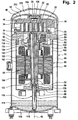
- a first embodiment of a compressor according to the invention shown in Figs. 1 to 5, comprises an outer housing designated as a whole by 10, in which a generally designated 12 spiral compressor is arranged, which by a designated as a whole with 14 drive unit is drivable.
- the scroll compressor 12 comprises a first compressor body 16 and a second compressor body 18, wherein the first compressor body 16 a above a floor 20 of the same uplifting first, in the form of a Circular involute trained spiral rib 22 and the second compressor body 18 a rising above a floor 24 of the same second in shape a spiral involute trained spiral rib 26, wherein the spiral ribs 22, 26 engage each other and in each case on the bottom surfaces 28th or 30 of the other compressor body 18, 16 sealingly abut, so that between the spiral ribs 22, 26 and the bottom surfaces 28, 30 of the Compressor body 16, 18 form chambers 32, in which a compression a refrigerant takes place via one of the spiral ribs 22, 26 radially outward surrounding intake 34 flows with initial pressure and after the Compressing in the chambers 28 via an outlet 36, provided in the bottom 20th of the first compressor body 16, compressed to high pressure emerges.
- the first compressor body 16 firmly held in the outer housing 10, by means of a Separator 40, which in turn on the outer housing 10 within the same is held, the bottom 20 of the first compressor body 16 at a distance engages and tight with an around the outlet 36 extending annular flange 42 of the first compressor body 16, which over the bottom 20 on one of the spiral rib 26 opposite side protrudes, is connected.
- a cooling chamber 44 for cooling the bottom 20 of the first Compressor body 16 is formed, for example, the subject of WO 02/052205 A2, in which the cooling of the scroll compressor 12 is described.
- the second compressor body 18 In contrast to the first compressor body 16, the second compressor body 18 about a central axis 46 on an orbital path relative to the first Compressor body 16 movable, wherein the spiral ribs 22 and 26 theoretically abut each other along a line of contact and the line of contact also during the movement of the second compressor body 18 on the orbital path revolving around the central axis 46.
- the drive of the second compressor body 18 on the orbital track to the Central axis 46 is effected by the already mentioned drive unit 14, which an eccentric 50, a drive shaft 50 driving the eccentric drive 52, a drive motor 54 and a bearing unit 56 for supporting the Drive shaft 52 includes.
- the eccentric 50 is formed by an eccentric on the drive shaft 52 and thus arranged eccentrically to the central axis 46
- Driver 62 which in a fixed to the bottom 24 of the second compressor body 18 connected driver receptacle 64 engages to thus the second compressor body 18 on the orbital path about the central axis 46 to move.
- the bearing unit 56 in turn comprises a first bearing body 66, which represents a main bearing body and with a bearing portion 68 the Drive shaft 52 supports in a region 70 and which the driver 62nd carries, wherein the driver 62 preferably in one piece to the area 70th is arranged.
- the first bearing body 66 encloses a space 72, in which the Eccentric 50 is arranged and in which a fixed to the Drive shaft 52 connected balancing mass 74 moves.
- first bearing body 66 extends laterally of the space 72 in Direction of the bottom 24 of the second compressor body 18 and has a the second compressor body 18 facing opening 76 of the space 72nd around extending wings 78, on which the second compressor body 18 with one of the second spiral rib 26 opposite back 80 rests and thus supported so that the second compressor body 18th thereby secured against movement away from the first compressor body 16 is.
- the fixation of the first bearing body 66 in the outer housing 10 takes place doing so with retaining arms 82 extending radially from the first bearing body 66 to the Outer housing 10 extend and in this the first bearing body 66 precisely hold.
- the first bearing body 66 further has on a holding arms 82 opposite Side on an outer surface 84, on which a within and at a distance from a cylindrical portion 86 of the outer housing 10th extending, preferably also cylindrical housing sleeve 88 of a Motor housing 90 sits, extending to a second floor of the motor housing 90 forming bearing body 92 extends, the distance from the first Bearing body 66 is arranged and forms a bearing portion 94, in which the drive shaft 52 with an end portion 96 coaxial with the central axis 46th is stored.
- the entire motor housing 90 thus extends within the cylindrical Section 86 of the outer housing 10 and at a distance from this.
- the motor housing 90 is between the first bearing body 66 and the second bearing body 92 of the drive motor 54 is arranged, which one on the drive shaft 52 seated rotor 100 and a rotor 100 surrounding Stator 102, wherein the stator 102 of the housing sleeve 88 of the Motor housing 90 is held stably fixed relative to the outer housing 10, so That is, a conventional gap 104 between the rotor 100 and the stator 102nd consists.
- stator 102 facing the housing sleeve 88 on its Side provided with cooling channels 106 which are parallel to the central axis 46, for example in the form of outer grooves, in the stator 102 over the entire plant side 108 run, wherein the stator 102 via the plant side 108 is supported on the housing sleeve 88.
- a free space 112 is provided between the second bearing body 92 and a bottom part 110 of the outer housing 10 , which opens up the possibility that at about the bottom portion 110 with approximately vertically extending central axis 46 elevating outer housing 10 forms an oil sump 114, in which on the one hand lubricating oil accumulates due to gravity and on the other hand Lubricating oil for lubricating the compressor according to the invention ready is held.
- oil sump 114 emerges from the end portion 96 of the Drive shaft 52 and coaxial with this extending oil delivery pipe 116, which has in its interior 118 a conveyor wing 120 and thus acting as an oil pump, which oil from the oil sump 114 in a drive shaft 52 passing lubricating oil passage 122 which pumps via an orifice 124 lubricating oil on an end face 126 of the driver 62 emerge leaves one between the cam receiver 64 and the driver 62nd formed pivot bearing for the movement of the second compressor body 18 lubricate the orbital track.
- the used for lubrication of the driver 62 in the driver seat 64 Oil leaves the driver seat 64 in the area of the area 70 facing opening 132 of the cam receiver 64, then arrives a bottom 134 of the space 70 formed by the first bearing body 66 and from this via drainage channels 136 which communicate with the bottom 134 an oil guide form, in an upper interior 140 of the motor housing 90. Further occurs Oil, the lubrication of the area 70 of the drive shaft 52 in the bearing section 68 serves, on an underside 142 of the bearing portion 68 of this from and thus also in the upper interior 140 of the motor housing 90 a.
- the suction port 152 has a sleeve 154 which is the Outer housing 10 of the compressor according to the invention interspersed and in a fixed to the housing sleeve 88 of the motor housing 90 connected recording 156 engages, as shown in FIGS. 1 and 3.
- the receptacle 156 encloses while a provided in the housing sleeve 88 inlet 158 for the refrigerant, so that this directly into a lower interior 160 of the motor housing 90 may occur between the stator 102 and the second Bearing body 92 is located.
- the inlet opening 158 is arranged in the direction of the central axis 46, that the refrigerant in the amount of a winding head 162 of the stator 102 in the lower interior 160 enters, which also projects into the interior 160.
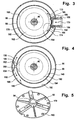
- the inlet 158 associated with a deflection unit 164, which two deflection surfaces 166 and 168, the approximately in the radial direction 170 to Center axis 46 through the sleeve 154 inflowing refrigerant so that Main flow directions of the supplied gaseous refrigerant in two opposite Azimuthalraumen 172 and 174 to the central axis 46 to the Winding 162 run around and within the housing sleeve 88, the inner wall 176 of which is in the azimuthal directions 172 and 174 spreading refrigerant continues and helps that with the supplied Refrigerant entrained oil deposited on the inner wall 176 is and at this in the direction of in Fig.
- second Bearing body 92 runs down. Wherein the bearing body 92 and the Housing sleeve 88 forms substantially occlusive bottom 178, the However, with oil drain holes 180 is provided, from which the separating oil can drain into the oil sump 114.
- Due to the closed bottom 178 has in the lower interior 160th the motor housing 90 entering refrigerant substantially not the Possibility, in the free space 112 between the second bearing body 92nd and the bottom part 110, but remains substantially in the inner space 160 for cooling the winding head 162 and then enters starting from the inner space 160 through the cooling channels 106 and the gap 104 between the rotor 100 and the stator 102 in the upper interior 140th over which lies between the first bearing body 66 and the stator 102 to the projecting into the upper interior 140 winding heads 182 to cool.
- the gap 188 is in substantially between an inner wall surface 192 of the cylindrical portion 86 of the outer housing 10 and an outer wall surface 194 of the cylindrical Housing sleeve 88 is located, wherein the gap 188 preferably as closed annulus extends around the housing sleeve 88 around.
- the outlet opening 184 is arranged opposite a deflection unit 200, which deflection surfaces 202 and 204, that from the outlet opening 184 leaking gaseous refrigerant in the azimuthal Divert directions 196 and 198.
- an oil separator effect especially in a precipitate of oil released by the Refrigerant is carried on the inner wall surface 192 and the outer wall surface 194, the oil being at a substantially vertical center axis 46 positioned compressor between the outer housing 10 and the Motor housing 90 preferably along the inner wall surface 192 and the Outer wall surface 194 can run in the direction of the oil sump 114, since between the outer housing 10 and the motor housing 90 over the entire Extension of the motor housing 90 in the direction of the central axis 46 a starting from the gap 188 in the free space 112 passing There is free space 206 over which the oil ultimately the oil sump 114 can be fed.
- the deposition of all takes place from the refrigerant on its way through the interior 160, through the gap 104 and the Cooling channels 106 and the interior 140 entrained oil, in particular at least partially also oil, which at the bottom 142 of the bearing section 68 exits, and oil, which is supplied via the drain channels 136 to the interior 140 has been.
- the refrigerant thus substantially freed of oil in the oil separator 190 then flows starting from the gap 188 of the oil separator 190th between the holding arms 82 and thus outside of the first bearing body 66 over in the direction of the suction portion 34 of the scroll compressor 12 and is sucked by this and compressed, the compressed refrigerant through the outlet 36 enters a pressure space 210 which is between a lid 212 the outer housing 10 and the separator body 40 is located and by this a pressure port 214 is discharged.
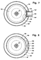
- the suction port 152 ' is arranged so that the inlet 158' is at the level of the winding head 182 of the stator 102 and thus the supplied Refrigerant first in the upper interior 140 within the Motor housing 90 enters, then also through the gap 104 between the Rotor 100 and the stator 102 and also provided cooling channels 106 in the lower interior 160 enters to in this the winding head 162 to cool.
- the central axis 46 extend over the entire length of the housing sleeve 88 to the support arms 82 of the first Bearing body 66, so that seen in the direction of the central axis 46, a longer Gap between the outer housing 10 and the housing sleeve 88 for the oil separation is available.
- the exit port 184 ' is also opposite one Deflection unit 200 'associated, the deflection surfaces 202' and 204 'also a deflection of the exiting refrigerant in the azimuthal directions 196th and 198 in the gap 188 'effect.
- a third embodiment of a compressor according to the invention shown in Fig. 9, those parts are the same as those of the first embodiment are identical, provided with the same reference numerals, so that in full reference to the comments on the first embodiment can be taken.
- the drain channels 136 not so that the oil in the Room 140 enters, but so far through the first bearing body 66 therethrough and through the housing sleeve 88 therethrough in the radial direction to the central axis 46 to the outside, that the oil enters the gap 188 and in this together with the separated in the space 188 oil, preferably by the free space 206, the oil sump 114 in the free space 112 to flow can.
Landscapes
- Engineering & Computer Science (AREA)
- Mechanical Engineering (AREA)
- General Engineering & Computer Science (AREA)
- Rotary Pumps (AREA)
- Applications Or Details Of Rotary Compressors (AREA)
- Compressor (AREA)
Description
- Fig. 1
- einen Längsschnitt durch ein erstes Ausführungsbeispiel eines erfindungsgemäßen Kompressors;
- Fig. 2
- einen um einen Winkel von ungefähr 90° gedrehten Längsschnitt durch das erste Ausführungsbeispiel des erfindungsgemäßen Kompressors;
- Fig. 3
- einen Schnitt längs Linie 3-3 in Fig. 1;
- Fig. 4
- einen Schnitt längs Linie 4-4 in Fig. 1;
- Fig. 5
- eine Draufsicht auf einen Boden eines Motorgehäuse bildendes zweites Lagerteil;
- Fig. 6
- eine Ansicht ähnlich Fig. 1 eines zweiten Ausführungsbeispiels eines erfindungsgemäßen Kompressors;
- Fig. 7
- einen Schnitt längs Linie 7-7 in Fig. 6;
- Fig. 8
- einen Schnitt längs Linie 8-8 in Fig. 6 und
- Fig. 9
- einen Schnitt ähnlich Fig. 2 durch ein drittes Ausführungsbeispiel eines erfindungsgemäßen Kompressors.
Claims (35)
- Kompressor für Kältemittel, umfassend
ein Außengehäuse (10),
einen in dem Außengehäuse angeordneten Spiralverdichter (12) mit einem ersten, feststehend im Außengehäuse (10) angeordneten Verdichterkörper (16) und einem zweiten relativ zum ersten Verdichterkörper (16) bewegbaren Verdichterkörper (18), die jeweils einen Boden (20, 24)und sich über dem jeweiligen Boden (20, 24) erhebende erste bzw. zweite Spiralrippen (22, 26) aufweisen, welche so ineinandergreifen, daß zum Verdichten des Kältemittels der zweite Verdichterkörper (18) gegenüber dem ersten Verdichterkörper (16) auf einer Orbitalbahn um eine Mittelachse (46) bewegbar ist,
eine Antriebseinheit (14) für den zweiten Verdichterkörper (18) mit einem Exzenterantrieb (50), einer Antriebswelle (52), einem in einem Motorgehäuse (90) angeordneten und vom angesaugten Kältemittel umströmten Antriebsmotor (54) sowie einer Lagereinheit (56) für die Antriebswelle, welche einen ersten, mit dem Außengehäuse (10) verbundenen Lagerkörper (66) umfaßt,
dadurch gekennzeichnet, daß das Kältemittel nach Umströmen des Antriebsmotors (54) und vor Eintritt in den Spiralverdichter (12) einen Ölabscheider (190) durchströmt, welcher in dem Außengehäuse (10) zwischen diesem und der Antriebseinheit (14) angeordnet ist. - Kompressor nach Anspruch 1, dadurch gekennzeichnet, daß der Ölabscheider (190) in einem in Richtung quer zur Mittelachse (46) zwischen dem Außengehäuse (10) und der Antriebseinheit (14) liegenden Zwischenraum (188) angeordnet ist.
- Kompressor nach Anspruch 1 oder 2, dadurch gekennzeichnet, daß sich der Zwischenraum (188, 206) zwischen dem Außengehäuse (10) und der Antriebseinheit (14) im wesentlichen über die gesamte Erstreckung der Antriebseinheit (14) in Richtung parallel zur Mittelachse (46) erstreckt.
- Kompressor nach Anspruch 2 oder 3, dadurch gekennzeichnet, daß der Zwischenraum (188, 206) die Antriebseinheit (14) umgibt.
- Kompressor nach einem der Ansprüche 2 bis 4, dadurch gekennzeichnet, daß sich in dem Zwischenraum (188, 206) vom Ölabscheider (190) abgeschiedenes Öl in Richtung des Ölsumpfes (114) bewegt und Kältemittel in Richtung eines Ansaugraums (34) des Spiralverdichters (12) strömt.
- Kompressor nach einem der Ansprüche 2 bis 5, dadurch gekennzeichnet, daß Kältemittel nach Kühlung des Antriebsmotors (54) in den Zwischenraum (188, 206) eintritt.
- Kompressor nach einem der voranstehenden Ansprüche, dadurch gekennzeichnet, daß der Ölabscheider (190) zumindest abschnittsweise auf einer Außenseite des ersten Lagerkörpers (66) angeordnet ist.
- Kompressor nach Anspruch 7, dadurch gekennzeichnet, daß der Ölabscheider (190) zumindest abschnittsweise den ersten Lagerkörper (66) umgebend angeordnet ist.
- Kompressor nach einem der voranstehenden Ansprüche, dadurch gekennzeichnet, daß der Ölabscheider (190) zumindest abschnittsweise auf einer Außenseite des Motorgehäuses (90) angeordnet ist.
- Kompressor nach Anspruch 9, dadurch gekennzeichnet, daß der Ölabscheider (190) zumindest abschnittsweise das Motorgehäuse (90) umgebend angeordnet ist.
- Kompressor nach einem der voranstehenden Ansprüche, dadurch gekennzeichnet, daß der Ölabscheider (190) einen Teil des zwischen dem Außengehäuse (10) und der Antriebseinheit (14) liegenden Zwischenraum (188) nutzt.
- Kompressor nach Anspruch 11, dadurch gekennzeichnet, daß der vom Ölabscheider (190) genutzte Zwischenraum (188) zwischen dem Außengehäuse (10) und der Antriebseinheit (14) ein Ringraum ist.
- Kompressor nach einem der voranstehenden Ansprüche, dadurch gekennzeichnet, daß das Kältemittel bei Eintritt in den Ölabscheider (190) eine Umlenkung in azimutaler Richtung (196, 198) zu der Mittelachse (46) erfährt.
- Kompressor nach Anspruch 13, dadurch gekennzeichnet, daß das Kältemittel eine Umlenkung in entgegengesetzte azimutale Richtungen (196, 198) erfährt.
- Kompressor nach einem der voranstehenden Ansprüche, dadurch gekennzeichnet, daß das Kältemittel im Ölabscheider (190) im wesentlichen auf einer azimutalen Bahn um die Mittelachse (46) geführt ist.
- Kompressor nach einem der voranstehenden Ansprüche, dadurch gekennzeichnet, daß das Kältemittel im Ölabscheider (190) längs einer Innenwandfläche (192) des Außengehäuses (10) strömt.
- Kompressor nach einem der voranstehenden Ansprüche, dadurch gekennzeichnet, daß das sich im Ölabscheider (190) niederschlagende Öl auf einem außerhalb des Motorgehäuses (90) verlaufenden Weg in einen Ölsumpf (114) fließt.
- Kompressor nach einem der voranstehenden Ansprüche, dadurch gekennzeichnet, daß der Ölsumpf (114) im Außengehäuse (10) auf einer dem ersten Lagerkörper (66) gegenüberliegenden Seite des Antriebsmotors (54) angeordnet ist.
- Kompressor nach einem der voranstehenden Ansprüche, dadurch gekennzeichnet, daß das Kältemittel auf seinem Weg vom Ölabscheider (190) zum Ansaugraum (34) des Spiralverdichters (12) eine Außenseite des ersten Lagerkörpers (66) umströmt.
- Kompressor nach einem der voranstehenden Ansprüche, dadurch gekennzeichnet, daß der Ölabscheider auf einer dem Ölsumpf zugewandten Seite von den den ersten Lagerkörper mit dem Außengehäuse verbindenden Haltearmen liegt.
- Kompressor nach Anspruch 20, dadurch gekennzeichnet, daß das Kältemittel nach Durchströmen des Ölabscheiders (190) zwischen den Haltearmen (82) hindurch in Richtung eines Ansaugraums (34) des Spiralverdichters (12) strömt.
- Kompressor nach einem der voranstehenden Ansprüche, dadurch gekennzeichnet, daß das Kältemittel bei Eintritt in den Kompressor unmittelbar in das Motorgehäuse (90) einströmt und nach Durchströmen des Motorgehäuses (90) in den Ölabscheider (190) eintritt.
- Kompressor nach einem der voranstehenden Ansprüche, dadurch gekennzeichnet, daß das in das Motorgehäuse (90) eintretende Kältemittel eine Umlenkung in mindestens einer Azimutalrichtung (172, 174) erfährt.
- Kompressor nach Anspruch 23, dadurch gekennzeichnet, daß das in das Motorgehäuse (90) eintretende Kältemittel eine Umlenkung in entgegengesetzte Azimutalrichtungen (172, 174) erfährt.
- Kompressor nach einem der voranstehenden Ansprüche, dadurch gekennzeichnet, daß das Kältemittel in Richtung der Mittelachse (46) gesehen in Höhe eines ersten Wicklungskopfes (162, 182) in das Motorgehäuse (90) eintritt.
- Kompressor nach Anspruch 25, dadurch gekennzeichnet, daß das Kältemittel in Richtung der Mittelachse (46) gesehen, den Antriebsmotor (54) vom ersten Wicklungskopf (162, 182) in Richtung eines zweiten Wicklungskopfes ( 182, 162) durchströmt.
- Kompressor nach Anspruch 25 oder 26, dadurch gekennzeichnet, daß das Kältemittel in Höhe des zweiten Wicklungskopfes (182, 162) aus dem Motorgehäuse (90) austritt.
- Kompressor nach einem der voranstehenden Ansprüche, dadurch gekennzeichnet, daß sich im Motorgehäuse (90) abscheidendes Öl durch Ölablauföffnungen (180) in einem Boden (92) des Motorgehäuses (90) aus dem Motorgehäuse (90) austritt, um in den Ölsumpf (114) zu gefangen.
- Kompressor nach einem der voranstehenden Ansprüche, dadurch gekennzeichnet, daß der erste Lagerkörper (66) eine Ölführung (134, 136) für zur Schmierung des Exzenterantriebs (50) eingesetztes Öl aufweist.
- Kompressor nach Anspruch 29, dadurch gekennzeichnet, daß die Ölführung (134, 136) in einen Innenraum (140) des Motorgehäuses (90) mündet.
- Kompressor nach Anspruch 30, dadurch gekennzeichnet, daß Öl zu erheblichen Teilen von dem den Innenraum (140) des Motorgehäuses (90) durchströmenden Kältemittel zum Ölabscheider (190) gefördert wird.
- Kompressor nach Anspruch 29, dadurch gekennzeichnet, daß die Ölführung (134, 136) in den Zwischenraum (188) mündet.
- Kompressor nach einem der voranstehenden Ansprüche, dadurch gekennzeichnet, daß die Antriebswelle (52) eine Schmierölbohrung (122) aufweist.
- Kompressor nach Anspruch 33, dadurch gekennzeichnet, daß über die Schmierölbohrung (122) eine Schmierung eines Drehlagers (68, 70) für die Antriebswelle (52) in dem ersten Lagerkörper (66) erfolgt.
- Kompressor nach Anspruch 33 oder 34, dadurch gekennzeichnet, daß über die Schmierölbohrung (122) eine Schmierung des Exzenterantriebs (50) erfolgt.
Priority Applications (1)
| Application Number | Priority Date | Filing Date | Title |
|---|---|---|---|
| SI200330206T SI1413758T1 (sl) | 2002-10-15 | 2003-10-08 | Spiralni zgoscevalnik z lovilnikom olja |
Applications Claiming Priority (2)
| Application Number | Priority Date | Filing Date | Title |
|---|---|---|---|
| DE10248926A DE10248926B4 (de) | 2002-10-15 | 2002-10-15 | Kompressor |
| DE10248926 | 2002-10-15 |
Publications (3)
| Publication Number | Publication Date |
|---|---|
| EP1413758A2 EP1413758A2 (de) | 2004-04-28 |
| EP1413758A3 EP1413758A3 (de) | 2004-05-19 |
| EP1413758B1 true EP1413758B1 (de) | 2005-12-28 |
Family
ID=32049492
Family Applications (3)
| Application Number | Title | Priority Date | Filing Date |
|---|---|---|---|
| EP12175341.2A Expired - Lifetime EP2511531B1 (de) | 2002-10-15 | 2003-08-20 | Spiralverdichter für Kältemittel |
| EP03808684.9A Expired - Lifetime EP1563189B1 (de) | 2002-10-15 | 2003-08-20 | Spiralverdichter für kältemittel |
| EP03022491A Expired - Lifetime EP1413758B1 (de) | 2002-10-15 | 2003-10-08 | Spiralverdichter mit Ölabscheider |
Family Applications Before (2)
| Application Number | Title | Priority Date | Filing Date |
|---|---|---|---|
| EP12175341.2A Expired - Lifetime EP2511531B1 (de) | 2002-10-15 | 2003-08-20 | Spiralverdichter für Kältemittel |
| EP03808684.9A Expired - Lifetime EP1563189B1 (de) | 2002-10-15 | 2003-08-20 | Spiralverdichter für kältemittel |
Country Status (9)
| Country | Link |
|---|---|
| US (2) | US6960070B2 (de) |
| EP (3) | EP2511531B1 (de) |
| CN (3) | CN102116293B (de) |
| AT (1) | ATE314578T1 (de) |
| DE (2) | DE10248926B4 (de) |
| DK (1) | DK1413758T3 (de) |
| ES (1) | ES2254846T3 (de) |
| SI (1) | SI1413758T1 (de) |
| WO (1) | WO2004036044A1 (de) |
Cited By (1)
| Publication number | Priority date | Publication date | Assignee | Title |
|---|---|---|---|---|
| WO2017001966A1 (ja) * | 2015-06-23 | 2017-01-05 | ジョンソンコントロールズ ヒタチ エア コンディショニング テクノロジー(ホンコン)リミテッド | 圧縮機及び冷凍サイクル装置 |
Families Citing this family (87)
| Publication number | Priority date | Publication date | Assignee | Title |
|---|---|---|---|---|
| DE10248926B4 (de) * | 2002-10-15 | 2004-11-11 | Bitzer Kühlmaschinenbau Gmbh | Kompressor |
| US7179069B2 (en) * | 2004-08-25 | 2007-02-20 | Copeland Corporation | Motor compressor lubrication |
| FR2885966B1 (fr) * | 2005-05-23 | 2011-01-14 | Danfoss Commercial Compressors | Compresseur frigorifique a spirales |
| DE102005048093A1 (de) * | 2005-09-30 | 2007-04-05 | Bitzer Kühlmaschinenbau Gmbh | Kompressor für Kältemittel |
| KR100738708B1 (ko) * | 2005-12-29 | 2007-07-12 | 엘지전자 주식회사 | 스크롤 압축기의 진동방지장치 |
| WO2008088111A1 (en) * | 2007-01-15 | 2008-07-24 | Lg Electronics Inc. | Compressor and oil separating device therefor |
| WO2008088112A1 (en) * | 2007-01-19 | 2008-07-24 | Lg Electronics Inc. | Compressor and oil blocking device therefor |
| KR100869929B1 (ko) * | 2007-02-23 | 2008-11-24 | 엘지전자 주식회사 | 스크롤 압축기 |
| KR100867623B1 (ko) * | 2007-03-21 | 2008-11-10 | 엘지전자 주식회사 | 압축기의 진동 저감장치 |
| KR100882481B1 (ko) * | 2007-04-25 | 2009-02-06 | 엘지전자 주식회사 | 스크롤 압축기의 오일 공급구조 |
| DE102007032157A1 (de) * | 2007-07-03 | 2009-01-08 | Bitzer Kühlmaschinenbau Gmbh | Kompressor |
| FR2919689B1 (fr) * | 2007-08-02 | 2013-07-26 | Danfoss Commercial Compressors | Compresseur frigorifique a spirales |
| US7963753B2 (en) * | 2008-01-17 | 2011-06-21 | Bitzer Kuhlmaschinenbau Gmbh | Scroll compressor bodies with scroll tip seals and extended thrust region |
| US8152500B2 (en) * | 2008-01-17 | 2012-04-10 | Bitzer Scroll Inc. | Scroll compressor build assembly |
| US7967581B2 (en) | 2008-01-17 | 2011-06-28 | Bitzer Kuhlmaschinenbau Gmbh | Shaft mounted counterweight, method and scroll compressor incorporating same |
| US7997877B2 (en) | 2008-01-17 | 2011-08-16 | Bitzer Kuhlmaschinenbau Gmbh | Scroll compressor having standardized power strip |
| US7878780B2 (en) | 2008-01-17 | 2011-02-01 | Bitzer Kuhlmaschinenbau Gmbh | Scroll compressor suction flow path and bearing arrangement features |
| US7878775B2 (en) * | 2008-01-17 | 2011-02-01 | Bitzer Kuhlmaschinenbau Gmbh | Scroll compressor with housing shell location |
| US9568002B2 (en) | 2008-01-17 | 2017-02-14 | Bitzer Kuehlmaschinenbau Gmbh | Key coupling and scroll compressor incorporating same |
| US7918658B2 (en) | 2008-01-17 | 2011-04-05 | Bitzer Scroll Inc. | Non symmetrical key coupling contact and scroll compressor having same |
| US7993117B2 (en) * | 2008-01-17 | 2011-08-09 | Bitzer Scroll Inc. | Scroll compressor and baffle for same |
| US8142175B2 (en) | 2008-01-17 | 2012-03-27 | Bitzer Scroll Inc. | Mounting base and scroll compressor incorporating same |
| US20090185927A1 (en) * | 2008-01-17 | 2009-07-23 | Bitzer Scroll Inc. | Key Coupling and Scroll Compressor Incorporating Same |
| JP5247194B2 (ja) * | 2008-03-19 | 2013-07-24 | 三洋電機株式会社 | スクロール圧縮機 |
| US8133043B2 (en) * | 2008-10-14 | 2012-03-13 | Bitzer Scroll, Inc. | Suction duct and scroll compressor incorporating same |
| US8167595B2 (en) * | 2008-10-14 | 2012-05-01 | Bitzer Scroll Inc. | Inlet screen and scroll compressor incorporating same |
| EP2389516B1 (de) | 2009-01-23 | 2024-01-10 | BITZER Kühlmaschinenbau GmbH | Verdichter mit unterschiedlichen volumenindizes sowie verfahren dafür |
| JP5491420B2 (ja) * | 2009-01-30 | 2014-05-14 | パナソニック株式会社 | スクロール圧縮機 |
| US8167597B2 (en) * | 2009-03-23 | 2012-05-01 | Bitzer Scroll Inc. | Shaft bearings, compressor with same, and methods |
| US8328543B2 (en) * | 2009-04-03 | 2012-12-11 | Bitzer Kuehlmaschinenbau Gmbh | Contoured check valve disc and scroll compressor incorporating same |
| JP4862925B2 (ja) * | 2009-07-31 | 2012-01-25 | 株式会社富士通ゼネラル | ロータリ圧縮機 |
| US8297958B2 (en) | 2009-09-11 | 2012-10-30 | Bitzer Scroll, Inc. | Optimized discharge port for scroll compressor with tip seals |
| JP5370425B2 (ja) * | 2011-07-19 | 2013-12-18 | ダイキン工業株式会社 | 圧縮機 |
| KR101285617B1 (ko) * | 2011-09-09 | 2013-07-23 | 엘지전자 주식회사 | 스크롤 압축기 |
| FR2981739B1 (fr) * | 2011-10-20 | 2018-03-02 | Danfoss Commercial Compressors | Compresseur frigorifique |
| CN102493847B (zh) * | 2011-11-16 | 2013-05-22 | 陈冬长 | 一种涡旋膨胀发电机及朗肯循环热电转换系统 |
| KR101882713B1 (ko) * | 2012-02-27 | 2018-07-27 | 엘지전자 주식회사 | 스크롤 압축기 |
| US8920139B2 (en) * | 2012-03-23 | 2014-12-30 | Bitzer Kuehlmaschinenbau Gmbh | Suction duct with stabilizing ribs |
| US9011105B2 (en) | 2012-03-23 | 2015-04-21 | Bitzer Kuehlmaschinenbau Gmbh | Press-fit bearing housing with large gas passages |
| US9920762B2 (en) | 2012-03-23 | 2018-03-20 | Bitzer Kuehlmaschinenbau Gmbh | Scroll compressor with tilting slider block |
| US9080446B2 (en) | 2012-03-23 | 2015-07-14 | Bitzer Kuehlmaschinenbau Gmbh | Scroll compressor with captured thrust washer |
| US9458850B2 (en) | 2012-03-23 | 2016-10-04 | Bitzer Kuehlmaschinenbau Gmbh | Press-fit bearing housing with non-cylindrical diameter |
| US9181949B2 (en) | 2012-03-23 | 2015-11-10 | Bitzer Kuehlmaschinenbau Gmbh | Compressor with oil return passage formed between motor and shell |
| US9441631B2 (en) | 2012-03-23 | 2016-09-13 | Bitzer Kuehlmaschinenbau Gmbh | Suction duct with heat-staked screen |
| US8876496B2 (en) | 2012-03-23 | 2014-11-04 | Bitzer Kuehlmaschinenbau Gmbh | Offset electrical terminal box with angled studs |
| US9909586B2 (en) | 2012-03-23 | 2018-03-06 | Bitzer Kuehlmaschinenbau Gmbh | Crankshaft with aligned drive and counterweight locating features |
| US9057269B2 (en) | 2012-03-23 | 2015-06-16 | Bitzer Kuehlmaschinenbau Gmbh | Piloted scroll compressor |
| US9051835B2 (en) | 2012-03-23 | 2015-06-09 | Bitzer Kuehlmaschinenbau Gmbh | Offset electrical terminal box with angled studs |
| US9022758B2 (en) | 2012-03-23 | 2015-05-05 | Bitzer Kuehlmaschinenbau Gmbh | Floating scroll seal with retaining ring |
| US10233927B2 (en) | 2012-03-23 | 2019-03-19 | Bitzer Kuehlmaschinenbau Gmbh | Scroll compressor counterweight with axially distributed mass |
| US9181940B2 (en) | 2012-03-23 | 2015-11-10 | Bitzer Kuehlmaschinenbau Gmbh | Compressor baseplate with stiffening ribs for increased oil volume and rail mounting without spacers |
| US9039384B2 (en) | 2012-03-23 | 2015-05-26 | Bitzer Kuehlmaschinenbau Gmbh | Suction duct with adjustable diametric fit |
| JP6015055B2 (ja) * | 2012-03-27 | 2016-10-26 | 株式会社富士通ゼネラル | ロータリ圧縮機 |
| FR2989433B1 (fr) * | 2012-04-16 | 2018-10-12 | Danfoss Commercial Compressors | Compresseur a spirales |
| US10352308B2 (en) | 2012-12-18 | 2019-07-16 | Emerson Climate Technologies, Inc. | Reciprocating compressor with vapor injection system |
| CN105443388B (zh) | 2014-06-10 | 2018-09-04 | 丹佛斯(天津)有限公司 | 用于涡旋压缩机的机架和涡旋压缩机 |
| CN105443377A (zh) * | 2014-06-10 | 2016-03-30 | 丹佛斯(天津)有限公司 | 涡旋压缩机 |
| US9856874B2 (en) | 2014-09-26 | 2018-01-02 | Bitzer Kuehlmaschinenbau Gmbh | Holding plate for piloted scroll compressor |
| CN104406318A (zh) * | 2014-12-24 | 2015-03-11 | 无锡五洋赛德压缩机有限公司 | 小型螺杆式制冷机组 |
| WO2016181445A1 (ja) * | 2015-05-08 | 2016-11-17 | 三菱電機株式会社 | 圧縮機 |
| US10626870B2 (en) | 2015-06-11 | 2020-04-21 | Bitzer Kuehlmaschinenbau Gmbh | Ring weld blocker in discharge check valve |
| US9777731B2 (en) | 2015-06-16 | 2017-10-03 | Bitzer Kuehlmaschinenbau Gmbh | Duct-mounted suction gas filter |
| US9951772B2 (en) * | 2015-06-18 | 2018-04-24 | Bitzer Kuehlmaschinenbau Gmbh | Scroll compressor with unmachined separator plate and method of making same |
| US9890784B2 (en) | 2015-06-30 | 2018-02-13 | Bitzer Kuehlmaschinenbau Gmbh | Cast-in offset fixed scroll intake opening |
| US11078913B2 (en) * | 2015-06-30 | 2021-08-03 | Bitzer Kuehlmaschinenbau Gmbh | Two-piece suction fitting |
| US10132317B2 (en) | 2015-12-15 | 2018-11-20 | Bitzer Kuehlmaschinenbau Gmbh | Oil return with non-circular tube |
| US10697454B2 (en) | 2016-03-08 | 2020-06-30 | Bitzer Kuehlmaschinenbau Gmbh | Method of making a two-piece counterweight for a scroll compressor |
| JP7084109B2 (ja) * | 2017-03-17 | 2022-06-14 | 三菱重工サーマルシステムズ株式会社 | 圧縮機 |
| FR3082568B1 (fr) * | 2018-06-19 | 2021-08-27 | Danfoss Commercial Compressors | Compresseur a spirales muni d'un deflecteur d'enroulement de stator |
| JP6696533B2 (ja) * | 2018-06-22 | 2020-05-20 | ダイキン工業株式会社 | 冷凍装置 |
| CN110319014B (zh) * | 2019-03-20 | 2020-07-31 | 浙江华荣电池股份有限公司 | 电动车用涡旋式空调压缩机 |
| CN111852852A (zh) * | 2019-04-26 | 2020-10-30 | 艾默生环境优化技术(苏州)有限公司 | 一种涡旋压缩机 |
| CN113123972B (zh) * | 2019-12-31 | 2023-06-06 | 丹佛斯(天津)有限公司 | 油泵和涡旋压缩机 |
| CN114076101A (zh) * | 2020-08-17 | 2022-02-22 | 艾默生环境优化技术(苏州)有限公司 | 涡旋压缩机 |
| WO2022036882A1 (zh) * | 2020-08-17 | 2022-02-24 | 艾默生环境优化技术(苏州)有限公司 | 涡旋压缩机 |
| CN112865395B (zh) * | 2021-03-03 | 2024-07-23 | 江苏华永复合材料有限公司 | 用于高功率密度汽车电机的冷却系统 |
| FR3120661B1 (fr) | 2021-03-10 | 2023-03-10 | Danfoss Commercial Compressors | Compresseur à spirales ayant une pompe à huile centrifuge |
| FR3120662B1 (fr) | 2021-03-10 | 2023-03-03 | Danfoss Commercial Compressors | Compresseur à spirales pourvu d'un agencement de palier inférieur hydrostatique |
| CN113188721B (zh) * | 2021-03-30 | 2021-11-19 | 嘉兴逸合盛制冷科技有限公司 | 一种制冷设备用压缩机的密封性水检设备 |
| CN116265743A (zh) * | 2021-12-17 | 2023-06-20 | 丹佛斯商用压缩机公司 | 设有油槽整流器的压缩机涡旋件 |
| CN217327669U (zh) * | 2021-12-31 | 2022-08-30 | 丹佛斯(天津)有限公司 | 涡旋压缩机 |
| US12259163B2 (en) | 2022-06-01 | 2025-03-25 | Copeland Lp | Climate-control system with thermal storage |
| US11846287B1 (en) | 2022-08-11 | 2023-12-19 | Copeland Lp | Scroll compressor with center hub |
| US11965507B1 (en) | 2022-12-15 | 2024-04-23 | Copeland Lp | Compressor and valve assembly |
| US12416308B2 (en) | 2022-12-28 | 2025-09-16 | Copeland Lp | Compressor with shutdown assembly |
| US12173708B1 (en) | 2023-12-07 | 2024-12-24 | Copeland Lp | Heat pump systems with capacity modulation |
| US12163523B1 (en) | 2023-12-15 | 2024-12-10 | Copeland Lp | Compressor and valve assembly |
Family Cites Families (23)
| Publication number | Priority date | Publication date | Assignee | Title |
|---|---|---|---|---|
| JPS58117378A (ja) * | 1981-12-28 | 1983-07-12 | Mitsubishi Electric Corp | スクロ−ル圧縮機 |
| JPS59176494A (ja) * | 1983-03-26 | 1984-10-05 | Mitsubishi Electric Corp | スクロ−ル圧縮機 |
| JPS59224493A (ja) * | 1983-06-03 | 1984-12-17 | Mitsubishi Electric Corp | スクロ−ル圧縮機 |
| JPS60192894A (ja) * | 1984-03-13 | 1985-10-01 | Mitsubishi Electric Corp | スクロ−ル圧縮機 |
| US4754950A (en) * | 1984-10-30 | 1988-07-05 | Kabushiki Kaisha Toshiba | Valve |
| JPH07111185B2 (ja) * | 1991-10-22 | 1995-11-29 | ダイキン工業株式会社 | 密閉形圧縮機 |
| JPH05157066A (ja) * | 1991-12-05 | 1993-06-22 | Daikin Ind Ltd | スクロール形圧縮機 |
| JP2541181B2 (ja) * | 1991-12-05 | 1996-10-09 | ダイキン工業株式会社 | 弁装置 |
| CN1065324C (zh) | 1993-07-09 | 2001-05-02 | 松下电器产业株式会社 | 涡旋压缩机的止回阀 |
| JP3173253B2 (ja) * | 1993-11-02 | 2001-06-04 | 松下電器産業株式会社 | スクロール圧縮機 |
| US5633094A (en) * | 1994-10-28 | 1997-05-27 | Hitachi, Ltd. | Valve having facing layers of co-free Ni-base Alloy |
| US5741120A (en) * | 1995-06-07 | 1998-04-21 | Copeland Corporation | Capacity modulated scroll machine |
| JPH09112474A (ja) * | 1995-10-17 | 1997-05-02 | Daikin Ind Ltd | 冷媒圧縮機 |
| JPH10274178A (ja) * | 1997-03-27 | 1998-10-13 | Mitsubishi Electric Corp | スクロール圧縮機 |
| KR100223437B1 (ko) * | 1997-10-25 | 1999-10-15 | 윤종용 | 스크롤 압축기의 첵크 밸브 |
| DE19845993A1 (de) * | 1998-10-06 | 2000-04-20 | Bitzer Kuehlmaschinenbau Gmbh | Schraubenverdichter |
| US6179589B1 (en) * | 1999-01-04 | 2001-01-30 | Copeland Corporation | Scroll machine with discus discharge valve |
| JP2000345978A (ja) * | 1999-05-31 | 2000-12-12 | Mitsubishi Heavy Ind Ltd | スクロール型圧縮機 |
| US6227830B1 (en) * | 1999-08-04 | 2001-05-08 | Scroll Technologies | Check valve mounted adjacent scroll compressor outlet |
| US6679683B2 (en) * | 2000-10-16 | 2004-01-20 | Copeland Corporation | Dual volume-ratio scroll machine |
| DE10065821A1 (de) * | 2000-12-22 | 2002-07-11 | Bitzer Kuehlmaschinenbau Gmbh | Kompressor |
| US6537043B1 (en) * | 2001-09-05 | 2003-03-25 | Copeland Corporation | Compressor discharge valve having a contoured body with a uniform thickness |
| DE10248926B4 (de) * | 2002-10-15 | 2004-11-11 | Bitzer Kühlmaschinenbau Gmbh | Kompressor |
-
2002
- 2002-10-15 DE DE10248926A patent/DE10248926B4/de not_active Expired - Fee Related
-
2003
- 2003-08-20 WO PCT/EP2003/009214 patent/WO2004036044A1/de not_active Ceased
- 2003-08-20 CN CN2011100496446A patent/CN102116293B/zh not_active Expired - Lifetime
- 2003-08-20 EP EP12175341.2A patent/EP2511531B1/de not_active Expired - Lifetime
- 2003-08-20 EP EP03808684.9A patent/EP1563189B1/de not_active Expired - Lifetime
- 2003-08-20 CN CN038242281A patent/CN1688817B/zh not_active Expired - Lifetime
- 2003-10-08 DE DE50302045T patent/DE50302045D1/de not_active Expired - Lifetime
- 2003-10-08 AT AT03022491T patent/ATE314578T1/de not_active IP Right Cessation
- 2003-10-08 SI SI200330206T patent/SI1413758T1/sl unknown
- 2003-10-08 US US10/682,304 patent/US6960070B2/en not_active Expired - Lifetime
- 2003-10-08 ES ES03022491T patent/ES2254846T3/es not_active Expired - Lifetime
- 2003-10-08 DK DK03022491T patent/DK1413758T3/da active
- 2003-10-08 EP EP03022491A patent/EP1413758B1/de not_active Expired - Lifetime
- 2003-10-15 CN CNB2003101012455A patent/CN1292171C/zh not_active Expired - Lifetime
-
2005
- 2005-04-11 US US11/104,273 patent/US7112046B2/en not_active Expired - Lifetime
Cited By (1)
| Publication number | Priority date | Publication date | Assignee | Title |
|---|---|---|---|---|
| WO2017001966A1 (ja) * | 2015-06-23 | 2017-01-05 | ジョンソンコントロールズ ヒタチ エア コンディショニング テクノロジー(ホンコン)リミテッド | 圧縮機及び冷凍サイクル装置 |
Also Published As
| Publication number | Publication date |
|---|---|
| DK1413758T3 (da) | 2006-05-08 |
| DE50302045D1 (de) | 2006-02-02 |
| ES2254846T3 (es) | 2006-06-16 |
| US20050232800A1 (en) | 2005-10-20 |
| EP1413758A2 (de) | 2004-04-28 |
| EP2511531A2 (de) | 2012-10-17 |
| EP1563189B1 (de) | 2015-12-09 |
| CN1688817B (zh) | 2012-06-27 |
| ATE314578T1 (de) | 2006-01-15 |
| EP2511531A3 (de) | 2014-05-21 |
| CN1292171C (zh) | 2006-12-27 |
| CN102116293A (zh) | 2011-07-06 |
| US20040126261A1 (en) | 2004-07-01 |
| US7112046B2 (en) | 2006-09-26 |
| CN1688817A (zh) | 2005-10-26 |
| DE10248926A1 (de) | 2004-05-06 |
| EP1413758A3 (de) | 2004-05-19 |
| EP2511531B1 (de) | 2018-03-07 |
| WO2004036044A1 (de) | 2004-04-29 |
| CN102116293B (zh) | 2013-05-01 |
| US6960070B2 (en) | 2005-11-01 |
| DE10248926B4 (de) | 2004-11-11 |
| SI1413758T1 (sl) | 2006-06-30 |
| CN1497182A (zh) | 2004-05-19 |
| EP1563189A1 (de) | 2005-08-17 |
Similar Documents
| Publication | Publication Date | Title |
|---|---|---|
| DE10248926B4 (de) | Kompressor | |
| DE3627579C2 (de) | ||
| DE112006001283B4 (de) | Kältemittelverdichter vom Scroll-Typ | |
| DE69409474T2 (de) | Ölzuführsystem für einen Spiralverdichter | |
| DE4008882C2 (de) | ||
| DE2938276A1 (de) | Fluegelzellenverdichter | |
| EP1036276A1 (de) | Schraubenverdichter | |
| DE3590213T1 (de) | Verdichter | |
| DE19907492A1 (de) | CO¶2¶-Kompressor | |
| EP3657017B1 (de) | Kältemittelverdichter | |
| DE69427186T2 (de) | Schwingender rotations-kompressor | |
| DE102005000899A1 (de) | Ölablassreduziervorrichtung für einen Spiralverdichter | |
| DE2814266A1 (de) | Schmiersystem fuer hermetischen kaelteverdichter | |
| EP2174011B1 (de) | Kompressor mit flüssigkeitströpfchen zerstäubender einströmkammer | |
| DE2332411B2 (de) | Rotationskolbenverdichter | |
| DE69311036T2 (de) | Kurbelwellenschmiersystem | |
| EP1770281B1 (de) | Kompressor für Kältemittel | |
| DE69831024T2 (de) | Spiralverdichter | |
| EP2005001B1 (de) | Zellenpumpe | |
| DE102009017037B4 (de) | Compressor | |
| EP1593852A2 (de) | Umwälzpumpe und Verfahren zur Flüssigkeitsschmierung eines sphärischen Lagers in einem Elektromotor | |
| DE102016103315B4 (de) | Kompressor | |
| DE3444389A1 (de) | Hermetisch abgeschlossener, mit vertikaler achse rotierender motorkompressor | |
| DE4134939A1 (de) | Spiralverdichter mit verbessertem schmiermittelfluss | |
| DE112023004692T5 (de) | Mitdrehender Spiralverdichter |
Legal Events
| Date | Code | Title | Description |
|---|---|---|---|
| PUAI | Public reference made under article 153(3) epc to a published international application that has entered the european phase |
Free format text: ORIGINAL CODE: 0009012 |
|
| PUAL | Search report despatched |
Free format text: ORIGINAL CODE: 0009013 |
|
| AK | Designated contracting states |
Kind code of ref document: A2 Designated state(s): AT BE BG CH CY CZ DE DK EE ES FI FR GB GR HU IE IT LI LU MC NL PT RO SE SI SK TR |
|
| AX | Request for extension of the european patent |
Extension state: AL LT LV MK |
|
| AK | Designated contracting states |
Kind code of ref document: A3 Designated state(s): AT BE BG CH CY CZ DE DK EE ES FI FR GB GR HU IE IT LI LU MC NL PT RO SE SI SK TR |
|
| AX | Request for extension of the european patent |
Extension state: AL LT LV MK |
|
| 17P | Request for examination filed |
Effective date: 20040715 |
|
| 17Q | First examination report despatched |
Effective date: 20040920 |
|
| AKX | Designation fees paid |
Designated state(s): AT BE BG CH CY CZ DE DK EE ES FI FR GB GR HU IE IT LI LU MC NL PT RO SE SI SK TR |
|
| GRAP | Despatch of communication of intention to grant a patent |
Free format text: ORIGINAL CODE: EPIDOSNIGR1 |
|
| RTI1 | Title (correction) |
Free format text: SCROLL COMPRESSOR WITH OIL SEPARATOR |
|
| GRAS | Grant fee paid |
Free format text: ORIGINAL CODE: EPIDOSNIGR3 |
|
| GRAA | (expected) grant |
Free format text: ORIGINAL CODE: 0009210 |
|
| AK | Designated contracting states |
Kind code of ref document: B1 Designated state(s): AT BE BG CH CY CZ DE DK EE ES FI FR GB GR HU IE IT LI LU MC NL PT RO SE SI SK TR |
|
| PG25 | Lapsed in a contracting state [announced via postgrant information from national office to epo] |
Ref country code: CZ Free format text: LAPSE BECAUSE OF FAILURE TO SUBMIT A TRANSLATION OF THE DESCRIPTION OR TO PAY THE FEE WITHIN THE PRESCRIBED TIME-LIMIT Effective date: 20051228 Ref country code: IT Free format text: LAPSE BECAUSE OF FAILURE TO SUBMIT A TRANSLATION OF THE DESCRIPTION OR TO PAY THE FEE WITHIN THE PRESCRIBED TIME-LIMIT;WARNING: LAPSES OF ITALIAN PATENTS WITH EFFECTIVE DATE BEFORE 2007 MAY HAVE OCCURRED AT ANY TIME BEFORE 2007. THE CORRECT EFFECTIVE DATE MAY BE DIFFERENT FROM THE ONE RECORDED. Effective date: 20051228 Ref country code: FI Free format text: LAPSE BECAUSE OF FAILURE TO SUBMIT A TRANSLATION OF THE DESCRIPTION OR TO PAY THE FEE WITHIN THE PRESCRIBED TIME-LIMIT Effective date: 20051228 Ref country code: RO Free format text: LAPSE BECAUSE OF FAILURE TO SUBMIT A TRANSLATION OF THE DESCRIPTION OR TO PAY THE FEE WITHIN THE PRESCRIBED TIME-LIMIT Effective date: 20051228 Ref country code: IE Free format text: LAPSE BECAUSE OF FAILURE TO SUBMIT A TRANSLATION OF THE DESCRIPTION OR TO PAY THE FEE WITHIN THE PRESCRIBED TIME-LIMIT Effective date: 20051228 |
|
| REG | Reference to a national code |
Ref country code: GB Ref legal event code: FG4D Free format text: NOT ENGLISH |
|
| REG | Reference to a national code |
Ref country code: CH Ref legal event code: EP |
|
| REG | Reference to a national code |
Ref country code: IE Ref legal event code: FG4D Free format text: LANGUAGE OF EP DOCUMENT: GERMAN |
|
| REF | Corresponds to: |
Ref document number: 50302045 Country of ref document: DE Date of ref document: 20060202 Kind code of ref document: P |
|
| REG | Reference to a national code |
Ref country code: DE Ref legal event code: R096 Ref document number: 50302045 Country of ref document: DE Effective date: 20060202 |
|
| PG25 | Lapsed in a contracting state [announced via postgrant information from national office to epo] |
Ref country code: BG Free format text: LAPSE BECAUSE OF FAILURE TO SUBMIT A TRANSLATION OF THE DESCRIPTION OR TO PAY THE FEE WITHIN THE PRESCRIBED TIME-LIMIT Effective date: 20060328 |
|
| GBT | Gb: translation of ep patent filed (gb section 77(6)(a)/1977) |
Effective date: 20060322 |
|
| REG | Reference to a national code |
Ref country code: SE Ref legal event code: TRGR |
|
| REG | Reference to a national code |
Ref country code: GR Ref legal event code: EP Ref document number: 20060400818 Country of ref document: GR |
|
| REG | Reference to a national code |
Ref country code: DK Ref legal event code: T3 |
|
| REG | Reference to a national code |
Ref country code: ES Ref legal event code: FG2A Ref document number: 2254846 Country of ref document: ES Kind code of ref document: T3 |
|
| PG25 | Lapsed in a contracting state [announced via postgrant information from national office to epo] |
Ref country code: HU Free format text: LAPSE BECAUSE OF FAILURE TO SUBMIT A TRANSLATION OF THE DESCRIPTION OR TO PAY THE FEE WITHIN THE PRESCRIBED TIME-LIMIT Effective date: 20060629 |
|
| REG | Reference to a national code |
Ref country code: IE Ref legal event code: FD4D |
|
| ET | Fr: translation filed | ||
| PG25 | Lapsed in a contracting state [announced via postgrant information from national office to epo] |
Ref country code: MC Free format text: LAPSE BECAUSE OF NON-PAYMENT OF DUE FEES Effective date: 20061031 |
|
| PLBE | No opposition filed within time limit |
Free format text: ORIGINAL CODE: 0009261 |
|
| STAA | Information on the status of an ep patent application or granted ep patent |
Free format text: STATUS: NO OPPOSITION FILED WITHIN TIME LIMIT |
|
| 26N | No opposition filed |
Effective date: 20060929 |
|
| REG | Reference to a national code |
Ref country code: DE Ref legal event code: R097 Ref document number: 50302045 Country of ref document: DE Effective date: 20060929 |
|
| PGFP | Annual fee paid to national office [announced via postgrant information from national office to epo] |
Ref country code: SK Payment date: 20070809 Year of fee payment: 5 |
|
| PGFP | Annual fee paid to national office [announced via postgrant information from national office to epo] |
Ref country code: BE Payment date: 20070731 Year of fee payment: 5 Ref country code: NL Payment date: 20071031 Year of fee payment: 5 |
|
| PGFP | Annual fee paid to national office [announced via postgrant information from national office to epo] |
Ref country code: AT Payment date: 20070809 Year of fee payment: 5 |
|
| PGFP | Annual fee paid to national office [announced via postgrant information from national office to epo] |
Ref country code: SE Payment date: 20071008 Year of fee payment: 5 |
|
| PGFP | Annual fee paid to national office [announced via postgrant information from national office to epo] |
Ref country code: GR Payment date: 20070712 Year of fee payment: 5 |
|
| REG | Reference to a national code |
Ref country code: CH Ref legal event code: PL |
|
| PG25 | Lapsed in a contracting state [announced via postgrant information from national office to epo] |
Ref country code: EE Free format text: LAPSE BECAUSE OF FAILURE TO SUBMIT A TRANSLATION OF THE DESCRIPTION OR TO PAY THE FEE WITHIN THE PRESCRIBED TIME-LIMIT Effective date: 20051228 |
|
| PG25 | Lapsed in a contracting state [announced via postgrant information from national office to epo] |
Ref country code: LU Free format text: LAPSE BECAUSE OF NON-PAYMENT OF DUE FEES Effective date: 20061008 Ref country code: LI Free format text: LAPSE BECAUSE OF NON-PAYMENT OF DUE FEES Effective date: 20071031 Ref country code: CH Free format text: LAPSE BECAUSE OF NON-PAYMENT OF DUE FEES Effective date: 20071031 |
|
| PG25 | Lapsed in a contracting state [announced via postgrant information from national office to epo] |
Ref country code: CY Free format text: LAPSE BECAUSE OF FAILURE TO SUBMIT A TRANSLATION OF THE DESCRIPTION OR TO PAY THE FEE WITHIN THE PRESCRIBED TIME-LIMIT Effective date: 20051228 |
|
| REG | Reference to a national code |
Ref country code: PT Ref legal event code: MM4A Free format text: LAPSE DUE TO NON-PAYMENT OF FEES Effective date: 20090408 |
|
| BERE | Be: lapsed |
Owner name: *BITZER KUHLMASCHINENBAU G.M.B.H. Effective date: 20081031 |
|
| EUG | Se: european patent has lapsed | ||
| PGFP | Annual fee paid to national office [announced via postgrant information from national office to epo] |
Ref country code: SI Payment date: 20070925 Year of fee payment: 5 |
|
| NLV4 | Nl: lapsed or anulled due to non-payment of the annual fee |
Effective date: 20090501 |
|
| PG25 | Lapsed in a contracting state [announced via postgrant information from national office to epo] |
Ref country code: NL Free format text: LAPSE BECAUSE OF NON-PAYMENT OF DUE FEES Effective date: 20090501 Ref country code: SI Free format text: LAPSE BECAUSE OF NON-PAYMENT OF DUE FEES Effective date: 20081009 |
|
| PG25 | Lapsed in a contracting state [announced via postgrant information from national office to epo] |
Ref country code: PT Free format text: LAPSE BECAUSE OF NON-PAYMENT OF DUE FEES Effective date: 20090408 Ref country code: AT Free format text: LAPSE BECAUSE OF NON-PAYMENT OF DUE FEES Effective date: 20081008 |
|
| REG | Reference to a national code |
Ref country code: SI Ref legal event code: KO00 Effective date: 20090615 |
|
| PG25 | Lapsed in a contracting state [announced via postgrant information from national office to epo] |
Ref country code: SK Free format text: LAPSE BECAUSE OF NON-PAYMENT OF DUE FEES Effective date: 20081008 Ref country code: BE Free format text: LAPSE BECAUSE OF NON-PAYMENT OF DUE FEES Effective date: 20081031 |
|
| PG25 | Lapsed in a contracting state [announced via postgrant information from national office to epo] |
Ref country code: GR Free format text: LAPSE BECAUSE OF NON-PAYMENT OF DUE FEES Effective date: 20090505 |
|
| PGFP | Annual fee paid to national office [announced via postgrant information from national office to epo] |
Ref country code: PT Payment date: 20070712 Year of fee payment: 5 |
|
| PGFP | Annual fee paid to national office [announced via postgrant information from national office to epo] |
Ref country code: DK Payment date: 20091014 Year of fee payment: 7 |
|
| PG25 | Lapsed in a contracting state [announced via postgrant information from national office to epo] |
Ref country code: SE Free format text: LAPSE BECAUSE OF NON-PAYMENT OF DUE FEES Effective date: 20081009 |
|
| REG | Reference to a national code |
Ref country code: DK Ref legal event code: EBP |
|
| PG25 | Lapsed in a contracting state [announced via postgrant information from national office to epo] |
Ref country code: DK Free format text: LAPSE BECAUSE OF NON-PAYMENT OF DUE FEES Effective date: 20101031 |
|
| REG | Reference to a national code |
Ref country code: DE Ref legal event code: R082 Ref document number: 50302045 Country of ref document: DE Representative=s name: HOEGER, STELLRECHT & PARTNER PATENTANWAELTE MB, DE |
|
| REG | Reference to a national code |
Ref country code: FR Ref legal event code: PLFP Year of fee payment: 14 |
|
| REG | Reference to a national code |
Ref country code: FR Ref legal event code: PLFP Year of fee payment: 15 |
|
| REG | Reference to a national code |
Ref country code: FR Ref legal event code: PLFP Year of fee payment: 16 |
|
| REG | Reference to a national code |
Ref country code: DE Ref legal event code: R082 Ref document number: 50302045 Country of ref document: DE Representative=s name: HOEGER, STELLRECHT & PARTNER PATENTANWAELTE MB, DE |
|
| PGFP | Annual fee paid to national office [announced via postgrant information from national office to epo] |
Ref country code: TR Payment date: 20220920 Year of fee payment: 20 |
|
| PGFP | Annual fee paid to national office [announced via postgrant information from national office to epo] |
Ref country code: FR Payment date: 20221024 Year of fee payment: 20 |
|
| PGFP | Annual fee paid to national office [announced via postgrant information from national office to epo] |
Ref country code: IT Payment date: 20221020 Year of fee payment: 20 Ref country code: GB Payment date: 20221018 Year of fee payment: 20 Ref country code: ES Payment date: 20221116 Year of fee payment: 20 Ref country code: DE Payment date: 20221028 Year of fee payment: 20 |
|
| P01 | Opt-out of the competence of the unified patent court (upc) registered |
Effective date: 20230517 |
|
| REG | Reference to a national code |
Ref country code: DE Ref legal event code: R071 Ref document number: 50302045 Country of ref document: DE |
|
| REG | Reference to a national code |
Ref country code: ES Ref legal event code: FD2A Effective date: 20231026 |
|
| REG | Reference to a national code |
Ref country code: GB Ref legal event code: PE20 Expiry date: 20231007 |
|
| PG25 | Lapsed in a contracting state [announced via postgrant information from national office to epo] |
Ref country code: GB Free format text: LAPSE BECAUSE OF EXPIRATION OF PROTECTION Effective date: 20231007 |
|
| PG25 | Lapsed in a contracting state [announced via postgrant information from national office to epo] |
Ref country code: ES Free format text: LAPSE BECAUSE OF EXPIRATION OF PROTECTION Effective date: 20231009 |
|
| PG25 | Lapsed in a contracting state [announced via postgrant information from national office to epo] |
Ref country code: GB Free format text: LAPSE BECAUSE OF EXPIRATION OF PROTECTION Effective date: 20231007 Ref country code: ES Free format text: LAPSE BECAUSE OF EXPIRATION OF PROTECTION Effective date: 20231009 |