EP1407950A1 - Fahrbahnzustandserfassungsvorrichtung und diese Vorrichtung benutzendes Fahrzeugsteuerungssystem - Google Patents
Fahrbahnzustandserfassungsvorrichtung und diese Vorrichtung benutzendes Fahrzeugsteuerungssystem Download PDFInfo
- Publication number
- EP1407950A1 EP1407950A1 EP20030022788 EP03022788A EP1407950A1 EP 1407950 A1 EP1407950 A1 EP 1407950A1 EP 20030022788 EP20030022788 EP 20030022788 EP 03022788 A EP03022788 A EP 03022788A EP 1407950 A1 EP1407950 A1 EP 1407950A1
- Authority
- EP
- European Patent Office
- Prior art keywords
- wheel
- aligning torque
- vehicle
- steering
- factor
- Prior art date
- Legal status (The legal status is an assumption and is not a legal conclusion. Google has not performed a legal analysis and makes no representation as to the accuracy of the status listed.)
- Granted
Links
- 230000033001 locomotion Effects 0.000 title claims description 27
- 238000001514 detection method Methods 0.000 claims abstract description 47
- 238000006243 chemical reaction Methods 0.000 claims description 51
- 238000010586 diagram Methods 0.000 description 33
- 230000001133 acceleration Effects 0.000 description 14
- 230000004044 response Effects 0.000 description 9
- 230000003247 decreasing effect Effects 0.000 description 6
- 238000000034 method Methods 0.000 description 6
- 235000008529 Ziziphus vulgaris Nutrition 0.000 description 5
- 244000126002 Ziziphus vulgaris Species 0.000 description 5
- 238000004891 communication Methods 0.000 description 5
- 230000008859 change Effects 0.000 description 4
- 238000012937 correction Methods 0.000 description 4
- 239000000446 fuel Substances 0.000 description 3
- 230000008569 process Effects 0.000 description 3
- 239000000853 adhesive Substances 0.000 description 2
- 230000001070 adhesive effect Effects 0.000 description 2
- 239000010426 asphalt Substances 0.000 description 2
- 230000005540 biological transmission Effects 0.000 description 2
- 238000002474 experimental method Methods 0.000 description 2
- 238000002347 injection Methods 0.000 description 2
- 239000007924 injection Substances 0.000 description 2
- 230000003044 adaptive effect Effects 0.000 description 1
- 238000002485 combustion reaction Methods 0.000 description 1
- 230000000994 depressogenic effect Effects 0.000 description 1
- 230000000694 effects Effects 0.000 description 1
- 230000006872 improvement Effects 0.000 description 1
- 230000000977 initiatory effect Effects 0.000 description 1
- 238000012544 monitoring process Methods 0.000 description 1
- 230000009467 reduction Effects 0.000 description 1
- 238000010008 shearing Methods 0.000 description 1
- XLYOFNOQVPJJNP-UHFFFAOYSA-N water Substances O XLYOFNOQVPJJNP-UHFFFAOYSA-N 0.000 description 1
Images


Classifications
-
- B—PERFORMING OPERATIONS; TRANSPORTING
- B60—VEHICLES IN GENERAL
- B60W—CONJOINT CONTROL OF VEHICLE SUB-UNITS OF DIFFERENT TYPE OR DIFFERENT FUNCTION; CONTROL SYSTEMS SPECIALLY ADAPTED FOR HYBRID VEHICLES; ROAD VEHICLE DRIVE CONTROL SYSTEMS FOR PURPOSES NOT RELATED TO THE CONTROL OF A PARTICULAR SUB-UNIT
- B60W40/00—Estimation or calculation of non-directly measurable driving parameters for road vehicle drive control systems not related to the control of a particular sub unit, e.g. by using mathematical models
- B60W40/02—Estimation or calculation of non-directly measurable driving parameters for road vehicle drive control systems not related to the control of a particular sub unit, e.g. by using mathematical models related to ambient conditions
- B60W40/06—Road conditions
- B60W40/064—Degree of grip
-
- B—PERFORMING OPERATIONS; TRANSPORTING
- B60—VEHICLES IN GENERAL
- B60T—VEHICLE BRAKE CONTROL SYSTEMS OR PARTS THEREOF; BRAKE CONTROL SYSTEMS OR PARTS THEREOF, IN GENERAL; ARRANGEMENT OF BRAKING ELEMENTS ON VEHICLES IN GENERAL; PORTABLE DEVICES FOR PREVENTING UNWANTED MOVEMENT OF VEHICLES; VEHICLE MODIFICATIONS TO FACILITATE COOLING OF BRAKES
- B60T8/00—Arrangements for adjusting wheel-braking force to meet varying vehicular or ground-surface conditions, e.g. limiting or varying distribution of braking force
- B60T8/17—Using electrical or electronic regulation means to control braking
- B60T8/172—Determining control parameters used in the regulation, e.g. by calculations involving measured or detected parameters
-
- B—PERFORMING OPERATIONS; TRANSPORTING
- B60—VEHICLES IN GENERAL
- B60T—VEHICLE BRAKE CONTROL SYSTEMS OR PARTS THEREOF; BRAKE CONTROL SYSTEMS OR PARTS THEREOF, IN GENERAL; ARRANGEMENT OF BRAKING ELEMENTS ON VEHICLES IN GENERAL; PORTABLE DEVICES FOR PREVENTING UNWANTED MOVEMENT OF VEHICLES; VEHICLE MODIFICATIONS TO FACILITATE COOLING OF BRAKES
- B60T8/00—Arrangements for adjusting wheel-braking force to meet varying vehicular or ground-surface conditions, e.g. limiting or varying distribution of braking force
- B60T8/17—Using electrical or electronic regulation means to control braking
- B60T8/1755—Brake regulation specially adapted to control the stability of the vehicle, e.g. taking into account yaw rate or transverse acceleration in a curve
-
- B—PERFORMING OPERATIONS; TRANSPORTING
- B60—VEHICLES IN GENERAL
- B60W—CONJOINT CONTROL OF VEHICLE SUB-UNITS OF DIFFERENT TYPE OR DIFFERENT FUNCTION; CONTROL SYSTEMS SPECIALLY ADAPTED FOR HYBRID VEHICLES; ROAD VEHICLE DRIVE CONTROL SYSTEMS FOR PURPOSES NOT RELATED TO THE CONTROL OF A PARTICULAR SUB-UNIT
- B60W40/00—Estimation or calculation of non-directly measurable driving parameters for road vehicle drive control systems not related to the control of a particular sub unit, e.g. by using mathematical models
- B60W40/10—Estimation or calculation of non-directly measurable driving parameters for road vehicle drive control systems not related to the control of a particular sub unit, e.g. by using mathematical models related to vehicle motion
- B60W40/101—Side slip angle of tyre
-
- B—PERFORMING OPERATIONS; TRANSPORTING
- B62—LAND VEHICLES FOR TRAVELLING OTHERWISE THAN ON RAILS
- B62D—MOTOR VEHICLES; TRAILERS
- B62D6/00—Arrangements for automatically controlling steering depending on driving conditions sensed and responded to, e.g. control circuits
- B62D6/002—Arrangements for automatically controlling steering depending on driving conditions sensed and responded to, e.g. control circuits computing target steering angles for front or rear wheels
- B62D6/006—Arrangements for automatically controlling steering depending on driving conditions sensed and responded to, e.g. control circuits computing target steering angles for front or rear wheels using a measured or estimated road friction coefficient
-
- B—PERFORMING OPERATIONS; TRANSPORTING
- B60—VEHICLES IN GENERAL
- B60T—VEHICLE BRAKE CONTROL SYSTEMS OR PARTS THEREOF; BRAKE CONTROL SYSTEMS OR PARTS THEREOF, IN GENERAL; ARRANGEMENT OF BRAKING ELEMENTS ON VEHICLES IN GENERAL; PORTABLE DEVICES FOR PREVENTING UNWANTED MOVEMENT OF VEHICLES; VEHICLE MODIFICATIONS TO FACILITATE COOLING OF BRAKES
- B60T2210/00—Detection or estimation of road or environment conditions; Detection or estimation of road shapes
- B60T2210/10—Detection or estimation of road conditions
- B60T2210/12—Friction
-
- B—PERFORMING OPERATIONS; TRANSPORTING
- B60—VEHICLES IN GENERAL
- B60T—VEHICLE BRAKE CONTROL SYSTEMS OR PARTS THEREOF; BRAKE CONTROL SYSTEMS OR PARTS THEREOF, IN GENERAL; ARRANGEMENT OF BRAKING ELEMENTS ON VEHICLES IN GENERAL; PORTABLE DEVICES FOR PREVENTING UNWANTED MOVEMENT OF VEHICLES; VEHICLE MODIFICATIONS TO FACILITATE COOLING OF BRAKES
- B60T2230/00—Monitoring, detecting special vehicle behaviour; Counteracting thereof
- B60T2230/02—Side slip angle, attitude angle, floating angle, drift angle
-
- B—PERFORMING OPERATIONS; TRANSPORTING
- B60—VEHICLES IN GENERAL
- B60T—VEHICLE BRAKE CONTROL SYSTEMS OR PARTS THEREOF; BRAKE CONTROL SYSTEMS OR PARTS THEREOF, IN GENERAL; ARRANGEMENT OF BRAKING ELEMENTS ON VEHICLES IN GENERAL; PORTABLE DEVICES FOR PREVENTING UNWANTED MOVEMENT OF VEHICLES; VEHICLE MODIFICATIONS TO FACILITATE COOLING OF BRAKES
- B60T2260/00—Interaction of vehicle brake system with other systems
- B60T2260/02—Active Steering, Steer-by-Wire
-
- B—PERFORMING OPERATIONS; TRANSPORTING
- B60—VEHICLES IN GENERAL
- B60W—CONJOINT CONTROL OF VEHICLE SUB-UNITS OF DIFFERENT TYPE OR DIFFERENT FUNCTION; CONTROL SYSTEMS SPECIALLY ADAPTED FOR HYBRID VEHICLES; ROAD VEHICLE DRIVE CONTROL SYSTEMS FOR PURPOSES NOT RELATED TO THE CONTROL OF A PARTICULAR SUB-UNIT
- B60W2530/00—Input parameters relating to vehicle conditions or values, not covered by groups B60W2510/00 or B60W2520/00
- B60W2530/20—Tyre data
-
- B—PERFORMING OPERATIONS; TRANSPORTING
- B60—VEHICLES IN GENERAL
- B60W—CONJOINT CONTROL OF VEHICLE SUB-UNITS OF DIFFERENT TYPE OR DIFFERENT FUNCTION; CONTROL SYSTEMS SPECIALLY ADAPTED FOR HYBRID VEHICLES; ROAD VEHICLE DRIVE CONTROL SYSTEMS FOR PURPOSES NOT RELATED TO THE CONTROL OF A PARTICULAR SUB-UNIT
- B60W30/00—Purposes of road vehicle drive control systems not related to the control of a particular sub-unit, e.g. of systems using conjoint control of vehicle sub-units
- B60W30/02—Control of vehicle driving stability
Definitions
- the present invention relates to a road condition estimation apparatus, particularly relates to an apparatus for estimating a grip factor indicative of a grip level of tire on a road surface in a lateral direction of a vehicle wheel, and/or estimating a coefficient of friction of a wheel to a road surface on the basis of the grip factor, to estimate a road condition on the basis of at least one of road factors including the grip factor and the coefficient of friction.
- Japanese Patent Laid-open Publication No.11-99956 there is disclosed a steering apparatus for a vehicle with a variable steering angle ratio, to prevent wheels from being steered excessively, wherein an index named as a side force utilization ratio or lateral G utilization ratio is used.
- a road coefficient of friction ⁇ is estimated, to provide the side force utilization ratio. It is described that reaction force of a rack axis with the same steering angle applied by a road surface will be reduced in accordance with the road coefficient of friction ⁇ , because the lower the road coefficient of friction ⁇ is, the more a cornering power Cp of tire will be reduced.
- the road coefficient of friction ⁇ can be estimated by measuring the steering angle of front wheels and the reaction force of the rack axis, and comparing the reaction force of the rack axis against the steering angle of front wheels and a reference reaction force of the rack axis which is provided in advance as an inside model. Moreover, an equivalent friction circle is provided on the basis of the road coefficient of friction ⁇ , then an amount of friction force used by a longitudinal force is subtracted from it to provide a maximal side force to be produced, and a ratio of the presently produced side force and the maximal side force is set as the side force utilization ratio.
- a lateral G sensor may be provided for setting the lateral G utilization ratio on the basis of the lateral G detected by the sensor.
- the tire begins to slip when a deformation force by a lateral shearing deformation has become equal to a friction force, and departs from the road surface at a rear end including Point (C).
- a side force Fy produced on the overall contacting surface equals to a product of a deformed area of the tread in its lateral direction (as indicated by a hutching area in FIG.1) multiplied by its lateral elastic coefficient per unit area.
- a point of application of force for the side force Fy is shifted rearward (leftward in FIG.1) from a point (O) on the center line of the tire, by a distance (e n ) which is called as a pneumatic trail.
- a moment Fy ⁇ e n becomes an aligning torque (Tsa), which acts in such a direction to reduce the slip angle ⁇ , and which may be called as a self-aligning torque.
- FIG.2 which simplified FIG.1.
- a caster angle is provided so that a steering wheel can be returned to its original position smoothly, to produce a caster trail (e c ). Therefore, the tire contacts the road surface at a point (O'), so that the moment for forcing the steering wheel to be positioned on its original position becomes Fy ⁇ (e n + e c ).
- Fy ⁇ e n + e c
- the lateral deformation of the tread will result in changing a shape of ABC in FIG.2 into a shape of ADC.
- the point of application of force for the side force Fy will be shifted forward in the advancing direction of the vehicle, from Point (H) to Point (J). That is, the pneumatic trail (e n ) will be reduced. Therefore, even in the case where the same side force Fy acts on the tire, if the adhesive area is relatively large and the slip area is relatively small, i.e., the lateral grip force of the tire is relatively large, the pneumatic trail (e n ) will be relatively large, so that the aligning torque Tsa will be relatively large. On the contrary, if the lateral grip force of the tire is lessened, and the slip area is enlarged, then the pneumatic trail (e n ) will become relatively small, so that the aligning torque Tsa will be reduced.
- the grip level of the tire in its lateral direction can be detected.
- the variation of the pneumatic trail (e n ) results in the aligning torque Tsa, on the basis of which can be estimated a grip factor indicative of a grip level of the tire in its lateral direction, with respect to a front wheel for example (hereinafter simply referred to as grip factor).
- grip factor it can be estimated on the basis of a margin of side force for road friction, as described later in detail.
- the grip factor as described above is clearly distinguished from the side force utilization ratio, or lateral G utilization ratio as described in the Publication No.11-99956, wherein the maximal side force which can be produced on the road surface is obtained on the basis of the road coefficient of friction ⁇ . And, this road coefficient of friction ⁇ is estimated on the basis of a reliability of the cornering power Cp (value of the side force per the slip angle of one degree) on the road coefficient of friction ⁇ .
- the cornering power Cp relies not only on the road coefficient of friction ⁇ , but also a shape of the area of the road contacting the tire (its contacting length and width to the road), and elasticity of the tread rubber.
- the cornering power Cp will vary, even if the road coefficient of friction ⁇ is constant. In the Publication No.11-99956, therefore, nothing has been considered about the characteristic of the tire which constitutes the wheel.
- the grip factor as described before is used directly for the various controls, they can be achieved appropriately in accordance with a road condition, at the early stage well before the friction between the road surface and the tire comes to its limit.
- the coefficient of friction of the road surface can be estimated on the basis of the grip factor, as will be described later in detail. Therefore, if the grip factor and the coefficient of friction are employed as the road factors, to estimate the road condition on the basis of the road factors, the road condition can be estimated at the early stage well before the friction between the road surface and the tire comes to its limit.
- the steering control is made by actuating means (e.g., motor) which is separated mechanically from the steering wheel served as the manually operated steering member.
- actuating means e.g., motor
- the aligning torque as described before can be obtained by detecting a signal (e.g., electric current) for driving the actuating means, as will be described later in detail, so that the estimation of the grip factor can be made easily.
- a road condition estimation apparatus for use in a vehicle with a steer-by-wire system which is adapted to control a steering angle by an actuator mechanically separated from a manually operated steering member, and capable of accurately estimating a condition of a road surface at an appropriate timing, when the vehicle is running on the road surface.
- the road condition estimation apparatus for estimating a road condition for use in a vehicle having steering control means for actuating a device mechanically independent of a manually operated steering member to steer at least a wheel of front and rear wheels.
- the apparatus includes actuating signal detection means for detecting an actuating signal for actuating the device of the steering control means, aligning torque estimation means for estimating an aligning torque produced on the wheel on the basis of the actuating signal detected by the actuating signal detection means, vehicle state variable detection means for detecting a state variable of the vehicle, wheel factor estimation means for estimating at least one of wheel factors including a side force and a slip angle applied to the wheel on the basis of the state variable detected by the vehicle state variable detection means, and grip factor estimation means for estimating a grip factor of at least a tire of the wheel, in accordance with a relationship between the aligning torque estimated by the aligning torque estimation means and the wheel factor estimated by the wheel factor estimation means.
- the device may be constituted by a motor, and therefore the actuating signal for actuating the device may be electric current.
- the state variable factors relating to the vehicle in motion are employed, such as vehicle speed, lateral acceleration, yaw rate, steering angle, and the like.
- the apparatus further includes friction estimation means for estimating a coefficient of friction of a road on which the vehicle is running, on the basis of the grip factor estimated by the grip factor estimation means.
- the apparatus may include warning means for warning to a vehicle driver when at least one of road factors including the grip factor estimated by the grip factor estimation means and the coefficient of friction estimated by the friction estimation means is less than a predetermined value.
- a vehicle motion control apparatus it is preferably provided with an apparatus for estimating a road condition for use in a vehicle having steering control means for actuating a device mechanically independent of a manually operated steering member to steer at least a wheel of front and rear wheels.
- the vehicle motion control apparatus includes actuating signal detection means for detecting an actuating signal for actuating the device of the steering control means, aligning torque estimation means for estimating an aligning torque produced on the wheel on the basis of the actuating signal detected by the actuating signal detection means, vehicle state variable detection means for detecting a state variable of the vehicle, wheel factor estimation means for estimating at least one of wheel factors including a side force and a slip angle applied to the wheel on the basis of the state variable detected by the vehicle state variable detection means, and grip factor estimation means for estimating a grip factor of at least a tire of the wheel, in accordance with a relationship between the alignment torque estimated by the aligning torque estimation means and the wheel factor estimated by the wheel factor estimation means.
- the vehicle motion control apparatus further includes control means for performing at least one of a steering control to front wheels of the vehicle, a steering control to rear wheels of the vehicle and a braking force control to each wheel of the vehicle, on the basis of the grip factor estimated by the grip factor estimation means.
- the vehicle motion control may further include friction estimation means for estimating a coefficient of friction of a road on which the vehicle is running, on the basis of the grip factor estimated by the grip factor estimation means, and the control means may perform at least one of the steering control to front wheels of the vehicle, the steering control to rear wheels of the vehicle and the braking force control to each wheel of the vehicle, on the basis of at least one of road factors including the grip factor estimated by the grip factor estimation means and the coefficient of friction estimated by the friction estimation means.
- the control means may provide parameters for at least one of the steering control to front wheels of the vehicle, the steering control to rear wheels of the vehicle and the braking force control to each wheel of the vehicle, on the basis of at least one of the road factors.
- the control means may provide a characteristic of steering amount of wheel in accordance with the amount of steering operation of a vehicle driver, and may provide a characteristic of a desired braking force in accordance with the amount of braking operation of the vehicle driver, on the basis of at least one of the road factors.
- FIGS.3-6 there is schematically illustrated a vehicle with a motion control apparatus having a road condition estimation apparatus according to an embodiment of the present invention.
- the vehicle of the present embodiment is structured as shown in FIG.3, and constituted as shown in FIG.4 by a front wheel steering control system (FSTR), rear wheel steering control system (RSTR), steering reaction force simulator (SST), brake control system (BRK), throttle control system (SLT), shift control system (ATM), and warning system (ALM), which are connected with each other through a communication bus, so that each system may hold each information commonly.
- FSTR front wheel steering control system
- RSTR rear wheel steering control system
- SST steering reaction force simulator
- BK brake control system
- SLT throttle control system
- ATM shift control system
- ALM warning system
- wheel speed sensors WS1 to WS4 are connected to the electronic controller ECU, and by which a signal having pulses proportional to a rotational speed of each wheel, i.e., a wheel speed signal is fed to the electronic controller ECU.
- a brake switch BS which turns on when the brake pedal BP is depressed, and turns off when the brake pedal BP is released, steering angle sensor FS for detecting a steering angle ⁇ f of the front wheels WH1 and WH2, a steering angle sensor RS for detecting a steering angle ⁇ r of the rear wheels WH3 and WH4, a longitudinal acceleration sensor XG for detecting a vehicle longitudinal acceleration Gx, a lateral acceleration sensor YG for detecting a vehicle lateral acceleration Gy, a yaw rate sensor YR for detecting a yaw rate y of the vehicle, and so on, which are electrically connected to the electronic controller ECU.
- the steering control system includes the front wheel steering control system (FSTR) and rear wheel steering control system (RSTR), as described above, so that it is so constituted that any one of the front wheels WH1 and WH2, and rear wheels WH3 and WH4 are controlled to be steered by an actuator, which is separated mechanically from a steering wheel SW served as a manually operated steering member. That is, as shown in FIG.3, the steering wheel SW and the front wheels WH1 and WH2 are not connected mechanically. Therefore, the operation of the steering wheel SW is detected at a steering operation detection unit SS, which may be constituted by a steering (wheel operation) angle sensor SA (in FIG.4), steering (wheel operation) torque sensor TS, or the like.
- a steering operation detection unit SS which may be constituted by a steering (wheel operation) angle sensor SA (in FIG.4), steering (wheel operation) torque sensor TS, or the like.
- the rear wheel steering control system (RSTR) as shown in FIG.3 may be omitted.
- the front wheel steering control system may be constituted by a conventional mechanically connected system, and only the rear wheel steering control system may be adapted to perform the steering control by the actuator which is separated mechanically from a manually operated steering member.
- a steering control unit ECU1 which is provided with CPU, ROM and RAM for the front steering control, and to which a turning angle sensor RS and an electric current sensor ES are connected, and a motor MF is connected through a drive circuit DC1.
- a desired steering angle (target value) ⁇ ft for the steering angle of each wheel is provided in the steering control unit ECU1, on the basis of the amount of steering operation by the driver detected at the steering operation detection unit SS as shown in FIG.3, and vehicle state variable (vehicle speed, yaw rate, longitudinal acceleration, lateral acceleration, or the like), frictional state between each wheel and the road surface and so on.
- vehicle state variable vehicle speed, yaw rate, longitudinal acceleration, lateral acceleration, or the like
- the steering reaction force simulator (SST) is controlled to provide appropriate reaction force, in accordance with the vehicle state when running, or the state of the steering wheel SW when being operated.
- the steering reaction force simulator (SST) is operatively connected to the steering wheel SW, and, as shown in FIG.4, the turning angle sensor RS and electric current sensor ES are connected to the control unit ECU3, to which a reaction motor RM is connected through a drive circuit DC3.
- a torque can be produced by the reaction motor RM and a resilient member (not shown) for producing force applied to the steering wheel SW in a direction for positioning it to hold the vehicle moving straight forward, as disclosed in the publication No.2001-191937.
- the steering control unit for use in the front wheel steering control system is constituted as shown in FIG.5.
- components of the steering control unit for use in the rear wheel steering control system (RSTR) are substantially the same as those for use in the front wheel steering control system (FSTR), counterparts of the latter components are indicated in the parentheses followed by the latter components, in the following explanation.
- the information about the state of steering operation by the driver and the moving vehicle state is fed through a communication bus into the steering control unit ECU1 (ECU2), where the desired value of the steering angle ( ⁇ ft for the front wheel) is calculated.
- the motor MF is actuated through a drive circuit 22.
- a brushless DC motor may be employed, and a rotation angle sensor KSF (KSR) is operatively mounted on it.
- KSR rotation angle sensor
- the motor MF (MR) is not limited to that DC motor, but may be employed those of other types.
- the motor MF (MR) is actuated to be controlled in response to the signal detected by the rotation angle sensor KSF (KSR). Then, reaction torque to the road surface can be estimated on the basis of electric current detected by a current detection section 23 which is provided in the drive circuit 22.
- 24 indicates an interface
- 25 indicates a constant voltage regulator
- 10 indicates a power source.
- the motor MF in the front wheel steering control system (FSTR), it is controlled as shown in FIG.6, for example.
- the desired steering angle ⁇ ft ( ⁇ rt) for the wheels WH1 and WH2 (wheels WH3 and WH4) is calculated at a unit 41.
- a limit to the desired steering angle is provided in accordance with the vehicle speed for the sake of fail safe, at a unit 42.
- the PD control is performed on the basis of a deviation between the desired steering angle ⁇ ft ( ⁇ rt) and the actual steering angle ⁇ fa ( ⁇ ra) at units 43-54, so that the motor MF (MR) is actuated in accordance with the duty ratio for the PWM control, which is calculated on the basis of the steering angle deviation.
- ⁇ ft desired steering angle
- ⁇ fa actual steering angle
- MR motor MF
- the brake control system (BRK) is constituted by a so-called brake-by-wire system.
- wheel speed sensors WS1-WS4 are operatively mounted on the wheels WH1-WH4, and pressure sensors PS1-PS4 are provided for detecting the pressure of the wheel brake cylinders (not shown).
- the pressure sensors PS1-PS4 are connected to a brake control unit ECU4, to each of which a solenoid valve SL is connected through a solenoid drive circuit DC4.
- the requirement for braking the vehicle by the driver is detected at the braking amount detection unit including a brake pedal stroke sensor (not shown) or the like.
- the pressure in a wheel brake cylinder of each wheel is controlled on the basis of the amount of operation of the brake pedal BP by the vehicle driver, the moving vehicle state, the frictional state between the wheel and the road surface, and so on.
- the brake control system of the present embodiment is adapted to perform the anti-skid control (ABS), brake assist control (BA), traction control (TRC), vehicle stability control (VSC), and adaptive cruise control (ACC).
- an engine EG is an internal combustion engine which is provided with a fuel injection apparatus FI and a throttle control apparatus TH, which is served as the throttle control system (SLT), and which is adapted to provide a desired throttle opening in response to operation of an accelerator pedal AP, and actuated in response to an output signal of an electronic controller ECU to control the throttle control apparatus TH, and actuate the fuel injection apparatus FI to control the injected fuel.
- a position sensor POS is connected to a throttle control unit ECU5, to which a throttle control actuator AC5 is connected through a drive circuit DC5.
- the engine EG is operatively connected with the rear wheels WH3 and WH4 through a transmission GS and differential gear DF to provide a so-called rear-drive system, but the present embodiment is not limited to the rear-drive system.
- the shift control system includes a shift control unit ECU6 for the shift control of the automatic transmission, to which a shift control actuator AC6 is connected through a drive circuit DC6.
- the warning system is adapted to output a warning signal when the estimated grip factor is less than a predetermined value, and includes a warning control unit ECU7, to which a warning apparatus AC7 for providing the warning information through an indicator or audio system or the like.
- Those control units ECU1- ECU7 are connected to the communication bus through a communication unit provided with CPU, ROM and RAM for the communication, respectively. Accordingly, the information required for each control system can be transmitted by other control systems.
- FIG.7 shows a grip factor estimation apparatus according to an embodiment of the present invention, which is based upon the fact that the reaction torque of the wheel applied by the road surface can be estimated by detecting a signal (electric current) for actuating the motor MF (MR), because the electric current for actuating the motor MF (MR) is proportional to an output torque.
- the estimated reaction torque includes the components resulted from the friction of the members in the steering system
- the reaction torque estimated by the electric current for actuating the motor MF (MR) is compensated by the components resulted from the friction of the members in the steering system, to obtain the aligning torque Tsa.
- the grip factor ⁇ indicative of the grip state of the wheel against the road surface can be estimated.
- the electric current for actuating the motor MF (MR) under the steering control is detected at a current detection unit M1 (e.g., current detection section 23 in FIG.5), and the reaction torque is estimated at a reaction torque estimation unit M2 on the basis of the detected result of the current detection unit M1.
- the steering angle of the wheel is detected at a steering angle of wheel detection unit M3, then, on the basis of the detected steering angle of the wheel, the steering friction torque corresponding to the friction component of the members in the steering system is estimated at a steering friction torque estimation unit M4.
- aligning torque is estimated at an aligning torque estimation unit M5.
- the vehicle behavior detected at a vehicle behavior detection unit M7, and the steering angle of the wheel detected at the steering angle of wheel detection unit M3 at least one of the wheel factor out of the wheel factors Wx including the side force Fy to the wheel and the wheel slip angle ⁇ is estimated at a wheel factor estimation unit M8.
- the grip factor ⁇ of the wheel is estimated at a grip factor estimation unit M10.
- FIG.8 shows an example of the grip factor estimation unit M10, wherein the grip factor ⁇ of the wheel is estimated on the basis of the aligning torque and wheel factor (side force Fy, or wheel slip angle ⁇ ).
- the aligning torque Tsa estimated at the aligning torque estimation unit M5 and the wheel factor Wx of the side force Fy or the wheel slip angle ⁇ estimated at the wheel factor estimation unit M8 a gradient (K) of the aligning torque in the vicinity of the origin (abbreviated as origin gradient), i.e., the origin gradient (K) of the aligning torque to the wheel factor Wx is estimated at an origin gradient estimation unit M11.
- origin gradient i.e., the origin gradient (K) of the aligning torque to the wheel factor Wx
- a reference aligning torque which provides for a wheel in a state almost completely gripped in its lateral direction is set at a unit M12. Then, the grip factor ⁇ is obtained at a grip factor calculation unit M13, on the basis of the actual aligning torque obtained at the aligning torque estimation unit M5 and the reference aligning torque as set above.
- the aligning torque Tsa to the side force Fy is of the characteristic as indicated by "Tsaa” in FIG.9.
- Tsaa Fy ⁇ (e n + e c )
- a gradient (K1) of the actual aligning torque Tsaa in the vicinity of the origin (0), where the front wheel is in the gripped state, to the side force Fy is identified, to obtain the characteristic of the aligning torque in the completely gripped state, i.e., reference aligning torque Tsao.
- a predetermined value is set as an initial value at the outset, then it is corrected by identifying the gradient (K1) while the vehicle is running at an approximately constant speed, with the period of acceleration or deceleration of the vehicle eliminated.
- the grip factor ⁇ can be obtained by the ratio of the reference aligning torque Tsao and the actual aligning torque Tsaa.
- the aligning torque Tsa to the wheel slip angle ⁇ is of the characteristic as indicated in FIG.10.
- the reference aligning torque in the almost completely gripped state will be of the nonlinear characteristic to the wheel slip angle, as indicated by "Tsar" in FIG.11. This nonlinear characteristic depends on the road coefficient of friction ⁇ . In order to set the reference aligning torque, therefore, it will be required to estimate the road coefficient of friction ⁇ .
- the gradient of aligning torque may be set to "K3" as shown in FIG.13, when the wheel slip angle exceeds a predetermined slip angle, and the nonlinearity of the reference aligning torque may be approximated to a straight line of "OMN" in FIG.13.
- the gradient of aligning torque K3 is obtained in advance by an experiment, and identified to correct it while the vehicle is running.
- the point (M) may be set on the basis of the inflection point (P) of the actual aligning torque. This is because the road coefficient of friction ⁇ can be estimated on the basis of an inflection point of the aligning torque. Therefore, after the inflection point (P) of the actual aligning torque Tsaa is obtained, the wheel slip angle which is larger than the slip angle corresponding to the inflection point (P) by a predetermined value is set as the point (M), to change the gradient of the aligning torque from K2 to K3.
- the reference aligning torque characteristic may be set at high accuracy by setting the reference aligning torque on the basis of the inflection point (P) of the actual aligning torque Tsaa as shown in FIG.14.
- the reference aligning torque characteristic (Tsat) is required to change "OMN" to "OM'N'".
- the point (M') is set on the basis of the inflection point (P'), even if the road coefficient of friction ⁇ is changed, the reference aligning torque characteristic can be set in accordance with the change of the road coefficient of friction ⁇ .
- the reference aligning torque characteristic can be accurately approximated to the one for the complete gripped state by setting the reference aligning torque as Tsat and Tsat' on the basis of the inflection points (P) and (P') of the actual aligning torque Tsaa and actual aligning torque Tsaa'. Furthermore, it is possible to set a point for altering the aligning torque gradient, in accordance with the road coefficient of friction which is estimated according to a method for estimating it on the basis of the grip factor as described later.
- FIG.15 shows a method for obtaining the frictional components resulted from the Coulomb's friction in the steering system.
- the steering angle of the wheel is increased as shown in the upper section of FIG.15, then the reaction torque is detected just before the wheel is returned toward its original position (reaction torque Tx at the position "X" in the lower section in FIG.15).
- the steering angle of the wheel is decreased as shown in the upper section of FIG.15, and the reaction torque Ty is detected at a position, where a varying amount of the reaction torque is changed against a variation of the steering angle (position "Y" in the lower section in FIG.15). Then, the torque Ty is subtracted from the torque Tx to provide a frictional torque in the steering system. This calculation is repeated every steering operation, and an average of the results obtained by a plurality number of calculations is used as the frictional torque.
- the relationship between the reaction torque and the aligning torque has a hysteresis as indicated by the one-dotted chain line in FIG.16.
- the frictional torque in the steering system the value obtained as shown in FIG.15 is used, and a gradient of the aligning torque Tsa against the reaction torque Tstr is set as "1".
- the reaction torque Tstr is zero.
- the torque for compensating the Coulomb's friction will be produced, then the wheels (tires) will be turned to produce the aligning torque. Therefore, in the initial period for changing from the state where the vehicle is running along the straight lane to the state where the steering operation is performed (within a range of hysteresis caused by the frictional torque), the aligning torque has not been produced yet, with the reaction torque increased, as indicated by O-A in FIG.16. As a result, the estimated aligning torque will be output as the actual aligning torque Tsaa (this is in fact the estimated value with the correction made, but the word of "estimated” is omitted herein), with a slight gradient to the reaction torque.
- the actual aligning torque Tsaa With the steering wheel turned (or rotated) further, if the reaction torque exceeds the friction torque area, the actual aligning torque Tsaa will be output along A-B in FIG.16. If the steering wheel is returned toward its original position, so that the reaction torque is reduced, then the actual aligning torque Tsaa will be output along B-C in FIG.16, with a slight gradient to the reaction torque. And, if the reaction torque exceeds the friction torque area, the actual aligning torque Tsaa will be output along C-D in FIG.16, in the same manner as the steering wheel is turned further.
- FIGS.17-19 show an embodiment for estimating the wheel factor Wx (side force Fy or wheel slip angle ⁇ in the present embodiment).
- FIG.17 shows an embodiment for estimating the wheel factor on the basis of the steering angle of the wheel and the vehicle speed, by means of an observer 61 based on a vehicle model, which is indicated by a vehicle parameter such as a vehicle state equation and wheel base, a parameter indicative of a tire property, and the like.
- FIG.18 shows an embodiment for improving the estimation of the wheel factor, with a correction 62 made by a feed back of sensor signals such as lateral acceleration and yaw rate, on the basis of the observer 61 using the vehicle model.
- FIG.19 shows a further embodiment for calculating the wheel factor Wx directly, by means of a state amount calculation 63 on the basis of the steering angle of the wheel, vehicle speed, lateral acceleration, yaw rate and the like, without using the observer as described above. Furthermore, more than two estimation units out of the plurality of estimation units may be performed in parallel, to obtain the wheel factor Wx with each estimated result weighted, respectively.
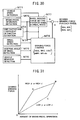
- the grip factor ⁇ was obtained on the basis of the aligning torque, in view of variation of the pneumatic trail of tire.
- a grip factor indicative of a grip level of the tire in its lateral direction can be estimated (in this case " ⁇ m" is used herein), as described hereinafter.
- the road coefficient of friction ⁇ is not included as the parameter.
- the grip factor ⁇ m can be calculated without using the road coefficient of friction ⁇ .
- the grip factor ⁇ m based on the margin of side force for road friction can be employed.
- the relationship between those grip factors ⁇ and ⁇ m will be the one as shown in FIG.21. Therefore, after the grip factor ⁇ was obtained, then it may be converted into the grip factor ⁇ m. On the contrary, after the grip factor ⁇ m was obtained, then it may be converted into the grip factor ⁇ .
- FIG.22 shows an embodiment of the coefficient of friction estimation apparatus, wherein the reaction force torque is calculated by the motor current at units M21-M25, in the same manner as the grip factor estimation apparatus as shown in FIG.7 (In FIG.22, "20" has been added to the number following "M” in each unit of FIG.7) and the frictional torque in the steering system is adjusted, to estimate the aligning torque.
- the wheel factor is obtained through units M26-28 in the same manner as the blocks disclosed in FIGS.17-19.
- the road coefficient of friction ⁇ is obtained at a coefficient of friction estimation unit 30, on the basis of the relationship between the wheel factor and the aligning torque.
- FIG.23 shows an example of the coefficient of friction estimation unit M30, wherein the coefficient of friction is estimated on the basis of the aligning torque estimated at the aligning torque estimation unit M25 and the wheel factor estimated at the wheel factor estimation unit M28.
- the grip factor ⁇ is estimated on the basis of the aligning torque Tsa and the wheel factor Wx, as shown in FIGS.7-14.
- the road coefficient of friction ⁇ is estimated on the basis of the aligning torque and the wheel factor which are obtained when the grip factor has reached a predetermined reference grip factor set at the reference grip factor setting unit M32 for determining the road coefficient of friction to estimate.
- the value indicative of the vehicle behavior obtained when reached the reference grip factor i.e., lateral acceleration or yaw rate, may be used, in stead of the value indicative of the vehicle behavior.
- FIG.24 shows the relationship between the side force Fy and the aligning torque Tsa when the road coefficient of friction ⁇ was lessened, wherein a solid line indicates the characteristic at a high ⁇ and a broken line indicates the characteristic at a low ⁇ .
- the characteristic of the side force to the aligning torque is analog to the road coefficient of friction ⁇ (the characteristic of solid line and broken line in FIG.24). Therefore, the side force Fy or the aligning torque Tsa provided when the grip factor ⁇ obtained by a ratio between the reference aligning torque and the actual aligning torque is identical, directly reflects the road coefficient of friction ⁇ .
- the road coefficient of friction can be estimated on the basis of the value of side force (Fy1, Fy2) or aligning torque (Tsaa1, Tsaa2) obtained when reached the reference grip factor (points J and J') in FIG.24.
- the road coefficient of friction ⁇ can be estimated when the wheel slip angle ⁇ is used as the wheel factor Wx, as will be explained hereinafter with reference to FIG.25.
- the aligning torque Tsa has the nonlinear characteristic to the wheel slip angle ⁇ , as explained before with respect to the estimation of the grip factor. Therefore, the characteristic of the aligning torque to the wheel slip angle is approximated to a linear characteristic as indicated by two-dotted chain line in FIG.25, to estimate the road coefficient of friction ⁇ in a linear zone (0-M zone) to the wheel slip angle ⁇ .
- FIG.26 shows the relationship between the wheel slip angle ⁇ and the aligning torque Tsa, as that in FIG.25, wherein a solid line indicates when the coefficient of friction ⁇ is high and a broken line indicates when the coefficient of friction ⁇ is low.
- the characteristic of the wheel slip angle to the aligning torque is analog to the road coefficient of friction ⁇ (the characteristic of solid line and broken line in FIG.26), similar to that in FIG.24. Therefore, the road coefficient of friction can be estimated on the basis of the value of aligning torque or wheel slip angle ( ⁇ 1, ⁇ 2) obtained when reached the reference grip factor (points S and S' in FIG.26). set in advance.
- the reference grip factor is required to be set in a zone where the relationship between the wheel slip angle and the side force is in a linear characteristic.
- it is required to be estimated in a zone where a certain difference will be caused between the reference aligning torque and the actual aligning torque.
- it is preferable to set the reference grip factor experimentally in such a state that the road coefficient of friction is relatively high as on the dry asphalt road surface, for example.
- the grip factor ⁇ m based on the margin of side force for road friction can be employed.
- the relationship between those grip factors ⁇ and ⁇ m will be the one as shown in FIG.21, after the grip factor ⁇ was obtained, then it may be converted into the grip factor ⁇ m, whereas, after the grip factor ⁇ m was obtained, then it may be converted into the grip factor ⁇ .
- the grip factor and coefficient of friction can be easily estimated, because the steering control system of the present invention is based on the steer-by-wire system.
- the apparatus with the manually operated steering member mechanically connected to the wheels to be steered it is required to detect separately the torque produced by manipulation of the vehicle driver, and the torque produced by the steering assist apparatus (so-called power steering apparatus).
- the torque output from the actuating device (motor) and the reaction torque of the wheel received from the road surface are substantially coincide with each other, the actuating device can be used as a sensor for estimating the road condition.
- the output torque can be obtained by detecting the electric current for actuating the motor MF (MR).
- the current detecting section 23 is required for the control of the motor MF (MR) and a failsafe. Therefore, the road conditions including the grip factor and the coefficient of friction can be estimated easily, so that reduction in cost can be easily achieved.
- FIG.27 shows a setting process of a desired steering angle of the front wheels of the vehicle with the steer-by-wire system.
- a steering operation detection unit M41 the state of steering operation (steering wheel operation angle) by a vehicle driver is detected.
- a steering ratio between a steering wheel operation angle and a steering angle of a wheel is set at a front wheel steering ratio setting unit M45, on the basis of the state of steering operation detected at the steering operation detection unit M41, a vehicle speed detected at a vehicle speed detection unit M42, at least one of the grip factor and road coefficient of friction estimated at a grip factor and coefficient of friction estimation unit M43, wherein the grip factor and the road coefficient of friction are estimated in accordance with the process as described before. Accordingly, a desired value of a steering angle for front wheels is determined on the basis of the steering ratio set at the front wheel steering ratio setting unit M45 and the steering wheel operation angle detected at the steering operation detection unit M41.
- the steering ratio for the front wheels is set at the front wheel steering ratio setting unit M45, so as to be large when the vehicle speed is relatively low, and small when the vehicle speed is relatively high. Therefore, convenience in arranging the steering system on the vehicle will be improved, because the steering angle of the front wheel can be obtained with the steering wheel operated by a small amount, when the vehicle speed is low. On the contrary, the vehicle stability will be improved, because the steering angle of the front wheel is made relatively small in response to the operation of the steering wheel, when the vehicle speed is high. In addition, when the speed of operation of the steering wheel is fast (i.e., steering wheel operation angular velocity is large), the steering ratio for the front wheels is set to be larger than that in a normal steering operation.
- the steering ratio for the front wheels is set on the basis of at least one of the grip factor and the road coefficient of friction.
- the steering ratio for the front wheels is set to be small. Consequently, when the road coefficient of friction is low, or when the grip factor has become low, the steering angle of the front wheel is set to be relatively low in response to operation of the steering wheel, an excessive steering angle will not be give to the front wheels, so that the vehicle stability will be improved.
- a modified steering angle for making the vehicle behavior stable is added to the steering angle, when setting the desired steering angle in response to operation of the steering wheel by a vehicle driver, so that a final desired steering angle ⁇ ft of the front wheel is set at a vehicle stability control unit M48.
- the modified steering angle is determined by a deviation between a reference vehicle state variable obtained on the basis of the amount of steering wheel operation and the vehicle speed at a reference vehicle state variable unit M46, and the actual vehicle state variable calculated by a vehicle state variable calculation unit M47 the result detected by a vehicle behavior detection unit M44, as shown in FIG.27.
- the road coefficient of friction or the grip factor is reflected in the reference vehicle model, to be made more accurate.
- the modified steering angle is determined at the vehicle stability control unit M48
- at least one of the road coefficient of friction and the grip factor is used.
- the threshold level for initiating the vehicle stability control can be set lower than that in a normal vehicle state, and the amount to be controlled on the basis of the deviation of the vehicle state variable can be set lower.
- the desired steering angle of the rear wheels is set according to the blocks as shown in FIG.28, in the same manner as the setting process of the desired steering angle of the front wheels as described before.
- the blocks as shown in FIG.28 is constituted in substantially the same as those disclosed in FIG.27, their explanations are omitted herein, with the last reference letters corresponding to each other omitted in FIG.28.
- a steering ratio between a steering wheel operation angle and a steering angle of rear wheels is set on the basis of at least one of the state of steering operation (steering wheel operation angle), the vehicle speed, and at least one of the grip factor and road coefficient of friction.
- the steering ratio of the rear wheels is controlled to set the steering operation in an opposite phase (in the opposite direction to the steering wheel operation) when the vehicle speed is low, and in a common phase(in the same direction to the steering wheel operation) when the vehicle speed is high, on the basis of at least one of the vehicle speed, and at least one of the grip factor and road coefficient of friction. Consequently, the steer ability is improved when the vehicle speed is low, and the vehicle stability is improved when the vehicle speed is high. As the steering ratio of the rear wheels is set appropriately on the basis of the road coefficient of friction or the grip factor, the vehicle stability can be improved further.
- phase inversion control In the case where the steering wheel is operated fast (i.e., the steering angular velocity is high) in case of an emergency such as presence of obstacles ahead of the vehicle, it is possible to control the steering apparatus to be in an opposite phase for a moment by a so-called phase inversion control, even if the vehicle is running at high speed, to improve the vehicle maneuverability. In the case where the road coefficient of friction is low, or the grip factor is decreased, however, it is preferable to prohibit the phase inversion control, so as to ensure the vehicle stability.
- the desired rear wheel angle is set in accordance with the vehicle state variable. That is, a modified rear wheel angle is determined by a deviation between a reference vehicle state variable obtained on the basis of the amount of operation of the steering wheel and the vehicle speed, and the actual vehicle state variable calculated by a vehicle state variable calculation unit M57. In this case, the road coefficient of friction or the grip factor is reflected in the reference vehicle model, to be made more accurate.
- the modified steering angle is determined at the vehicle stability control unit M58, at least one of the road coefficient of friction and the grip factor is used. For example, when the road coefficient of friction is low, or when the grip factor is decreased, the amount to be controlled on the basis of the deviation of the vehicle state variable can be set lower.
- FIG.29 shows a block diagram for setting a desired steering reaction force at the steering reaction force simulator (SST) as shown in FIGS.3 and 4. It is required for the steering reaction force simulator (SST) to provide the appropriate reaction force, and the information about the reaction force applied to the wheel from the road surface.
- the desired steering reaction force setting unit M67 it is so constituted at the desired steering reaction force setting unit M67 that the desired steering reaction force ⁇ t is set in accordance with at least one of the amount of operation of the steering wheel, steering angle of the wheel, vehicle speed, vehicle state variable, grip factor, and coefficient of friction, to provide a characteristic of steering reaction in accordance with the amount of operation of the vehicle driver.
- the steering operation detection unit M61, steering angle of wheel detection unit M62, grip factor and coefficient of friction estimation unit M63, vehicle speed detection unit M64, vehicle behavior detection unit M65 and the vehicle state variable calculation unit M66 are provide for detecting, estimating, and calculating the factors in the same manner as described before.
- the desired steering reaction force setting unit M67 when the vehicle is running at high speed, the desired steering reaction force is set to be increased, so as to improve the vehicle stability.
- the grip factor and the coefficient of friction is decreased, the desired steering reaction force is set to be different from that in the normal condition, e.g., larger or smaller than the normal steering reaction force, and this state is informed to the vehicle driver.
- FIG.30 shows a block diagram for setting a desired braking force for each wheel.
- a wheel braking force setting unit M77 on the basis of the amount of braking operation, vehicle speed, and at least one of the grip factor and the road coefficient of friction, desired values (Bfrt, Bflt, Brrt, Brlt) of braking force for each wheel are set for the normal mode (i.e., other than the control modes such as ABS, TRC, EBD, VSC, or BA as described before).
- the characteristic of the desired braking force is set in accordance with the amount of operation of the vehicle driver.
- the vehicle speed detection unit M71, brake pedal operation detection unit M72, grip factor and coefficient of friction estimation unit M73, wheel speed detection unit M74, steering angle of wheel detection unit M75 and vehicle behavior detection unit M76 are provide for detecting an estimating the factors in the same manner as described before.
- the braking force applied to the front wheels is set to be larger than that applied to the rear wheels in the braking force distribution control, so as to ensure the vehicle stability.
- the desired wheel braking force for each wheel is set as shown in FIG.31.
- the road coefficient of friction or the grip factor is high, it is set as indicated by a solid line O-A-B in FIG.31.
- the amount of operation of the brake pedal is small, i.e., the vehicle deceleration is small, it is set as indicated by a line segment O-A in FIG.31, to increase the gradient of the desired braking force in response to the amount of operation of the brake pedal.
- the gradient is set to be small as indicated by a line segment A-B, so that controllability of the vehicle deceleration to the amount of operation will be improved.
- the gradient of the desired braking force to the amount of operation of the brake pedal is set to be small, as indicated by a broken line in FIG.31, so that the controllability of the vehicle deceleration will be improved.
- the gradient of the desired braking force to the amount of operation of the brake pedal should be set to be large, as indicated by a line segment C-B in FIG.31, so as to ensure a maximal vehicle speed as a fail safe.
- the desired braking force for each wheel is modified at the braking force control unit M78, wherein the braking force control is performed, such as the anti-skid control (ABS), traction control (TRC), vehicle stability control (VSC), braking force distribution control (EBD), brake assist control (BA) and the like, which are generally known. Therefore, it is so constituted that the threshold values for determining to initiate or terminate those controls, or the controlling amount for those controls are determined on the basis of at least one of the grip factor and the road coefficient of friction.
- ABS anti-skid control
- TRC traction control
- VSC vehicle stability control
- ESD braking force distribution control
- BA brake assist control
- the warning system ALM it is so constitute that if at least one of the estimated grip factor and the road coefficient of friction is decreased to a predetermined threshold level, a warning information is given to the vehicle driver by means of a warning apparatus (as shown in FIG.4) through sound, voice, light, vibration or the like.
- a warning apparatus as shown in FIG.4
- the estimated grip factor is reduced to be less than a predetermined value, for example, it may be so constituted that the engine output shall be reduced, or the braking effect through engine brake shall be increased by a shift down, to brake the vehicle automatically, so that the vehicle speed will be reduced.
- the present invention is directed to a road condition estimation apparatus for estimating a road condition for use in a vehicle having a steering control unit for actuating a device mechanically independent of a manually operated steering member to steer at least a wheel of front and rear wheels.
- the apparatus includes an actuating signal detection unit for detecting an actuating signal for actuating the device of the steering control unit, an aligning torque estimation unit for estimating an aligning torque produced on the wheel on the basis of the actuating signal detected by the actuating signal detection unit, and a vehicle state variable detection unit for detecting a state variable of the vehicle.
- the apparatus further includes a wheel factor estimation unit for estimating at least one of wheel factors including a side force and a slip angle applied to the wheel on the basis of the vehicle state variable, and a grip factor estimation unit for estimating a grip factor of at least a tire of the wheel, in accordance with a relationship between the estimated aligning torque and the estimated wheel factor.
- a wheel factor estimation unit for estimating at least one of wheel factors including a side force and a slip angle applied to the wheel on the basis of the vehicle state variable
- a grip factor estimation unit for estimating a grip factor of at least a tire of the wheel, in accordance with a relationship between the estimated aligning torque and the estimated wheel factor.
Landscapes
- Engineering & Computer Science (AREA)
- Transportation (AREA)
- Mechanical Engineering (AREA)
- Physics & Mathematics (AREA)
- Mathematical Physics (AREA)
- Automation & Control Theory (AREA)
- Chemical & Material Sciences (AREA)
- Combustion & Propulsion (AREA)
- Steering Control In Accordance With Driving Conditions (AREA)
- Control Of Driving Devices And Active Controlling Of Vehicle (AREA)
- Regulating Braking Force (AREA)
Applications Claiming Priority (2)
| Application Number | Priority Date | Filing Date | Title |
|---|---|---|---|
| JP2002298354A JP3940056B2 (ja) | 2002-10-11 | 2002-10-11 | 路面状態推定装置、及び該装置を備えた車両の運動制御装置 |
| JP2002298354 | 2002-10-11 |
Publications (2)
| Publication Number | Publication Date |
|---|---|
| EP1407950A1 true EP1407950A1 (de) | 2004-04-14 |
| EP1407950B1 EP1407950B1 (de) | 2005-03-09 |
Family
ID=32025576
Family Applications (1)
| Application Number | Title | Priority Date | Filing Date |
|---|---|---|---|
| EP03022788A Expired - Lifetime EP1407950B1 (de) | 2002-10-11 | 2003-10-10 | Fahrbahnzustandserfassungsvorrichtung und diese Vorrichtung benutzendes Fahrzeugsteuerungssystem |
Country Status (4)
| Country | Link |
|---|---|
| US (1) | US6952635B2 (de) |
| EP (1) | EP1407950B1 (de) |
| JP (1) | JP3940056B2 (de) |
| DE (1) | DE60300375T2 (de) |
Cited By (9)
| Publication number | Priority date | Publication date | Assignee | Title |
|---|---|---|---|---|
| EP1760451A1 (de) * | 2005-09-01 | 2007-03-07 | GM Global Technology Operations, Inc. | Vorrichtung und Verfahren zur Bestimmung des Reibwerts einer Strassenoberfläche |
| EP1939066A1 (de) * | 2006-12-28 | 2008-07-02 | Nissan Motor Co., Ltd. | Fahrzeuglenksteuerung |
| EP2218618A1 (de) * | 2009-02-16 | 2010-08-18 | Honda Motor Co., Ltd. | Vorrichtung zur Schätzung des Reibungskoeffizienten eines Straßenbelags |
| CN103534563A (zh) * | 2011-04-01 | 2014-01-22 | 斯堪尼亚商用车有限公司 | 车辆重量的估计 |
| EP2813415A1 (de) * | 2013-06-13 | 2014-12-17 | Nissan Motor Manufacturing (UK) Ltd. | Lenkradsteuerungssystem für ein Fahrzeug |
| GB2524060A (en) * | 2014-03-13 | 2015-09-16 | Jaguar Land Rover Ltd | Controller and method |
| CN109969165A (zh) * | 2017-12-27 | 2019-07-05 | 南京理工大学 | 考虑轮胎侧向力贡献的基于目标优化的转矩分配方法 |
| WO2022248159A1 (de) * | 2021-05-28 | 2022-12-01 | Kevin Arnold | Verfahren und vorrichtung zur erlangung von fahrbahnbeschaffenheitsdaten |
| IT202100020948A1 (it) * | 2021-08-03 | 2023-02-03 | Ferrari Spa | Apparato e metodo per stimare un fattore di aderenza di una ruota di un veicolo stradale e relativo veicolo stradale |
Families Citing this family (54)
| Publication number | Priority date | Publication date | Assignee | Title |
|---|---|---|---|---|
| JP3868848B2 (ja) * | 2002-05-23 | 2007-01-17 | 三菱電機株式会社 | 車両状態検出装置 |
| JP3964771B2 (ja) * | 2002-10-11 | 2007-08-22 | 株式会社豊田中央研究所 | 路面状態推定装置、及び該装置を備えた車両の運動制御装置 |
| JP4213994B2 (ja) * | 2003-05-28 | 2009-01-28 | 株式会社豊田中央研究所 | タイヤグリップ度推定装置及び方法、走行状態制御方法 |
| JP4024187B2 (ja) * | 2003-07-22 | 2007-12-19 | アイシン精機株式会社 | 荷重移動状態推定装置及びローリング状態推定装置 |
| JP4213545B2 (ja) * | 2003-09-05 | 2009-01-21 | 株式会社ジェイテクト | 車輪のグリップ度推定装置、及び該装置を備えた車両の運動制御装置 |
| US7502675B2 (en) * | 2004-04-01 | 2009-03-10 | Delphi Technologies, Inc. | Feedforward control of motor vehicle roll angle |
| JP4425687B2 (ja) * | 2004-04-08 | 2010-03-03 | 本田技研工業株式会社 | 操舵装置 |
| US7349778B2 (en) * | 2004-06-09 | 2008-03-25 | General Motors Corporation | Real-time vehicle dynamics estimation system |
| EP1627790B1 (de) * | 2004-08-19 | 2008-02-20 | HONDA MOTOR CO., Ltd. | Verfahren zur Bestimmung des Reibwerts einer Strassenoberfläche und des Rutschwinkels eines Kraftfahrzeugs |
| JP4421426B2 (ja) * | 2004-08-31 | 2010-02-24 | 本田技研工業株式会社 | 操舵装置 |
| US20060253243A1 (en) * | 2005-05-06 | 2006-11-09 | Jacob Svendenius | System and method for tire/road friction estimation |
| US7715964B1 (en) * | 2005-05-10 | 2010-05-11 | Trimble Navigation, Ltd. | Very low speed vehicle control algorithm operating in the spatial domain |
| US7734418B2 (en) * | 2005-06-28 | 2010-06-08 | Honda Motor Co., Ltd. | Vehicle operation assisting system |
| US8335625B2 (en) * | 2005-09-06 | 2012-12-18 | Nissan Motor Co., Ltd. | Slip control device and method for a vehicle |
| JP4887721B2 (ja) * | 2005-10-14 | 2012-02-29 | 日産自動車株式会社 | 車両走行状態推定装置 |
| ITBO20060424A1 (it) * | 2006-05-31 | 2007-12-01 | Ferrari Spa | Sistema di sterzatura per una automobile |
| JP2008018832A (ja) * | 2006-07-12 | 2008-01-31 | Fuji Heavy Ind Ltd | 車両運動制御装置 |
| DE102007027040A1 (de) * | 2006-07-13 | 2008-01-24 | Tedrive Holding Bv | Sicherheitsverfahren eines Lenksystems |
| JP2008057577A (ja) * | 2006-08-29 | 2008-03-13 | Toyota Motor Corp | 車両の制御装置 |
| US7624836B2 (en) * | 2006-10-30 | 2009-12-01 | Caterpillar Inc. | Steering system having multiple strategies and variable deadzone |
| EP1995150A3 (de) * | 2007-05-25 | 2009-05-06 | NSK Ltd. | Elektrische Servolenkung |
| JP5336052B2 (ja) * | 2007-05-28 | 2013-11-06 | 株式会社デンソー | クルーズ制御装置、プログラム、及び目標車速の設定方法 |
| US8051687B2 (en) * | 2007-10-31 | 2011-11-08 | GM Global Technology Operations LLC | Traction steer detection and compensation |
| JP4924378B2 (ja) * | 2007-11-19 | 2012-04-25 | トヨタ自動車株式会社 | 車輌の走行制御装置 |
| DE102007000995A1 (de) * | 2007-11-28 | 2009-06-04 | Zf Lenksysteme Gmbh | Verfahren zum Betrieb einer Überlagerungslenkung für ein Kraftfahrzeug |
| GB0807935D0 (en) * | 2008-05-01 | 2008-06-11 | Trw Ltd | Improvements relating to steering systems |
| JP2010052657A (ja) * | 2008-08-29 | 2010-03-11 | Mitsubishi Electric Corp | 車両制御装置 |
| JP5228799B2 (ja) * | 2008-10-29 | 2013-07-03 | 日産自動車株式会社 | 車両接地面摩擦状態推定装置及びその方法 |
| JP5158211B2 (ja) * | 2008-12-26 | 2013-03-06 | トヨタ自動車株式会社 | パワーステアリング装置 |
| JP5097165B2 (ja) * | 2009-05-22 | 2012-12-12 | 三菱電機株式会社 | 車両制御装置 |
| JP5271209B2 (ja) * | 2009-09-08 | 2013-08-21 | 富士重工業株式会社 | 路面摩擦係数推定装置 |
| GB2473436B (en) * | 2009-09-09 | 2016-02-17 | Gm Global Tech Operations Inc | Method and apparatus for road surface friction estimation based on the self aligning torque |
| JP2011057214A (ja) * | 2010-10-01 | 2011-03-24 | Mitsubishi Electric Corp | 車両制御装置 |
| JP2011057215A (ja) * | 2010-10-01 | 2011-03-24 | Mitsubishi Electric Corp | 車両制御装置 |
| JP5289408B2 (ja) * | 2010-10-01 | 2013-09-11 | 三菱電機株式会社 | 車両制御装置 |
| JP5826680B2 (ja) * | 2012-03-09 | 2015-12-02 | Ntn株式会社 | ステアバイワイヤ式操舵機構の制御装置 |
| CN104583038A (zh) * | 2012-08-30 | 2015-04-29 | 丰田自动车株式会社 | 车辆的控制装置 |
| JP5751241B2 (ja) * | 2012-11-13 | 2015-07-22 | 株式会社豊田中央研究所 | 車両操舵装置及びプログラム |
| JP2014166805A (ja) * | 2013-02-28 | 2014-09-11 | Jtekt Corp | 電動パワーステアリング装置 |
| US8983749B1 (en) * | 2013-10-24 | 2015-03-17 | The Goodyear Tire & Rubber Company | Road friction estimation system and method |
| CN103707884A (zh) * | 2013-12-26 | 2014-04-09 | 广东工业大学 | 一种赛车稳定性控制装置及控制方法 |
| US9663115B2 (en) * | 2015-10-09 | 2017-05-30 | The Goodyear Tire & Rubber Company | Method for estimating tire forces from CAN-bus accessible sensor inputs |
| ITUB20159358A1 (it) * | 2015-12-22 | 2017-06-22 | Faiveley Transport Italia Spa | Procedimento per il controllo e il recupero dell'aderenza delle ruote di un assile controllato di un veicolo ferroviario. |
| DE102017219879B4 (de) | 2017-11-08 | 2023-08-24 | Audi Ag | Verfahren zur Bestimmung des Reibwerts einer Fahrbahnoberfläche |
| JP6607532B2 (ja) * | 2017-12-27 | 2019-11-20 | マツダ株式会社 | 車両の挙動制御装置 |
| JP2019131013A (ja) * | 2018-01-30 | 2019-08-08 | 株式会社ジェイテクト | 操舵制御装置 |
| JP6910973B2 (ja) * | 2018-02-02 | 2021-07-28 | 日立Astemo株式会社 | 車両制御装置及びその制御方法並びに車両制御システム |
| JP7099056B2 (ja) * | 2018-06-01 | 2022-07-12 | 株式会社ジェイテクト | 操舵制御装置 |
| JP7243045B2 (ja) * | 2018-06-01 | 2023-03-22 | 株式会社ジェイテクト | 操舵制御装置 |
| JP7087688B2 (ja) * | 2018-06-01 | 2022-06-21 | 株式会社ジェイテクト | 操舵制御装置 |
| US11097769B2 (en) * | 2018-06-01 | 2021-08-24 | Jtekt Corporation | Steering control device |
| JP7155616B2 (ja) * | 2018-06-01 | 2022-10-19 | 株式会社ジェイテクト | 操舵制御装置 |
| JP7488632B2 (ja) * | 2019-02-14 | 2024-05-22 | 日立Astemo株式会社 | 操舵制御装置 |
| DE102019121969A1 (de) * | 2019-08-15 | 2021-02-18 | Wabco Europe Bvba | Verfahren zum Steuern eines Fahrzeuges bei einer Bremsung mit seitenweise unterschiedlich wirkenden Bremskräften, Steuersystem und Fahrzeug |
Citations (4)
| Publication number | Priority date | Publication date | Assignee | Title |
|---|---|---|---|---|
| EP0716948A2 (de) * | 1994-12-14 | 1996-06-19 | Toyota Jidosha Kabushiki Kaisha | Vorrichtung zum Einschätzen des dynamischen Verhaltens eines Kraftfahrzeugs |
| US20010003810A1 (en) * | 1997-07-09 | 2001-06-14 | Tomoyuki Shinmura | Collision avoiding system for vehicles |
| US20020011093A1 (en) * | 2000-06-29 | 2002-01-31 | Fuji Jukogyo Kabushiki Kaisha | Road friction coefficient estimating apparatus and vehicle equipped with road friction coefficient estimating apparatus |
| US6349789B1 (en) * | 1997-11-12 | 2002-02-26 | Koyo Seiko Co., Ltd. | Steering device for vehicles |
Family Cites Families (14)
| Publication number | Priority date | Publication date | Assignee | Title |
|---|---|---|---|---|
| DE3545715A1 (de) | 1985-12-21 | 1987-07-02 | Daimler Benz Ag | Einrichtung zur vortriebsregelung an kraftfahrzeugen |
| US4882693A (en) | 1987-12-28 | 1989-11-21 | Ford Motor Company | Automotive system for dynamically determining road adhesion |
| DE3922528C1 (en) | 1989-07-08 | 1990-07-19 | Daimler-Benz Aktiengesellschaft, 7000 Stuttgart, De | Detecting limit of ground adhesion of vehicle tyres - measuring steering arm torque comparing measured valve with reference and comparing difference to threshold value |
| JP2600986B2 (ja) * | 1990-07-06 | 1997-04-16 | 三菱自動車工業株式会社 | 後輪の操舵制御方法 |
| US5259476A (en) * | 1991-04-26 | 1993-11-09 | Fuji Jukogyo Kabushiki Kaisha | Torque distribution control system for a four-wheel drive motor vehicle |
| DE4123235C2 (de) | 1991-07-13 | 1997-04-03 | Daimler Benz Ag | Verfahren zur Verhinderung von Instabilitäten des Fahrverhaltens eines Fahrzeuges |
| JP3561955B2 (ja) | 1994-06-14 | 2004-09-08 | アイシン精機株式会社 | 操舵制御装置の異常検出装置 |
| JPH09109866A (ja) * | 1995-10-19 | 1997-04-28 | Fuji Heavy Ind Ltd | 車両運動制御装置 |
| JP4015759B2 (ja) | 1997-08-01 | 2007-11-28 | 本田技研工業株式会社 | 車両用可変舵角比操舵装置 |
| JP3850530B2 (ja) * | 1997-10-21 | 2006-11-29 | 富士重工業株式会社 | 車両運動制御装置 |
| JP4037506B2 (ja) * | 1998-03-12 | 2008-01-23 | 富士重工業株式会社 | 車両運動制御装置 |
| JP3497746B2 (ja) * | 1998-10-26 | 2004-02-16 | 本田技研工業株式会社 | 電動パワーステアリング装置 |
| JP4355874B2 (ja) | 1999-11-02 | 2009-11-04 | 株式会社ジェイテクト | 車両用操舵装置 |
| JP4019813B2 (ja) * | 2001-07-12 | 2007-12-12 | 株式会社豊田中央研究所 | 物理量推定装置、路面摩擦状態推定装置、操舵角中立点推定装置、及び空気圧低下推定装置 |
-
2002
- 2002-10-11 JP JP2002298354A patent/JP3940056B2/ja not_active Expired - Lifetime
-
2003
- 2003-10-10 DE DE60300375T patent/DE60300375T2/de not_active Expired - Lifetime
- 2003-10-10 US US10/682,406 patent/US6952635B2/en not_active Expired - Lifetime
- 2003-10-10 EP EP03022788A patent/EP1407950B1/de not_active Expired - Lifetime
Patent Citations (4)
| Publication number | Priority date | Publication date | Assignee | Title |
|---|---|---|---|---|
| EP0716948A2 (de) * | 1994-12-14 | 1996-06-19 | Toyota Jidosha Kabushiki Kaisha | Vorrichtung zum Einschätzen des dynamischen Verhaltens eines Kraftfahrzeugs |
| US20010003810A1 (en) * | 1997-07-09 | 2001-06-14 | Tomoyuki Shinmura | Collision avoiding system for vehicles |
| US6349789B1 (en) * | 1997-11-12 | 2002-02-26 | Koyo Seiko Co., Ltd. | Steering device for vehicles |
| US20020011093A1 (en) * | 2000-06-29 | 2002-01-31 | Fuji Jukogyo Kabushiki Kaisha | Road friction coefficient estimating apparatus and vehicle equipped with road friction coefficient estimating apparatus |
Cited By (15)
| Publication number | Priority date | Publication date | Assignee | Title |
|---|---|---|---|---|
| EP1760451A1 (de) * | 2005-09-01 | 2007-03-07 | GM Global Technology Operations, Inc. | Vorrichtung und Verfahren zur Bestimmung des Reibwerts einer Strassenoberfläche |
| EP1939066A1 (de) * | 2006-12-28 | 2008-07-02 | Nissan Motor Co., Ltd. | Fahrzeuglenksteuerung |
| US8010254B2 (en) | 2006-12-28 | 2011-08-30 | Nissan Motor Co., Ltd. | Vehicle steering controller |
| US9221439B2 (en) | 2009-02-16 | 2015-12-29 | Honda Motor Co., Ltd. | Road surface frictional coefficient estimating apparatus |
| EP2218618A1 (de) * | 2009-02-16 | 2010-08-18 | Honda Motor Co., Ltd. | Vorrichtung zur Schätzung des Reibungskoeffizienten eines Straßenbelags |
| CN103534563A (zh) * | 2011-04-01 | 2014-01-22 | 斯堪尼亚商用车有限公司 | 车辆重量的估计 |
| EP2813415A1 (de) * | 2013-06-13 | 2014-12-17 | Nissan Motor Manufacturing (UK) Ltd. | Lenkradsteuerungssystem für ein Fahrzeug |
| GB2524060A (en) * | 2014-03-13 | 2015-09-16 | Jaguar Land Rover Ltd | Controller and method |
| GB2524060B (en) * | 2014-03-13 | 2016-12-14 | Jaguar Land Rover Ltd | Controller and method |
| US10196064B2 (en) | 2014-03-13 | 2019-02-05 | Jaguar Land Rover Limited | Controller and method for controlling a motor vehicle |
| CN109969165A (zh) * | 2017-12-27 | 2019-07-05 | 南京理工大学 | 考虑轮胎侧向力贡献的基于目标优化的转矩分配方法 |
| CN109969165B (zh) * | 2017-12-27 | 2020-10-02 | 南京理工大学 | 考虑轮胎侧向力贡献的基于目标优化的转矩分配方法 |
| WO2022248159A1 (de) * | 2021-05-28 | 2022-12-01 | Kevin Arnold | Verfahren und vorrichtung zur erlangung von fahrbahnbeschaffenheitsdaten |
| IT202100020948A1 (it) * | 2021-08-03 | 2023-02-03 | Ferrari Spa | Apparato e metodo per stimare un fattore di aderenza di una ruota di un veicolo stradale e relativo veicolo stradale |
| EP4129778A1 (de) * | 2021-08-03 | 2023-02-08 | FERRARI S.p.A. | Vorrichtung und verfahren zum schätzen eines haftungsfaktors eines rades eines strassenfahrzeugs und entsprechendes strassenfahrzeug |
Also Published As
| Publication number | Publication date |
|---|---|
| DE60300375T2 (de) | 2006-02-09 |
| DE60300375D1 (de) | 2005-04-14 |
| US20040148077A1 (en) | 2004-07-29 |
| JP3940056B2 (ja) | 2007-07-04 |
| EP1407950B1 (de) | 2005-03-09 |
| JP2004130964A (ja) | 2004-04-30 |
| US6952635B2 (en) | 2005-10-04 |
Similar Documents
| Publication | Publication Date | Title |
|---|---|---|
| EP1407950B1 (de) | Fahrbahnzustandserfassungsvorrichtung und diese Vorrichtung benutzendes Fahrzeugsteuerungssystem | |
| EP1407949B1 (de) | Fahrbahnzustandserfassungsvorrichtung und diese Vorrichtung benutzendes Fahrzeugsteuerungssystem | |
| EP1357008B1 (de) | Vorrichtung zur Regelung der Fahrzeugbewegung | |
| EP1357007B1 (de) | Vorrichtung zur Schätzung des Haftungsfaktors eines Fahrzeugrades | |
| EP1512598B1 (de) | Vorrichtung zur Schätzung des Haftungsfaktors eines Fahrzeugrades und Vorrichtung zur Regelung der Fahrzeugbewegung | |
| Van Zanten | Evolution of electronic control systems for improving the vehicle dynamic behavior | |
| JP4063576B2 (ja) | 車輪のグリップ度推定装置、及び該装置を備えた車両の運動制御装置 | |
| JP4042277B2 (ja) | 車体横すべり角推定装置 | |
| US20050096830A1 (en) | Integrated control apparatus for vehicle | |
| US6792343B2 (en) | Antiskid braking control system | |
| US20060041366A1 (en) | Motion control device of vehicle | |
| Yasui et al. | Estimation of lateral grip margin based on self-aligning torque for vehicle dynamics enhancement | |
| US7191048B2 (en) | Vehicle motion control apparatus | |
| KR101152296B1 (ko) | 차량 안전성 제어시스템 | |
| CN107161126B (zh) | 用于在abs制动期间控制车辆的相反转向的方法 | |
| JP4678311B2 (ja) | 車両の進行方向判定装置 | |
| JP4284210B2 (ja) | 車両の操舵制御装置 | |
| JP4872386B2 (ja) | 車両の運動制御装置 | |
| JP2006117154A (ja) | 車両の運動制御装置 |
Legal Events
| Date | Code | Title | Description |
|---|---|---|---|
| PUAI | Public reference made under article 153(3) epc to a published international application that has entered the european phase |
Free format text: ORIGINAL CODE: 0009012 |
|
| AK | Designated contracting states |
Kind code of ref document: A1 Designated state(s): AT BE BG CH CY CZ DE DK EE ES FI FR GB GR HU IE IT LI LU MC NL PT RO SE SI SK TR |
|
| AX | Request for extension of the european patent |
Extension state: AL LT LV MK |
|
| 17P | Request for examination filed |
Effective date: 20040322 |
|
| GRAP | Despatch of communication of intention to grant a patent |
Free format text: ORIGINAL CODE: EPIDOSNIGR1 |
|
| GRAS | Grant fee paid |
Free format text: ORIGINAL CODE: EPIDOSNIGR3 |
|
| RAP1 | Party data changed (applicant data changed or rights of an application transferred) |
Owner name: TOYODA KOKI KABUSHIKI KAISHA Owner name: AISIN SEIKI KABUSHIKI KAISHA |
|
| RAP1 | Party data changed (applicant data changed or rights of an application transferred) |
Owner name: AISIN SEIKI KABUSHIKI KAISHA Owner name: ADVICS CO., LTD. Owner name: TOYODA KOKI KABUSHIKI KAISHA |
|
| AKX | Designation fees paid |
Designated state(s): DE FR GB |
|
| GRAA | (expected) grant |
Free format text: ORIGINAL CODE: 0009210 |
|
| AK | Designated contracting states |
Kind code of ref document: B1 Designated state(s): DE FR GB |
|
| RAP1 | Party data changed (applicant data changed or rights of an application transferred) |
Owner name: ADVICS CO., LTD. Owner name: AISIN SEIKI KABUSHIKI KAISHA Owner name: TOYODA KOKI KABUSHIKI KAISHA |
|
| REG | Reference to a national code |
Ref country code: GB Ref legal event code: FG4D |
|
| REG | Reference to a national code |
Ref country code: IE Ref legal event code: FG4D |
|
| REF | Corresponds to: |
Ref document number: 60300375 Country of ref document: DE Date of ref document: 20050414 Kind code of ref document: P |
|
| ET | Fr: translation filed | ||
| PLBE | No opposition filed within time limit |
Free format text: ORIGINAL CODE: 0009261 |
|
| STAA | Information on the status of an ep patent application or granted ep patent |
Free format text: STATUS: NO OPPOSITION FILED WITHIN TIME LIMIT |
|
| 26N | No opposition filed |
Effective date: 20051212 |
|
| REG | Reference to a national code |
Ref country code: FR Ref legal event code: PLFP Year of fee payment: 14 |
|
| REG | Reference to a national code |
Ref country code: FR Ref legal event code: PLFP Year of fee payment: 15 |
|
| REG | Reference to a national code |
Ref country code: FR Ref legal event code: PLFP Year of fee payment: 16 |
|
| PGFP | Annual fee paid to national office [announced via postgrant information from national office to epo] |
Ref country code: GB Payment date: 20181010 Year of fee payment: 16 |
|
| GBPC | Gb: european patent ceased through non-payment of renewal fee |
Effective date: 20191010 |
|
| PG25 | Lapsed in a contracting state [announced via postgrant information from national office to epo] |
Ref country code: GB Free format text: LAPSE BECAUSE OF NON-PAYMENT OF DUE FEES Effective date: 20191010 |
|
| PGFP | Annual fee paid to national office [announced via postgrant information from national office to epo] |
Ref country code: FR Payment date: 20220908 Year of fee payment: 20 |
|
| PGFP | Annual fee paid to national office [announced via postgrant information from national office to epo] |
Ref country code: DE Payment date: 20220621 Year of fee payment: 20 |
|
| REG | Reference to a national code |
Ref country code: DE Ref legal event code: R071 Ref document number: 60300375 Country of ref document: DE |