EP1398416B1 - Verlegeverfahren für eine zerlegbare Brücke - Google Patents
Verlegeverfahren für eine zerlegbare Brücke Download PDFInfo
- Publication number
- EP1398416B1 EP1398416B1 EP03015414A EP03015414A EP1398416B1 EP 1398416 B1 EP1398416 B1 EP 1398416B1 EP 03015414 A EP03015414 A EP 03015414A EP 03015414 A EP03015414 A EP 03015414A EP 1398416 B1 EP1398416 B1 EP 1398416B1
- Authority
- EP
- European Patent Office
- Prior art keywords
- bridge
- laying
- rollers
- girder
- bridge girder
- Prior art date
- Legal status (The legal status is an assumption and is not a legal conclusion. Google has not performed a legal analysis and makes no representation as to the accuracy of the status listed.)
- Expired - Lifetime
Links
- 238000000034 method Methods 0.000 title claims abstract description 18
- 239000000969 carrier Substances 0.000 claims description 5
- 238000010276 construction Methods 0.000 description 1
- 230000008878 coupling Effects 0.000 description 1
- 238000010168 coupling process Methods 0.000 description 1
- 238000005859 coupling reaction Methods 0.000 description 1
- 230000010354 integration Effects 0.000 description 1
- 239000007787 solid Substances 0.000 description 1
- 239000013585 weight reducing agent Substances 0.000 description 1
Images

Classifications
-
- E—FIXED CONSTRUCTIONS
- E01—CONSTRUCTION OF ROADS, RAILWAYS, OR BRIDGES
- E01D—CONSTRUCTION OF BRIDGES, ELEVATED ROADWAYS OR VIADUCTS; ASSEMBLY OF BRIDGES
- E01D15/00—Movable or portable bridges; Floating bridges
- E01D15/12—Portable or sectional bridges
- E01D15/133—Portable or sectional bridges built-up from readily separable standardised sections or elements, e.g. Bailey bridges
-
- E—FIXED CONSTRUCTIONS
- E01—CONSTRUCTION OF ROADS, RAILWAYS, OR BRIDGES
- E01D—CONSTRUCTION OF BRIDGES, ELEVATED ROADWAYS OR VIADUCTS; ASSEMBLY OF BRIDGES
- E01D19/00—Structural or constructional details of bridges
- E01D19/005—Piers, trestles, bearings, expansion joints or parapets specially adapted for portable or sectional bridges
Definitions
- the invention relates to a laying method according to the preamble of claim 1 for a collapsible bridge, i. a transportable bridge for mobile use.
- the structures of portable bridges must be as light as possible when laying the bridge. Especially in the free stem, the weight of the bridge girder to be installed has a very strong effect on the forces to be controlled and on the counterweight for the required stability and thus on the overall weight of the bridge system to be transported.
- the rails leaving the rail of the laying beam are removed with the associated roller carrier from the bridge support to be laid during the laying process and at another location of the bridge support, which is currently located before entering the rail of the laying beam, again.
- the invention combines the advantages of the two described laying methods according to the prior art, in which the rollers are mounted with their support structure only as long as the support to be laid, as required by the laying process.
- the bridge girder to be laid can be designed, in particular, as a truss girder or as a solid or box girder.
- the invention makes it possible to lay a bridge girder without the straps of the carrier being loaded by roller pressing.
- the invention makes it possible to realize a lighter, simpler and less expensive bridge carrier, since both the roles and their integration into the structure accounts.
- the invention allows in the free stem a lower counterweight to the realization of the required stability. This further reduces the transport weight of the system beyond the weight reduction of the bridge girder.
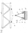
- Fig. 1 is the example of a bridge track carrier 3, which is designed as a truss girder 3 with triangular cross-section, the flow of the laying process.
- a laying bar V with a rail attached thereto for displacing the carrier 3 is positioned.
- Reference numeral VS denotes a support on the laying beam V.
- each roller carrier carries exactly two roles - see Fig. 3 mounted in the lower node of the support framework.
- the middle two rollers are located in the rail of the laying beam V, which encloses the rollers R U-shaped.
- the large arrow indicates that in this state of construction, the front roller R, which has already left the laying beam V, is removed and must be mounted on the truss node of the carrier 3 behind the laying beam V.
- FIG. 1 shows essentially the same situation, except that here another bridge section 33 has been coupled and the bridge carrier has already moved a role sharing on the obstacle, so that here too the roller carrier with roller R, the laying beam V last left, dismantled and rear, before entry into the laying beam, can be re-assembled.
- this process is repeated at the bridge, which has already been pushed far over the obstacle.
- FIG. 2 shows a bridge track carrier 3 with two roller carriers RT mounted in the lower truss node with associated rollers R.
- FIG. 3 shows the roller carrier RT, which surrounds the lower flange U of the bridge girder 3 and thus introduces forces upward as contact forces in the lower flange U.
- the side flaps L enclose the truss node.
- the laterally mounted rollers R are enclosed by the rail of the laying beam V, which receives the roller forces in all directions.
Landscapes
- Engineering & Computer Science (AREA)
- Architecture (AREA)
- Civil Engineering (AREA)
- Structural Engineering (AREA)
- Bridges Or Land Bridges (AREA)
- Automobile Manufacture Line, Endless Track Vehicle, Trailer (AREA)
- Forklifts And Lifting Vehicles (AREA)
- Mechanical Coupling Of Light Guides (AREA)
Description
- Die Erfindung betrifft ein Verlegeverfahren gemäß Oberbegriff des Patentanspruch 1 für eine zerlegbare Brücke, d.h. einer transportablen Brücke für den mobilen Einsatz.
- Die Strukturen transportabler Brücken müssen beim Verlegen der Brücke möglichst leicht sein. Vor allem im freien Vorbau wirkt sich das Gewicht des zu verlegenden Brückenträgers sehr stark auf die zu beherrschenden Kräfte und auf das Gegengewicht für die erforderliche Standsicherheit aus und somit insgesamt auf das zu transportierende Gewicht des Brückensystems.
- Es gibt zwei prinzipielle Methoden, einen Träger über ein Hindernis zu verlegen (beide sind in der US 4,920,595 beschrieben):
- 1. Rollen am Ufer (montiert am Verlegebalken), Schiene am Brückenträger.
Vorteil: kein Rollengewicht beim Verlegen der Brücke.
Nachteil: Schiene mit hoher Rollenpressung ist zugleich hochbelasteter Ober- und Untergurt beim Verlegen und beim Befahren der Brücke. - 2. Rollen am Brückenträger, Schiene am Ufer (montiert am Verlegebalken).
Vorteil: Hochbelastete Gurte werden nicht durch Rollenpressung beaufschlagt.
Nachteil: Das Rollengewicht muss mitverlegt werden. - Aufgabe der Erfindung ist es, ein Verlegeverfahren zu schaffen, dass die Vorteile der beiden bekannten Verlegeverfahren aufweist, jedoch ohne die mit diesen Verfahren verbundenen Nachteilen.
- Diese Aufgabe wird mit dem Verfahren nach Patentanspruch 1 gelöst. Ein für das erfindungsgemäße Verfahren geeigneter Brückenträger ist Gegenstand weiterer Patentansprüche.
- Erfindungsgemäß werden während des Verlegevorgangs die die Schiene des Verlegebalkens verlassenden Rollen mit zugehörigem Rollenträger von dem zu verlegenden Brückenträger abgenommen und an einer andereren Stelle des Brükkenträgers, die sich momentan vor dem Eintritt in die Schiene des Verlegebalkens befindet, wieder angebracht.
- Die Erfindung kombiniert die Vorteile der beiden beschriebenen Verlegeverfahren gemäß Stand der Technik, in dem die Rollen mit ihrer Tragstruktur nur so lange am zu verlegenden Träger montiert sind, wie es der Verlegevorgang erfordert.
- Als zu verlegende Brückenträger kommen sowohl Brückenspurträger, Vorbauträger als auch sonstige Brückenträger in Frage.
- Der zu verlegende Brückenträger kann insbesondere als Fachwerkträger oder als Vollwand- oder Kastenträger ausgebildet sein.
- Die Erfindung erlaubt es, einen Brückenträger zu verlegen, ohne ihn durch zusätzliche Gewichte (Rollen sowie Bauteile zur Einbindung der Rollen in die Struktur des Brückenträgers) zu belasten, die nur für den Verlegevorgang erforderlich sind.
- Die Erfindung erlaubt es, einen Brückenträger zu verlegen, ohne dass die Gurte des Trägers durch Rollenpressung belastet werden.
- Die Erfindung erlaubt es, einen leichteren, einfacheren und kostengünstigeren Brückenträger zu realisieren, da sowohl die Rollen als auch deren Einbindung in die Struktur entfallen.
- Die Erfindung erlaubt im freien Vorbau ein geringeres Gegengewicht zur Realisierung der erforderlichen Standsicherheit. Dadurch wird das Transportgewicht des Systems über die Gewichtsreduzierung des Brückenträgers hinaus weiter reduziert.
- Die Erfindung wird anhand von Ausführungsbeispielen unter Bezugnahme auf Figuren näher erläutert. Es zeigen:
- Fig. 1
- den Ablauf des erfindungsgemäßen Verfahrens in mehreren Momentaufnahmen;
- Fig. 2
- einen Brückenträger mit daran angeordneten Rollen;
- Fig. 3
- einen Verlegebalken mit darauf befindlichem Brückenträger während des Verlegvorgangs.
- In Fig. 1 ist am Beispiel eines Brückenspurträgers 3, der als Fachwerkträger 3 mit dreieckförmigen Querschnitt ausgebildet ist, der Ablauf des Verlegeverfahrens dargestellt.
- Vor dem zu überbrückenden Hindernis ist ein Verlegebalken V mit daran angebrachter Schiene zum Verschieben des Trägers 3 positioniert. Bezugsziffer VS bezeichnet eine Stütze am Verlegebalken V.
- Im ersten Bild sind bereits zwei Abschnitte 31,32 des Trägers 3 miteinander gekuppelt (Kuppelstellen 11) und vier Rollenträger mit zugehörigen Rollen R (in dieser Ausführung trägt jeder Rollenträger genau zwei Rollen - siehe Fig. 3) in den unteren Knoten des Trägerfachwerks montiert. Die mittleren beiden Rollen befinden sich in der Schiene des Verlegebalkens V, welche die Rollen R U-förmig umschließt. Der große Pfeil zeigt an, dass bei diesem Bauzustand die vordere Rolle R, die den Verlegebalken V bereits verlassen hat, abmontiert wird und an dem Fachwerkknoten des Trägers 3 hinter dem Verlegebalken V montiert werden muss.
- Das nächste Bild in Fig. 1 zeigt im wesentlichen die gleiche Situation, nur dass hier ein weiterer Brückenabschnitt 33 angekuppelt wurde und der Brückenträger bereits eine Rollenteilung weiter über das Hindernis verschoben wurde, so dass auch hier der Rollenträger mit Rolle R, der den Verlegebalken V zuletzt verlassen hat, abmontiert und hinten, vor Eintritt in den Verlegebalken, wieder montiert werden kann.
- Im dritten Bild wiederholt sich dieser Vorgang bei der bereits weit über das Hindernis geschobenen Brücke.
- Die detaillierte Skizze gemäß Fig. 2 zeigt einen Brückenspurträger 3 mit zwei in den unteren Fachwerkknoten montierten Rollenträgern RT mit zugehörigen Rollen R.
- Das Schnittbild gemäß Fig. 3 zeigt den Rollenträger RT, der den Untergurt U des Brückenträgers 3 umschließt und so Kräfte nach oben als Kontaktkräfte in den Untergurt U einleitet. Die seitlichen Laschen L umschließen den Fachwerkknoten. Durch zwei Bolzen B, die jeweils durch die beiden seitlichen Laschen L gesteckt werden, wird der Kraftschluss für nach unten gerichtete Kräfte hergestellt, die auch wieder als Kontaktkräfte direkt in den Fachwerkknoten des Trägers 3 eingeleitet werden.
- Die seitlich angebrachten Rollen R werden durch die Schiene des Verlegebalkens V umschlossen, die die Rollenkräfte in allen Richtungen aufnimmt.
Claims (4)
- Vertegeverfahren für eine zerlegbare Brücke, wobei die Brückenträger (3) über einen vor dem zu überbrückenden Hindernis positionierten Verlegebalken (V) über das Hindernis geschoben werden, wobei an den Brückenträgern Rollen (R) und diese tragenden Rollenträger (RT) befestigt sind, wobei die Rollen (R) in am Verlegebalken (V) angeordneten Schienen laufen, dadurch gekennzeichnet, dass während des Verlegevorgangs die die Schiene des Verlegebalkens verlassenden Rollen (R) mit zugehörigem Rollenträger (RT) vom Brückenträger (3) abgenommen werden und an einer andereren Stelle des Brückenträgers (3), die sich momentan vor dem Eintritt in die Schiene des Verlegebalkens (V) befindet, wieder angebracht werden.
- Brückenträger (3) zur Verlegung einer Brücke nach dem Verlegeverfahren gemäß Anspruch 1, wobei an der Unterseite des Brückenträgers Rollen (R) sowie diese tragenden Rollenträger (RT) befestigt sind, wobei die Rollen (R) in an einem Verlegebalken (V) angeordneten Schienen laufbar sind, dadurch gekennzeichnet, dass die Rollen (R) sowie diese tragenden Rollenträger derart wiederlösbar befestigt sind, dass während des Verlegevorgangs die die Schiene des Verlegebalkens verlassenden Rollen (R) mit zugehörigem Rollenträger (RT) vom Brückenträger (3) abnehmebar und an einer anderen Stelle des Brückenträgers (3), die sich momentan vor dem Eintritt in die Schiene des Verlegebalkens (V) befindet, wieder anbringbar sind.
- Brückenträger (3) nach Anspruch 2, dadurch gekennzeichnet, dass er als Fachwerkträger ausgebildet ist.
- Brückenträger nach Anspruch 2, dadurch gekennzeichnet, dass er als Vollwandträger oder Kastenträger ausgebildet ist.
Applications Claiming Priority (2)
| Application Number | Priority Date | Filing Date | Title |
|---|---|---|---|
| DE10242836A DE10242836C1 (de) | 2002-09-14 | 2002-09-14 | Verlegeverfahren für eine zerlegbare Brücke |
| DE10242836 | 2002-09-14 |
Publications (3)
| Publication Number | Publication Date |
|---|---|
| EP1398416A2 EP1398416A2 (de) | 2004-03-17 |
| EP1398416A3 EP1398416A3 (de) | 2004-12-29 |
| EP1398416B1 true EP1398416B1 (de) | 2006-11-29 |
Family
ID=29594635
Family Applications (1)
| Application Number | Title | Priority Date | Filing Date |
|---|---|---|---|
| EP03015414A Expired - Lifetime EP1398416B1 (de) | 2002-09-14 | 2003-07-09 | Verlegeverfahren für eine zerlegbare Brücke |
Country Status (4)
| Country | Link |
|---|---|
| US (1) | US6918152B2 (de) |
| EP (1) | EP1398416B1 (de) |
| AT (1) | ATE346981T1 (de) |
| DE (1) | DE10242836C1 (de) |
Families Citing this family (15)
| Publication number | Priority date | Publication date | Assignee | Title |
|---|---|---|---|---|
| US7478450B2 (en) * | 2005-11-29 | 2009-01-20 | Charles Fong | Longitudinally offset bridge substructure support system |
| EP1966444B1 (de) * | 2005-12-20 | 2012-10-17 | Flatiron Constructors, Inc. | Verfahren und vorrichtung zur brückenkonstruktion |
| US7814599B2 (en) * | 2007-10-12 | 2010-10-19 | ThyssenKrupp Fördertechnik GmbH | Travel support mechanism for movable conveyor bridge |
| US8123001B1 (en) | 2008-03-18 | 2012-02-28 | Paul Kristen, Inc. | Modular platform/ scaffolding |
| CN102251475B (zh) * | 2010-05-19 | 2013-08-07 | 北京万桥兴业机械有限公司 | 变位平台运架一体机及桥梁架设方法 |
| CN101831874B (zh) * | 2010-05-27 | 2011-08-03 | 中铁大桥局集团第一工程有限公司 | 多孔大跨度连续钢桁梁多点同步顶推施工方法 |
| CN102747691B (zh) * | 2012-08-02 | 2014-08-27 | 中铁二十三局集团有限公司 | 桁架梁整体顶推架设方法 |
| CN102877421B (zh) * | 2012-09-17 | 2014-07-23 | 长沙理工大学 | 顶推施工梁体无应力线形高精度实现的施工控制方法 |
| CN109610291B (zh) * | 2018-12-26 | 2024-04-02 | 中国船舶重工集团应急预警与救援装备股份有限公司 | 一种大跨度柔性增强应急桥及其平推架设方法 |
| CN110939073B (zh) * | 2020-01-15 | 2021-08-20 | 无锡大诚建设有限公司 | 一种用于装配式桥梁快速施工的架桥设备 |
| CN114351585B (zh) * | 2020-07-28 | 2023-06-16 | 四川宏华石油设备有限公司 | 一种连续快速架设的桥梁系统 |
| CN112456330A (zh) * | 2020-10-30 | 2021-03-09 | 中国华冶科工集团有限公司 | 大跨度钢结构通廊跨越河道的吊装方法 |
| CN112359733B (zh) * | 2020-11-04 | 2022-07-08 | 中铁第五勘察设计院集团有限公司 | 具有可折叠换梁机的换梁方法 |
| WO2022099548A1 (en) * | 2020-11-12 | 2022-05-19 | China Railway No.3 Engineering Group Co.Ltd | Method for installing steel tube arches |
| US12522990B1 (en) * | 2024-09-14 | 2026-01-13 | Poly Changda Engineering Co., Ltd. | Bridge sliding device and a bridge construction system |
Family Cites Families (7)
| Publication number | Priority date | Publication date | Assignee | Title |
|---|---|---|---|---|
| ES353042A1 (es) * | 1967-04-24 | 1969-10-16 | Binder Co Ag | Un dispositivo de viga desplazable para la construccion de panos de puentes y obras similares. |
| DE3138853C2 (de) * | 1981-09-30 | 1984-12-20 | Dornier System Gmbh, 7990 Friedrichshafen | Zerlegbare Brücke |
| US4521932A (en) * | 1981-12-08 | 1985-06-11 | Fairey Engineering Limited | Transportable bridge structure |
| US4962556A (en) * | 1989-03-02 | 1990-10-16 | The United States Of America As Represented By The Secretary Of The Army | Lightweight, collapsible bridge module, and system with deployment and retrieval trailer |
| DE9406015U1 (de) * | 1994-04-12 | 1994-08-11 | Krupp Fördertechnik GmbH, 47226 Duisburg | Rollenwagen für die Verlegung von transportablen Brücken |
| FR2758835B1 (fr) * | 1997-01-28 | 1999-04-02 | Freyssinet Int Stup | Systeme pour faire glisser le tablier d'un pont au sommet d'une pile |
| US5915423A (en) * | 1997-05-27 | 1999-06-29 | Williams Fairey Engineering Limited | Bridge construction |
-
2002
- 2002-09-14 DE DE10242836A patent/DE10242836C1/de not_active Expired - Fee Related
-
2003
- 2003-07-09 AT AT03015414T patent/ATE346981T1/de not_active IP Right Cessation
- 2003-07-09 EP EP03015414A patent/EP1398416B1/de not_active Expired - Lifetime
- 2003-09-15 US US10/661,770 patent/US6918152B2/en not_active Expired - Fee Related
Also Published As
| Publication number | Publication date |
|---|---|
| DE10242836C1 (de) | 2003-12-24 |
| EP1398416A3 (de) | 2004-12-29 |
| EP1398416A2 (de) | 2004-03-17 |
| US6918152B2 (en) | 2005-07-19 |
| US20040111815A1 (en) | 2004-06-17 |
| ATE346981T1 (de) | 2006-12-15 |
Similar Documents
| Publication | Publication Date | Title |
|---|---|---|
| DE10242836C1 (de) | Verlegeverfahren für eine zerlegbare Brücke | |
| DE112009005437B4 (de) | Tragstrukturkonstruktion für eine Personenbeförderungsvorrichtung | |
| EP3052210B1 (de) | Gleissystem für ein fahrgeschäft, insbesondere für eine achter- oder hängebahn | |
| DE2938029A1 (de) | Verfahren zum herstellen einer schraegseil- oder zuegelgurtbruecke | |
| DE1255902B (de) | Verfahren zur Errichtung von Gebaeuden aus vorgefertigten Raumkaesten | |
| EP0916573B1 (de) | Verfahren zur Inbetriebnahme von aufblähbaren Rettungsinseln | |
| EP4031729B1 (de) | Druckervorrichtung zur erstellung eines betontragwerkes einer personentransportanlage | |
| DE2054936B2 (de) | Aufzugsschacht | |
| DE2361133A1 (de) | Geruestkran | |
| EP0356561A1 (de) | Handbaubare Grabenbrücke und Verfahren zur Aufstellung derselben | |
| EP3049316B1 (de) | Überflurfördereinrichtung zur lagerung an der decke einer montageanlage | |
| DE10242794B4 (de) | Zerlegbare Brücke | |
| DE1659218C3 (de) | Verbundfachwerkträger sowie Verfahren zu dessen Montage | |
| DE4031663A1 (de) | Fachwerk-dachkonstruktion | |
| EP4031728B1 (de) | Druckervorrichtung zur erstellung eines betontragwerkes einer personentransportanlage | |
| DE1658577C3 (de) | Zerlegbare Brücke | |
| DE2334140A1 (de) | Verfahren zum bau eines dachgeruestes | |
| DE60110905T2 (de) | Selbstzentrierende vorrichtung für förderbänder | |
| DE3702304A1 (de) | Verfahren zum herstellen von traegern , die sich aus stahltraegern und beton zusammensetzen, und nach diesem verfahren hergestellte verbundtraeger | |
| DE3608096C2 (de) | ||
| DE3215328A1 (de) | Sicherungsvorrichtung fuer absturzgefaehrdete personen | |
| AT409746B (de) | Anlage zum transport von personen | |
| DE233611C (de) | ||
| EP1106491A2 (de) | Kabine zur Oberflächenbehandlung von Fahrzeugkarosserien | |
| EP1232084A1 (de) | Hauptquerträger für schienenfahrzeuge in aluminium-grossprofil-bauweise |
Legal Events
| Date | Code | Title | Description |
|---|---|---|---|
| PUAI | Public reference made under article 153(3) epc to a published international application that has entered the european phase |
Free format text: ORIGINAL CODE: 0009012 |
|
| AK | Designated contracting states |
Kind code of ref document: A2 Designated state(s): AT BE BG CH CY CZ DE DK EE ES FI FR GB GR HU IE IT LI LU MC NL PT RO SE SI SK TR |
|
| AX | Request for extension of the european patent |
Extension state: AL LT LV MK |
|
| RAP1 | Party data changed (applicant data changed or rights of an application transferred) |
Owner name: EUROBRIDGE MOBILE BRUECKEN GMBH |
|
| PUAL | Search report despatched |
Free format text: ORIGINAL CODE: 0009013 |
|
| AK | Designated contracting states |
Kind code of ref document: A3 Designated state(s): AT BE BG CH CY CZ DE DK EE ES FI FR GB GR HU IE IT LI LU MC NL PT RO SE SI SK TR |
|
| AX | Request for extension of the european patent |
Extension state: AL LT LV MK |
|
| 17P | Request for examination filed |
Effective date: 20050602 |
|
| AKX | Designation fees paid |
Designated state(s): AT BE BG CH CY CZ DE DK EE ES FI FR GB GR HU IE IT LI LU MC NL PT RO SE SI SK TR |
|
| GRAP | Despatch of communication of intention to grant a patent |
Free format text: ORIGINAL CODE: EPIDOSNIGR1 |
|
| GRAS | Grant fee paid |
Free format text: ORIGINAL CODE: EPIDOSNIGR3 |
|
| GRAA | (expected) grant |
Free format text: ORIGINAL CODE: 0009210 |
|
| RAP1 | Party data changed (applicant data changed or rights of an application transferred) |
Owner name: EADS DEUTSCHLAND GMBH |
|
| REG | Reference to a national code |
Ref country code: DE Ref legal event code: 8566 |
|
| AK | Designated contracting states |
Kind code of ref document: B1 Designated state(s): AT BE BG CH CY CZ DK EE ES FI FR GB GR HU IE IT LI LU MC NL PT RO SE SI SK TR |
|
| PG25 | Lapsed in a contracting state [announced via postgrant information from national office to epo] |
Ref country code: RO Free format text: LAPSE BECAUSE OF FAILURE TO SUBMIT A TRANSLATION OF THE DESCRIPTION OR TO PAY THE FEE WITHIN THE PRESCRIBED TIME-LIMIT Effective date: 20061129 Ref country code: IT Free format text: LAPSE BECAUSE OF FAILURE TO SUBMIT A TRANSLATION OF THE DESCRIPTION OR TO PAY THE FEE WITHIN THE PRESCRIBED TIME-LIMIT;WARNING: LAPSES OF ITALIAN PATENTS WITH EFFECTIVE DATE BEFORE 2007 MAY HAVE OCCURRED AT ANY TIME BEFORE 2007. THE CORRECT EFFECTIVE DATE MAY BE DIFFERENT FROM THE ONE RECORDED. Effective date: 20061129 Ref country code: IE Free format text: LAPSE BECAUSE OF FAILURE TO SUBMIT A TRANSLATION OF THE DESCRIPTION OR TO PAY THE FEE WITHIN THE PRESCRIBED TIME-LIMIT Effective date: 20061129 Ref country code: SK Free format text: LAPSE BECAUSE OF FAILURE TO SUBMIT A TRANSLATION OF THE DESCRIPTION OR TO PAY THE FEE WITHIN THE PRESCRIBED TIME-LIMIT Effective date: 20061129 Ref country code: FI Free format text: LAPSE BECAUSE OF FAILURE TO SUBMIT A TRANSLATION OF THE DESCRIPTION OR TO PAY THE FEE WITHIN THE PRESCRIBED TIME-LIMIT Effective date: 20061129 Ref country code: CZ Free format text: LAPSE BECAUSE OF FAILURE TO SUBMIT A TRANSLATION OF THE DESCRIPTION OR TO PAY THE FEE WITHIN THE PRESCRIBED TIME-LIMIT Effective date: 20061129 Ref country code: SI Free format text: LAPSE BECAUSE OF FAILURE TO SUBMIT A TRANSLATION OF THE DESCRIPTION OR TO PAY THE FEE WITHIN THE PRESCRIBED TIME-LIMIT Effective date: 20061129 |
|
| REG | Reference to a national code |
Ref country code: GB Ref legal event code: FG4D Free format text: NOT ENGLISH |
|
| REG | Reference to a national code |
Ref country code: CH Ref legal event code: EP |
|
| REG | Reference to a national code |
Ref country code: IE Ref legal event code: FG4D Free format text: LANGUAGE OF EP DOCUMENT: GERMAN |
|
| GBT | Gb: translation of ep patent filed (gb section 77(6)(a)/1977) |
Effective date: 20070131 |
|
| PG25 | Lapsed in a contracting state [announced via postgrant information from national office to epo] |
Ref country code: SE Free format text: LAPSE BECAUSE OF FAILURE TO SUBMIT A TRANSLATION OF THE DESCRIPTION OR TO PAY THE FEE WITHIN THE PRESCRIBED TIME-LIMIT Effective date: 20070228 Ref country code: DK Free format text: LAPSE BECAUSE OF FAILURE TO SUBMIT A TRANSLATION OF THE DESCRIPTION OR TO PAY THE FEE WITHIN THE PRESCRIBED TIME-LIMIT Effective date: 20070228 Ref country code: BG Free format text: LAPSE BECAUSE OF FAILURE TO SUBMIT A TRANSLATION OF THE DESCRIPTION OR TO PAY THE FEE WITHIN THE PRESCRIBED TIME-LIMIT Effective date: 20070228 |
|
| PG25 | Lapsed in a contracting state [announced via postgrant information from national office to epo] |
Ref country code: ES Free format text: LAPSE BECAUSE OF FAILURE TO SUBMIT A TRANSLATION OF THE DESCRIPTION OR TO PAY THE FEE WITHIN THE PRESCRIBED TIME-LIMIT Effective date: 20070312 |
|
| PG25 | Lapsed in a contracting state [announced via postgrant information from national office to epo] |
Ref country code: PT Free format text: LAPSE BECAUSE OF FAILURE TO SUBMIT A TRANSLATION OF THE DESCRIPTION OR TO PAY THE FEE WITHIN THE PRESCRIBED TIME-LIMIT Effective date: 20070430 |
|
| ET | Fr: translation filed | ||
| REG | Reference to a national code |
Ref country code: IE Ref legal event code: FD4D |
|
| PLBE | No opposition filed within time limit |
Free format text: ORIGINAL CODE: 0009261 |
|
| STAA | Information on the status of an ep patent application or granted ep patent |
Free format text: STATUS: NO OPPOSITION FILED WITHIN TIME LIMIT |
|
| 26N | No opposition filed |
Effective date: 20070830 |
|
| BERE | Be: lapsed |
Owner name: EADS DEUTSCHLAND G.M.B.H. Effective date: 20070731 |
|
| REG | Reference to a national code |
Ref country code: CH Ref legal event code: PL |
|
| PG25 | Lapsed in a contracting state [announced via postgrant information from national office to epo] |
Ref country code: CH Free format text: LAPSE BECAUSE OF NON-PAYMENT OF DUE FEES Effective date: 20070731 Ref country code: GR Free format text: LAPSE BECAUSE OF FAILURE TO SUBMIT A TRANSLATION OF THE DESCRIPTION OR TO PAY THE FEE WITHIN THE PRESCRIBED TIME-LIMIT Effective date: 20070301 Ref country code: LI Free format text: LAPSE BECAUSE OF NON-PAYMENT OF DUE FEES Effective date: 20070731 Ref country code: MC Free format text: LAPSE BECAUSE OF NON-PAYMENT OF DUE FEES Effective date: 20070731 |
|
| PG25 | Lapsed in a contracting state [announced via postgrant information from national office to epo] |
Ref country code: BE Free format text: LAPSE BECAUSE OF NON-PAYMENT OF DUE FEES Effective date: 20070731 |
|
| PGFP | Annual fee paid to national office [announced via postgrant information from national office to epo] |
Ref country code: AT Payment date: 20080715 Year of fee payment: 6 Ref country code: FR Payment date: 20080715 Year of fee payment: 6 Ref country code: NL Payment date: 20080716 Year of fee payment: 6 |
|
| PGFP | Annual fee paid to national office [announced via postgrant information from national office to epo] |
Ref country code: GB Payment date: 20080722 Year of fee payment: 6 |
|
| PG25 | Lapsed in a contracting state [announced via postgrant information from national office to epo] |
Ref country code: EE Free format text: LAPSE BECAUSE OF FAILURE TO SUBMIT A TRANSLATION OF THE DESCRIPTION OR TO PAY THE FEE WITHIN THE PRESCRIBED TIME-LIMIT Effective date: 20061129 |
|
| PG25 | Lapsed in a contracting state [announced via postgrant information from national office to epo] |
Ref country code: LU Free format text: LAPSE BECAUSE OF NON-PAYMENT OF DUE FEES Effective date: 20070709 Ref country code: CY Free format text: LAPSE BECAUSE OF FAILURE TO SUBMIT A TRANSLATION OF THE DESCRIPTION OR TO PAY THE FEE WITHIN THE PRESCRIBED TIME-LIMIT Effective date: 20061129 |
|
| PG25 | Lapsed in a contracting state [announced via postgrant information from national office to epo] |
Ref country code: TR Free format text: LAPSE BECAUSE OF FAILURE TO SUBMIT A TRANSLATION OF THE DESCRIPTION OR TO PAY THE FEE WITHIN THE PRESCRIBED TIME-LIMIT Effective date: 20061129 Ref country code: HU Free format text: LAPSE BECAUSE OF FAILURE TO SUBMIT A TRANSLATION OF THE DESCRIPTION OR TO PAY THE FEE WITHIN THE PRESCRIBED TIME-LIMIT Effective date: 20070530 |
|
| GBPC | Gb: european patent ceased through non-payment of renewal fee |
Effective date: 20090709 |
|
| NLV4 | Nl: lapsed or anulled due to non-payment of the annual fee |
Effective date: 20100201 |
|
| REG | Reference to a national code |
Ref country code: FR Ref legal event code: ST Effective date: 20100331 |
|
| PG25 | Lapsed in a contracting state [announced via postgrant information from national office to epo] |
Ref country code: FR Free format text: LAPSE BECAUSE OF NON-PAYMENT OF DUE FEES Effective date: 20090731 |
|
| PG25 | Lapsed in a contracting state [announced via postgrant information from national office to epo] |
Ref country code: GB Free format text: LAPSE BECAUSE OF NON-PAYMENT OF DUE FEES Effective date: 20090709 |
|
| PG25 | Lapsed in a contracting state [announced via postgrant information from national office to epo] |
Ref country code: AT Free format text: LAPSE BECAUSE OF NON-PAYMENT OF DUE FEES Effective date: 20090709 |
|
| PG25 | Lapsed in a contracting state [announced via postgrant information from national office to epo] |
Ref country code: NL Free format text: LAPSE BECAUSE OF NON-PAYMENT OF DUE FEES Effective date: 20100201 |