WO2022099548A1 - Method for installing steel tube arches - Google Patents
Method for installing steel tube arches Download PDFInfo
- Publication number
- WO2022099548A1 WO2022099548A1 PCT/CN2020/128419 CN2020128419W WO2022099548A1 WO 2022099548 A1 WO2022099548 A1 WO 2022099548A1 CN 2020128419 W CN2020128419 W CN 2020128419W WO 2022099548 A1 WO2022099548 A1 WO 2022099548A1
- Authority
- WO
- WIPO (PCT)
- Prior art keywords
- steel tube
- arch
- vehicle body
- installing
- fixedly connected
- Prior art date
Links
- 229910000831 Steel Inorganic materials 0.000 title claims abstract description 186
- 239000010959 steel Substances 0.000 title claims abstract description 186
- 238000000034 method Methods 0.000 title claims abstract description 57
- 238000010276 construction Methods 0.000 claims abstract description 49
- 238000009434 installation Methods 0.000 claims description 13
- 238000004804 winding Methods 0.000 claims description 12
- 230000000087 stabilizing effect Effects 0.000 claims description 11
- 230000005540 biological transmission Effects 0.000 claims description 7
- 238000005086 pumping Methods 0.000 claims description 7
- 238000005096 rolling process Methods 0.000 claims description 3
- 238000010586 diagram Methods 0.000 description 13
- 238000013461 design Methods 0.000 description 6
- 238000003466 welding Methods 0.000 description 4
- 239000002131 composite material Substances 0.000 description 2
- NJPPVKZQTLUDBO-UHFFFAOYSA-N novaluron Chemical compound C1=C(Cl)C(OC(F)(F)C(OC(F)(F)F)F)=CC=C1NC(=O)NC(=O)C1=C(F)C=CC=C1F NJPPVKZQTLUDBO-UHFFFAOYSA-N 0.000 description 2
- 230000001133 acceleration Effects 0.000 description 1
- 238000004873 anchoring Methods 0.000 description 1
- 230000000712 assembly Effects 0.000 description 1
- 238000000429 assembly Methods 0.000 description 1
- 230000004323 axial length Effects 0.000 description 1
- 230000007547 defect Effects 0.000 description 1
- 238000011161 development Methods 0.000 description 1
- 230000018109 developmental process Effects 0.000 description 1
- 238000005516 engineering process Methods 0.000 description 1
- 238000011065 in-situ storage Methods 0.000 description 1
- 238000011900 installation process Methods 0.000 description 1
- 239000000463 material Substances 0.000 description 1
- 239000002184 metal Substances 0.000 description 1
- 238000012544 monitoring process Methods 0.000 description 1
- 230000035515 penetration Effects 0.000 description 1
- 238000012545 processing Methods 0.000 description 1
- 239000002893 slag Substances 0.000 description 1
- 238000006467 substitution reaction Methods 0.000 description 1
- 230000001360 synchronised effect Effects 0.000 description 1
Images


Classifications
-
- E—FIXED CONSTRUCTIONS
- E01—CONSTRUCTION OF ROADS, RAILWAYS, OR BRIDGES
- E01D—CONSTRUCTION OF BRIDGES, ELEVATED ROADWAYS OR VIADUCTS; ASSEMBLY OF BRIDGES
- E01D4/00—Arch-type bridges
-
- E—FIXED CONSTRUCTIONS
- E01—CONSTRUCTION OF ROADS, RAILWAYS, OR BRIDGES
- E01D—CONSTRUCTION OF BRIDGES, ELEVATED ROADWAYS OR VIADUCTS; ASSEMBLY OF BRIDGES
- E01D21/00—Methods or apparatus specially adapted for erecting or assembling bridges
Definitions
- the invention relates to the technical field of bridge construction, in particular to a method for installing steel tube arches.
- the bottom-bearing beam-arc composite bridge with steel tube arch as a bridge across existing roads, railways, valleys and rivers, has the advantages of saving materials and large span, and has been widely used.
- the installation and construction method of the steel tube arch directly affects the construction quality, construction efficiency and safety of the bridge.
- the Chinese patent document with the authorized publication number of CN110205938B discloses a method for installing steel tube arches of bottom-bearing beam-arch composite bridge, including embedding a first arch support, a vertical hinged support, a low bracket base, a fixed pedestal, a girder surface track and a notch steel bar of the second arch support; erecting a temporary low support; assembling a first group of steel tube arch ribs and a second group of steel tube arch ribs to form a middle hinge; making the first group of steel tube arch ribs and the vertical hinged support form a first hinge, and the second group of steel tube arch ribs and a moving trolley form a second hinge; connecting the moving trolley and the tensioning device arranged on the fixed pedestal with a steel strand; starting the tensioning device to pull the moving trolley to make the second group of steel tube arch ribs move horizontally along the track on the girder surface, and gradually arching the first group of steel tube arch ribs and the second group of
- the invention provides a method for installing steel tube arches to solve the above problems.
- the object of the invention is to overcome the shortcomings of the prior art and provide a method for installing steel tube arches.
- a method for installing steel tube arches comprises the following steps:
- step S1 erecting a steel tube arch assembling bracket
- step S2 assembling the steel tube arch
- step S3 installing a temporary tie rod of the steel tube arch and stretching it to form a temporary tied arch structure
- step S4 dismantling the assembling bracket symmetrically from the middle to both sides;
- step S5 longitudinally moving the steel tube arch:
- step S6 erecting an arch springing bracket and assembling small mileage arch springing segments
- step S7 closing the steel tube arch:
- step S8 arch falling and dismantling temporary auxiliary facilities: unloading temporary tie rod in stages, and dismantling the arch springing longitudinally moving trolleys;
- step S9 construction of concrete and suspender in arch:
- the arch springing longitudinally moving trolley comprises a vehicle body, asupporting device above the vehicle body, a lifting device inside the vehicle body, a crossed hoisting device, a walking device under the vehicle body, a drive motor and a servo motor, the drive motor drives the lifting device to lift, the lifting device further drives the supporting device to lift to support the arch springing, the crossed hoisting device is used to support the lifting device, and the servo motor is used to drive the walking device moving further to drive the vehicle body;
- the lifting device comprises a sliding plate, a fixed pulley, a movable pulley, two ends of the sliding plate are inlaid with balls which are in rolling contact with the inner wall of the vehicle body, two ends of the bottom of the sliding plate 5 are fixedly connected with a plurality ofbrackets, and the bottom ends of the brackets are movably abutted with the inner bottom of the vehicle body;
- the fixed pulley is fixedly connected with a top of the inner side of the vehicle body, several mov
- the power transmission module comprises a worm fixedly connected with an output shaft of the drive motor, a worm gear and a winding reel rotatably connected with an inner top of the vehicle body, the winding reel is fixedly connected to a front side of the worm gear, and the worm is engaged with the worm gear; the other end of the steel wire rope is wound and fixedly connected to the winding reel.
- the supporting device comprises an inclined frame, a top side of the inclined frame is screwed with a plurality of arch springing fixing bolts, a bottom of the inclined frame is fixedly connected with a plurality of support rods, and bottom ends of the support rods extend to the middle part of the inner side of the vehicle body and are fixedly connected with the sliding plate.
- the crossed hoisting device comprise a crossed lifting rod and a piston rod arranged on the crossed lifting rod; a control power supply is arranged at a bottom of the inner side of the vehicle body, and one end of the piston rod is connected with the control power supply through a line; the crossed hoisting device is arranged at the bottom and middle section of the sliding plate and is fixedly connected with the inner bottom of the vehicle body.
- the walking device comprises a traveling frame, the traveling frame is fixedly connected to both sides of the bottom of the vehicle body, a plurality of sets of wheels are rotatably connected to the traveling frame;
- the servo motor is fixedly connected to the bottom of the vehicle body, sprockets are arranged on the front end of the wheels, the front side of the traveling frame and the output shaft of the servo motor, and the wheels are coaxially driven with the corresponding sprockets;
- the front side of the travelling frame is rotatably connected with the corresponding sprocket;
- the output shaft of the servo motor is fixedly sleeved with the corresponding sprockets, and an identical chain is drivingly connected to a plurality of groups of sprockets.
- the arch springing longitudinally moving trolley further comprises a stabilizing device, the stabilizing device is arranged on the outside of the vehicle body, thestabilizing device comprises a fixed base and a balancing rod arranged on the fixed base, one end of the balancing rod is movably connected with the fixed base, the other end of the balancing rod is movably connected with a fixing rod, and one end of the fixing rod is provided with a fixing seat.
- the stabilizing device is arranged on the outside of the vehicle body
- thestabilizing device comprises a fixed base and a balancing rod arranged on the fixed base, one end of the balancing rod is movably connected with the fixed base, the other end of the balancing rod is movably connected with a fixing rod, and one end of the fixing rod is provided with a fixing seat.
- the method for installing steel tube arches provided by the invention is safe, standardized and reliable, and the construction standard is prone to control.
- the arch springing longitudinally moving trolley used in the present invention is easy to operate and save labor cost.
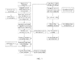
- FIG. 1 shows a flow block diagram of the steel tube arch installation construction process according to the method for installing steel tube arches provided by the invention
- FIG. 2 shows a schematic diagram of the construction of erecting the steel tube arch assembling bracket according to the method for installing steel tube arches provided by the invention
- FIG. 3 shows a schematic diagram of the construction of assembling the steel tube arch according to the method for installing steel tube arches provided by the invention
- FIG. 4 shows a schematic diagram of the construction of installing temporary tie rods according to the method for installing steel tube arches provided by the invention
- FIG. 5 shows a schematic diagram of the construction of dismantling the assembling bracket according to the method for installing steel tube arches provided by the invention
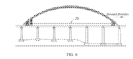
- FIG. 6 shows a first schematic diagram of the construction of the longitudinal movement of the steel tube arch according to the method for installing steel tube arches provided by the invention
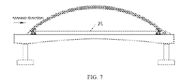
- FIG. 7 shows a second schematic diagram of the construction of the longitudinal movement of the steel tube arch according to the method for installing steel tube arches provided by the invention
- FIG. 8 shows a schematic diagram of the construction of erecting arch springing brackets and assembling small mileage arch springing segments according to the method for installing steel tube arches provided by the invention
- FIG. 9 shows a schematic diagram of the construction of the steel tube arch closure according to the method for installing steel tube arches provided by the invention.
- FIG. 10 shows a schematic diagram of the construction of arch falling and temporary auxiliary facilities dismantling according to the method for installing steel tube arches provided by the invention
- FIG. 11 shows a schematic diagram of the construction of concrete and suspender in the arch according to the method for installing steel tube arches provided by the invention
- FIG. 12 shows a schematic diagram of the facade layout of the steel tube arch assembling bracket according to the method for installing steel tube arches provided by the invention
- FIG. 13 shows a schematic top view of the steel tube arch assembling bracket according to the method for installing steel tube arches provided by the invention
- FIG. 14 shows a schematic front view of the structure of the steel tube arch assembling bracket according to the method for installing steel tube arches provided by the invention
- FIG. 15 shows a schematic side view of the structure of the steel tube arch assembling bracket according to the method for installing steel tube arches provided by the invention
- FIG. 16 shows a schematic front view of the fixed structure of the steel tube upright post foundation according to the method for installing steel tube arches provided by the invention
- FIG. 17 shows a schematic top view of the fixed structure of the steel tube upright post foundation according to the method for installing steel tube arches provided by the invention
- FIG. 18 shows a front view of the structure of the steel tube connection according to the method for installing steel tube arches provided by the invention
- FIG. 19 shows a schematic top view of the structure of the steel tube connection according to the method for installing steel tube arches provided by the invention.
- FIG. 20 shows a schematic front view of the corbel at the pile top according to the method for installing steel tube arches provided by the invention
- FIG. 21 shows a schematic side view of the corbel at the pile top according to the method for installing steel tube arches provided by the invention
- FIG. 22 shows a schematic front view of the structure of the steel tube arch support according to the method for installing steel tube arches provided by the invention
- FIG. 23 shows a schematic side view of the structure of steel tube arch support according to the method for installing steel tube arches provided by the invention
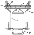
- FIG. 24 shows a structural schematic diagram of the arch springing longitudinally moving trolley according to the method for installing steel tube arches provided by the invention
- FIG. 25 shows a sectional view of the arch springing longitudinally moving trolley according to the method for installing steel tube arches provided by the invention
- FIG. 26 shows a side view of the arch springing longitudinally moving trolley according to the method for installing steel tube arches provided by the invention
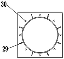
- fixing seat 25. temporary tie rod; 26. steel tube arch; 261. assembling bracket; 262. arch springing bracket; 263. small mileage arch springing segment; 27. steel tube upright post; 28. support plate; 29. stiffening plate; 30. steel bars; 31. braces; 32. backing plate; 33. tray; 34. spandrel girder; 35. diagonal bracing; 36. connecting plate; 37. box girder; 38. upper chord; 39. lower chord; 40. web plate.
- a method for installing steel tube arches 26 comprises the following steps:
- Step S1 erecting a steel tube arch assembling bracket 261 of a longitudinally moving segment, as shown in FIG. 2:
- Step S2 assembling a steel tube arch 26 of the longitudinally moving segment, as shown in FIG. 3:
- Step S3 installing temporary tie rods 25, as shown in FIG. 4:
- Step S4 dismantling the assembling bracket 261, as shown in FIG. 5:
- Step S5 longitudinally moving the steel tube arch 26, as shown in FIGs. 6-7:
- Step S6 erecting an arch springing bracket 262 and assembling small mileage arch springing segments 263, as shown in FIG. 8:
- Step S7 closing the steel tube arch 26, as shown in FIG. 9:
- Step S8 arch falling and temporary auxiliary facilities dismantling, as shown in FIG. 10:
- Step S9 construction of concrete and suspender in arch:
- the overall horizontal length of the longitudinally moving segment is 185.5m, the axial length is 202.1m, the steel tube arch 26 height is 39.2m, and the assembling height is about 39.2 m; the longitudinally moving segment is divided into 15 segments, the horizontal length of the largest segment is 16.9m, and the weight of single arch rib is about 26.3t; the specific construction method is as follows:
- the arch springing longitudinally moving trolley 106 comprises a vehicle body 1, a supporting device 101 above the vehicle body 1, a lifting device 102 inside the vehicle body 1, a crossed hoisting device 20, a walking device 103 under the vehicle body 1, a drive motor 9 and a servo motor 15, the drive motor 9 drives the lifting device 102 to lift, the lifting device 102 further drives the supporting device 101 to lift to support the arch springing, the crossed hoisting device 20 is used to support the lifting device 102, and the servo motor 15 is used to drive the walking device 103 moving further to drive the vehicle body 1;
- the lifting device 102 comprises a sliding plate 5, a fixed pulley 6, a movable pulley 7, two ends of the sliding plate 5 are inlaid with balls 19 which are in rolling contact with the inner wall of the vehicle body 1, two ends of the bottom of the sliding plate 5 are fixedly connected with a plurality of brackets 18, and the bottom ends of the brackets 18 are movably abutted with the inner bottom of the vehicle body
- the power transmission module 105 comprises a worm 10 fixedly connected with an output shaft of the drive motor 9, a worm gear 11 and a winding reel 12 rotatably connected with an inner top of the vehicle body 1, the winding reel 12 is fixedly connected to a front side of the worm gear 11, and the worm 10 is engaged with the worm gear 11; the other end of the steel wire rope 8 is wound and fixedly connected to the winding reel 12.
- the supporting device 101 comprises an inclined frame 2, a top side of the inclined frame 2 is screwed with a plurality of arch springing fixing bolts 3, a bottom of the inclined frame 2 is fixedly connected with a plurality of support rods 4, and bottom ends of the support rods 4 extend to the middle part of the inner side of the vehicle body 1 and are fixedly connected with the sliding plate 5.
- the crossed hoisting device 20 comprise a crossed lifting rod 201 and a piston rod 202 arranged on the crossed lifting rod 201; a control power supply 203 is arranged at a bottom of the inner side of the vehicle body 1, and one end of the piston rod 202 is connected with the control power supply 203 through a line; the crossed hoisting device 20 is arranged at the bottom and middle section of the sliding plate 5 and is fixedly connected with the inner bottom of the vehicle body 1.
- the walking device 103 comprises a traveling frame 13, the traveling frame 13 is fixedly connected to both sides of the bottom of the vehicle body 1, a plurality of sets of wheels 14 are rotatably connected to the traveling frame 13; the servo motor 15 is fixedly connected to the bottom of the vehicle body 1, sprockets 16 are arranged on the front end of the wheels 14, the front side of the traveling frame 13 and the output shaft of the servo motor 15, and the wheels 14 are coaxially driven with the corresponding sprockets 16; the front side of the travelling frame 13 is rotatably connected with the corresponding sprocket 16; the output shaft of the servo motor 15 is fixedly sleeved with the corresponding sprockets 16, and an identical chain 17 is drivingly connected to a plurality of groups of sprockets 16.
- the arch springing longitudinally moving trolley 106 further comprises a stabilizing device 104, the stabilizing device 104 is arranged on the outside of the vehicle body1, the stabilizing device 104 comprises a fixed base 21 and a balancing rod 22 arranged on the fixed base 21, one end of the balancing rod 22 is movably connected with the fixed base 21, the other end of the balancing rod 22 is movably connected with a fixing rod 23, and one end of the fixing rod 23 is provided with a fixing seat 24.
- the balancing rod 22 moves circularly around the fixed base 21 and the balancing rod 22 has a zigzag structure, and the fixing rod 23 is placed inside the balancing rod when retracted.
- the above-mentioned wheels 14 are laid on the track, which is laid on the pile foundation.
- the inclined frame 2 is attached to the bottom of the arch springing, and the arch springing is fixed on the inclined frame 2 through the arch springing fixing bolts 3.
- the drive motor 9 is started, which drives the worm gear 11 and the winding reel 12 to rotate, and the winding reel 12 rotates to wind up the steel wire rope 8.
- the steel wire rope 8 can lift the sliding plate 5 by pulling the movable pulley 7.
- the control power supply 203 is started at the same time as the drive motor 9 is started.
- the control power supply 203 transmits the current to the piston rod 202 through the line, and the piston rod 202 moves to drive the crossed lifting rod 201 to move.
- the sliding plate 5 lifts the inclined frame 2 and the arch springing through the supporting rod 4 and the crossed hoisting device 20;
- the drive motor 9 is stopped, the wire rope 8 will not continue to pull the pulley 7 to make the sliding plate rise, and the crossed hoisting device 20 will also stop working.
- the crossed hoisting device 20 that stops working provides support force for the sliding plate 5 and fixes the sliding plate 5 at this height.
- the servo motor 15 is started and drives a plurality of groups of sprockets 16 to rotate at the same time through the chain 17, and the sprockets 16 drive the wheels 14 to travel on the track, which is convenient for moving the position of the arch springing; when the arch springing is lifted to a predetermined position, the balancing rod 22 in the stabilizing device extends, and then the fixing rod 23 provided on it extends until the fixing seat 24 provided at one end of the fixing rod 23 contacts the ground, so that the vehicle body 1 is balanced and stabilized on the ground.
- a bracket foundation is reliably connected with the girder body, anchor bars are embedded during the construction of the 48m simply supported girder, a16mm bottom plate is arranged at a top to be connected with upright posts, 8 anchor bars of 25mm threaded steel bars 30 are arranged, and bottoms of the anchor bars are connected with the steel bars 30 of the girder body as a whole.
- the steel tube arch assembling bracket 261 of the longitudinally moving segment is arranged on a 32m simply supported box girder 37 bridge deck between piers, and 14 rows of steel tubes are symmetrically arranged on the bracket, every two rows of steel tube upright posts 27 are arranged into a group to form a lattice structure, and an space of about 22m for assembling the steel tube arches 26 is reserved between the two groups, and each steel tube arch 26 assembling segment is supported on two groups ofbrackets.
- step S1 800x10mm steel tubes are used as support steel tube upright posts 27, and four steel tubes are arranged in each group, the horizontal spacing of each group of steel tube upright posts 27 is 7.0m, and the longitudinal spacing is 3.0 ⁇ 5.0m, HN450x200mm or 20 profile steel lateral bracings are arranged between the steel tube upright posts 27, and bottoms of the upright posts 27 are welded and fixed with the embedded parts at an upper part of the girder body, tops of each row of steel tube upright posts 27 are provided with double-assembled H450x200mm profile steels as spandrel girders, with overhanging tripods at both ends, the spandrel girders are provided with crescent-shaped steel tube arch tray 33 assemblies and steel tube arch braces 31.
- step S1 during construction of cast-in-place box girder 37, 25 anchor bars are embedded on a top of the girder in advance, the anchoring depth of the anchor bars is less than 40cm, and the anchor bars are connected with the steel bars 30 of the girder as a whole; before the installation of steel tube upright posts 27, a16mm thick bottom plate is installed and fixed with M24 sleeves, and steel tube upright posts 27 are welded with the bottom plate, so that a floor and the girder surface are closely attached during construction.
- the steel tube upright posts 27 are processed in a back yard according to a bottom elevation of the steel tube and a top elevation of steel tube upright posts 27; in order to ensure the stability of the steel tube upright posts 27, the steel tube upright posts 27 and lateral bracings should be constructed synchronously, and the installation verticality is less than or equal to H/500 and not more than 5cm, the extension of the steel tube in a back yard and a front yard are welded by penetration welding, and 6 connecting plates 36 with a thickness of 12mm are welded on the outside, the dimension of the connecting plates 36 is 300mmx150mmx12mm.
- lateral bracings and diagonal bracings 35 are processed according to drawings in a back yard, and the truck crane and steel tube upright posts 27 are used for synchronous construction on site; before the lateral bracings are hoisted, elevation positions of the lateral bracings are accurately set out according to drawings, and the quality and thickness of welds between the lateral bracings and steel tubes, lateral bracings and diagonal bracings 35 are strictly controlled during construction; all the lateral bracings are connected by full welding, the thickness of the weld shall not be less than the thickness ofbase metal, and the intersections of the two diagonal bracings 35 shall be welded as a whole; there shall be no defects ofpores, slag inclusions, arc pits, cracks and full welding on the weld surface; the next stage of construction can only be carried out after an on-site quality inspector checks and confirms that the welding seam of steel tube pile connection is qualified; the four steel tubes of an identical steel tube lattic
- spandrel girders 34 are of double-assembled HN450 ⁇ 200 profile steel, and are hoisted on the box girder 37 by a truck crane; before the installation of the spandrel girder 34, pile top notches are cut and bearing corbels are welded on site; elevations of top surfaces of the corbels and the pile top notches are measured and set out, and the elevation and stability of pile corbel surfaces are strictly controlled; skilled workers are arranged to cut notches to ensure that the cutting surfaces of the notches are flat, and the corbels are installed after the notches are cut; elevations of corbel panels are measured accurately, and elevation differences between four corners and the center of the panel is less than 2mm.
- a crescent-shaped steel tube supporting base device is arranged at a top of the bracket, and the device comprises supporting plates 28, backing plates 32 and stiffening plates 29, wherein the supporting plates are all of 24mm thick steel plates, and the supporting base is processed and formed in a factory, and fixed and installed on site, and one supporting base is installed at each of both ends of each assembled segment.
- the steel tube arch of the main bridge is divided into three parts: an arch springing segment, an inlaying segment and a longitudinally moving segment, wherein the large mileage side embedded segment of the arch springing segment is embedded in advance, and the small mileage side embedded segment is embedded and arch support constructed after the longitudinally moving segment is longitudinally moved into position.
- the method of “heterotopic bracket assembly and integral longitudinal movement” is proposed for construction of the steel tube arch of the longitudinally moving segment.
- the steel tube arch is directly closed by “matching cutting method” at a predetermined temperature, and the specific construction method is as follows:
- Construction of the inlaying segment “Matching cutting method” is used for steel tube arch closure, that is, before closure, continuously observe the size of closure opening, match and cut the length of inlaying segment, then directly inlay the inlaying segment at a suitable temperature, and use a clamp plate to temporarily weld and lock it.
- the construction of the inlaying segment should be carried out when the temperature is relatively stable. Before the closure connection, the arch axis shall be finally adjusted accurately, and the closure connection shall be carried out after it is confirmed to be consistent with the design;
- suspender construction After the concrete strength in the arch meets the requirements, the installation of suspenders shall be carried out according to the principle of first long suspenders and then short suspenders, and the suspenders shall be tensioned by tripping off, and the single-end one-time tensioning process shall be adopted;
- the method for installing steel tube arches provided by the invention is safe, standardized and reliable, and the construction standard is prone to control.
- the method reduces the operation difficulty and construction risk of workers, provides high safety, improves the construction efficiency, and is suitable for extended application.
Abstract
A method for installing steel tube arches, which comprises the following steps: step S1, erecting a steel tube arch assembling bracket (261); step S2, assembling a steel tube arch (26); step S3, installing temporary tie rods (25) of the steel tube arch (26); step S4, dismantling the assembling bracket (261); step S5, longitudinally moving the steel tube arch (26); step S6, erecting an arch springing bracket (262) and assembling small mileage arch springing segments (263); step S7, closing the steel tube arch (26); S8, arch falling and temporary auxiliary facilities dismantling; step S9, construction of concrete and suspender in arch. The method for installing steel tube arches provided by the invention is safe, standardized and reliable, and the construction standard is prone to control.
Description
FIELD OF TECHNOLOGY
The invention relates to the technical field of bridge construction, in particular to a method for installing steel tube arches.
With the rapid development of economy and society, especially the acceleration of urbanization, the bottom-bearing beam-arc composite bridge with steel tube arch, as a bridge across existing roads, railways, valleys and rivers, has the advantages of saving materials and large span, and has been widely used. In the construction process of this kind of bridge, the installation and construction method of the steel tube arch directly affects the construction quality, construction efficiency and safety of the bridge. Upon search, the Chinese patent document with the authorized publication number of CN110205938B discloses a method for installing steel tube arches of bottom-bearing beam-arch composite bridge, including embedding a first arch support, a vertical hinged support, a low bracket base, a fixed pedestal, a girder surface track and a notch steel bar of the second arch support; erecting a temporary low support; assembling a first group of steel tube arch ribs and a second group of steel tube arch ribs to form a middle hinge; making the first group of steel tube arch ribs and the vertical hinged support form a first hinge, and the second group of steel tube arch ribs and a moving trolley form a second hinge; connecting the moving trolley and the tensioning device arranged on the fixed pedestal with a steel strand; starting the tensioning device to pull the moving trolley to make the second group of steel tube arch ribs move horizontally along the track on the girder surface, and gradually arching the first group of steel tube arch ribs and the second group of steel tube arch ribs at the middle hinge until the vault reaches the design position; consolidating and pouring the second group of steel tube arch ribs and the notch steel bar; dismantling temporary facilities, installing inlaying segments at the middle hinge and the first hinge, and filling them with pumped concrete.
However, the design for existing steel tube arch installation process is unreasonable, the construction operation is cumbersome and difficult, the construction period is long, the number of difficult operations is large, the safety risk is high, and construction accidents are prone to occur, so it is necessary to improve the design. Therefore, the invention provides a method for installing steel tube arches to solve the above problems.
SUMMARY
The object of the invention is to overcome the shortcomings of the prior art and provide a method for installing steel tube arches.
In order to achieve the above object, the invention adopts the following technical solutions:
A method for installing steel tube arches comprises the following steps:
step S1, erecting a steel tube arch assembling bracket;
step S2, assembling the steel tube arch;
(1) assembling small steel tube arch segments into installation segments;
(2) installing arch springing longitudinally moving trolleys on both sides of the steel tube arch;
(3) using two truck cranes to symmetrically assemble the assembled installation segments according to the sequence from the arch springing to the vault;
step S3, installing a temporary tie rod of the steel tube arch and stretching it to form a temporary tied arch structure;
step S4, dismantling the assembling bracket symmetrically from the middle to both sides;
step S5, longitudinally moving the steel tube arch:
(1) after the closure of the continuous girder of the main bridge, laying and installing the longitudinally moving track and debugging the longitudinal jack system;
(2) using the jacks to smoothly and continuously push the steel tube arch vault to the designed lifting position of the main span;
step S6, erecting an arch springing bracket and assembling small mileage arch springing segments;
(1) using a tower crane to erect small mileage arch springing brackets;
(2) pouring arch springing concrete;
step S7, closing the steel tube arch:
(1) continuously measuring the dimension of closure opening;
(2) matching and cutting the steel tube arch of an inlaying segment according to the measured data;
(3) completing closure construction of the steel tube arch at a closure temperature;
step S8, arch falling and dismantling temporary auxiliary facilities: unloading temporary tie rod in stages, and dismantling the arch springing longitudinally moving trolleys;
step S9, construction of concrete and suspender in arch:
(1) pumping and injecting arch rib concrete with pressure according to the sequence of the upper chord first, then the lower chord, then the web plate;
(2) installing the long suspender first and then installing the short suspender, and tensioning the suspender.
Preferably, the arch springing longitudinally moving trolley comprises a vehicle body, asupporting device above the vehicle body, a lifting device inside the vehicle body, a crossed hoisting device, a walking device under the vehicle body, a drive motor and a servo motor, the drive motor drives the lifting device to lift, the lifting device further drives the supporting device to lift to support the arch springing, the crossed hoisting device is used to support the lifting device, and the servo motor is used to drive the walking device moving further to drive the vehicle body; the lifting device comprises a sliding plate, a fixed pulley, a movable pulley, two ends of the sliding plate are inlaid with balls which are in rolling contact with the inner wall of the vehicle body, two ends of the bottom of the sliding plate 5 are fixedly connected with a plurality ofbrackets, and the bottom ends of the brackets are movably abutted with the inner bottom of the vehicle body; the fixed pulley is fixedly connected with a top of the inner side of the vehicle body, several movable pulleys are fixedly connected with the bottom of the sliding plate, and the several movable pulleys and the fixed pulley are wound with an identical steel wire rope; one end of the steel wire rope is fixedly connected to the inner wall of the vehicle body; the drive motor is connected with the steel wire rope with a power transmission module.
Preferably, the power transmission module comprises a worm fixedly connected with an output shaft of the drive motor, a worm gear and a winding reel rotatably connected with an inner top of the vehicle body, the winding reel is fixedly connected to a front side of the worm gear, and the worm is engaged with the worm gear; the other end of the steel wire rope is wound and fixedly connected to the winding reel.
Preferably, the supporting device comprises an inclined frame, a top side of the inclined frame is screwed with a plurality of arch springing fixing bolts, a bottom of the inclined frame is fixedly connected with a plurality of support rods, and bottom ends of the support rods extend to the middle part of the inner side of the vehicle body and are fixedly connected with the sliding plate.
Preferably, the crossed hoisting device comprise a crossed lifting rod and a piston rod arranged on the crossed lifting rod; a control power supply is arranged at a bottom of the inner side of the vehicle body, and one end of the piston rod is connected with the control power supply through a line; the crossed hoisting device is arranged at the bottom and middle section of the sliding plate and is fixedly connected with the inner bottom of the vehicle body.
Preferably, the walking device comprises a traveling frame, the traveling frame is fixedly connected to both sides of the bottom of the vehicle body, a plurality of sets of wheels are rotatably connected to the traveling frame; the servo motor is fixedly connected to the bottom of the vehicle body, sprockets are arranged on the front end of the wheels, the front side of the traveling frame and the output shaft of the servo motor, and the wheels are coaxially driven with the corresponding sprockets; the front side of the travelling frame is rotatably connected with the corresponding sprocket; the output shaft of the servo motor is fixedly sleeved with the corresponding sprockets, and an identical chain is drivingly connected to a plurality of groups of sprockets.
Preferably, the arch springing longitudinally moving trolley further comprises a stabilizing device, the stabilizing device is arranged on the outside of the vehicle body, thestabilizing device comprises a fixed base and a balancing rod arranged on the fixed base, one end of the balancing rod is movably connected with the fixed base, the other end of the balancing rod is movably connected with a fixing rod, and one end of the fixing rod is provided with a fixing seat.
The method for installing steel tube arches provided by the invention is safe, standardized and reliable, and the construction standard is prone to control. the arch springing longitudinally moving trolley used in the present invention is easy to operate and save labor cost.
FIG. 1 shows a flow block diagram of the steel tube arch installation construction process according to the method for installing steel tube arches provided by the invention;
FIG. 2 shows a schematic diagram of the construction of erecting the steel tube arch assembling bracket according to the method for installing steel tube arches provided by the invention;
FIG. 3 shows a schematic diagram of the construction of assembling the steel tube arch according to the method for installing steel tube arches provided by the invention;
FIG. 4 shows a schematic diagram of the construction of installing temporary tie rods according to the method for installing steel tube arches provided by the invention;
FIG. 5 shows a schematic diagram of the construction of dismantling the assembling bracket according to the method for installing steel tube arches provided by the invention;
FIG. 6 shows a first schematic diagram of the construction of the longitudinal movement of the steel tube arch according to the method for installing steel tube arches provided by the invention;
FIG. 7 shows a second schematic diagram of the construction of the longitudinal movement of the steel tube arch according to the method for installing steel tube arches provided by the invention;
FIG. 8 shows a schematic diagram of the construction of erecting arch springing brackets and assembling small mileage arch springing segments according to the method for installing steel tube arches provided by the invention;
FIG. 9 shows a schematic diagram of the construction of the steel tube arch closure according to the method for installing steel tube arches provided by the invention;
FIG. 10 shows a schematic diagram of the construction of arch falling and temporary auxiliary facilities dismantling according to the method for installing steel tube arches provided by the invention;
FIG. 11 shows a schematic diagram of the construction of concrete and suspender in the arch according to the method for installing steel tube arches provided by the invention;
FIG. 12 shows a schematic diagram of the facade layout of the steel tube arch assembling bracket according to the method for installing steel tube arches provided by the invention;
FIG. 13 shows a schematic top view of the steel tube arch assembling bracket according to the method for installing steel tube arches provided by the invention;
FIG. 14 shows a schematic front view of the structure of the steel tube arch assembling bracket according to the method for installing steel tube arches provided by the invention;
FIG. 15 shows a schematic side view of the structure of the steel tube arch assembling bracket according to the method for installing steel tube arches provided by the invention;
FIG. 16 shows a schematic front view of the fixed structure of the steel tube upright post foundation according to the method for installing steel tube arches provided by the invention;
FIG. 17 shows a schematic top view of the fixed structure of the steel tube upright post foundation according to the method for installing steel tube arches provided by the invention;
FIG. 18 shows a front view of the structure of the steel tube connection according to the method for installing steel tube arches provided by the invention;
FIG. 19 shows a schematic top view of the structure of the steel tube connection according to the method for installing steel tube arches provided by the invention;
FIG. 20 shows a schematic front view of the corbel at the pile top according to the method for installing steel tube arches provided by the invention;
FIG. 21 shows a schematic side view of the corbel at the pile top according to the method for installing steel tube arches provided by the invention;
FIG. 22 shows a schematic front view of the structure of the steel tube arch support according to the method for installing steel tube arches provided by the invention;
FIG. 23 shows a schematic side view of the structure of steel tube arch support according to the method for installing steel tube arches provided by the invention;
FIG. 24 shows a structural schematic diagram of the arch springing longitudinally moving trolley according to the method for installing steel tube arches provided by the invention;
FIG. 25 shows a sectional view of the arch springing longitudinally moving trolley according to the method for installing steel tube arches provided by the invention;
FIG. 26 shows a side view of the arch springing longitudinally moving trolley according to the method for installing steel tube arches provided by the invention;
Description of reference signs in the drawings: 101. supporting device; 102. lifting device; 103. walking device; 104. stabilizing device; 105. power transmission module; 106. arch springing longitudinally moving trolley; 1. vehicle body; 2. inclined frame; 3. arch springing fixing bolts; 4. support rods; 5. sliding plate; 6. fixed pulley; 7. movable pulley; 8. steel wire rope; 9. drive motor; 10. worm; 11. worm gear; 12. winding reel; 13. travelling frame; 14. wheels; 15. servo motor; 16. sprocket; 17. chain; 18. bracket; 19. ball; 20. crossed hoisting device; 201. crossed lifting rod; 202. piston rod; 203. control power supply; 21. fixed base; 22. balancing rod; 23. fixing rod; 24. fixing seat; 25. temporary tie rod; 26. steel tube arch; 261. assembling bracket; 262. arch springing bracket; 263. small mileage arch springing segment; 27. steel tube upright post; 28. support plate; 29. stiffening plate; 30. steel bars; 31. braces; 32. backing plate; 33. tray; 34. spandrel girder; 35. diagonal bracing; 36. connecting plate; 37. box girder; 38. upper chord; 39. lower chord; 40. web plate.
DESCRIPTION OF THE EMBODIMENTS
The technical solution in the embodiments of the invention will be described clearly and completely with reference to the drawings corresponding to the embodiments. Obviously, the described embodiments are only part of the embodiments of the invention, not the whole.
Referring to FIGs. 1-23, a method for installing steel tube arches 26 comprises the following steps:
Step S1, erecting a steel tube arch assembling bracket 261 of a longitudinally moving segment, as shown in FIG. 2:
Erecting a steel tube arch assembling bracket of a longitudinally moving segment on a 32m cast-in-place box girder 37 between piers on a shore side;
Step S2, assembling a steel tube arch 26 of the longitudinally moving segment, as shown in FIG. 3:
(1) assembling steel tube arch segments into 15 segments in the processing plant and assembling the 15 segments into 9 installation segments on site;
(2) installing arch springing longitudinally moving trolleys 106 on both sides of the steel tube arch 26 of the longitudinally moving segment;
(3) using two 160t truck cranes to symmetrically assemble the assembled installation segments according to the sequence from the arch springing to the vault to complete the steel tube arch 26 of the longitudinally moving segment;
Step S3, installing temporary tie rods 25, as shown in FIG. 4:
installing temporary tie rods of the steel tube arch 26 of the longitudinally moving segment and stretching them to form a temporary tied arch structure;
Step S4, dismantling the assembling bracket 261, as shown in FIG. 5:
(1) using a 50t truck crane to hang the assembling bracket 261 over the bridge deck and removing the assembling bracket 261 symmetrically from the middle to both sides;
(2) in the process of bracket dismantling, monitoring the stress and alignment of the steel tube arch 26, and properly adjust the tensioning force of the temporary tie rods 25;
Step S5, longitudinally moving the steel tube arch 26, as shown in FIGs. 6-7:
(1) after the closure of the continuous girder of the main bridge, laying and installing the longitudinally moving track and debugging the longitudinal jack system;
(2) using 4 sets of 50t jacks to smoothly and continuously push the steel tube arch 26 vault to the designed lifting position of the main span;
Step S6, erecting an arch springing bracket 262 and assembling small mileage arch springing segments 263, as shown in FIG. 8:
(1) using a tower crane to erect small mileage arch springing brackets 262;
(2) pouring arch springing concrete;
Step S7, closing the steel tube arch 26, as shown in FIG. 9:
(1) continuously measuring the dimension of closure opening;
(2) matching and cutting the steel tube arch of an inlaying segment in a back yard according to the measured data;
(3) completing closure construction of the steel tube arch 26 at a closure temperature;
Step S8, arch falling and temporary auxiliary facilities dismantling, as shown in FIG. 10:
unloading temporary tie rods 25 in stages, and dismantling arch springing longitudinally moving trolleys;
Step S9, construction of concrete and suspender in arch:
(1) pumping and injecting arch rib concrete with pressure according to the sequence of the upper chord first, then the lower chord, then the web plate;
(2) installing the long suspender first and then installing the short suspender, and tensioning the suspender according to the sequence specified in design drawings.
In this embodiment, in the step S2, the overall horizontal length of the longitudinally moving segment is 185.5m, the axial length is 202.1m, the steel tube arch 26 height is 39.2m, and the assembling height is about 39.2 m; the longitudinally moving segment is divided into 15 segments, the horizontal length of the largest segment is 16.9m, and the weight of single arch rib is about 26.3t; the specific construction method is as follows:
After 15 processed segments are transported to site, assemble the processed segments into 9 installation segments in a back yard, the maximum axis length of the assembled segments is about 31.7m and the weight is about 47t; then, using two 160t truck cranes to lift and install the segments, and assembling the segments on the steel tube support on the 4x48m cast-in-place box girder 37, and the assembling sequence is from both ends to the top.
As shown in FIG. 24-26, the arch springing longitudinally moving trolley 106 comprises a vehicle body 1, a supporting device 101 above the vehicle body 1, a lifting device 102 inside the vehicle body 1, a crossed hoisting device 20, a walking device 103 under the vehicle body 1, a drive motor 9 and a servo motor 15, the drive motor 9 drives the lifting device 102 to lift, the lifting device 102 further drives the supporting device 101 to lift to support the arch springing, the crossed hoisting device 20 is used to support the lifting device 102, and the servo motor 15 is used to drive the walking device 103 moving further to drive the vehicle body 1; the lifting device 102 comprises a sliding plate 5, a fixed pulley 6, a movable pulley 7, two ends of the sliding plate 5 are inlaid with balls 19 which are in rolling contact with the inner wall of the vehicle body 1, two ends of the bottom of the sliding plate 5 are fixedly connected with a plurality of brackets 18, and the bottom ends of the brackets 18 are movably abutted with the inner bottom of the vehicle body 1; the fixed pulley 6 is fixedly connected with a top of the inner side of the vehicle body 1, several movable pulleys 7 are fixedly connected with the bottom of the sliding plate 5, and the several movable pulleys 7 and the fixed pulley 6 are wound with an identical steel wire rope 8; one end of the steel wire rope 8 is fixedly connected to the inner wall of the vehicle body 1; the drive motor 9 is connected with the steel wire rope 8 with a power transmission module 105.
The power transmission module 105 comprises a worm 10 fixedly connected with an output shaft of the drive motor 9, a worm gear 11 and a winding reel 12 rotatably connected with an inner top of the vehicle body 1, the winding reel 12 is fixedly connected to a front side of the worm gear 11, and the worm 10 is engaged with the worm gear 11; the other end of the steel wire rope 8 is wound and fixedly connected to the winding reel 12.
The supporting device 101 comprises an inclined frame 2, a top side of the inclined frame 2 is screwed with a plurality of arch springing fixing bolts 3, a bottom of the inclined frame 2 is fixedly connected with a plurality of support rods 4, and bottom ends of the support rods 4 extend to the middle part of the inner side of the vehicle body 1 and are fixedly connected with the sliding plate 5.
The crossed hoisting device 20 comprise a crossed lifting rod 201 and a piston rod 202 arranged on the crossed lifting rod 201; a control power supply 203 is arranged at a bottom of the inner side of the vehicle body 1, and one end of the piston rod 202 is connected with the control power supply 203 through a line; the crossed hoisting device 20 is arranged at the bottom and middle section of the sliding plate 5 and is fixedly connected with the inner bottom of the vehicle body 1.
The walking device 103 comprises a traveling frame 13, the traveling frame 13 is fixedly connected to both sides of the bottom of the vehicle body 1, a plurality of sets of wheels 14 are rotatably connected to the traveling frame 13; the servo motor 15 is fixedly connected to the bottom of the vehicle body 1, sprockets 16 are arranged on the front end of the wheels 14, the front side of the traveling frame 13 and the output shaft of the servo motor 15, and the wheels 14 are coaxially driven with the corresponding sprockets 16; the front side of the travelling frame 13 is rotatably connected with the corresponding sprocket 16; the output shaft of the servo motor 15 is fixedly sleeved with the corresponding sprockets 16, and an identical chain 17 is drivingly connected to a plurality of groups of sprockets 16.
The arch springing longitudinally moving trolley 106 further comprises a stabilizing device 104, the stabilizing device 104 is arranged on the outside of the vehicle body1, the stabilizing device 104 comprises a fixed base 21 and a balancing rod 22 arranged on the fixed base 21, one end of the balancing rod 22 is movably connected with the fixed base 21, the other end of the balancing rod 22 is movably connected with a fixing rod 23, and one end of the fixing rod 23 is provided with a fixing seat 24. The balancing rod 22 moves circularly around the fixed base 21 and the balancing rod 22 has a zigzag structure, and the fixing rod 23 is placed inside the balancing rod when retracted.
The above-mentioned wheels 14 are laid on the track, which is laid on the pile foundation. The inclined frame 2 is attached to the bottom of the arch springing, and the arch springing is fixed on the inclined frame 2 through the arch springing fixing bolts 3. Then, the drive motor 9 is started, which drives the worm gear 11 and the winding reel 12 to rotate, and the winding reel 12 rotates to wind up the steel wire rope 8. The steel wire rope 8 can lift the sliding plate 5 by pulling the movable pulley 7. The control power supply 203 is started at the same time as the drive motor 9 is started. The control power supply 203 transmits the current to the piston rod 202 through the line, and the piston rod 202 moves to drive the crossed lifting rod 201 to move. The sliding plate 5 lifts the inclined frame 2 and the arch springing through the supporting rod 4 and the crossed hoisting device 20; When the arch springing reaches a predetermined height, the drive motor 9 is stopped, the wire rope 8 will not continue to pull the pulley 7 to make the sliding plate rise, and the crossed hoisting device 20 will also stop working. At this time, the crossed hoisting device 20 that stops working provides support force for the sliding plate 5 and fixes the sliding plate 5 at this height. Then, the servo motor 15 is started and drives a plurality of groups of sprockets 16 to rotate at the same time through the chain 17, and the sprockets 16 drive the wheels 14 to travel on the track, which is convenient for moving the position of the arch springing; when the arch springing is lifted to a predetermined position, the balancing rod 22 in the stabilizing device extends, and then the fixing rod 23 provided on it extends until the fixing seat 24 provided at one end of the fixing rod 23 contacts the ground, so that the vehicle body 1 is balanced and stabilized on the ground.
In this embodiment, in the step S1, as shown in FIG. 16-17, a bracket foundation is reliably connected with the girder body, anchor bars are embedded during the construction of the 48m simply supported girder, a16mm bottom plate is arranged at a top to be connected with upright posts, 8 anchor bars of 25mm threaded steel bars 30 are arranged, and bottoms of the anchor bars are connected with the steel bars 30 of the girder body as a whole.
In this embodiment, in the step S1, as shown in FIG. 12-13, the steel tube arch assembling bracket 261 of the longitudinally moving segment is arranged on a 32m simply supported box girder 37 bridge deck between piers, and 14 rows of steel tubes are symmetrically arranged on the bracket, every two rows of steel tube upright posts 27 are arranged into a group to form a lattice structure, and an space of about 22m for assembling the steel tube arches 26 is reserved between the two groups, and each steel tube arch 26 assembling segment is supported on two groups ofbrackets.
In this embodiment, in the step S1, as shown in FIG. 14-15, 800x10mm steel tubes are used as support steel tube upright posts 27, and four steel tubes are arranged in each group, the horizontal spacing of each group of steel tube upright posts 27 is 7.0m, and the longitudinal spacing is 3.0~5.0m, HN450x200mm or 20 profile steel lateral bracings are arranged between the steel tube upright posts 27, and bottoms of the upright posts 27 are welded and fixed with the embedded parts at an upper part of the girder body, tops of each row of steel tube upright posts 27 are provided with double-assembled H450x200mm profile steels as spandrel girders, with overhanging tripods at both ends, the spandrel girders are provided with crescent-shaped steel tube arch tray 33 assemblies and steel tube arch braces 31.
In this embodiment, in the step S1, as shown in FIG. 12-13, during construction of cast-in- place box girder 37, 25 anchor bars are embedded on a top of the girder in advance, the anchoring depth of the anchor bars is less than 40cm, and the anchor bars are connected with the steel bars 30 of the girder as a whole; before the installation of steel tube upright posts 27, a16mm thick bottom plate is installed and fixed with M24 sleeves, and steel tube upright posts 27 are welded with the bottom plate, so that a floor and the girder surface are closely attached during construction.
In this embodiment, in the step S1, as shown in FIG. 18-19, the steel tube upright posts 27 are processed in a back yard according to a bottom elevation of the steel tube and a top elevation of steel tube upright posts 27; in order to ensure the stability of the steel tube upright posts 27, the steel tube upright posts 27 and lateral bracings should be constructed synchronously, and the installation verticality is less than or equal to H/500 and not more than 5cm, the extension of the steel tube in a back yard and a front yard are welded by penetration welding, and 6 connecting plates 36 with a thickness of 12mm are welded on the outside, the dimension of the connecting plates 36 is 300mmx150mmx12mm.
In this embodiment, in the step S1, lateral bracings and diagonal bracings 35 are processed according to drawings in a back yard, and the truck crane and steel tube upright posts 27 are used for synchronous construction on site; before the lateral bracings are hoisted, elevation positions of the lateral bracings are accurately set out according to drawings, and the quality and thickness of welds between the lateral bracings and steel tubes, lateral bracings and diagonal bracings 35 are strictly controlled during construction; all the lateral bracings are connected by full welding, the thickness of the weld shall not be less than the thickness ofbase metal, and the intersections of the two diagonal bracings 35 shall be welded as a whole; there shall be no defects ofpores, slag inclusions, arc pits, cracks and full welding on the weld surface; the next stage of construction can only be carried out after an on-site quality inspector checks and confirms that the welding seam of steel tube pile connection is qualified; the four steel tubes of an identical steel tube lattice column should be constructed synchronously, and it is forbidden to carry out the next vertical steel tube extension operation if the steel tube lateral bracings has not been welded.
In this embodiment, in the step S1, as shown in FIG. 20-21, spandrel girders 34 are of double-assembled HN450×200 profile steel, and are hoisted on the box girder 37 by a truck crane; before the installation of the spandrel girder 34, pile top notches are cut and bearing corbels are welded on site; elevations of top surfaces of the corbels and the pile top notches are measured and set out, and the elevation and stability of pile corbel surfaces are strictly controlled; skilled workers are arranged to cut notches to ensure that the cutting surfaces of the notches are flat, and the corbels are installed after the notches are cut; elevations of corbel panels are measured accurately, and elevation differences between four corners and the center of the panel is less than 2mm.
In this embodiment, in the step S1, as shown in FIG. 22-23, a crescent-shaped steel tube supporting base device is arranged at a top of the bracket, and the device comprises supporting plates 28, backing plates 32 and stiffening plates 29, wherein the supporting plates are all of 24mm thick steel plates, and the supporting base is processed and formed in a factory, and fixed and installed on site, and one supporting base is installed at each of both ends of each assembled segment.
According to the method for installing steel tube arches provided by the invention, the steel tube arch of the main bridge is divided into three parts: an arch springing segment, an inlaying segment and a longitudinally moving segment, wherein the large mileage side embedded segment of the arch springing segment is embedded in advance, and the small mileage side embedded segment is embedded and arch support constructed after the longitudinally moving segment is longitudinally moved into position. The method of “heterotopic bracket assembly and integral longitudinal movement” is proposed for construction of the steel tube arch of the longitudinally moving segment. The steel tube arch is directly closed by “matching cutting method” at a predetermined temperature, and the specific construction method is as follows:
(1) For construction of steel tube arch of the longitudinally moving segment: During the construction of continuous girder, the steel tube arch of the longitudinally moving segment is hung on the steel tube bracket of simply supported box girder ofpier 89~95 by a truck crane, and the steel tube arch of the longitudinally moving segment is symmetrically assembled in 15 small segments from arch springing to vault. After the construction of the continuous girder of the main bridge is completed, the steel tube arch is “integrally moved longitudinally” to the designed closing position through the longitudinal movement system;
(2) For construction of steel tube arch at arch springing segment: The steel tube arch at small mileage side arch springing segment is assembled after the steel tube arch of the longitudinally moving segment is moved into position, and the steel tube arch at large mileage side can be assembled during the construction of continuous girder of the main bridge. The arch springing segment is assembled in situ by “bracket method” using a truck crane;
(3) Construction of the inlaying segment: “Matching cutting method” is used for steel tube arch closure, that is, before closure, continuously observe the size of closure opening, match and cut the length of inlaying segment, then directly inlay the inlaying segment at a suitable temperature, and use a clamp plate to temporarily weld and lock it. The construction of the inlaying segment should be carried out when the temperature is relatively stable. Before the closure connection, the arch axis shall be finally adjusted accurately, and the closure connection shall be carried out after it is confirmed to be consistent with the design;
(4) Concrete construction in the steel tube arch: After closure of the steel tube arch, concrete in the arch is poured. The arch rib micro-expansive concrete is constructed by pumping lift-up method from low to high. The concrete in the chord pipe is pumped by primary pumping, and the concrete in the web is pumped by secondary pumping. The pumping sequence is: first the upper chord pipe, then the lower chord pipe, and then the web plate. The next ring of concrete can be pumped only after the upper ring of concrete reaches 90%of the design strength;
(5) Suspender construction: After the concrete strength in the arch meets the requirements, the installation of suspenders shall be carried out according to the principle of first long suspenders and then short suspenders, and the suspenders shall be tensioned by tripping off, and the single-end one-time tensioning process shall be adopted;
The method for installing steel tube arches provided by the invention is safe, standardized and reliable, and the construction standard is prone to control. The method reduces the operation difficulty and construction risk of workers, provides high safety, improves the construction efficiency, and is suitable for extended application.
The above are only preferred embodiments of the invention, but the protection scope of the invention is not limited to this. Any equivalent substitution or change made by anyone familiar with the technical field according to the technical solution and inventive concept of the invention within the technical scope disclosed by the invention fall within the protection scope of the invention
Claims (8)
- A method for installing steel tube arches, comprising the following steps:step S1, erecting a steel tube arch assembling bracket;step S2, assembling the steel tube arch;(1) assembling small steel tube arch segments into installation segments;(2) installing arch springing longitudinally moving trolleys on both sides of the steel tube arch;(3) using two truck cranes to symmetrically assemble the assembled installation segments according to the sequence from the arch springing to the vault;step S3, installing a temporary tie rod of the steel tube arch and stretching it to form a temporary tied arch structure;step S4, dismantling the assembling bracket symmetrically from the middle to both sides;step S5, longitudinally moving the steel tube arch:(1) after the closure of the continuous girder of the main bridge, laying and installing the longitudinally moving track and debugging the longitudinal jack system;(2) using the jacks to smoothly and continuously push the steel tube arch vault to the designed lifting position of the main span;step S6, erecting an arch springing bracket and assembling small mileage arch springing segments;(1) using a tower crane to erect small mileage arch springing brackets;(2) pouring arch springing concrete;step S7, closing the steel tube arch:(1) continuously measuring the dimension of closure opening;(2) matching and cutting the steel tube arch of an inlaying segment according to the measured data;(3) completing closure construction of the steel tube arch at a closure temperature;step S8, arch falling and dismantling temporary auxiliary facilities: unloading temporary tie rod in stages, and dismantling the arch springing longitudinally moving trolleys;step S9, construction of concrete and suspender in arch:(1) pumping and injecting arch rib concrete with pressure according to the sequence of the upper chord first, then the lower chord, then the web plate;(2) installing the long suspender first and then installing the short suspender, and tensioning the suspender.
- The method for installing steel tube arches according to claim 1, wherein, the arch springing longitudinally moving trolley comprises a vehicle body, a supporting device above the vehicle body, a lifting device inside the vehicle body, a crossed hoisting device, a walking device under the vehicle body, a drive motor and a servo motor, the drive motor drives the lifting device to lift, the lifting device further drives the supporting device to lift to support the arch springing, the crossed hoisting device is used to support the lifting device, and the servo motor is used to drive the walking device moving further to drive the vehicle body; the lifting device comprises a sliding plate, a fixed pulley, a movable pulley, two ends of the sliding plate are inlaid with balls which are in rolling contact with the inner wall of the vehicle body, two ends of the bottom of the sliding plate 5 are fixedly connected with a plurality of brackets, and the bottom ends of the brackets are movably abutted with the inner bottom of the vehicle body; the fixed pulley is fixedly connected with a top of the inner side of the vehicle body, several movable pulleys are fixedly connected with the bottom of the sliding plate, and the several movable pulleys and the fixed pulley are wound with an identical steel wire rope; one end of the steel wire rope is fixedly connected to the inner wall of the vehicle body; the drive motor is connected with the steel wire rope with a power transmission module.
- The method for installing steel tube arches according to claim 2, wherein, the power transmission module comprises a worm fixedly connected with an output shaft of the drive motor, a worm gear and a winding reel rotatably connected with an inner top of the vehicle body, the winding reel is fixedly connected to a front side of the worm gear, and the worm is engaged with the worm gear; the other end of the steel wire rope is wound and fixedly connected to the winding reel.
- The method for installing steel tube arches according to claim 3, wherein, the supporting device comprises an inclined frame, a top side of the inclined frame is screwed with a plurality of arch springing fixing bolts, a bottom of the inclined frame is fixedly connected with a plurality of support rods, and bottom ends of the support rods extend to the middle part of the inner side of the vehicle body and are fixedly connected with the sliding plate.
- The method for installing steel tube arches according to claim 4, wherein, the crossed hoisting device comprise a crossed lifting rod and a piston rod arranged on the crossed lifting rod; a control power supply is arranged at a bottom of the inner side of the vehicle body, and one end of the piston rod is connected with the control power supply through a line; the crossed hoisting device is arranged at the bottom and middle section of the sliding plate and is fixedly connected with the inner bottom of the vehicle body.
- The method for installing steel tube arches according to claim 5, wherein, the walking device comprises a traveling frame, the traveling frame is fixedly connected to both sides of the bottom of the vehicle body, a plurality of sets of wheels are rotatably connected to the traveling frame; the servo motor is fixedly connected to the bottom of the vehicle body, sprockets are arranged on the front end of the wheels, the front side of the traveling frame and the output shaft of the servo motor, and the wheels are coaxially driven with the corresponding sprockets; the front side of the travelling frame is rotatably connected with the corresponding sprocket; the output shaft of the servo motor is fixedly sleeved with the corresponding sprockets, and an identical chain is drivingly connected to a plurality of groups of sprockets.
- The method for installing steel tube arches according to claim 2, wherein, the arch springing longitudinally moving trolley further comprises a stabilizing device, the stabilizing device is arranged on the outside of the vehicle body, thestabilizing device comprises a fixed base and a balancing rod arranged on the fixed base, one end of the balancing rod is movably connected with the fixed base, the other end of the balancing rod is movably connected with a fixing rod, and one end of the fixing rod is provided with a fixing seat.
- The method for installing steel tube arches according to claim 6, wherein, the arch springing longitudinally moving trolley further comprises a stabilizing device, the stabilizing device is arranged on the outside of the vehicle body, thestabilizing device comprises a fixed base and a balancing rod arranged on the fixed base, one end of the balancing rod is movably connected with the fixed base, the other end of the balancing rod is movably connected with a fixing rod, and one end of the fixing rod is provided with a fixing seat.
Priority Applications (2)
| Application Number | Priority Date | Filing Date | Title |
|---|---|---|---|
| PCT/CN2020/128419 WO2022099548A1 (en) | 2020-11-12 | 2020-11-12 | Method for installing steel tube arches |
| US17/168,177 US11655600B2 (en) | 2020-11-12 | 2021-02-05 | Method for installing steel tube arches |
Applications Claiming Priority (1)
| Application Number | Priority Date | Filing Date | Title |
|---|---|---|---|
| PCT/CN2020/128419 WO2022099548A1 (en) | 2020-11-12 | 2020-11-12 | Method for installing steel tube arches |
Related Child Applications (1)
| Application Number | Title | Priority Date | Filing Date |
|---|---|---|---|
| US17/168,177 Continuation US11655600B2 (en) | 2020-11-12 | 2021-02-05 | Method for installing steel tube arches |
Publications (1)
| Publication Number | Publication Date |
|---|---|
| WO2022099548A1 true WO2022099548A1 (en) | 2022-05-19 |
Family
ID=76091903
Family Applications (1)
| Application Number | Title | Priority Date | Filing Date |
|---|---|---|---|
| PCT/CN2020/128419 WO2022099548A1 (en) | 2020-11-12 | 2020-11-12 | Method for installing steel tube arches |
Country Status (2)
| Country | Link |
|---|---|
| US (1) | US11655600B2 (en) |
| WO (1) | WO2022099548A1 (en) |
Families Citing this family (22)
| Publication number | Priority date | Publication date | Assignee | Title |
|---|---|---|---|---|
| CN113338167B (en) * | 2021-06-22 | 2022-11-08 | 中交二航局第四工程有限公司 | Truss arch bridge large section integral closure construction method |
| CN113502731B (en) * | 2021-07-06 | 2022-05-06 | 中铁大桥局集团有限公司 | Steel pipe arch bridge arch rib closure structure and closure method |
| CN113602969B (en) * | 2021-07-15 | 2024-03-12 | 中国葛洲坝集团三峡建设工程有限公司 | Continuous hoisting method for large runner steel lining multi-pipe joint |
| CN113668391A (en) * | 2021-08-03 | 2021-11-19 | 中交路桥建设有限公司 | Double-width arch rib synchronous installation method of half-through steel box basket arch bridge |
| CN113668408B (en) * | 2021-08-24 | 2022-12-23 | 中铁工程设计咨询集团有限公司 | Self-falling beam rotating spherical hinge |
| CN113737630B (en) * | 2021-09-24 | 2023-07-28 | 中铁二院工程集团有限责任公司 | Embedded continuous beam arch combined bridge hanging rod anchoring structure |
| CN113863168B (en) * | 2021-10-11 | 2023-03-31 | 中国市政工程西南设计研究总院有限公司 | Suspender replacing device for anchor head on bundling concrete-filled steel tube arch bridge |
| CN113981828B (en) * | 2021-11-10 | 2023-09-22 | 广西路桥工程集团有限公司 | Temporary tie rod crossing mechanism |
| CN114164773B (en) * | 2021-12-15 | 2023-04-07 | 中铁二十三局集团有限公司 | Hanging basket structure |
| CN114592429B (en) * | 2021-12-23 | 2023-12-08 | 安徽省公路桥梁工程有限公司 | Auxiliary splicing construction system and construction method for tied arch bridge arch rib and air bracing |
| CN114319117A (en) * | 2021-12-24 | 2022-04-12 | 江苏沪宁钢机股份有限公司 | Slippage lifting method for bridge steel arch |
| CN114182643A (en) * | 2021-12-30 | 2022-03-15 | 中铁大桥局集团有限公司 | Bridge erecting machine and urban construction method of bent arch bridge |
| CN114277690B (en) * | 2021-12-31 | 2024-01-26 | 中交路桥建设有限公司 | Assembling method for reinforced skeleton outsourced concrete arch rib |
| CN114182652A (en) * | 2022-01-11 | 2022-03-15 | 重庆标王机械设备有限公司 | Large-truss-height-adjustable suspension-assembly combined frame steel arch frame and large-span arch ring integral pouring process |
| CN114232506B (en) * | 2022-01-20 | 2023-10-31 | 中交第三公路工程局有限公司工程总承包分公司 | Construction method for main arch rib of steel box girder tie bar steel arch bridge |
| CN114607422B (en) * | 2022-04-19 | 2023-01-03 | 四川省交通建设集团股份有限公司 | Steel arch mounting device for tunnel construction |
| CN115237007B (en) * | 2022-06-07 | 2023-07-04 | 浙江天成项目管理有限公司 | Intelligent remote monitoring method for building steel structure |
| CN115125841A (en) * | 2022-06-10 | 2022-09-30 | 中电建路桥集团有限公司 | Component multi-angle adjustment positioner |
| CN114855991B (en) * | 2022-06-16 | 2023-11-10 | 中国建筑一局(集团)有限公司 | Folding method suitable for large-span arched steel structure building |
| CN116122189A (en) * | 2023-04-20 | 2023-05-16 | 中铁二十二局集团第二工程有限公司 | Arch bridge dismantling method |
| CN116575730B (en) * | 2023-05-23 | 2023-12-15 | 北京城建集团有限责任公司 | Method for reinforcing rigidity of front end of sliding construction of flat net rack |
| CN117228497B (en) * | 2023-09-15 | 2024-03-26 | 中冶武勘工程技术有限公司 | Multi-point vertical lifting installation device and method for single-axis tracking photovoltaic bracket |
Citations (5)
| Publication number | Priority date | Publication date | Assignee | Title |
|---|---|---|---|---|
| CN1851137A (en) * | 2006-04-27 | 2006-10-25 | 中铁一局集团有限公司 | Gate-type crane semiarch integral-hoisting steel-pipe arch process |
| CN104562936A (en) * | 2014-12-08 | 2015-04-29 | 中铁六局集团有限公司 | Construction method for continuous tie bar steel tube arch bridge |
| CN109914266A (en) * | 2019-04-17 | 2019-06-21 | 中交路桥建设有限公司 | A kind of Large Steel pipeline overhead lifting vertical shift and promote construction method of installation |
| CN111636306A (en) * | 2020-06-03 | 2020-09-08 | 中铁上海工程局集团有限公司 | Construction method for sectional assembly and integral lifting of large-span steel box arch rib |
| CN112359730A (en) * | 2020-10-26 | 2021-02-12 | 中铁三局集团有限公司 | Steel pipe arch installation method |
Family Cites Families (12)
| Publication number | Priority date | Publication date | Assignee | Title |
|---|---|---|---|---|
| US3374497A (en) * | 1965-06-01 | 1968-03-26 | Homayoun J. Meheen | Apparatus for erecting a bridge arch |
| DE3124038C2 (en) * | 1981-06-19 | 1985-03-07 | Philipp Holzmann Ag, 6000 Frankfurt | Method and device for producing structures such as bridges using precast concrete girders |
| US5511268A (en) * | 1994-08-08 | 1996-04-30 | The United States Of America As Represented By The Secretary Of Commerce | Construction of large structures by robotic crane placement of modular bridge sections |
| US5921415A (en) * | 1997-07-03 | 1999-07-13 | Markelz; Paul H. | Bridge erection system |
| US6169954B1 (en) * | 1999-04-09 | 2001-01-02 | Mccrary Homer T. | Intelligent public transit system using dual-mode vehicles |
| ATE545734T1 (en) * | 2001-04-10 | 2012-03-15 | Arkady Alekseevich Kornatsky | METHOD AND SYSTEM FOR CONSTRUCTION OF A ROAD |
| US6701564B2 (en) * | 2002-05-24 | 2004-03-09 | Snead Edwin Desteiguer | System and method for positioning a pile cap underneath an existing elevated bridge assembly |
| DE10242836C1 (en) * | 2002-09-14 | 2003-12-24 | Dornier Gmbh | Laying procedure for a dismountable bridge |
| CA2634458C (en) * | 2005-12-20 | 2013-06-18 | Flatiron Constructors, Inc. | Method and apparatus for bridge construction |
| CN102251475B (en) * | 2010-05-19 | 2013-08-07 | 北京万桥兴业机械有限公司 | Position changing platform and carrying frame integrated machine and bridge erection method |
| US8671490B1 (en) * | 2013-03-06 | 2014-03-18 | Mark Carney | Bridge span replacement system |
| CN110205938B (en) | 2019-05-30 | 2020-07-31 | 中铁四局集团第二工程有限公司 | Steel pipe arch installation method of through beam-arch combination bridge |
-
2020
- 2020-11-12 WO PCT/CN2020/128419 patent/WO2022099548A1/en active Application Filing
-
2021
- 2021-02-05 US US17/168,177 patent/US11655600B2/en active Active
Patent Citations (5)
| Publication number | Priority date | Publication date | Assignee | Title |
|---|---|---|---|---|
| CN1851137A (en) * | 2006-04-27 | 2006-10-25 | 中铁一局集团有限公司 | Gate-type crane semiarch integral-hoisting steel-pipe arch process |
| CN104562936A (en) * | 2014-12-08 | 2015-04-29 | 中铁六局集团有限公司 | Construction method for continuous tie bar steel tube arch bridge |
| CN109914266A (en) * | 2019-04-17 | 2019-06-21 | 中交路桥建设有限公司 | A kind of Large Steel pipeline overhead lifting vertical shift and promote construction method of installation |
| CN111636306A (en) * | 2020-06-03 | 2020-09-08 | 中铁上海工程局集团有限公司 | Construction method for sectional assembly and integral lifting of large-span steel box arch rib |
| CN112359730A (en) * | 2020-10-26 | 2021-02-12 | 中铁三局集团有限公司 | Steel pipe arch installation method |
Also Published As
| Publication number | Publication date |
|---|---|
| US11655600B2 (en) | 2023-05-23 |
| US20210164176A1 (en) | 2021-06-03 |
Similar Documents
| Publication | Publication Date | Title |
|---|---|---|
| WO2022099548A1 (en) | Method for installing steel tube arches | |
| CN112359730B (en) | Steel pipe arch installation method | |
| CN102121234B (en) | Quick construction method of two-tower five-span steel truss girder cable-stayed bridge | |
| JP5047680B2 (en) | Construction method of continuous viaduct | |
| CN110847063B (en) | Method for dismantling multi-span double-arch bridge | |
| CN214220561U (en) | Building slope facade diversion rail formula hanging flower basket construction platform | |
| CN111794119A (en) | Temporary support system and hoisting method for basket type steel box tied arch | |
| CN114059825A (en) | Structure of road protection shed crossing large flow under limited clearance and construction method thereof | |
| CN112081016A (en) | Lifting and folding device for bridge arch rib | |
| CN108625483A (en) | A kind of equipment for the additional elevator shaft structure jack-up construction of assembled | |
| JP2859163B2 (en) | Rotary erection method for bridges with high piers | |
| CN210827111U (en) | Environment-friendly down self-propelled steel trestle structure | |
| CN109577206B (en) | Hollow high pier formwork system and construction method | |
| CN115961549A (en) | Rear-feeding beam type erection construction method for large-tonnage whole-section steel beam of cable-stayed bridge | |
| CN116122189A (en) | Arch bridge dismantling method | |
| CN112323646B (en) | Construction method and application of horizontal swivel system of rigid frame bridge | |
| CN210368664U (en) | Wide-body bridge girder erection machine | |
| CN114108446A (en) | High-speed railway stay cable bridge structure and construction method | |
| CN109205475B (en) | Device and method for assembling and disassembling girder type gantry crane in tunnel through connection of trusses | |
| CN112627043A (en) | Installation device and method for composite cable saddle of narrow cavern of suspension bridge in mountainous area | |
| CN214143804U (en) | Lifting platform system for prefabricating immersed tube | |
| CN107237251B (en) | A kind of access bridge flat stacking sets up the construction method of interim steel bridge | |
| CN206693070U (en) | Hybrid structure of arch and beam formula continuous rigid frame bridge winds up walking cradle construction device | |
| CN113718654B (en) | Installation structure for ropeless beam section of bridge tower area | |
| CN216587951U (en) | Structure of large-traffic road protection canopy strides under limited headroom |
Legal Events
| Date | Code | Title | Description |
|---|---|---|---|
| 121 | Ep: the epo has been informed by wipo that ep was designated in this application |
Ref document number: 20961105 Country of ref document: EP Kind code of ref document: A1 |
|
| NENP | Non-entry into the national phase |
Ref country code: DE |
|
| 122 | Ep: pct application non-entry in european phase |
Ref document number: 20961105 Country of ref document: EP Kind code of ref document: A1 |