EP1391595A1 - Surcompresseur pour moteurs à combustion interne - Google Patents
Surcompresseur pour moteurs à combustion interne Download PDFInfo
- Publication number
- EP1391595A1 EP1391595A1 EP03017873A EP03017873A EP1391595A1 EP 1391595 A1 EP1391595 A1 EP 1391595A1 EP 03017873 A EP03017873 A EP 03017873A EP 03017873 A EP03017873 A EP 03017873A EP 1391595 A1 EP1391595 A1 EP 1391595A1
- Authority
- EP
- European Patent Office
- Prior art keywords
- compressor
- supercharging device
- engine
- bypass valve
- rotation speed
- Prior art date
- Legal status (The legal status is an assumption and is not a legal conclusion. Google has not performed a legal analysis and makes no representation as to the accuracy of the status listed.)
- Granted
Links
Images


Classifications
-
- F—MECHANICAL ENGINEERING; LIGHTING; HEATING; WEAPONS; BLASTING
- F02—COMBUSTION ENGINES; HOT-GAS OR COMBUSTION-PRODUCT ENGINE PLANTS
- F02D—CONTROLLING COMBUSTION ENGINES
- F02D23/00—Controlling engines characterised by their being supercharged
-
- F—MECHANICAL ENGINEERING; LIGHTING; HEATING; WEAPONS; BLASTING
- F02—COMBUSTION ENGINES; HOT-GAS OR COMBUSTION-PRODUCT ENGINE PLANTS
- F02B—INTERNAL-COMBUSTION PISTON ENGINES; COMBUSTION ENGINES IN GENERAL
- F02B33/00—Engines characterised by provision of pumps for charging or scavenging
- F02B33/32—Engines with pumps other than of reciprocating-piston type
- F02B33/34—Engines with pumps other than of reciprocating-piston type with rotary pumps
-
- F—MECHANICAL ENGINEERING; LIGHTING; HEATING; WEAPONS; BLASTING
- F02—COMBUSTION ENGINES; HOT-GAS OR COMBUSTION-PRODUCT ENGINE PLANTS
- F02B—INTERNAL-COMBUSTION PISTON ENGINES; COMBUSTION ENGINES IN GENERAL
- F02B33/00—Engines characterised by provision of pumps for charging or scavenging
- F02B33/44—Passages conducting the charge from the pump to the engine inlet, e.g. reservoirs
-
- F—MECHANICAL ENGINEERING; LIGHTING; HEATING; WEAPONS; BLASTING
- F02—COMBUSTION ENGINES; HOT-GAS OR COMBUSTION-PRODUCT ENGINE PLANTS
- F02B—INTERNAL-COMBUSTION PISTON ENGINES; COMBUSTION ENGINES IN GENERAL
- F02B37/00—Engines characterised by provision of pumps driven at least for part of the time by exhaust
- F02B37/04—Engines with exhaust drive and other drive of pumps, e.g. with exhaust-driven pump and mechanically-driven second pump
-
- F—MECHANICAL ENGINEERING; LIGHTING; HEATING; WEAPONS; BLASTING
- F02—COMBUSTION ENGINES; HOT-GAS OR COMBUSTION-PRODUCT ENGINE PLANTS
- F02B—INTERNAL-COMBUSTION PISTON ENGINES; COMBUSTION ENGINES IN GENERAL
- F02B37/00—Engines characterised by provision of pumps driven at least for part of the time by exhaust
- F02B37/12—Control of the pumps
- F02B37/16—Control of the pumps by bypassing charging air
-
- F—MECHANICAL ENGINEERING; LIGHTING; HEATING; WEAPONS; BLASTING
- F02—COMBUSTION ENGINES; HOT-GAS OR COMBUSTION-PRODUCT ENGINE PLANTS
- F02B—INTERNAL-COMBUSTION PISTON ENGINES; COMBUSTION ENGINES IN GENERAL
- F02B39/00—Component parts, details, or accessories relating to, driven charging or scavenging pumps, not provided for in groups F02B33/00 - F02B37/00
- F02B39/02—Drives of pumps; Varying pump drive gear ratio
- F02B39/08—Non-mechanical drives, e.g. fluid drives having variable gear ratio
- F02B39/10—Non-mechanical drives, e.g. fluid drives having variable gear ratio electric
-
- F—MECHANICAL ENGINEERING; LIGHTING; HEATING; WEAPONS; BLASTING
- F02—COMBUSTION ENGINES; HOT-GAS OR COMBUSTION-PRODUCT ENGINE PLANTS
- F02D—CONTROLLING COMBUSTION ENGINES
- F02D41/00—Electrical control of supply of combustible mixture or its constituents
- F02D41/0002—Controlling intake air
- F02D41/0007—Controlling intake air for control of turbo-charged or super-charged engines
-
- F—MECHANICAL ENGINEERING; LIGHTING; HEATING; WEAPONS; BLASTING
- F02—COMBUSTION ENGINES; HOT-GAS OR COMBUSTION-PRODUCT ENGINE PLANTS
- F02D—CONTROLLING COMBUSTION ENGINES
- F02D41/00—Electrical control of supply of combustible mixture or its constituents
- F02D41/02—Circuit arrangements for generating control signals
- F02D41/04—Introducing corrections for particular operating conditions
- F02D41/10—Introducing corrections for particular operating conditions for acceleration
-
- F—MECHANICAL ENGINEERING; LIGHTING; HEATING; WEAPONS; BLASTING
- F02—COMBUSTION ENGINES; HOT-GAS OR COMBUSTION-PRODUCT ENGINE PLANTS
- F02D—CONTROLLING COMBUSTION ENGINES
- F02D2200/00—Input parameters for engine control
- F02D2200/02—Input parameters for engine control the parameters being related to the engine
- F02D2200/04—Engine intake system parameters
- F02D2200/0402—Engine intake system parameters the parameter being determined by using a model of the engine intake or its components
-
- F—MECHANICAL ENGINEERING; LIGHTING; HEATING; WEAPONS; BLASTING
- F02—COMBUSTION ENGINES; HOT-GAS OR COMBUSTION-PRODUCT ENGINE PLANTS
- F02D—CONTROLLING COMBUSTION ENGINES
- F02D2200/00—Input parameters for engine control
- F02D2200/02—Input parameters for engine control the parameters being related to the engine
- F02D2200/04—Engine intake system parameters
- F02D2200/0406—Intake manifold pressure
-
- F—MECHANICAL ENGINEERING; LIGHTING; HEATING; WEAPONS; BLASTING
- F02—COMBUSTION ENGINES; HOT-GAS OR COMBUSTION-PRODUCT ENGINE PLANTS
- F02D—CONTROLLING COMBUSTION ENGINES
- F02D2200/00—Input parameters for engine control
- F02D2200/02—Input parameters for engine control the parameters being related to the engine
- F02D2200/04—Engine intake system parameters
- F02D2200/0414—Air temperature
-
- F—MECHANICAL ENGINEERING; LIGHTING; HEATING; WEAPONS; BLASTING
- F02—COMBUSTION ENGINES; HOT-GAS OR COMBUSTION-PRODUCT ENGINE PLANTS
- F02D—CONTROLLING COMBUSTION ENGINES
- F02D41/00—Electrical control of supply of combustible mixture or its constituents
- F02D41/02—Circuit arrangements for generating control signals
- F02D41/18—Circuit arrangements for generating control signals by measuring intake air flow
- F02D41/187—Circuit arrangements for generating control signals by measuring intake air flow using a hot wire flow sensor
-
- Y—GENERAL TAGGING OF NEW TECHNOLOGICAL DEVELOPMENTS; GENERAL TAGGING OF CROSS-SECTIONAL TECHNOLOGIES SPANNING OVER SEVERAL SECTIONS OF THE IPC; TECHNICAL SUBJECTS COVERED BY FORMER USPC CROSS-REFERENCE ART COLLECTIONS [XRACs] AND DIGESTS
- Y02—TECHNOLOGIES OR APPLICATIONS FOR MITIGATION OR ADAPTATION AGAINST CLIMATE CHANGE
- Y02T—CLIMATE CHANGE MITIGATION TECHNOLOGIES RELATED TO TRANSPORTATION
- Y02T10/00—Road transport of goods or passengers
- Y02T10/10—Internal combustion engine [ICE] based vehicles
- Y02T10/12—Improving ICE efficiencies
Definitions
- This invention relates to the supercharging of an internal combustion engine.
- JP2002-021573A published by the Japanese Patent Office in 2002 discloses a turbocharger and an electric supercharger used together for an internal combustion engine for vehicles, in order to obtain a desirable supercharging performance.
- the electric supercharger comprised a compressor driven by an electric motor, this compressor and the compressor of the turbocharger being arranged in series in an engine intake passage.
- JP2000-230427A published by the Japanese Patent Office in 2000 discloses an electric supercharger in the intake passage of an internal combustion engine, and a bypass valve which bypasses the electric supercharger.
- the bypass valve is closed when the electric supercharger is operated, i.e., during supercharging, and is opened when the electric supercharger is not operated, i.e., during natural aspiration.
- turbo lag Due to the fact that the turbocharger drives the compressor using engine exhaust gas energy, a delay referred to as a turbo lag is produced in the supercharging response during engine acceleration.
- the electric supercharger drives the compressor using electrical energy, so the response is faster than that of the turbocharger, but it cannot be avoided that a certain amount of lag arises due to rotational inertia resistance of rotation components with respect to the timing they start rotation and the timing the rotation speed reaches the required speed for supercharging.
- the electric supercharger conversely becomes a resistance to intake air, lowers the engine intake air amount compared to the natural intake air amount, and interferes with engine acceleration.
- this invention provides a supercharging device for such an internal combustion engine that comprises an intake passage
- the device comprises a first compressor installed in the intake passage, a second compressor installed in the intake passage between the first compressor and engine, and a bypass valve which bypasses the second compressor,
- the first compressor is driven by exhaust gas energy and supercharges intake air in the intake passage.
- the second compressor is driven by an electric motor and supercharges air discharged from the first compressor;
- the bypass valve is open when the second compressor is not operating, and starts to close at a certain time after the second compressor starts to operate.
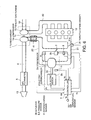
- FIG. 1 is a schematic diagram of an internal combustion engine provided with a supercharging device according to this invention.
- FIG. 2 is a flowchart describing an initial supercharging control routine performed by the controller of this invention.
- FIG. 3 is a diagram describing the operation characteristics of an electric motor used in the electric supercharger according to this invention.
- FIG. 4 is similar to FIG. 1. but showing a second embodiment of this invention.
- FIG. 5 is similar to FIG. 2. but showing the second embodiment of this invention.
- FIG. 6 is a schematic diagram of an internal combustion engine provided with a supercharging device according to a third embodiment of this invention.
- FIG. 7 is a schematic diagram of an electric supercharger according to a fourth embodiment of this invention.
- FIG. 8 is a schematic diagram of an internal combustion engine provided with a supercharging device according to a fifth embodiment of this invention.
- FIG. 9 is a schematic diagram of an internal combustion engine provided with a supercharging device according to a sixth embodiment of this invention.
- FIG. 10 is a flowchart describing an initial supercharging control routine performed by a controller according to a seventh embodiment of this invention.
- FIG. 11 is a flowchart describing a subroutine for calculating a predicted rotation speed NF performed by the controller according to the seventh embodiment of this invention.
- FIG. 12 is a diagram describing the characteristics of a map of a rotation increase rate estimation value ⁇ NMAP stored by the controller according to the seventh embodiment of this invention.
- FIGs. 13A-13E are timing charts describing the starting of an electric motor and the closure timing of a bypass valve according to the seventh embodiment of this invention.
- FIG. 14 is a diagram describing the characteristics of a map of a reference rotation increase rate estimation value ⁇ N0 stored by the controller according to the seventh embodiment of this invention.
- FIG. 15 is a diagram describing the characteristics of a map of a reference current value 10 stored by the controller according to the seventh embodiment of this invention.
- FIG. 16 is a diagram describing the characteristics of a map of a reference voltage value V0 stored by the controller according to the seventh embodiment of this invention.
- FIG. 17 is a diagram describing the characteristics of a rotation speed difference ⁇ N set by a controller according to an eighth embodiment of this invention.
- FIG. 18 is a schematic diagram of an internal combustion engine provided with a supercharging device according to a ninth embodiment of this invention.
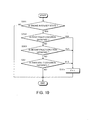
- FIG. 19 is a flowchart describing a fault diagnosis routine in the steady state performed by the controller according to the ninth embodiment of this invention.
- FIG. 20 is a flowchart describing a fault diagnosis routine immediately after stopping supercharging performed by the controller according to the ninth embodiment of this invention.
- FIG. 21 is a flowchart describing a fault processing routine performed by the controller according to the ninth embodiment of this invention.
- FIG. 22 is a flowchart describing a fault processing routine performed by a controller according to a tenth embodiment of this invention.
- an internal combustion engine 12 for a vehicle internally burns a mixture of fuel and air aspirated from intake passages 6, 20, 21, and rotates due to the combustion energy.
- the exhaust gas produced by combustion is discharged from exhaust passages 50, 51.
- the intake passages 6 and 20 are connected via a compressor 1a of a turbocharger 1.
- the exhaust passages 50 and 51 are connected via an exhaust gas turbine 1b of the turbocharger 1.
- the compressor 1a corresponds to a first compressor as defined in the claims.
- the exhaust gas turbine 1b rotates due to the energy of the exhaust gas which flows from the exhaust passage 50, and rotates together with the compressor 1a connected via a shaft 1c.
- the exhaust gas which rotated the exhaust gas turbine 1b flows into the exhaust passage 51.
- the rotating compressor 1a aspirates and pressurizes air from the intake passage 6, and discharges it to the intake passage 20.
- An air cleaner 13 is provided in the intake passage 6.
- Intake passages 20, 21 are connected via a compressor 2a of the electric supercharger 2, and by a bypass passage 7 which bypasses the compressor 2a.
- the compressor 2a corresponds to a second compressor as defined in the claims.
- the electric supercharger 2 is provided with an electric motor 2b which drives the compressor 2a according to a signal from a controller 4, and a shaft 2c which transmits the rotation of the electric motor 2b to the compressor 2a.
- the compressor 2a aspirates and pressurizes the air in the intake passage 20 by rotation of the electric motor 2b, and discharges it to the intake passage 21.
- a throttle 31a is provided in the intake passage 21. The throttle 31a is interlocked with the depression amount of an accelerator pedal with which the vehicle is provided, and changes the intake cross-sectional area of the intake passage 21.
- a bypass valve 3 is provided in the bypass passage 7.
- the bypass valve 3 is driven by an actuator 3b, and opens and closes the bypass passage 7 according to a signal from the controller 4.
- the controller 4 comprises a microcomputer provided with a central processing unit (CPU), read-only memory (ROM), random access memory (RAM) and I/O interface (I/O interface). It is also possible to form the controller from plural microcomputers.
- an air flowmeter 5 which detects an air flowrate Qa of the intake passage 6
- pressure sensor 8 which detects a pressure P1 of the intake passage 20
- pressure sensor 9 which detects a pressure P2 of the intake passage 21
- rotation speed sensor 11 which detects a rotation speed Nc of the compressor 2a
- throttle speed sensor 31 which detects an operating speed Th of the throttle 31a
- air temperature sensor 32 which detects a temperature Ta of the air pressurized by the compressor 2a
- Initial supercharging control specifically means control from starting to stopping of the compressor 2a of the electric supercharger 2.
- Supercharging is performed by the turbocharger 2 during acceleration of the engine 12. This routine aims for supercharging control of the turbo lag period until the boost pressure of the turbocharger 2 reaches the effective pressure from the acceleration requirement.
- the controller 4 determines whether or not acceleration of the engine 12 is required from a throttle operation speed Th inputted from the throttle speed sensor 31. Specifically, it is determined whether or not the throttle operation speed Th exceeds a predetermined value.
- the throttle operation speed Th assumes the speed in the opening direction is a positive value, and assumes the predetermined value is a positive value.
- a typical value of the predetermined value is 30 degrees per 100 milliseconds.
- the throttle speed sensor 31 corresponds to a parameter detection sensor relating to the acceleration requirement of the engine 12.
- the state flag F is a flag showing whether or not the initial supercharging processing has completed regarding the acceleration requirement of the engine 12, and as long as there is no acceleration requirement, it is always maintained at zero. Moreover, it is set to unity when this processing is completed as described hereafter.
- the controller 4 determines whether or not the state flag F is zero in a step S12. When the state flag F is not zero, the routine is terminated without proceeding to further steps. When the state flag F is zero in the step S12, it means that there is an acceleration requirement and the above processing is not complete. In that case, the controller 4, in a step S14, determines whether the compressor 2a is being operated.
- the controller 4 in a step S16, after energizing the electric motor 2b and starting operation of the compressor 2a, terminates the routine.
- the controller 4 determines whether or not the bypass valve 3 is open.
- the controller 4 determines in a step S17 whether or not a flow Qs of air discharged by the compressor 2a of the electric supercharger 2 has reached an air flowrate Qa detected by the air flowmeter 5.
- the air flowrate Qs discharged by the compressor 2a is calculated by the following equation (1) using the rotation speed Nc of the compressor 2a detected by the rotation speed sensor 11, the pressure P1 of the intake passage 20 detected by the pressure sensor 8, and the air temperature Ta of the intake passage 20 detected by the temperature sensor 32.
- Qs COEF ⁇ Nc ⁇ P1 Ta
- COEF conversion factor.
- the air flowrate Qs calculated by equation (1) and the air flowrate Qa detected by the air flowmeter 5 are both mass flowrates.
- All the intake air of the engine 12 passes the air flow meter 5. Therefore, when the air flowrate Qs discharged by the compressor 2a reaches the air flowrate Qa of the air flowmeter 5, it means that all of the intake air passes via the compressor 2a, and the flowrate of the bypass valve 3 is substantially zero. Alternatively, it means that the compressor 2a has reached the rotation speed which is sufficient to satisfy the supercharging required by the engine 12.
- step S17 If the determination of the step S17 is affirmative, the controller 4 closes the bypass valve 3 in a step S19 and terminates the routine. If the determination of the step S17 is negative, the controller 4 terminates the routine immediately without proceeding to the step S19.
- the controller 4 in a step S18, determines whether or not the pressure P1 of the intake passage 20 is more than the pressure P2 of the intake passage 21. When the pressure P1 of the intake passage 21 is less than the pressure P2 of the intake passage 20, the controller 4 terminates the routine immediately.
- the controller 4 opens the bypass valve 3, and in a step S21, stops operation of the compressor 2a, sets the state flag F to unity in the step S21, and terminates the routine.
- the controller 4 After closing the bypass valve 3 in the step S19, the controller 4 continues operation of the compressor 2a until the pressure P1 of the intake passage 20 reaches the pressure P2 of the intake passage 21. If the pressure P1 of the intake passage 20 becomes more than the pressure P2 in the intake passage 21, it means that the boost pressure of the turbocharger 1 has risen and that supercharging can be performed only by the turbocharger 1.
- the controller 4 opens the bypass valve 3, and stops operation of the compressor 2a. Also, the state flag F is set to unity which shows completion of initial supercharging processing. The reason why the bypass valve 3 is closed until the pressure P1 of the intake passage 20 becomes more than the pressure P2 of the intake passage 21 in the step S18, is to prevent air flowing backwards from the intake passage 21 to the intake passage 20 via the bypass valve 3.
- the intake air amount of the engine 12 will decrease and the air-fuel ratio of the fuel-air mixture burnt by the engine 12 or the output torque of the engine 12 will vary.
- the pressure P1 of the intake passage 20 reaches the pressure P2 of the intake passage 21, if the bypass valve 3 is opened, the change-over to the turbocharger 1 from the electric supercharger 2 can be performed smoothly without the air supplied to the engine 12 flowing backwards to the intake passage 20, and affecting exhaust gas composition and output torque.
- step S12 During subsequent acceleration operation of the engine 12, as the determination result of the step S12 becomes negative, essentially none of the processing of this routine is performed, and operation of the engine 12 is performed under supercharging by the turbocharger 1.
- the state flag F is reset to zero in a step S13, and the routine continues resetting the state flag F to zero henceforth at every execution of the routine until an acceleration requirement is detected.
- determination of the acceleration requirement of the engine 12 in the step S11 is performed based on the throttle operation speed Th, but it may also be determined based on the throttle opening or accelerator pedal depression amount.
- the accelerator pedal depression amount is detected by an accelerator pedal depression sensor 56.
- the depression amount is compared with the predetermined amount and when the depression amount is larger than the predetermined amount at a given engine rotation speed in the step S11, the controller 4 determines that the acceleration of the engine 12 is required.
- the predetermined amount depends on the engine rotation speed and is set to, for example, 15 degrees at 1200 revolutions per minute (rpm), 20 degrees at 2000 rpm, and 40 degrees at 3000 rpm.
- the discharge air flowrate Qs of the compressor 2a is calculated by the equation (1) in the step S17, but the air flowrate Qs may also be calculated by another method not based on the equation (1).
- the voltage and current supplied to the electric motor 2b are detected using a voltmeter 33 and an ammeter 34, and the rotation speed of the electric motor 2b is calculated from the voltage and current by looking up a map of the characteristics of the electric motor 2b shown in FIG. 3 which is prestored in the memory (ROM) of the controller 4.
- FIG. 3 shows the relation between the generated torque, rotation speed and generated power of the electric motor 2b to the current and voltage supplied to the electric motor 2b.
- the generated torque increases but the voltage and rotation speed decrease.
- the generated power increases with the current to the vicinity of 300 amperes [A], reaches a maximum near 300 amperes [A], and if the current increases more than this, it starts to decrease.
- the controller 4 calculates the rotation speed Nc of the compressor 2a from the calculated rotation speed of the electric motor 2b. In this embodiment, as the electric motor 2b and compressor 2a are directly connected by the shaft 2c, the rotation speed Nc of the compressor 2a is equal to the rotation speed of the electric motor 2b.
- the controller 4 further calculates the discharge air flowrate Qs of the compressor 2a by the following equation (2) from a discharge flow amount qu per rotation of the compressor 2a which is found beforehand from the specification of the compressor 2a, and the rotation speed Nc of the compressor 2a.
- Qs qu ⁇ Nc
- the rotation speed sensor 11 and the air temperature sensor 32 can be omitted.
- a second air flowmeter 40 which detects a bypass flowrate Qb is installed upstream of the bypass valve 3 of the bypass passage 7.
- the air temperature sensor 32 and the rotation speed sensor 11 of the compressor 2a provided in the first embodiment are omitted in this embodiment.
- the other features of the hardware of the supercharging device are identical to those of the first embodiment.
- the initial supercharging control routine shown in FIG. 5 is performed instead of the initial supercharging control routine of FIG. 2.
- a step S17A is provided instead of the step S17 of FIG. 2.
- step S17A the controller 4 determines whether or not the bypass flowrate Qb is zero.
- the controller 4 closes the bypass valve 3.
- steps S18-S22 the processing of steps S18-S22 is performed.
- the processing other than that of the step S17A is identical to that of the routine of FIG. 2.
- the bypass valve 3 is closed after the bypass flowrate Qb becomes zero after starting the compressor 2a, so even if the bypass valve 3 is closed, the intake air amount of the engine 12 does not change, and reduction of the intake air amount of the engine 12 accompanying closure of the bypass valve 3 can be prevented as in the first embodiment.
- the closure of the bypass valve 3 was delayed until the flowrate of the bypass valve 3 became zero after starting the compressor 2a, but a similar effect can be obtained by delaying closure of the bypass valve 3 to a certain time after starting operation of the compressor 2a, e.g., opening the bypass valve 3 at a predetermined time from the starting of the compressor 2a, or opening the bypass valve 3 when the rotation speed Nc of the compressor 2a reaches a predetermined speed.
- this invention can be applied also to a supercharging device comprising only the compressor 2a and bypass valve 3 as in the above prior art example JP2000-230427A. Moreover, it is not limited to cases where the drive force of the compressor 2a is the electric motor 2b, and can be applied to various rotary drive devices including an exhaust gas turbine.
- the supercharging device is provided with an intercooler 45 between a branch point with the bypass passage 7 of the intake passage 20, and the compressor 1a of the turbocharger 1.
- the remaining features of the construction are identical to those of the supercharging device according to the first or second embodiments. Due to the intercooler 45, air compressed by the compressor 1a which is at a high temperature, is cooled. As a result, as the heat amount transmitted to the electric motor 2b via the shaft 2c from the compressor 2a becomes small, the operating efficiency of the electric motor 2b improves, and the acceleration performance of the supercharging device improves. Also, as the temperature rise of the electric motor 2b is controlled, if the boost pressure of the turbocharger 1 does not rise for example when climbing a mountain road, supercharging by the compressor 2a can be performed over a long period.
- the electric supercharger 2 connects the compressor 2a and electric motor 2b via pulleys 42, 43 and a belt 44 instead of directly connecting via the shaft 2c.
- the pulley 42 is connected to the compressor 2a, and the pulley 43 is connected to the electric motor 2b, respectively, and the belt 44 is looped around the pulleys 42 and 43.
- the remaining features of the construction are identical to those of the third embodiment.
- the amount of heat transfer from the compressor 2a to the electric motor 2b can be further reduced. Also, by setting the outer diameter of the pulley 43 to be larger than the outer diameter of the pulley 42, the rotation of the electric motor 2b can be accelerated and transmitted to the compressor 2a, and the boost pressure of the compressor 2a can be increased.
- a first intercooler 45 is provided between the branch point with the bypass passage 7 of the intake passage 20, and the compressor 2a, and a second intercooler 46 is provided between the branch point of the bypass passage 7 of the intake passage 21, and the engine 12.
- the remaining hardware is identical to that of the first embodiment.
- the air aspirated by the compressor 2b is cooled by the first intercooler 45 as in the third embodiment.
- the heat amount transmitted to the electric motor 2b via the shaft 2c from the compressor 2a becomes small, the operating efficiency of the electric motor 2b improves, and the acceleration performance of the supercharging device improves.
- the temperature rise of the electric motor 2b is controlled, if the boost pressure of the turbocharger 1 does not rise for example when climbing a mountain road, supercharging can be performed by the compressor 2a over a long time period.
- the second intercooler 46 cools both the air discharged from the compressor 2a and the air from the bypass passage 7, and supplies the engine 12, the intake air temperature of the engine 12 is always maintained within a desirable range.
- the first intercooler 45 is disposed between the branch point of the bypass passage 7 of the intake passage, and the compressor 1a of the turbocharger 1.
- the remaining features of the composition are identical to those of the fifth embodiment.
- the air discharged from the compressor 1a passes through the two intercoolers 45 and 46 irrespective-of the operation of the compressor 2a.
- FIGs. 10-12, FIGs. 13A-13E and FIGs 14-16 a seventh embodiment of this invention will be described.
- the bypass valve 3 is closed when the flowrate of the bypass valve 3 is effectively zero.
- a closure signal is outputted to the actuator 3b from the controller 4, and it takes some time for the bypass valve 3 to rotate from a fully open position to a fully closed position.
- This required time introduced a delay into the control of the bypass valve 3. Consequently, as the rotation speed of the electric motor 2b rises during this delay, part of the air discharged from the compressor 2a flows backwards to the intake passage 20 via the bypass valve 3 before it has been closed.
- the bypass valve 3 has completely closed, the intake air volume of the engine 12 rapidly increases, and a stepwise difference may appear in the output torque.
- the main feature of this embodiment is that the rotation speed variation of the electric motor 2b is predicted, and a closure signal is output to the actuator 3b based on the predicted rotation speed so that a stepwise difference does not arise in the output torque of the engine 12 due to closure of the bypass valve 3.
- This routine is also performed at an interval of ten milliseconds during operation of the engine 12.
- step S100 the controller 4 determines whether or not acceleration of the engine 12 is required.
- This determination is identical to the determination of the step S11 of FIG. 2.
- the controller 4 opens the bypass valve 3 in a step S103, stops operation of the compressor 2a in a step S104, and terminates the routine.
- the processing of the Steps S103 and S104 is equivalent to the processing of the Steps S20 and S21 of FIG. 2.
- the controller 4 determines whether or not the compressor 2a is being operated in a step S101.
- This determination is identical to the determination of the step S14 of FIG. 2.
- step S102 the controller 4 energizes the electric motor 2b to start the compressor 2a, and terminates the routine.
- This processing is identical to the processing of the step S16 of FIG. 2.
- the controller 4 determines, in a step S105, whether or not the bypass valve 3 is open. This determination is identical to the determination of the step S15 of FIG. 2.
- a target rotation speed NT of the compressor 2a is calculated from the air flowrate Qa detected by the air flowmeter 5.
- the bypass valve 3 completes the closing operation at the timing where all the intake air of the engine 12 has been supplied from the compressor 2a, or the intake air flowrate Qa has become equal to the discharge flowrate Qs of the compressor 2a.
- the rotation speed Nc of the compressor 2a when the discharge flowrate Qs of the compressor 2a is equal to the intake air volume Qa of the engine 12, is the target rotation speed NT.
- the controller 4 After calculating the target rotation speed NT in the step S106, the controller 4, in a step S107, calculates the predicted rotation speed NF of the compressor 2a after the delay time T has elapsed from the present time by performing the subroutine shown in FIG. 11.
- a step S201 the controller 4 reads the rotation speed Nc of the compressor 2a detected by the rotation speed sensor 11.
- step S202 the controller 4 calculates the difference of the rotation speed Nc of the compressor 2a, and a rotation speed Nc n -1 of the compressor 2a read on the immediately preceding occasion when the subroutine was executed as an increase rate ⁇ Nc of the rotation speed of the compressor 2a.
- step S203 the controller 4 reads a detection voltage V of a voltmeter 33, and a detection current / of an ammeter 34.
- step S204 the controller 4 calculates a rotation increase rate prediction value ⁇ NMAP during the delay time T from the rotation speed Nc of the compressor 2a by looking up a map having the characteristics shown in FIG.12 which is prestored in a memory (ROM).
- the rotation increase rate prediction value ⁇ NMAP becomes smaller as the rotation speed Nc of the compressor 2a increases, as shown in FIG. 12.
- the rotation increase rate per unit time becomes smaller with increasing rotation speed, as shown in FIG. 3.
- the controller 4 corrects the rotation increase rate prediction value ⁇ NMAP by the following equation (4) using a real rotation increase rate ⁇ Nc. This correction corrects for the change of the rotation increase rate of the electric motor 2b due to the effect of the load fluctuation of the electric motor 2b, or the time-dependent variation in the performance of the electric motor 2b.
- the rotation increase rate prediction value after compensation is taken as ⁇ N1.
- the controller 4 performs the calculation of equation (4) after calculating the reference rotation increase rate ⁇ N0 from the rotation speed Nc of the compressor 2a by looking up a map having the characteristics shown in FIG. 14 which is prestored in an internal memory (ROM). This map is set so that the reference rotation increase rate ⁇ N0 decreases as the rotation speed Nc increases.
- the controller 4 further corrects the rotation increase rate prediction value ⁇ N1 by the following equation (5) based on the current I supplied to the electric motor 2b.
- This correction corrects for the variation of the rotation increase rate of the electric motor 2b according to the current /.
- the rotation increase rate prediction value after compensation is taken as ⁇ N2.
- the controller 4 performs the calculation of equation (5) after calculating the reference current value l0 from the rotation speed Nc of the compressor 2a by looking up a map having the characteristics shown in FIG. 15 stored beforehand in the internal- memory (ROM). This map is set so that the reference current value l0 decreases as the rotation speed Nc increases.
- the controller 4 also corrects the rotation increase rate prediction value ⁇ N2 by the following equation (6) based on the voltage V supplied to the electric motor 2b. This corrects the variation of the rotation increase rate prediction value of the electric motor 2b according to the voltage V .
- the rotation increase rate prediction value after correction is set to ⁇ N3.
- the controller 4 performs the calculation of equation (6) after calculating the reference voltage value V0 from the rotation speed Nc of the compressor 2a by looking up a map having the characteristics shown in FIG. 16 stored beforehand in the internal memory (ROM). This map is set so that the reference voltage value V0 increases as the rotation speed Nc increases.
- the predicted rotation speed NF after the delay time T passes is calculated by the following equation (7) using the rotation increase rate prediction value ⁇ N3.
- NF Nc + ⁇ N3 ⁇ T
- the controller 4 terminates the subroutine.
- the controller 4 in a step S108, determines whether or not the predicted rotation speed NF has reached the target rotation speed NT.
- the -controller 4 closes the bypass valve 3 in a step S109, and terminates the routine.
- the controller 4 terminates the routine without performing the processing of the step S109.
- the controller 4 As shown in FIG.13A, if an acceleration requirement is detected in the step S100 at a time t0, the controller 4, as shown in FIG. 13B, immediately switches on power to the electric motor 2b, and starts operation of the compressor 2a.
- the controller 4 outputs a closure signal to the actuator 3b of the bypass valve 3.
- the bypass valve 3 rotates in the closure direction, and at a time t2 when the delay time T has elapsed since the time t1 , the rotation speed Nc of the compressor 2a reaches the target rotation speed NT, and closure of the bypass valve 3 is completed simultaneously.
- closure of the bypass valve 3 since closure of the bypass valve 3 is completed in synchronism with the attainment of the target rotation speed NT by the compressor 2a, the air discharged by the compressor 2a does not flow backwards from the bypass valve 3 to the intake passage 20. Therefore, closure of the bypass valve 3 does not lead to a change in the intake air flowrate of the engine 12, and the output torque of the engine 12 does not vary in stepwise fashion.
- This embodiment is an embodiment relating to a method of calculating the predicted rotation speed NF by the controller 4 in the step S107 of FIG. 8.
- the construction of the hardware of the supercharging device is identical to that of the supercharging device according to the seventh embodiment.
- the rotation speed increase rate of the compressor 2a is fixed.
- the rotation speed difference ⁇ N can be calculated from the delay time T .
- the delay time T can be found beforehand by experiment. Therefore, the rotation speed difference ⁇ N is given as a fixed value.
- the controller 4 according to this embodiment calculates the predicted rotation speed NF by adding the rotation speed difference ⁇ N to the initial value N0 of the rotation speed when the compressor 2a is started.
- the supercharging device is provided with an opening and closing sensor 53 which detects whether the bypass valve 3 is in the closed position, an engine rotation speed sensor 48 which detects the rotation speed Ne of the engine 12, a voltmeter 49 which detects a power generation voltage Vi of an alternator, a SOC sensor 55 which detects a state of charge SOC of a battery, and an accelerator pedal depression sensor 56 which detects a depression amount Acc of an accelerator pedal with which the vehicle is provided.
- the voltmeter 49 detects the voltage Vi as a value representing the generated power of the alternator.
- the throttle speed sensor 31 is also replaced by a throttle opening sensor 54 which detects the opening TVO of the throttle 31a.
- the alternator is an AC generator driven by the engine 12, while the battery stores the generated power of the alternator, and supplies the power to the electric motor 2b.
- the detection data of these sensors are inputted to the controller 4 as signals.
- the remaining hardware of the device is identical to that of the supercharging device of the first embodiment.
- the controller 4 performs the initial supercharging control routine of the first embodiment, second embodiment or seventh embodiment, and diagnoses faults in the bypass valve 3 by performing the routine for fault diagnosis of the bypass valve 3 shown in FIGS. 19 and 20. It also performs the fault processing routine shown in FIG. 21 to ensure that the intake air amount of the engine 12 is not deficient when there is a fault in the bypass valve 3.
- a fault of the bypass valve 3 means that the bypass valve 3 does not move from the closed position.
- FIG. 19 shows the fault diagnosis routine in the steady state. This routine is performed at an interval of ten milliseconds at the same time as the initial supercharging control routine while the engine 12 is operating.
- step S301 the controller 4 determines-whether or not the engine 12 is in a steady state. Specifically, the state where the rotation speed Nc of the compressor 2a detected by the rotation speed sensor 11 is zero continues for a predetermined time, is determined as the steady state. If the state is not the steady state, the controller 4 terminates the routine immediately without performing further processing. In the steady state, in step S302, the controller 4 determines whether or not a first fault condition is satisfied.
- the first fault condition is described below.
- the pressure of the intake passage 21 downstream of the compressor 2a is a highly negative pressure.
- the compressor 2a stops air can hardly pass the compressor 2a or the bypass valve 3 which is fixed in the closed position, so the flow of air from the intake passage 20 to the intake passage 21 will almost be shut off.
- the engine 12 aspirates air in this state the intake passage 21 will go to very high negative pressure. Therefore, in the step S302, it can be determined whether or not this first fault condition is satisfied by determining whether or not the pressure detected by the pressure sensor 9 is less than a preset pressure.
- the present pressure is set to, for example, 10 kilopascals (kPa).
- the controller 4 When the first fault condition is satisfied in the step S302, the controller 4 performs the processing of a step S305.
- the controller 4 determines whether or not a second fault condition is satisfied in a step S303.
- the second fault condition is described below.
- the intake air flowrate Qa detected by the air flowmeter 5 decreases compared to the intake air flowrate of the engine 12 during normal operation which can be found from the opening TVO of the throttle 31a, and the rotation speed Ne of the engine 12. This is because, as air cannot pass either the compressor 2a or the bypass valve 3, the intake air flowrate of the intake passage 6 falls. It can be determined whether or not the second fault condition is satisfied by determining whether or not the intake air flowrate Qa is less than the intake air flowrate of the engine 12 calculated from the opening TVO of throttle 31a, and the rotation speed Ne of the engine 12.
- the controller 4 When the second fault condition is satisfied in the step S303, the controller 4 performs the processing of the step S305. When the second fault condition is not satisfied, the controller 4 determines whether or not a third fault condition is satisfied in a step S304.
- the third fault condition is described below.
- valve 3 When the compressor 2a is not operated, or after a certain time has elapsed after terminating operation of the compressor 2a, even when the controller 4 performs the initial supercharging control routine according to any of the first embodiment, second embodiment or seventh embodiment, the valve 3 must be open as a result of the processing of the step S20 or step S103.
- the controller 4 determines that the third fault condition is satisfied when the signal of the opening and closing sensor 53 continues showing the closed position.
- the controller 4 When the third fault condition is satisfied in the step S304, the controller 4 performs the processing of the step S305.
- the controller 4 will perform the processing of the step S305. When none of the first-third fault conditions is satisfied, the controller 4 terminates the routine without performing anything. In the step S305, the controller 4 sets a fault flag F showing that a fault occurred in the bypass valve 3 to unity, and terminates the routine.
- the fault flag F takes the value of either zero or unity, and its initial value is zero.
- This routine is performed only once when power supply to the electric motor 2a from the controller 4 is stopped.
- the controller 4 determines whether or not the compressor 2a has stopped based on the detection speed Nc of the rotation speed sensor 11. When the compressor 2a has not stopped, fault diagnosis of the bypass valve 3 is difficult, so the controller 4 terminates the routine immediately without performing further processing.
- the controller 4 determines whether or not the first fault condition is satisfied.
- the first fault condition is not satisfied, in a step S403, it is determined whether or not the second fault condition is satisfied.
- the second fault condition is not satisfied, in a step S404, it is determined whether or not the third fault condition is satisfied.
- the first-third fault conditions are identical to the first-third fault conditions of the routine of FIG. 19.
- step S406 the controller 4 sets the fault flag F to unity and terminates the routine.
- step S405 the controller 4 determines whether or not a predetermined time has elapsed since starting execution of the routine. If the predetermined time has not elapsed, the determination of the steps S402-404 is repeated'. If the predetermined time has elapsed in the step S405, the controller 4 terminates the routine.
- the fault diagnosis algorithms of the routine of FIG. 19 and the routine of FIG.20 are identical, and the reason for separating them is as follows. Specifically, whereas according to the steady state routine of FIG. 19, diagnosis is performed periodically, in the routine immediately after supercharging stops of FIG.20, diagnosis is repeated at a shorter interval during a transition period from when the compressor 2a stops until a predetermined time has elapsed. Thus, by separating the routines and shortening the diagnostic interval immediately after the compressor 2a stops, a fault of the bypass valve 3 can be immediately detected.
- the first-third fault conditions are determined, but the order of these determinations can be set arbitrarily. Also, the fault flag F may be set by determining only one or two of the first-third fault conditions.
- the determination of the first fault condition uses the detection pressure of the pressure sensor 9.
- the pressure sensor 9 is a sensor which detects the pressure P2 used for the initial supercharging control routine as mentioned above, and the fault condition can be determined using the existing sensor.
- the detection data from the air flowmeter 5, throttle opening sensor 54 and-engine rotation speed sensor 48 are used. These sensors are generally used for the usual operation control of the engine 12, and the fault condition can be determined using the existing sensors.
- the closed position signal of the bypass valve 3 detected by the opening and closing sensor 53 is used for the closed position signal of the bypass valve 3 detected by the opening and closing sensor 53. This sensor must be provided for fault diagnosis, and as it directly detects whether or not the bypass valve 3 is closed, the fixing of the bypass valve 3 in the closed position can be detected without fail.
- This routine is also performed at an interval of ten milliseconds at the same time as the initial supercharging control routine during operation of the engine 12.
- a step S501 the controller 4 determines whether or not the fault flag F is unity. When the fault flag F is not unity, a fault has not occurred in the bypass valve 3, so the controller 4 terminates the routine immediately without performing further processing.
- the controller 4 determines the state of charge SOC of the battery based on the input signal from the SOC sensor 55. When SOC is more than a predetermined value, the controller 4 performs processing of a step S503.
- the controller 4 determines whether or not the generation voltage Vi of the alternator detected by the ammeter 49 in the step S506 is more than a predetermined voltage. When the generation voltage Vi is more than the predetermined voltage, the controller 4 performs the processing of a step S503.
- the controller 4 determines a target running speed of the vehicle based on the accelerator depression amount Acc detected by the accelerator pedal depression sensor 56.
- the controller 4 After the processing of the step S503, the controller 4 performs the processing of a step S504.
- step S506 when the generation voltage Vi is less than the predetermined voltage in a step S507, the controller 4 determines the target running speed of the vehicle based on the accelerator pedal depression amount Acc detected by the accelerator pedal depression sensor 56. In a following step S508, the controller 4 reduction corrects the target running speed according to the generation voltage Vi . After the processing of the step S508, the controller 4 performs the processing of a step S504.
- the controller 4 supplies power to the electric motor 2b so that an intake air volume corresponding to the target running speed may be realized. After the processing of the step S504, the controller 4 terminates the routine.
- the controller 4 supplies power to the electric motor 2b within a range permitted by the battery capacity or the alternator generation power, and operates the compressor 2a accordingly. In this way, the air amount supplied to the engine 12 is secured so that a running speed corresponding to the accelerator pedal depression may be realized. Therefore, even when the bypass valve 3 is fixed in the closed position, the vehicle can run at a speed corresponding to the accelerator pedal depression.
- the accelerator pedal depression represents the speed intended by the driver of the vehicle.
- the target running speed is reduction corrected, and the power according to the running speed after correction is supplied to the electric motor 2b.
- the target running speed gradually falls.
- This embodiment relates to the fault processing routine, wherein the controller 4 performs the fault processing routine shown in FIG. 22 instead of the fault processing routine shown in FIG. 21.
- the remaining construction of the supercharging device of this embodiment is identical to that of the supercharging device according to the ninth embodiment.
- this routine omits the Steps S502, S503 and steps S506-S508 from the routine of FIG. 21, and replaces the step S504 by a step S604.
- the controller 4 determines whether or the fault determination flag F is unity. When the fault flag F is not unity, the routine is terminated immediately. When the fault flag F is unity, the controller 4 supplies power to the electric motor 2b in the step S604 and operates the compressor 2a.
- the power supplied to the electric motor 2b is a constant value set based on the intake air amount of the engine 12 required for the vehicle to run on its own.
- the electric motor 2b is driven so that an air amount sufficient for the vehicle to run on its own is supplied to the engine 12 regardless of the state of the battery or alternator, or the driver's intention, so the distance which can be run after the bypass valve 3 is fixed in a closed position becomes longer than in the supercharging device according to the ninth embodiment.
- Tokugan 2002-238894 with a filing date of August 20, 2002, Tokugan 2002-338999 with a filing date of November 22, 2002, Tokugan 2003-044794 with a filing date of February 21, 2003, Tokugan 2003-016201 with a filing date of January 24, 2003 and Tokugan 2003-021667 with a filing date of January 30, 2003 in Japan, are hereby incorporated by reference.
- the parameters required for control are detected using sensors, but this invention can be applied to any supercharging device which can perform the claimed control using the claimed parameters regardless of how the parameters are acquired.
Landscapes
- Engineering & Computer Science (AREA)
- Chemical & Material Sciences (AREA)
- Combustion & Propulsion (AREA)
- Mechanical Engineering (AREA)
- General Engineering & Computer Science (AREA)
- Supercharger (AREA)
Applications Claiming Priority (10)
| Application Number | Priority Date | Filing Date | Title |
|---|---|---|---|
| JP2002238894 | 2002-08-20 | ||
| JP2002238894A JP2004076659A (ja) | 2002-08-20 | 2002-08-20 | 過給装置 |
| JP2002338999A JP2004169662A (ja) | 2002-11-22 | 2002-11-22 | 電動過給システム |
| JP2002338999 | 2002-11-22 | ||
| JP2003016201A JP3826887B2 (ja) | 2003-01-24 | 2003-01-24 | 電動過給機構の制御装置 |
| JP2003016201 | 2003-01-24 | ||
| JP2003021667 | 2003-01-30 | ||
| JP2003021667A JP3969314B2 (ja) | 2003-01-30 | 2003-01-30 | 過給装置 |
| JP2003044794A JP2004251248A (ja) | 2003-02-21 | 2003-02-21 | 内燃機関の過給装置 |
| JP2003044794 | 2003-02-21 |
Publications (2)
| Publication Number | Publication Date |
|---|---|
| EP1391595A1 true EP1391595A1 (fr) | 2004-02-25 |
| EP1391595B1 EP1391595B1 (fr) | 2005-11-02 |
Family
ID=31192429
Family Applications (1)
| Application Number | Title | Priority Date | Filing Date |
|---|---|---|---|
| EP03017873A Expired - Fee Related EP1391595B1 (fr) | 2002-08-20 | 2003-08-05 | Surcompresseur pour moteurs à combustion interne |
Country Status (4)
| Country | Link |
|---|---|
| US (1) | US6938420B2 (fr) |
| EP (1) | EP1391595B1 (fr) |
| CN (1) | CN1303312C (fr) |
| DE (1) | DE60302118T2 (fr) |
Cited By (20)
| Publication number | Priority date | Publication date | Assignee | Title |
|---|---|---|---|---|
| EP1464808A1 (fr) * | 2003-04-03 | 2004-10-06 | Toyota Jidosha Kabushiki Kaisha | Appareil et procédé de commande pour moteur à combustion interne |
| US6922995B2 (en) * | 2003-03-27 | 2005-08-02 | Nissan Motor Co., Ltd. | Supercharging device for internal combustion engine |
| WO2005108755A1 (fr) * | 2004-05-07 | 2005-11-17 | Honeywell International Inc. | Procede de fonctionnement d'un turbocompresseur a commande electrique et un dispositif de commande |
| WO2007032157A1 (fr) * | 2005-09-15 | 2007-03-22 | Toyota Jidosha Kabushiki Kaisha | Systeme de suralimentation pour moteur a combustion interne |
| CN103104374A (zh) * | 2012-02-02 | 2013-05-15 | 摩尔动力(北京)技术股份有限公司 | 气缸内燃斯特林发动机 |
| CN103122805A (zh) * | 2012-01-29 | 2013-05-29 | 摩尔动力(北京)技术股份有限公司 | 三类门热气发动机 |
| WO2014083248A1 (fr) * | 2012-11-30 | 2014-06-05 | IFP Energies Nouvelles | Procédé de commande d'un moteur thermique équipé d'une double suralimentation |
| GB2508647A (en) * | 2012-12-07 | 2014-06-11 | Valeo Air Man Uk Ltd | Electric supercharger |
| EP2487356A3 (fr) * | 2011-01-24 | 2014-08-13 | Nissan Motor Co., Ltd | Appareil de diagnostic de pression d'admission de moteur à combustion interne |
| EP2767701A1 (fr) * | 2013-02-19 | 2014-08-20 | The Boeing Company | Système de chargement d'air et procédé pour moteur à combustion interne |
| FR3009144A1 (fr) * | 2013-07-24 | 2015-01-30 | Valeo Sys Controle Moteur Sas | Procede de commande d'un alternateur apte a alimenter electriquement un compresseur electrique configure pour comprimer l'air a l'admission d'un moteur thermique |
| EP2444627A4 (fr) * | 2010-03-18 | 2015-06-03 | Mitsubishi Heavy Ind Ltd | Dispositif de suralimentation électrique |
| US9228487B2 (en) | 2010-06-09 | 2016-01-05 | D. Brown Technik Ag | Supercharger for internal combustion engines |
| WO2016058739A1 (fr) * | 2014-10-15 | 2016-04-21 | Continental Automotive Gmbh | Dispositif de suralimentation pour moteur à combustion interne et procédé de fonctionnement du dispositif de suralimentation |
| CN105626237A (zh) * | 2016-03-11 | 2016-06-01 | 东风商用车有限公司 | 一种电动辅助增压系统及其使用方法 |
| WO2016083004A1 (fr) * | 2014-11-24 | 2016-06-02 | Continental Automotive Gmbh | Dispositif de suralimentation pour moteur à combustion interne et procédé de fonctionnement du dispositif de suralimentation |
| DE102015225926A1 (de) * | 2015-12-18 | 2017-06-22 | Robert Bosch Gmbh | Luftsystem für eine Brennkraftmaschine mit einer mit dem Ansaugkanal thermisch verbundenen Leistungselektronik einer elektrischen Zusatzverdichter-Anordnung |
| EP3409919A4 (fr) * | 2016-03-07 | 2019-04-03 | Mitsubishi Heavy Industries Engine & Turbocharger, Ltd. | Système de moteur, dispositif de commande de système de moteur, procédé de commande de système de moteur et programme |
| EP3084198B1 (fr) * | 2013-12-19 | 2019-12-18 | Valeo Systèmes de Contrôle Moteur | Ensemble comprenant un moteur thermique et un compresseur électrique configuré pour chauffer les gaz d'admission |
| CN111164297A (zh) * | 2017-12-04 | 2020-05-15 | 宝马股份公司 | 内燃机、具有这种内燃机的机动车以及用于运行内燃机的方法 |
Families Citing this family (94)
| Publication number | Priority date | Publication date | Assignee | Title |
|---|---|---|---|---|
| DE10124543A1 (de) * | 2001-05-19 | 2002-11-21 | Bosch Gmbh Robert | Verfahren und Vorrichtung zur Steuerung eines elektrisch betriebenen Laders |
| DE10203974A1 (de) * | 2002-01-31 | 2003-08-14 | Bosch Gmbh Robert | Verfahren und Vorrichtung zur Steuerung eines elektrisch betriebenen Laders |
| ITCE20020009A1 (it) * | 2002-09-30 | 2002-12-30 | Giuseppe Ferraro | Dispositivo a girante palettata reversibile con motore/generatore elettrico "senza spazzole" per la gestione dell'aria di sovralimentazione |
| DE10340142A1 (de) * | 2003-09-01 | 2005-03-31 | Robert Bosch Gmbh | Vorrichtung zur Verdichtung von Verbrennungsluft |
| JP4394947B2 (ja) * | 2003-12-24 | 2010-01-06 | 株式会社豊田自動織機 | 過給機付き内燃機関における過給制御装置 |
| JP4124143B2 (ja) * | 2004-03-04 | 2008-07-23 | トヨタ自動車株式会社 | 電動機付過給機の制御装置 |
| US20060162334A1 (en) * | 2005-01-25 | 2006-07-27 | Mr. Kyle Roesler | Turbo-Hybrid Automobile |
| EP1848882A1 (fr) * | 2005-02-16 | 2007-10-31 | Honeywell International, Inc. | Dispositif de suralimentation et procede de commande du dispositif |
| JP4548142B2 (ja) * | 2005-02-16 | 2010-09-22 | 株式会社デンソー | 過給アシスト制御システム |
| KR100749620B1 (ko) * | 2005-03-02 | 2007-08-14 | 가부시키가이샤 덴소 | 과급기 부착 내연 기관용 제어 장치 |
| JP2006242065A (ja) * | 2005-03-02 | 2006-09-14 | Denso Corp | 過給機付き内燃機関の制御装置 |
| JP4662155B2 (ja) * | 2006-01-10 | 2011-03-30 | 株式会社Ihi | 電動機付過給機の回転バランス修正方法および回転バランス試験装置 |
| JP4859029B2 (ja) * | 2006-03-22 | 2012-01-18 | 本田技研工業株式会社 | モータ保護装置 |
| JP2008019835A (ja) * | 2006-07-14 | 2008-01-31 | Mazda Motor Corp | 過給機付きエンジン |
| JP4760914B2 (ja) * | 2006-12-19 | 2011-08-31 | トヨタ自動車株式会社 | 内燃機関の過給制御システム |
| DE102006060313A1 (de) * | 2006-12-20 | 2008-06-26 | Robert Bosch Gmbh | Verfahren zum Betrieb einer Brennkraftmaschine |
| WO2009026134A2 (fr) * | 2007-08-17 | 2009-02-26 | Borgwarner Inc. | Dispositif d'aide à la suralimentation |
| JP4910981B2 (ja) * | 2007-10-19 | 2012-04-04 | 日産自動車株式会社 | 過給式エンジンの制御装置 |
| DE102007051872B4 (de) * | 2007-10-30 | 2019-01-03 | Robert Bosch Gmbh | Verfahren und Vorrichtung zur Diagnose eines Schubumluftventils einer Brennkraftmaschine mit Verdichter |
| US8794000B2 (en) * | 2007-11-30 | 2014-08-05 | Caterpillar Inc. | Natural gas compression system |
| EP2096277A1 (fr) | 2008-02-27 | 2009-09-02 | MAGNETI MARELLI POWERTRAIN S.p.A. | Moteur à combustion interne suralimenté |
| DE102008031317A1 (de) * | 2008-07-02 | 2010-01-07 | Knorr-Bremse Systeme für Nutzfahrzeuge GmbH | Kompressorsystem mit beschränktem Ansaugladedruck |
| US8347624B2 (en) * | 2009-07-07 | 2013-01-08 | Ford Global Technologies, Llc | Oxidant injection during cold engine start |
| US8371118B2 (en) * | 2009-07-07 | 2013-02-12 | Ford Global Technologies, Llc | Oxidant injection to reduce turbo lag |
| IL199803A (en) | 2009-07-12 | 2012-07-31 | Lv Technologies Ltd | Method and system for enhancing engine performance |
| JP4916554B2 (ja) * | 2010-01-15 | 2012-04-11 | 三菱電機株式会社 | 電動過給機の電源制御装置 |
| DE102010008727A1 (de) | 2010-02-20 | 2011-08-25 | Dr. Ing. h.c. F. Porsche Aktiengesellschaft, 70435 | Aufladeanordnung für einen Verbrennungsmotor und Verfahren zum Betreiben eines Verbrennungsmotors mit einer derartigen Aufladeanordnung |
| DE102010027220B4 (de) | 2010-07-15 | 2021-05-12 | Volkswagen Ag | Verfahren zum Starten einer Brennkraftmaschine |
| KR101234633B1 (ko) * | 2010-09-30 | 2013-02-19 | 현대자동차주식회사 | 터보 랙 개선 장치 |
| KR101294050B1 (ko) * | 2010-09-30 | 2013-08-07 | 현대자동차주식회사 | 터보 랙 개선 장치 |
| DE102010043897B4 (de) * | 2010-11-15 | 2022-12-01 | Robert Bosch Gmbh | Verfahren und Vorrichtung zum Betreiben eines Verbrennungsmotors |
| US8943823B2 (en) * | 2010-11-18 | 2015-02-03 | Caterpillar Inc. | Fluid handling system having dedicated EGR turbo-generator |
| AU2012264789B2 (en) * | 2011-05-30 | 2017-03-30 | Fpt Motorenforschung Ag | Supercharged turbocompound engine apparatus |
| CN202746002U (zh) * | 2011-07-15 | 2013-02-20 | 摩尔动力(北京)技术股份有限公司 | 叶轮压气气体压缩机 |
| KR101326972B1 (ko) * | 2011-12-07 | 2013-11-13 | 현대자동차주식회사 | 밀러 사이클엔진 시스템 및 제어방법 |
| US8925316B2 (en) * | 2012-01-09 | 2015-01-06 | GM Global Technology Operations LLC | Control systems and methods for super turbo-charged engines |
| CN103089485A (zh) * | 2012-01-29 | 2013-05-08 | 摩尔动力(北京)技术股份有限公司 | 三类门热气发动机 |
| JP5303049B1 (ja) * | 2012-03-27 | 2013-10-02 | 三菱電機株式会社 | 電動過給機を備えた内燃機関制御装置 |
| JP5243637B1 (ja) * | 2012-03-29 | 2013-07-24 | 三菱電機株式会社 | 内燃機関システム |
| JP5900611B2 (ja) * | 2012-05-15 | 2016-04-06 | トヨタ自動車株式会社 | ハイブリッド車両の制御装置 |
| WO2013183104A1 (fr) * | 2012-06-04 | 2013-12-12 | トヨタ自動車株式会社 | Unité de commande pour moteurs à combustion interne |
| US9027343B2 (en) * | 2012-06-14 | 2015-05-12 | Ford Global Technologies, Llc | Approach for supplying vacuum via a supercharger |
| BR112014030200B1 (pt) * | 2012-06-20 | 2021-08-03 | Dayco Ip Holdings, Llc | Válvula de fluxo variável e sistema para controlar um sistema de turbocarregador acionado por exaustão |
| FR2995354B1 (fr) * | 2012-09-11 | 2014-09-12 | IFP Energies Nouvelles | Procede de determination d'une pression en amont d'un compresseur pour un moteur equipe d'une double suralimentation |
| GB2508921B (en) * | 2012-12-17 | 2018-08-08 | Valeo Air Man Uk Limited | A compressing device with thermal protection |
| BR102013003562B1 (pt) | 2013-02-15 | 2021-09-21 | Embraco Indústria De Compressores E Soluções Em Refrigeração Ltda | Método de acionamento de válvula semi-controlada e sistema de acionamento de válvula semi-controlada para compressor alternativo de múltipla sucção |
| KR101448777B1 (ko) * | 2013-02-27 | 2014-10-13 | 현대자동차 주식회사 | 차량용 브레이크 부압장치 |
| US9599013B2 (en) | 2013-04-15 | 2017-03-21 | Ford Global Technologies, Llc | Direct manifold boost assist device with throttle body manifold volume isolation |
| US9359940B2 (en) * | 2013-04-15 | 2016-06-07 | Ford Global Technologies, Llc | Direct manifold boost assist device with throttle body manifold volume isolation |
| JP6206163B2 (ja) * | 2013-12-20 | 2017-10-04 | トヨタ自動車株式会社 | 内燃機関の制御システム |
| US9166510B1 (en) * | 2014-04-02 | 2015-10-20 | Hamilton Sundstrand Corporation | Systems utilizing a controllable voltage AC generator system |
| US9291094B2 (en) | 2014-05-05 | 2016-03-22 | Dayco Ip Holdings, Llc | Variable flow valve having metered flow orifice |
| JP6318893B2 (ja) * | 2014-06-16 | 2018-05-09 | 株式会社デンソー | 吸気冷却装置 |
| DE102014212967B4 (de) * | 2014-07-03 | 2022-07-07 | Ford Global Technologies, Llc | Aufgeladene Brennkraftmaschine mit Abgasturbolader und Verfahren zum Betreiben einer derartigen Brennkraftmaschine |
| GB2531309B (en) * | 2014-10-16 | 2019-08-07 | Ford Global Tech Llc | A method of controlling a turbocharged engine |
| US9745906B2 (en) * | 2014-12-10 | 2017-08-29 | Ford Global Technologies, Llc | Methods and system for improving compressor recirculation valve operation |
| CN105736197B (zh) * | 2014-12-11 | 2019-03-05 | 上海汽车集团股份有限公司 | 内燃式发动机进气系统及其控制装置和方法 |
| JP5924716B1 (ja) * | 2015-02-03 | 2016-05-25 | 三菱電機株式会社 | 内燃機関の制御装置 |
| US10655548B2 (en) * | 2015-02-17 | 2020-05-19 | Volvo Truck Corporation | Electric supercharging system and method for controlling electric supercharger |
| JP6104964B2 (ja) * | 2015-02-27 | 2017-03-29 | 三菱重工業株式会社 | エンジンの起動装置、起動方法、起動装置を備えた船舶 |
| DE102015103353A1 (de) * | 2015-03-06 | 2016-09-08 | Dr. Ing. H.C. F. Porsche Aktiengesellschaft | Aufladevorrichtung für eine Brennkraftmaschine |
| US9677481B2 (en) * | 2015-06-16 | 2017-06-13 | Ford Global Technologies, Llc | Methods and systems for boost control |
| KR101755802B1 (ko) * | 2015-07-07 | 2017-07-07 | 현대자동차주식회사 | 마일드 하이브리드 시스템의 배기가스 저감 제어 방법 |
| JP6248993B2 (ja) * | 2015-07-31 | 2017-12-20 | トヨタ自動車株式会社 | 内燃機関の制御装置 |
| US9890691B2 (en) * | 2015-08-19 | 2018-02-13 | Ford Global Technologies, Llc | Method and system to reduce charge air cooler condensation |
| DE102015219337A1 (de) * | 2015-10-07 | 2017-04-13 | Robert Bosch Gmbh | Verfahren und Vorrichtung zum Betreiben einer Antriebsvorrichtung, Antriebsvorrichtung |
| US10208693B2 (en) * | 2015-10-28 | 2019-02-19 | Ford Global Technologies, Llc | Method and system to mitigate throttle degradation |
| US9879620B2 (en) * | 2015-11-10 | 2018-01-30 | Ford Global Technologies, Llc | Vacuum control via a compressor bypass valve in a twin-compressor engine system |
| US9726092B2 (en) * | 2015-11-16 | 2017-08-08 | Ford Global Technologies, Llc | Methods and systems for boost control |
| KR101714265B1 (ko) * | 2015-11-30 | 2017-03-23 | 현대자동차주식회사 | 수퍼차저가 장착된 엔진시스템의 제어방법 |
| US9630611B1 (en) | 2016-02-03 | 2017-04-25 | Toyota Motor Engineering & Manufacturing North America, Inc. | System and method for acceleration event prediction |
| JP6589212B2 (ja) * | 2016-03-07 | 2019-10-16 | 三菱重工エンジン&ターボチャージャ株式会社 | 過給システム、過給システムの制御装置、過給システムの制御方法、およびプログラム |
| DE102016003752B4 (de) * | 2016-03-26 | 2022-06-09 | Audi Ag | Verfahren zum Betreiben einer Antriebseinrichtung eines Kraftfahrzeugs sowie entsprechende Antriebseinrichtung |
| US10024227B2 (en) | 2016-05-20 | 2018-07-17 | Ford Global Technologies, Llc | Method and system for boost pressure control |
| US10024226B2 (en) | 2016-05-20 | 2018-07-17 | Ford Global Technologies, Llc | Method and system for boost pressure control |
| US9890697B2 (en) | 2016-05-20 | 2018-02-13 | Ford Global Technologies, Llc | Method and system for boost pressure control |
| CN107435585B (zh) * | 2016-05-27 | 2020-03-31 | 长城汽车股份有限公司 | 车辆的控制方法、系统及车辆 |
| KR102440581B1 (ko) * | 2016-12-13 | 2022-09-05 | 현대자동차 주식회사 | 엔진 시스템 |
| JP6635066B2 (ja) * | 2017-02-06 | 2020-01-22 | トヨタ自動車株式会社 | ハイブリッド車両 |
| US10202913B2 (en) * | 2017-02-06 | 2019-02-12 | Ford Global Technologies, Llc | Method and system for boosted engine system |
| US10508590B2 (en) * | 2017-02-07 | 2019-12-17 | Kohler Co. | Forced induction engine with electric motor for compressor |
| US10815875B2 (en) | 2017-03-30 | 2020-10-27 | Ford Global Technologies, Llc | Method and system for boosted engine system |
| US10731545B2 (en) | 2017-03-30 | 2020-08-04 | Ford Global Technologies, Llc | Method and system for boosted engine system |
| DE102017207878A1 (de) * | 2017-05-10 | 2018-11-15 | Bayerische Motoren Werke Aktiengesellschaft | Aufladeeinrichtung für eine Verbrennungskraftmaschine eines Kraftfahrzeugs, sowie Verfahren zum Betreiben einer solchen Aufladeeinrichtung |
| DE102017217759B3 (de) * | 2017-10-06 | 2019-03-28 | Ford Global Technologies, Llc | Aufgeladene Brennkraftmaschine mit Abgasturbolader und elektrisch antreibbarem Verdichter |
| US10731577B2 (en) | 2017-12-19 | 2020-08-04 | Ford Global Technologies, Llc | Method and system for a boosted engine |
| KR102588946B1 (ko) * | 2018-05-28 | 2023-10-16 | 현대자동차주식회사 | 차량의 서지 발생 방지방법 |
| US10975789B2 (en) * | 2018-06-06 | 2021-04-13 | Ford Global Technologies, Llc | Systems and methods for expediting engine warming |
| CN108798931B (zh) * | 2018-06-28 | 2020-07-03 | 奇瑞汽车股份有限公司 | 两级增压发动机的控制方法及装置 |
| US11408330B2 (en) * | 2018-06-29 | 2022-08-09 | Volvo Truck Corporation | Method of operating a four stroke internal combustion engine system |
| DE102019202707A1 (de) * | 2019-02-28 | 2020-09-17 | Volkswagen Aktiengesellschaft | Verfahren zum Betreiben eines Verbrennungsmotors, Steuergerät, und elektrisch angetriebene Ladeeinrichtung |
| CN111783247B (zh) * | 2020-06-29 | 2023-06-02 | 燕山大学 | 液压阀控缸系统动力机构与负载轻量化匹配方法及系统 |
| US11719118B2 (en) | 2021-04-14 | 2023-08-08 | Honeywell International Inc. | Air supply system |
| US11519313B1 (en) * | 2021-08-04 | 2022-12-06 | Ford Global Technologies, Llc | Methods and systems for engine exhaust catalyst operations |
Citations (5)
| Publication number | Priority date | Publication date | Assignee | Title |
|---|---|---|---|---|
| US4669269A (en) * | 1985-05-15 | 1987-06-02 | Mtu Motoren- Und Turbinen- Union Friedrichshafen Gmbh | Turbocharged internal combustion engine |
| DE19708721A1 (de) * | 1997-03-04 | 1998-09-17 | Man Nutzfahrzeuge Ag | Aufladesystem für eine luftverdichtende Brennkraftmaschine |
| US6062026A (en) * | 1997-05-30 | 2000-05-16 | Turbodyne Systems, Inc. | Turbocharging systems for internal combustion engines |
| DE19905112A1 (de) * | 1999-02-09 | 2000-08-10 | Fev Motorentech Gmbh | Verfahren zum Betreiben einer Kolbenbrennkraftmaschine mit Vorverdichtung der Verbrennungsluft und Kolbenbrennkraftmaschine zur Durchführung des Verfahrens |
| EP1070837A2 (fr) * | 1999-07-23 | 2001-01-24 | Steyr-Nutzfahrzeuge Aktiengesellschaft | Dispositif et procédé pour augmenter la puissance d'un moteur turbochargé |
Family Cites Families (10)
| Publication number | Priority date | Publication date | Assignee | Title |
|---|---|---|---|---|
| US4930315A (en) * | 1987-05-29 | 1990-06-05 | Usui Kokusai Sangyo Kabushiki Kaisha | Turbo-charger engine system |
| SE467634B (sv) * | 1990-05-15 | 1992-08-17 | Volvo Ab | Anordning vid turboreglering |
| DE4210070C2 (de) * | 1992-03-27 | 1996-10-17 | Daimler Benz Ag | Brennkraftmaschine mit kombinierter Aufladung |
| JP3312411B2 (ja) | 1993-01-11 | 2002-08-05 | いすゞ自動車株式会社 | ターボチャージャ制御装置 |
| US5771868A (en) * | 1997-07-03 | 1998-06-30 | Turbodyne Systems, Inc. | Turbocharging systems for internal combustion engines |
| JP2000230427A (ja) | 1999-02-08 | 2000-08-22 | Denso Corp | 過給機付内燃機関 |
| JP2001280145A (ja) | 2000-03-30 | 2001-10-10 | Nissan Motor Co Ltd | 過給機付きエンジンの制御装置 |
| DE10023022A1 (de) | 2000-05-11 | 2001-11-22 | Borgwarner Inc | Aufgeladene Brennkraftmaschine |
| EP1327753B1 (fr) * | 2001-12-24 | 2004-10-13 | Visteon Global Technologies, Inc. | Systeme de degasage pour un moteur à combustion interne |
| US6755022B2 (en) * | 2002-02-28 | 2004-06-29 | Mack Trucks, Inc. | Turbo-charged internal combustion engine with in-cylinder EGR and injection rate shaping |
-
2003
- 2003-07-22 US US10/623,564 patent/US6938420B2/en not_active Expired - Lifetime
- 2003-08-05 DE DE60302118T patent/DE60302118T2/de not_active Expired - Lifetime
- 2003-08-05 EP EP03017873A patent/EP1391595B1/fr not_active Expired - Fee Related
- 2003-08-19 CN CNB031549691A patent/CN1303312C/zh not_active Expired - Fee Related
Patent Citations (5)
| Publication number | Priority date | Publication date | Assignee | Title |
|---|---|---|---|---|
| US4669269A (en) * | 1985-05-15 | 1987-06-02 | Mtu Motoren- Und Turbinen- Union Friedrichshafen Gmbh | Turbocharged internal combustion engine |
| DE19708721A1 (de) * | 1997-03-04 | 1998-09-17 | Man Nutzfahrzeuge Ag | Aufladesystem für eine luftverdichtende Brennkraftmaschine |
| US6062026A (en) * | 1997-05-30 | 2000-05-16 | Turbodyne Systems, Inc. | Turbocharging systems for internal combustion engines |
| DE19905112A1 (de) * | 1999-02-09 | 2000-08-10 | Fev Motorentech Gmbh | Verfahren zum Betreiben einer Kolbenbrennkraftmaschine mit Vorverdichtung der Verbrennungsluft und Kolbenbrennkraftmaschine zur Durchführung des Verfahrens |
| EP1070837A2 (fr) * | 1999-07-23 | 2001-01-24 | Steyr-Nutzfahrzeuge Aktiengesellschaft | Dispositif et procédé pour augmenter la puissance d'un moteur turbochargé |
Cited By (36)
| Publication number | Priority date | Publication date | Assignee | Title |
|---|---|---|---|---|
| US6922995B2 (en) * | 2003-03-27 | 2005-08-02 | Nissan Motor Co., Ltd. | Supercharging device for internal combustion engine |
| EP1464808A1 (fr) * | 2003-04-03 | 2004-10-06 | Toyota Jidosha Kabushiki Kaisha | Appareil et procédé de commande pour moteur à combustion interne |
| US6883324B2 (en) | 2003-04-03 | 2005-04-26 | Toyota Jidosha Kabushiki Kaisha | Control apparatus and control method for internal combustion engine |
| WO2005108755A1 (fr) * | 2004-05-07 | 2005-11-17 | Honeywell International Inc. | Procede de fonctionnement d'un turbocompresseur a commande electrique et un dispositif de commande |
| US8205450B2 (en) | 2004-05-07 | 2012-06-26 | Honeywell International Inc. | Method of operating an electrically assisted turbocharger and a boosting device |
| WO2007032157A1 (fr) * | 2005-09-15 | 2007-03-22 | Toyota Jidosha Kabushiki Kaisha | Systeme de suralimentation pour moteur a combustion interne |
| US8006495B2 (en) | 2005-09-15 | 2011-08-30 | Toyota Jidosha Kabushiki Kaisha | Supercharging system for internal combustion engine |
| US9328656B2 (en) | 2010-03-18 | 2016-05-03 | Mitsubishi Heavy Industries, Inc. | Electrically driven turbocharger device |
| EP2444627A4 (fr) * | 2010-03-18 | 2015-06-03 | Mitsubishi Heavy Ind Ltd | Dispositif de suralimentation électrique |
| US9228487B2 (en) | 2010-06-09 | 2016-01-05 | D. Brown Technik Ag | Supercharger for internal combustion engines |
| US8924123B2 (en) | 2011-01-24 | 2014-12-30 | Nissan Motor Co., Ltd. | Internal combustion engine boost pressure diagnostic apparatus |
| EP2487356A3 (fr) * | 2011-01-24 | 2014-08-13 | Nissan Motor Co., Ltd | Appareil de diagnostic de pression d'admission de moteur à combustion interne |
| CN103122805A (zh) * | 2012-01-29 | 2013-05-29 | 摩尔动力(北京)技术股份有限公司 | 三类门热气发动机 |
| CN103104374A (zh) * | 2012-02-02 | 2013-05-15 | 摩尔动力(北京)技术股份有限公司 | 气缸内燃斯特林发动机 |
| US10054038B2 (en) | 2012-11-30 | 2018-08-21 | IFP Energies Nouvelles | Method for controlling a dual-supercharged combustion engine |
| FR2998924A1 (fr) * | 2012-11-30 | 2014-06-06 | IFP Energies Nouvelles | Procede de commande d'un moteur thermique equipe d'une double suralimentation |
| WO2014083248A1 (fr) * | 2012-11-30 | 2014-06-05 | IFP Energies Nouvelles | Procédé de commande d'un moteur thermique équipé d'une double suralimentation |
| GB2508647B (en) * | 2012-12-07 | 2017-11-22 | Valeo Air Man Uk Ltd | Electric supercharger with a seal |
| GB2508647A (en) * | 2012-12-07 | 2014-06-11 | Valeo Air Man Uk Ltd | Electric supercharger |
| US9010114B2 (en) | 2013-02-19 | 2015-04-21 | The Boeing Company | Air charge system and method for an internal combustion engine |
| EP2767701A1 (fr) * | 2013-02-19 | 2014-08-20 | The Boeing Company | Système de chargement d'air et procédé pour moteur à combustion interne |
| WO2015011420A3 (fr) * | 2013-07-24 | 2015-06-11 | Valeo Systemes De Controle Moteur | Procede de commande d'un alternateur apte a alimenter electriquement un compresseur electrique configure pour comprimer l'air a l'admission d'un moteur thermique |
| FR3009144A1 (fr) * | 2013-07-24 | 2015-01-30 | Valeo Sys Controle Moteur Sas | Procede de commande d'un alternateur apte a alimenter electriquement un compresseur electrique configure pour comprimer l'air a l'admission d'un moteur thermique |
| EP3084198B1 (fr) * | 2013-12-19 | 2019-12-18 | Valeo Systèmes de Contrôle Moteur | Ensemble comprenant un moteur thermique et un compresseur électrique configuré pour chauffer les gaz d'admission |
| WO2016058739A1 (fr) * | 2014-10-15 | 2016-04-21 | Continental Automotive Gmbh | Dispositif de suralimentation pour moteur à combustion interne et procédé de fonctionnement du dispositif de suralimentation |
| CN106795805A (zh) * | 2014-10-15 | 2017-05-31 | 大陆汽车有限公司 | 用于内燃发动机的增压设备和用于增压设备的操作方法 |
| CN106795805B (zh) * | 2014-10-15 | 2019-06-21 | 大陆汽车有限公司 | 用于内燃发动机的增压设备和用于增压设备的操作方法 |
| US10563572B2 (en) | 2014-10-15 | 2020-02-18 | Vitesco Technologies GmbH | Charging device for an internal combustion engine and operating method for the charging device |
| WO2016083004A1 (fr) * | 2014-11-24 | 2016-06-02 | Continental Automotive Gmbh | Dispositif de suralimentation pour moteur à combustion interne et procédé de fonctionnement du dispositif de suralimentation |
| US10526955B2 (en) | 2014-11-24 | 2020-01-07 | Vitesco Technologies GmbH | Supercharging device for an internal combustion engine, and operating method for the supercharging device |
| DE102015225926A1 (de) * | 2015-12-18 | 2017-06-22 | Robert Bosch Gmbh | Luftsystem für eine Brennkraftmaschine mit einer mit dem Ansaugkanal thermisch verbundenen Leistungselektronik einer elektrischen Zusatzverdichter-Anordnung |
| EP3409919A4 (fr) * | 2016-03-07 | 2019-04-03 | Mitsubishi Heavy Industries Engine & Turbocharger, Ltd. | Système de moteur, dispositif de commande de système de moteur, procédé de commande de système de moteur et programme |
| US10753269B2 (en) | 2016-03-07 | 2020-08-25 | Mitsubishi Heavy Industries Engine & Turbocharger, Ltd. | Engine system, engine system control device, engine system control method, and program |
| CN105626237A (zh) * | 2016-03-11 | 2016-06-01 | 东风商用车有限公司 | 一种电动辅助增压系统及其使用方法 |
| CN111164297A (zh) * | 2017-12-04 | 2020-05-15 | 宝马股份公司 | 内燃机、具有这种内燃机的机动车以及用于运行内燃机的方法 |
| CN111164297B (zh) * | 2017-12-04 | 2022-02-25 | 宝马股份公司 | 内燃机、具有这种内燃机的机动车以及用于运行内燃机的方法 |
Also Published As
| Publication number | Publication date |
|---|---|
| CN1485533A (zh) | 2004-03-31 |
| DE60302118D1 (de) | 2005-12-08 |
| DE60302118T2 (de) | 2006-05-24 |
| EP1391595B1 (fr) | 2005-11-02 |
| US6938420B2 (en) | 2005-09-06 |
| CN1303312C (zh) | 2007-03-07 |
| US20040194466A1 (en) | 2004-10-07 |
Similar Documents
| Publication | Publication Date | Title |
|---|---|---|
| EP1391595B1 (fr) | Surcompresseur pour moteurs à combustion interne | |
| EP1460247B1 (fr) | Dispositif et procédé de controle d'un moteur à combustion interne | |
| US8096123B2 (en) | System and method for mode transition for a two-stage series sequential turbocharger | |
| US7047740B2 (en) | Boost pressure estimation apparatus for internal combustion engine with supercharger | |
| US7793500B2 (en) | Control apparatus for internal combustion engine having motor-driven supercharger | |
| US9267426B2 (en) | Internal combustion engine wastegate valve controller | |
| EP1462629A1 (fr) | Dispositif de suralimentation pour un moteur à combustion interne | |
| EP1464808B1 (fr) | Appareil et procédé de commande pour moteur à combustion interne | |
| US20080053091A1 (en) | Turbocharging Device and Control Method for Controlling the Turbocharging Device | |
| US8813493B2 (en) | Supercharger control device for an internal combustion engine | |
| EP2444628B1 (fr) | Compresseur électrique | |
| JP3846463B2 (ja) | 電動過給装置 | |
| JP4230000B2 (ja) | 内燃機関のターボチャージャ制御装置 | |
| JP3951942B2 (ja) | 電動過給システム | |
| JP3846462B2 (ja) | 電動過給機構のバイパス弁制御装置 | |
| JP2005061243A (ja) | 内燃機関の過給装置 | |
| JPH04191445A (ja) | 過給機付内燃機関の燃料供給制御装置 | |
| JP3988691B2 (ja) | 内燃機関の過給装置 | |
| JP2004108152A (ja) | 過給装置 | |
| JP2001123844A (ja) | 電動過給機の故障検出装置 | |
| JP3826887B2 (ja) | 電動過給機構の制御装置 | |
| JPH08144811A (ja) | 過給機付内燃機関の燃料供給制御装置 | |
| JP2006017053A (ja) | 過給機付き内燃機関の燃料噴射時期制御装置 | |
| JPH08144812A (ja) | 過給機付内燃機関の燃料供給制御装置 | |
| JPH10122020A (ja) | 過給機付エンジンの制御装置 |
Legal Events
| Date | Code | Title | Description |
|---|---|---|---|
| PUAI | Public reference made under article 153(3) epc to a published international application that has entered the european phase |
Free format text: ORIGINAL CODE: 0009012 |
|
| 17P | Request for examination filed |
Effective date: 20030805 |
|
| AK | Designated contracting states |
Kind code of ref document: A1 Designated state(s): AT BE BG CH CY CZ DE DK EE ES FI FR GB GR HU IE IT LI LU MC NL PT RO SE SI SK TR |
|
| AX | Request for extension of the european patent |
Extension state: AL LT LV MK |
|
| 17Q | First examination report despatched |
Effective date: 20040420 |
|
| AKX | Designation fees paid |
Designated state(s): DE FR GB |
|
| GRAP | Despatch of communication of intention to grant a patent |
Free format text: ORIGINAL CODE: EPIDOSNIGR1 |
|
| GRAS | Grant fee paid |
Free format text: ORIGINAL CODE: EPIDOSNIGR3 |
|
| GRAA | (expected) grant |
Free format text: ORIGINAL CODE: 0009210 |
|
| AK | Designated contracting states |
Kind code of ref document: B1 Designated state(s): DE FR GB |
|
| REG | Reference to a national code |
Ref country code: GB Ref legal event code: FG4D |
|
| REF | Corresponds to: |
Ref document number: 60302118 Country of ref document: DE Date of ref document: 20051208 Kind code of ref document: P |
|
| ET | Fr: translation filed | ||
| PLBE | No opposition filed within time limit |
Free format text: ORIGINAL CODE: 0009261 |
|
| STAA | Information on the status of an ep patent application or granted ep patent |
Free format text: STATUS: NO OPPOSITION FILED WITHIN TIME LIMIT |
|
| 26N | No opposition filed |
Effective date: 20060803 |
|
| REG | Reference to a national code |
Ref country code: FR Ref legal event code: PLFP Year of fee payment: 14 |
|
| PGFP | Annual fee paid to national office [announced via postgrant information from national office to epo] |
Ref country code: DE Payment date: 20160802 Year of fee payment: 14 Ref country code: GB Payment date: 20160803 Year of fee payment: 14 |
|
| PGFP | Annual fee paid to national office [announced via postgrant information from national office to epo] |
Ref country code: FR Payment date: 20160712 Year of fee payment: 14 |
|
| REG | Reference to a national code |
Ref country code: DE Ref legal event code: R119 Ref document number: 60302118 Country of ref document: DE |
|
| GBPC | Gb: european patent ceased through non-payment of renewal fee |
Effective date: 20170805 |
|
| REG | Reference to a national code |
Ref country code: FR Ref legal event code: ST Effective date: 20180430 |
|
| PG25 | Lapsed in a contracting state [announced via postgrant information from national office to epo] |
Ref country code: DE Free format text: LAPSE BECAUSE OF NON-PAYMENT OF DUE FEES Effective date: 20180301 Ref country code: GB Free format text: LAPSE BECAUSE OF NON-PAYMENT OF DUE FEES Effective date: 20170805 |
|
| PG25 | Lapsed in a contracting state [announced via postgrant information from national office to epo] |
Ref country code: FR Free format text: LAPSE BECAUSE OF NON-PAYMENT OF DUE FEES Effective date: 20170831 |