EP1391347A2 - Scheinwerfer für Fahrzeuge - Google Patents
Scheinwerfer für Fahrzeuge Download PDFInfo
- Publication number
- EP1391347A2 EP1391347A2 EP03102332A EP03102332A EP1391347A2 EP 1391347 A2 EP1391347 A2 EP 1391347A2 EP 03102332 A EP03102332 A EP 03102332A EP 03102332 A EP03102332 A EP 03102332A EP 1391347 A2 EP1391347 A2 EP 1391347A2
- Authority
- EP
- European Patent Office
- Prior art keywords
- beam module
- low
- module
- coupling element
- headlamp according
- Prior art date
- Legal status (The legal status is an assumption and is not a legal conclusion. Google has not performed a legal analysis and makes no representation as to the accuracy of the status listed.)
- Granted
Links
Images
Classifications
-
- B—PERFORMING OPERATIONS; TRANSPORTING
- B60—VEHICLES IN GENERAL
- B60Q—ARRANGEMENT OF SIGNALLING OR LIGHTING DEVICES, THE MOUNTING OR SUPPORTING THEREOF OR CIRCUITS THEREFOR, FOR VEHICLES IN GENERAL
- B60Q1/00—Arrangement of optical signalling or lighting devices, the mounting or supporting thereof or circuits therefor
- B60Q1/02—Arrangement of optical signalling or lighting devices, the mounting or supporting thereof or circuits therefor the devices being primarily intended to illuminate the way ahead or to illuminate other areas of way or environments
- B60Q1/04—Arrangement of optical signalling or lighting devices, the mounting or supporting thereof or circuits therefor the devices being primarily intended to illuminate the way ahead or to illuminate other areas of way or environments the devices being headlights
- B60Q1/06—Arrangement of optical signalling or lighting devices, the mounting or supporting thereof or circuits therefor the devices being primarily intended to illuminate the way ahead or to illuminate other areas of way or environments the devices being headlights adjustable, e.g. remotely-controlled from inside vehicle
- B60Q1/068—Arrangement of optical signalling or lighting devices, the mounting or supporting thereof or circuits therefor the devices being primarily intended to illuminate the way ahead or to illuminate other areas of way or environments the devices being headlights adjustable, e.g. remotely-controlled from inside vehicle by mechanical means
- B60Q1/0683—Adjustable by rotation of a screw
-
- B—PERFORMING OPERATIONS; TRANSPORTING
- B60—VEHICLES IN GENERAL
- B60Q—ARRANGEMENT OF SIGNALLING OR LIGHTING DEVICES, THE MOUNTING OR SUPPORTING THEREOF OR CIRCUITS THEREFOR, FOR VEHICLES IN GENERAL
- B60Q1/00—Arrangement of optical signalling or lighting devices, the mounting or supporting thereof or circuits therefor
- B60Q1/02—Arrangement of optical signalling or lighting devices, the mounting or supporting thereof or circuits therefor the devices being primarily intended to illuminate the way ahead or to illuminate other areas of way or environments
- B60Q1/04—Arrangement of optical signalling or lighting devices, the mounting or supporting thereof or circuits therefor the devices being primarily intended to illuminate the way ahead or to illuminate other areas of way or environments the devices being headlights
- B60Q1/06—Arrangement of optical signalling or lighting devices, the mounting or supporting thereof or circuits therefor the devices being primarily intended to illuminate the way ahead or to illuminate other areas of way or environments the devices being headlights adjustable, e.g. remotely-controlled from inside vehicle
- B60Q1/08—Arrangement of optical signalling or lighting devices, the mounting or supporting thereof or circuits therefor the devices being primarily intended to illuminate the way ahead or to illuminate other areas of way or environments the devices being headlights adjustable, e.g. remotely-controlled from inside vehicle automatically
- B60Q1/10—Arrangement of optical signalling or lighting devices, the mounting or supporting thereof or circuits therefor the devices being primarily intended to illuminate the way ahead or to illuminate other areas of way or environments the devices being headlights adjustable, e.g. remotely-controlled from inside vehicle automatically due to vehicle inclination, e.g. due to load distribution
-
- B—PERFORMING OPERATIONS; TRANSPORTING
- B60—VEHICLES IN GENERAL
- B60Q—ARRANGEMENT OF SIGNALLING OR LIGHTING DEVICES, THE MOUNTING OR SUPPORTING THEREOF OR CIRCUITS THEREFOR, FOR VEHICLES IN GENERAL
- B60Q1/00—Arrangement of optical signalling or lighting devices, the mounting or supporting thereof or circuits therefor
- B60Q1/02—Arrangement of optical signalling or lighting devices, the mounting or supporting thereof or circuits therefor the devices being primarily intended to illuminate the way ahead or to illuminate other areas of way or environments
- B60Q1/04—Arrangement of optical signalling or lighting devices, the mounting or supporting thereof or circuits therefor the devices being primarily intended to illuminate the way ahead or to illuminate other areas of way or environments the devices being headlights
- B60Q1/06—Arrangement of optical signalling or lighting devices, the mounting or supporting thereof or circuits therefor the devices being primarily intended to illuminate the way ahead or to illuminate other areas of way or environments the devices being headlights adjustable, e.g. remotely-controlled from inside vehicle
- B60Q1/08—Arrangement of optical signalling or lighting devices, the mounting or supporting thereof or circuits therefor the devices being primarily intended to illuminate the way ahead or to illuminate other areas of way or environments the devices being headlights adjustable, e.g. remotely-controlled from inside vehicle automatically
- B60Q1/12—Arrangement of optical signalling or lighting devices, the mounting or supporting thereof or circuits therefor the devices being primarily intended to illuminate the way ahead or to illuminate other areas of way or environments the devices being headlights adjustable, e.g. remotely-controlled from inside vehicle automatically due to steering position
-
- B—PERFORMING OPERATIONS; TRANSPORTING
- B60—VEHICLES IN GENERAL
- B60Q—ARRANGEMENT OF SIGNALLING OR LIGHTING DEVICES, THE MOUNTING OR SUPPORTING THEREOF OR CIRCUITS THEREFOR, FOR VEHICLES IN GENERAL
- B60Q2200/00—Special features or arrangements of vehicle headlamps
- B60Q2200/30—Special arrangements for adjusting headlamps, e.g. means for transmitting the movements for adjusting the lamps
- B60Q2200/36—Conjoint adjustments, i.e. a mechanical link allows conjoint adjustment of several units
Definitions
- the invention relates to a headlamp for vehicles with a housing, with a arranged inside the housing Abblertzt- and a High beam module, with adjustment devices for the dipped beam module and the High beam module through which the low beam module for basic adjustment a horizontal and vertical axis swiveling and the high beam module for Adjustment is pivotable about a horizontal axis, and with an intermediate Abblertzt- and high beam module extending coupling element, between the and the low beam and high beam module each have a hinged connection consists, through which the high beam module when pivoting the Dipped beam module about its horizontal axis about a horizontal axis mitschwenkt.
- Such a headlamp for vehicles is known from DE-U-20202442.
- the headlight has a housing made of plastic, whose front is closed by a translucent lens is. Inside the housing is a low beam and a high beam module arranged.
- As dipped beam module is a projection module and as a high beam module, a cup-shaped reflector for high beam.
- the fronts of the low beam and high beam modules are in the light exit direction to each other staggered.
- the support frame of the dipped beam module and the cup-shaped Reflectors are connected by a coupling element.
- As a coupling element serves a guide piece, which cooperates with guide surfaces of the housing and is supported vertically by the guide surfaces.
- the leader in turn holds a egg nstellvorraum formed by a headlamp leveler, the with the lower portion of the support frame of the dipped beam module articulated is connected.
- the leader again holds over the headlamp leveler the low beam module.
- the headlamp leveler is the dipped beam module pivotable about a horizontal axis.
- the horizontal one Axis is defined by two between the top of the support frame and the housing existing pivot bearing.
- a pivot bearing is stationary executed while the other pivot bearing to a manual adjustment device belongs.
- the low beam module is to a vertical axis pivoting from the articulated connection between the headlamp leveler and the fixed pivot bearing is formed and the extends adjacent to the cup-shaped reflector.
- the cup-shaped Reflector is at its upper area via two pivot bearings with the housing connected.
- the two pivot bearings are each with a manual Adjustment device coupled and define a horizontal axis.
- the guide piece is articulated with connected to the reflector.
- the guide piece is together with the headlight lust through a manual adjustment device, one with the housing having connected adjusting screw, in or against the light exit direction of the headlamp displaceable.
- the dipped beam module is common with the high beam module around one horizontal axis manually pivotable.
- the two manual adjusters of the high beam module are used to adjust the high beam module relative to the low beam module.
- the leader which is the high beam module with the low beam module coupled, must be large in size and slidable in a guide of the housing and be supported as it is the one formed by the headlamp leveler Adjustment and the low beam module contributes. Furthermore, because of the large extent of the guide piece forgiven and is then only sluggishly slidable in the guide of the housing.
- a headlamp for vehicles in which a low-beam module is arranged inside the headlight is that by an adjustment device formed by a headlamp leveling is pivotable about a horizontal axis. Laterally next to the low beam module is arranged in the housing a distance measuring unit. The distance measuring unit is on the housing about two pivot bearings about a horizontal axis pivotable.
- the low-beam module and the distance measuring unit are characterized by a coupling element connected together. As a coupling element serves a joint element, the articulated with the low beam module and the distance measuring unit connected is. As a result, the low-beam module and the distance measuring unit together by one horizontal axis through the headlamp leveler pivotable.
- the joint element consists of a threaded bolt, engages in a mounted on the distance measuring unit nut and is mounted with a ball head articulated to the low beam module.
- the distance measuring unit is adjustable relative to the dipped beam.
- the adjustment device consists of many parts and only by awkward by a closable by a lid housing opening is accessible through. Furthermore, can be the common adjustment of low-beam module and distance measuring unit with the adjusting device move and thus adjust automatically.
- the object of the invention is described in the preamble of claim 1 To improve headlights for vehicles such that all settings from the low beam and high beam module of the coupling element functionally reliable are feasible.
- This object is achieved according to the invention characterized that all adjustment devices for the low beam and the high beam module exist between them and the housing of the headlamp and the Coupling element is a joint element of a joint device and exclusively at articulated connections of the low and high beam module is held.
- the adjusting device for adjusting the high-beam module, by the high beam module is pivotable about a horizontal axis, so can be designed to be simple and easy from the outside of the housing is easily accessible.
- the headlamp leveler and the adjustment the high-beam module adjusting device regardless of the coupling element and the coupling element without regard to the headlamp leveling and the adjusting device for adjusting the high-beam module be dimensioned and designed.
- the coupling element is inexpensive to produce, if it is rod-shaped and a one-piece component.
- the coupling element in the light exit direction staggered front sides of the Abbleriumt- and High beam module, at least in one section between the front sides runs, and the articulated connections of the hinge device to the arranged adjacent edge regions of the low and high beam module are.
- the coupling element builds as short as possible and a misalignment the high beam module by an extension of the coupling element as a result of a large temperature increase in the headlight interior is very small and therefore no longer disturbing.
- it continues advantageous if it is along a plane extending in the light exit direction vertical plane runs and the articulated connections at the front and rear End portion of the coupling element are arranged. This is due to the articulated connections of the coupling element during joint adjustment of low beam module and high beam module no jamming and jamming the coupling element possible.
- Another advantage is when a hinged connection adjacent to a hinge point of the adjustment device through which the low beam module is pivotable about the horizontal axis, arranged on the low-beam module is.
- a hinged connection adjacent to a hinge point of the adjustment device through which the low beam module is pivotable about the horizontal axis, arranged on the low-beam module is.
- the hinge device is inexpensive to produce and the coupling element is easy and quick to install, if the hinged connections of a Bearing journal and a bearing opening are formed, the pivot axis runs transversely to the Lichtaustrittides the headlamp, and the journals and bearing openings of integral with components of the dipped beam module or High beam module executed joint parts are formed.
- the vertical axis for the low beam module is defined by hinge points which are arranged on the low beam module adjacent to the high beam module and exist between the low beam module and the housing.
- the side of the low beam module, which holds the high beam module via the coupling element, is held securely against the vibrations occurring during driving.
- the adjusting device associated with the low-beam module by which the low-beam module and the high-beam module are pivotable together about horizontal axes, has an adjusting device for basic adjustment of the low beam and high beam module and an automatic headlight range control.
- the headlamp range of the low-beam module and the high-beam module is adjustable in both the basic setting and by the automatic headlamp leveling controller.
- the adjustment for basic adjustment can be done manually or automatically by the headlamp leveler.
- the high beam module is a cup-shaped Reflector and the dipped beam module is a swivel module for cornering light, wherein a hinged connection of the coupling element of a Curved light module surrounding frame is formed. Because of the big ones Mass of a cornering light module be stable to support serving frame is executed, is also the relatively light high beam module via the coupling element securely held against vibrations.
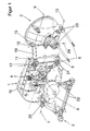
- Figure 1 is a perspective view of a first headlight for Vehicles in which a low beam and a high beam module are common by adjusting both manually and automatically by horizontal Axles are swiveled, and
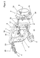
- Figure 2 is a perspective view of a second headlight for Vehicles in which a low beam and a high beam module are common manually pivotable about horizontal axes by an adjustment device are and only the dipped beam module by a headlamp leveler is automatically pivotable about a horizontal axis.
- the first headlamp ( Figure 1) for vehicles has a low beam module 1 and a high beam module 2, which in a housing, not shown are arranged.
- the front sides 18 and 19 of the low beam and High-beam module 1 and 2 are offset in the light exit direction to each other arranged.
- Of the low beam module 1 is only an outer frame 16th shown.
- Swivel module used, which for cornering light around a vertical Axis is pivotable.
- the frame 16 is over three hinge points 17, 20 and 21 connected to the housing.
- the two pivot points 17 and 21 are in the corner regions of the high-beam module 2 near the edge region arranged the frame 16 and define a vertical axis 8.
- the adjusting device 3 is on the housing supported and has a gear assembly 22 through which an adjustment of the low-beam module 1 from the upper side of the housing is possible.
- the hinge point 20 is at an outer lower corner area the frame 16 and the hinge point 21 at the inner lower corner region the frame 16 is arranged. Define the two hinge points 20 and 21 a horizontal axis 7 around which the low-beam module 1 by a the upper hinge point 17 associated adjusting device 4/5 pivotally is.
- the adjusting device 4/5 is composed of one of a Manual adjusting device formed adjusting device 4 and a Adjustment device formed by an automatic headlight leveler 5.
- the adjusting device 5 is supported on the housing while the adjusting device 4 between the adjusting device 5 and the hinge point 17th is arranged.
- the high beam module 2 is opposite the low beam module 1 offset to the front.
- As the high beam module 2 is used Plastic existing cup-shaped reflector.
- the adjusting device 6 consists of two on the housing retained adjustment screws.
- the high beam module 2 is with the low beam module 1 connected by a coupling element 10.
- the coupling element 10 is made in one piece from plastic and executed rod-shaped. Between the free end portions of the coupling element 10 and the Abbleriumt- and high beam module 1 and 2 each have a hinged connection 11 or 12.
- the articulated connection 11 is near the hinge point 17 and the articulated connection 12 in the frame 16 adjacent arranged above the upper edge region of the high-beam light module 2.
- the articulated connection 11 and 12 consist of a journal and a bearing opening (not shown).
- the journal has a crowned On lateral surface, is slotted in its longitudinal extent and indicates its two free end portions each have a latching lug, which is the bearing opening automatically engages behind.
- the bearing openings are in an outer Wall of the frame 16 introduced.
- the two on the housing supported adjusting screws of the adjusting device 6 are from the outside the housing easy and easy to access and pivot the high beam module with simultaneous actuation about the horizontal axis 9, which is defined by the articulated connection 12. That's it High beam module 2 relative to the low beam module 1 adjustable.
- the outer one Adjustment screw of the adjustment device 6 thus serves the basic setting of the high beam module 2.
- the distance of the articulated connection 11 to the horizontal axis 7 of the dipped beam module 1 and the distance of articulated connection 12 to the horizontal axis of the 13 of the high beam module 2 are the same size.
- the second headlight differs from the first Headlight ( Figure 1) by features described below.
- the automatic Headlight range adjuster 5 is the lower hinge point 21 is assigned and the hinge point 20 is in the outer upper Corner of the frame 16 is arranged. This pivots the Headlight range adjuster 5 only the low beam module 1 about a horizontal axis 25 passing through the upper hinge points 17 and 20 passes. When manually adjusting the dipped beam module 1 by the adjustment 4 this gives to the horizontal Axis 7, which passes only through the lower hinge point 21.
- the Adjusting device 4 is the hinge points with one adjusting screw each 17 and 20 assigned.
Landscapes
- Engineering & Computer Science (AREA)
- Mechanical Engineering (AREA)
- Lighting Device Outwards From Vehicle And Optical Signal (AREA)
- Non-Portable Lighting Devices Or Systems Thereof (AREA)
Abstract
Description
Bei einer besonders vorteilhaften Weiterbildung der Erfindung weist die dem Abblendlichtmodul zugeordnete Einstellvorrichtung, durch die das Abblendlichtmodul und das Fernlichtmodul gemeinsam um horizontale Achsen schwenkbar sind, eine Verstelleinrichtung zur Grundeinstellung des Abblendlicht- und Fernlichtmoduls und einen automatischen Leuchtweiteregler auf. Dadurch ist die Leuchtweite des Abblendlichtmoduls und des Fernlichtmoduls gemeinsam sowohl zur Grundeinstellung als auch durch den automatischen Leuchtweiteregler verstellbar. Die Verstelleinrichtung zur Grundeinstellung kann manuell oder automatisch durch den Leuchtweiteregler erfolgen.
- 1.
- Abblendlichtmodul
- 2.
- Fernlichtmodul
- 3.
- Einstellvorrichtung
- 4.
- Einstellvorrichtung
- 5.
- Einstellvorrichtung
- 6.
- Einstellvorrichtung
- 7.
- horizontale Achse
- 8.
- vertikale Achse
- 9.
- horizontale Achse
- 10.
- Koppelelement
- 11.
- gelenkartige Verbindung
- 12.
- gelenkartige Verbindung
- 13.
- horizontale Achse
- 14.
- Gelenkvorrichtung
- 15.
- Bauteil
- 16.
- Rahmen
- 17.
- Gelenkpunkt
- 18.
- Vorderseite
- 19.
- Vorderseite
- 20.
- Gelenkpunkt
- 21.
- Gelenkpunkt
- 22.
- Getriebeanordnung
- 23.
- Gelenkpunkt
- 24.
- vertikale Achse
- 25.
- horizontale Achse
Claims (14)
- Scheinwerfer für Fahrzeugedadurch gekennzeichnet, dassmit einem Gehäuse,mit einem im Inneren des Gehäuses angeordneten Abblendlichtund einem Fernlichtmodul (1 und 2),mit Einstellvorrichtungen (3, 4, 5 und 6) für das Abblendlicht- und Fernlichtmodul (1 und 2), durch welche das Abblendlichtmodul (1) zur Grundeinstellung um eine horizontale und vertikale Achse (7 und 8) schwenkbar und das Fernlichtmodul (2) zur Justierung um eine horizontale Achse (9) schwenkbar ist, undmit einem zwischen Abblendlicht- und Fernlichtmodul (1 und 2) verlaufenden Koppelelement (10), zwischen dem und dem Abblendlicht- und Fernlichtmodul (1 und 2) jeweils eine gelenkartige Verbindung (11 und 12) besteht, durch welches das Fernlichtmodul (2) bei einem Schwenken des Abblendlichtmoduls um seine horizontale Achse (7) um eine horizontale Achse (13) mitschwenkt,alle Einstellvorrichtungen (3, 4, 5 und 6) für das Abblendlicht- und das Fernlichtmodul (1 und 2) zwischen denselben und dem Gehäuse des Scheinwerfers bestehen unddas Koppelelement (10) ein Gelenkelement einer Gelenkvorrichtung (14) ist und ausschließlich an den gelenkartigen Verbindungen (11 und 12) des Abblendlicht- und Fernlichtmoduls (1und 2) gehalten ist.
- Scheinwerfer nach Anspruch 1, dadurch gekennzeichnet, dass das Koppelelement der Gelenkvorrichtung (14) stangenförmig ausgeführt und ein einstückiges Bauteil ist.
- Scheinwerfer nach Anspruch 1 oder 2, dadurch gekennzeichnet, dass das Koppelelement (10), bei in Lichtaustrittsrichtung versetzt zueinander angeordneten Vorderseiten (18 und 19) des Abblendlicht- und Fernlichtmoduls (1 und 2), mindestens mit einem Abschnitt zwischen den Vorderseiten (18 und 19) verläuft.
- Scheinwerfer nach einem der Ansprüche 1 bis 3, dadurch gekennzeichnet, dass das stangenartige Koppelelement (10) entlang einer in Lichtaustrittsrichtung verlaufenden Vertikalebene verläuft und die gelenkartigen Verbindungen (11 und 12) am vorderen und hinteren Endabschnitt des Koppelelements (10) angeordnet sind.
- Scheinwerfer nach einem der Ansprüche 1 bis 4, dadurch gekennzeichnet, dass eine gelenkartige Verbindung (11) benachbart zu einem Gelenkpunkt (17) der Einstellvorrichtung (4), durch die das Abblendlichtmodul (1) um die horizontale Achse (7) schwenkbar ist, an dem Abblendlichtmodul (1) angeordnet ist.
- Scheinwerfer nach Anspruch 5, dadurch gekennzeichnet, dass eine Schwenkachse der gelenkartigen Verbindung (11) durch den Gelenkpunkt (17) hindurchgeht.
- Scheinwerfer nach Anspruch 5 oder 6, dadurch gekennzeichnet, dass der die gelenkartige Verbindung (11) von dem Gelenkpunkt (17) gebildet ist.
- Scheinwerfer nach einem der Ansprüche 1 bis 7, dadurch gekennzeichnet, dass die gelenkartigen Verbindungen (11 und 12) von einem Lagerzapfen und einer Lageröffnung gebildet sind, deren Schwenkachse quer zur Lichtaustrittrichtung des Scheinwerfers verläuft.
- Scheinwerfer nach einem der Ansprüche 1 bis 8, dadurch gekennzeichnet, dass die Lagerzapfen und Lageröffnungen von einstückig mit Bauteilen (15) des Abblendlichtmoduls (1) bzw. Fernlichtmoduls (2) ausgeführten Gelenkteilen gebildet sind.
- Scheinwerfer nach einem der Ansprüche 1 bis 9, dadurch gekennzeichnet, dass die vertikale Achse (8) für das Abblendlichtmodul (1) durch Gelenkpunkte (16) definiert ist, die am Abblendlichtmodul (1) benachbart zum Fernlichtmodul (2) angeordnet sind und zwischen dem Abblendlichtmodul (1) und dem Gehäuse bestehen.
- Scheinwerfer nach einem der Ansprüche 1 bis 10, dadurch geken n-zeichnet, dass die dem Abblendlichtmodul (1) zugeordnete Einstellvorrichtung (4/5), durch die das Abblendlichtmodul (1) und das Fernlichtmodul (2) um horizontale Achsen (7 und 13) und gemeinsam schwenkbar sind, eine Verstelleinrichtung (4) zur Grundeinstellung des Abblendlicht- und Fernlichtmoduls (1 und 2) aufweist.
- Scheinwerfer nach Anspruch 11, dadurch gekennzeichnet, dass die dem Abblendlichtmodul (1) zugeordnete Einstellvorrichtung (4/5), durch die das Abblendlicht- und Fernlichtmodul (1 und 2) um horizontale Achsen (7 und 13) schwenkbar sind, einen automatischen Leuchtweiteregler (5) aufweist.
- Scheinwerfer nach einem der Ansprüche 1 bis 12, dadurch gekennzeichnet, dass das Fernlichtmodul (2) ein schalenförmiger Reflektor und das Abblendlichtmodul (1) ein Schwenkmodul für Kurvenlicht ist, wobei eine gelenkartige Verbindung (11) des Koppelelements (10) an einem das Kurvenlichtmodul umgebenden Rahmen (16) angeordnet ist.
- Scheinwerfer nach einem der Ansprüche 1 bis 13, dadurch gekennzeichnet, dass die Einstellvorrichtung (6) für das Fernlichtmodul (2) von der Außenseite des Gehäuses her zugänglich ist.
Applications Claiming Priority (2)
| Application Number | Priority Date | Filing Date | Title |
|---|---|---|---|
| DE10238792 | 2002-08-23 | ||
| DE2002138792 DE10238792A1 (de) | 2002-08-23 | 2002-08-23 | Scheinwerfer für Fahrzeuge |
Publications (3)
| Publication Number | Publication Date |
|---|---|
| EP1391347A2 true EP1391347A2 (de) | 2004-02-25 |
| EP1391347A3 EP1391347A3 (de) | 2006-05-17 |
| EP1391347B1 EP1391347B1 (de) | 2008-04-23 |
Family
ID=30775541
Family Applications (1)
| Application Number | Title | Priority Date | Filing Date |
|---|---|---|---|
| EP20030102332 Expired - Lifetime EP1391347B1 (de) | 2002-08-23 | 2003-07-29 | Scheinwerfer für Fahrzeuge |
Country Status (3)
| Country | Link |
|---|---|
| EP (1) | EP1391347B1 (de) |
| DE (2) | DE10238792A1 (de) |
| ES (1) | ES2305403T3 (de) |
Cited By (7)
| Publication number | Priority date | Publication date | Assignee | Title |
|---|---|---|---|---|
| DE102004061483A1 (de) * | 2004-12-21 | 2006-06-29 | Hella Kgaa Hueck & Co. | Scheinwerfer für Fahrzeuge |
| EP2112021A1 (de) * | 2008-04-25 | 2009-10-28 | Hella KG Hueck & Co. | Scheinwerfer für Fahrzeuge |
| EP2394850A1 (de) * | 2010-06-10 | 2011-12-14 | Valeo Vision | Gemeinsames manuell betätigbares Verstellsystem für zwei Beleuchtungsvorrichtungen, von denen eine automatisch verstellt werden kann |
| CN104110629A (zh) * | 2013-04-22 | 2014-10-22 | 汽车照明罗伊特林根有限公司 | 机动车前照灯 |
| AT515451A1 (de) * | 2014-03-10 | 2015-09-15 | Zizala Lichtsysteme Gmbh | Einstellvorrichtung für einen Fahrzeugscheinwerfer |
| US9157594B2 (en) * | 2012-12-20 | 2015-10-13 | Hella Kgaa Hueck & Co. | Adjusting device for headlights |
| CN104986098A (zh) * | 2015-06-24 | 2015-10-21 | 华晨汽车集团控股有限公司 | 一种前照灯纵向调节机构 |
Families Citing this family (16)
| Publication number | Priority date | Publication date | Assignee | Title |
|---|---|---|---|---|
| DE10325331B4 (de) * | 2003-06-04 | 2005-09-01 | Automotive Lighting Reutlingen Gmbh | Scheinwerfer |
| DE102005024375B4 (de) | 2005-05-27 | 2022-09-22 | HELLA GmbH & Co. KGaA | Scheinwerfer für Fahrzeuge |
| DE102006018305B4 (de) * | 2006-04-20 | 2012-02-02 | Hella Kgaa Hueck & Co. | Scheinwerfer für Fahrzeuge |
| DE102009033910B4 (de) | 2009-07-20 | 2020-07-02 | Automotive Lighting Reutlingen Gmbh | Beleuchtungseinrichtung für ein Kraftfahrzeug |
| DE102010018730A1 (de) | 2010-04-29 | 2011-11-03 | Hella Kgaa Hueck & Co. | Scheinwerfer für Fahrzeuge |
| DE102010061105A1 (de) | 2010-12-08 | 2012-06-14 | Hella Kgaa Hueck & Co. | Scheinwerfer für ein Fahrzeug mit einer Justageverbingung zwischen zwei Lichteinheiten |
| DE102010061437B4 (de) | 2010-12-21 | 2022-11-03 | HELLA GmbH & Co. KGaA | Einstellvorrichtung für Scheinwerfer |
| DE102010061428A1 (de) | 2010-12-21 | 2012-06-21 | Hella Kgaa Hueck & Co. | Einstellvorrichtung für Scheinwerfer |
| DE102011051681B4 (de) | 2011-07-08 | 2023-09-28 | HELLA GmbH & Co. KGaA | Einstellvorrichtung für Scheinwerfer |
| EP2773530A1 (de) | 2011-10-31 | 2014-09-10 | Hella KGaA Hueck & Co | Einstellvorrichtung für scheinwerfer |
| AT514402B1 (de) * | 2013-05-16 | 2015-09-15 | Zizala Lichtsysteme Gmbh | Fahrzeugscheinwerfer |
| DE102014100727B4 (de) | 2014-01-23 | 2023-09-21 | HELLA GmbH & Co. KGaA | Verfahren zur Grundeinstellung eines Scheinwerfers |
| DE102014007865A1 (de) * | 2014-06-03 | 2015-12-03 | Dr. Ing. H.C. F. Porsche Ag | Fahrzeugscheinwerfer |
| AT517393B1 (de) | 2015-06-19 | 2017-04-15 | Zkw Group Gmbh | Fahrzeugscheinwerfer mit einstellbaren Baueinheiten |
| DE102016117552A1 (de) | 2016-09-19 | 2018-03-22 | HELLA GmbH & Co. KGaA | Drehlager zur drehbaren Aufnahme eines Lichtmoduls in einem Tragrahmen eines Scheinwerfers |
| EP3647113B1 (de) | 2018-10-29 | 2022-04-13 | Valeo Vision | Beleuchtungsvorrichtung für fahrzeug mit einstellung der optischen achse |
Citations (4)
| Publication number | Priority date | Publication date | Assignee | Title |
|---|---|---|---|---|
| FR2424157A1 (fr) * | 1978-04-27 | 1979-11-23 | Cibie Projecteurs | Systeme de reglage d'orientation des reflecteurs d'un projecteur d'automobile |
| EP0081399A1 (de) * | 1981-11-26 | 1983-06-15 | DUCELLIER & Cie | Vorrichtung zum Einstellen der Neigung der Scheinwerfer eines Kraftfahrzeugs |
| EP1120310A2 (de) * | 2000-01-25 | 2001-08-01 | Hella KG Hueck & Co. | Scheinwerferbaugruppe für ein Kraftfahrzeug |
| DE10045943A1 (de) * | 2000-09-16 | 2002-03-28 | Volkswagen Ag | Vorrichtung zum Verstellen einer Scheinwerfereinheit |
Family Cites Families (10)
| Publication number | Priority date | Publication date | Assignee | Title |
|---|---|---|---|---|
| DE2351640A1 (de) * | 1973-10-15 | 1975-04-24 | Bosch Gmbh Robert | Vorrichtung zur regelung der leuchtweite von scheinwerfern |
| DE3703129A1 (de) * | 1987-02-03 | 1988-08-11 | Hella Kg Hueck & Co | Scheinwerfereinheit fuer fahrzeuge |
| JPH0782761B2 (ja) * | 1990-09-26 | 1995-09-06 | 株式会社小糸製作所 | クリアランスランプ一体型自動車用ヘッドランプ |
| DE4133527C2 (de) * | 1991-10-10 | 2001-05-10 | Bosch Gmbh Robert | Scheinwerfer für Kraftfahrzeuge |
| DE4341234C2 (de) * | 1993-12-03 | 2002-09-12 | Bosch Gmbh Robert | Beleuchtungseinrichtung für Fahrzeuge |
| DE19730413C2 (de) * | 1997-07-16 | 2000-02-03 | Porsche Ag | Scheinwerferanordnung für Fahrzeuge mit einer Stellvorrichtung für das Abblendlicht |
| DE19824051A1 (de) * | 1998-05-29 | 1999-12-02 | Hella Kg Hueck & Co | Tragelement |
| DE19937374C2 (de) * | 1999-08-07 | 2001-09-13 | Daimler Chrysler Ag | Mechanische Leuchtweitenregulierung für eine Scheinwerferanordnung für ein Kraftfahrzeug |
| DE20202442U1 (de) * | 2002-02-18 | 2002-06-13 | Automotive Lighting Reutlingen GmbH, 72762 Reutlingen | Scheinwerfer |
| DE20212282U1 (de) * | 2002-08-09 | 2002-10-10 | Automotive Lighting Reutlingen GmbH, 72762 Reutlingen | Kraftfahrzeugscheinwerfer mit mehreren verstellbaren Leuchteinheiten |
-
2002
- 2002-08-23 DE DE2002138792 patent/DE10238792A1/de not_active Withdrawn
-
2003
- 2003-07-29 ES ES03102332T patent/ES2305403T3/es not_active Expired - Lifetime
- 2003-07-29 EP EP20030102332 patent/EP1391347B1/de not_active Expired - Lifetime
- 2003-07-29 DE DE50309669T patent/DE50309669D1/de not_active Expired - Lifetime
Patent Citations (4)
| Publication number | Priority date | Publication date | Assignee | Title |
|---|---|---|---|---|
| FR2424157A1 (fr) * | 1978-04-27 | 1979-11-23 | Cibie Projecteurs | Systeme de reglage d'orientation des reflecteurs d'un projecteur d'automobile |
| EP0081399A1 (de) * | 1981-11-26 | 1983-06-15 | DUCELLIER & Cie | Vorrichtung zum Einstellen der Neigung der Scheinwerfer eines Kraftfahrzeugs |
| EP1120310A2 (de) * | 2000-01-25 | 2001-08-01 | Hella KG Hueck & Co. | Scheinwerferbaugruppe für ein Kraftfahrzeug |
| DE10045943A1 (de) * | 2000-09-16 | 2002-03-28 | Volkswagen Ag | Vorrichtung zum Verstellen einer Scheinwerfereinheit |
Cited By (11)
| Publication number | Priority date | Publication date | Assignee | Title |
|---|---|---|---|---|
| DE102004061483A1 (de) * | 2004-12-21 | 2006-06-29 | Hella Kgaa Hueck & Co. | Scheinwerfer für Fahrzeuge |
| EP2112021A1 (de) * | 2008-04-25 | 2009-10-28 | Hella KG Hueck & Co. | Scheinwerfer für Fahrzeuge |
| EP2394850A1 (de) * | 2010-06-10 | 2011-12-14 | Valeo Vision | Gemeinsames manuell betätigbares Verstellsystem für zwei Beleuchtungsvorrichtungen, von denen eine automatisch verstellt werden kann |
| FR2961289A1 (fr) * | 2010-06-10 | 2011-12-16 | Valeo Vision | Systeme de correction manuel commun pour deux dispositifs d'eclairage dont un a correction automatique |
| US9157594B2 (en) * | 2012-12-20 | 2015-10-13 | Hella Kgaa Hueck & Co. | Adjusting device for headlights |
| CN104110629A (zh) * | 2013-04-22 | 2014-10-22 | 汽车照明罗伊特林根有限公司 | 机动车前照灯 |
| EP2796320A1 (de) * | 2013-04-22 | 2014-10-29 | Automotive Lighting Reutlingen GmbH | Kraftfahrzeugscheinwerfer |
| CN104110629B (zh) * | 2013-04-22 | 2018-10-02 | 汽车照明罗伊特林根有限公司 | 机动车前照灯 |
| AT515451A1 (de) * | 2014-03-10 | 2015-09-15 | Zizala Lichtsysteme Gmbh | Einstellvorrichtung für einen Fahrzeugscheinwerfer |
| AT515451B1 (de) * | 2014-03-10 | 2016-02-15 | Zizala Lichtsysteme Gmbh | Einstellvorrichtung für einen Fahrzeugscheinwerfer |
| CN104986098A (zh) * | 2015-06-24 | 2015-10-21 | 华晨汽车集团控股有限公司 | 一种前照灯纵向调节机构 |
Also Published As
| Publication number | Publication date |
|---|---|
| DE10238792A1 (de) | 2004-03-11 |
| DE50309669D1 (de) | 2008-06-05 |
| EP1391347B1 (de) | 2008-04-23 |
| EP1391347A3 (de) | 2006-05-17 |
| ES2305403T3 (es) | 2008-11-01 |
Similar Documents
| Publication | Publication Date | Title |
|---|---|---|
| EP1391347B1 (de) | Scheinwerfer für Fahrzeuge | |
| DE69709446T2 (de) | Vorrichtung zur Kontrolle der Neigung eines Scheinwerfers | |
| EP1127725B1 (de) | Faltverdeck für ein Kraftfahrzeug | |
| DE2847908C3 (de) | Blinkleuchte-Scheinwerfer-Befestigung in Kraftfahrzeugkarosserien | |
| DE10211816B4 (de) | Fahrzeugscheinwerfer | |
| DE10029029B4 (de) | Fahrzeugleuchte mit einem verstellbaren Reflektor | |
| AT512215B1 (de) | Scheinwerfer, insbesondere motorradscheinwerfer | |
| DE3129900C2 (de) | Hebeschiebedach für Kraftfahrzeuge | |
| DE19848267C2 (de) | Fahrzeugleuchte mit einem neigungsverstellbaren Reflektor | |
| DE10131098A1 (de) | Scheinwerfer für Fahrzeuge | |
| WO2016141926A1 (de) | Verstellvorrichtung für scheinwerfer | |
| DE10217191B4 (de) | Scheinwerfer | |
| DE69309590T2 (de) | Scheinwerfer mit Korrektureinheit und Rückstelleinrichtung | |
| EP1270321A2 (de) | Scheinwerfer fuer Fahrzeuge | |
| DE4127716C1 (en) | Motor vehicle headlamp mounted above bumper - has hinged lever allowing pivoting outwards from bodywork recess for changing bulb | |
| DE10122800A1 (de) | Scheinwerfer für Fahrzeuge | |
| DE60027839T2 (de) | Verbesserte Vorrichtung zum Waschen von Kraftfahrzeugglasflächen | |
| DE69605063T2 (de) | Scheinwerfer | |
| DE10203848B4 (de) | Schiebedach für Fahrzeuge | |
| DE20212282U1 (de) | Kraftfahrzeugscheinwerfer mit mehreren verstellbaren Leuchteinheiten | |
| DE2804651C2 (de) | Anordnung einer vorderen Leuchte an einem Kraftfahrzeug | |
| DE3419899A1 (de) | Windabweiser | |
| EP0640510B1 (de) | Einstellanordnung für einen Reflektor in Kraftfahrzeugscheinwerfern | |
| DE102004028422A1 (de) | Scheinwerferbaugruppe mit Einrichtung zur vertikalen Scheinwerferjustierung | |
| DE69516093T2 (de) | Kfz-Projektionsscheinwerfer mit einer schwenkbaren Blende |
Legal Events
| Date | Code | Title | Description |
|---|---|---|---|
| PUAI | Public reference made under article 153(3) epc to a published international application that has entered the european phase |
Free format text: ORIGINAL CODE: 0009012 |
|
| AK | Designated contracting states |
Kind code of ref document: A2 Designated state(s): AT BE BG CH CY CZ DE DK EE ES FI FR GB GR HU IE IT LI LU MC NL PT RO SE SI SK TR |
|
| AX | Request for extension of the european patent |
Extension state: AL LT LV MK |
|
| RAP1 | Party data changed (applicant data changed or rights of an application transferred) |
Owner name: HELLA KGAA HUECK & CO. |
|
| PUAL | Search report despatched |
Free format text: ORIGINAL CODE: 0009013 |
|
| AK | Designated contracting states |
Kind code of ref document: A3 Designated state(s): AT BE BG CH CY CZ DE DK EE ES FI FR GB GR HU IE IT LI LU MC NL PT RO SE SI SK TR |
|
| AX | Request for extension of the european patent |
Extension state: AL LT LV MK |
|
| RIC1 | Information provided on ipc code assigned before grant |
Ipc: B60Q 1/068 20060101AFI20031209BHEP Ipc: B60Q 1/076 20060101ALI20060327BHEP Ipc: B60Q 1/12 20060101ALI20060327BHEP |
|
| 17P | Request for examination filed |
Effective date: 20061114 |
|
| AKX | Designation fees paid |
Designated state(s): DE ES FR IT |
|
| 17Q | First examination report despatched |
Effective date: 20070314 |
|
| GRAP | Despatch of communication of intention to grant a patent |
Free format text: ORIGINAL CODE: EPIDOSNIGR1 |
|
| GRAS | Grant fee paid |
Free format text: ORIGINAL CODE: EPIDOSNIGR3 |
|
| RIN1 | Information on inventor provided before grant (corrected) |
Inventor name: KRUKENBAUM, FRIEDRICH Inventor name: WILLEKE, FRANZ-GEORG |
|
| GRAA | (expected) grant |
Free format text: ORIGINAL CODE: 0009210 |
|
| AK | Designated contracting states |
Kind code of ref document: B1 Designated state(s): DE ES FR IT |
|
| REF | Corresponds to: |
Ref document number: 50309669 Country of ref document: DE Date of ref document: 20080605 Kind code of ref document: P |
|
| REG | Reference to a national code |
Ref country code: ES Ref legal event code: FG2A Ref document number: 2305403 Country of ref document: ES Kind code of ref document: T3 |
|
| ET | Fr: translation filed | ||
| PLBE | No opposition filed within time limit |
Free format text: ORIGINAL CODE: 0009261 |
|
| STAA | Information on the status of an ep patent application or granted ep patent |
Free format text: STATUS: NO OPPOSITION FILED WITHIN TIME LIMIT |
|
| 26N | No opposition filed |
Effective date: 20090126 |
|
| PGFP | Annual fee paid to national office [announced via postgrant information from national office to epo] |
Ref country code: IT Payment date: 20120721 Year of fee payment: 10 Ref country code: ES Payment date: 20120824 Year of fee payment: 10 |
|
| PG25 | Lapsed in a contracting state [announced via postgrant information from national office to epo] |
Ref country code: IT Free format text: LAPSE BECAUSE OF NON-PAYMENT OF DUE FEES Effective date: 20130729 |
|
| REG | Reference to a national code |
Ref country code: ES Ref legal event code: FD2A Effective date: 20140807 |
|
| PG25 | Lapsed in a contracting state [announced via postgrant information from national office to epo] |
Ref country code: ES Free format text: LAPSE BECAUSE OF NON-PAYMENT OF DUE FEES Effective date: 20130730 |
|
| REG | Reference to a national code |
Ref country code: FR Ref legal event code: PLFP Year of fee payment: 14 |
|
| REG | Reference to a national code |
Ref country code: FR Ref legal event code: PLFP Year of fee payment: 15 |
|
| REG | Reference to a national code |
Ref country code: DE Ref legal event code: R081 Ref document number: 50309669 Country of ref document: DE Owner name: HELLA GMBH & CO. KGAA, DE Free format text: FORMER OWNER: HELLA KGAA HUECK & CO., 59557 LIPPSTADT, DE |
|
| REG | Reference to a national code |
Ref country code: FR Ref legal event code: PLFP Year of fee payment: 16 |
|
| PGFP | Annual fee paid to national office [announced via postgrant information from national office to epo] |
Ref country code: FR Payment date: 20210611 Year of fee payment: 19 |
|
| PGFP | Annual fee paid to national office [announced via postgrant information from national office to epo] |
Ref country code: DE Payment date: 20210629 Year of fee payment: 19 |
|
| REG | Reference to a national code |
Ref country code: DE Ref legal event code: R119 Ref document number: 50309669 Country of ref document: DE |
|
| PG25 | Lapsed in a contracting state [announced via postgrant information from national office to epo] |
Ref country code: FR Free format text: LAPSE BECAUSE OF NON-PAYMENT OF DUE FEES Effective date: 20220731 |
|
| PG25 | Lapsed in a contracting state [announced via postgrant information from national office to epo] |
Ref country code: DE Free format text: LAPSE BECAUSE OF NON-PAYMENT OF DUE FEES Effective date: 20230201 |