EP1390222B1 - Türrahmen für eine fahrzeugtür - Google Patents
Türrahmen für eine fahrzeugtür Download PDFInfo
- Publication number
- EP1390222B1 EP1390222B1 EP02750986A EP02750986A EP1390222B1 EP 1390222 B1 EP1390222 B1 EP 1390222B1 EP 02750986 A EP02750986 A EP 02750986A EP 02750986 A EP02750986 A EP 02750986A EP 1390222 B1 EP1390222 B1 EP 1390222B1
- Authority
- EP
- European Patent Office
- Prior art keywords
- door frame
- door
- frame according
- parts
- integrated
- Prior art date
- Legal status (The legal status is an assumption and is not a legal conclusion. Google has not performed a legal analysis and makes no representation as to the accuracy of the status listed.)
- Expired - Lifetime
Links
- 239000000463 material Substances 0.000 claims description 6
- 229910001092 metal group alloy Inorganic materials 0.000 claims description 6
- 229910000838 Al alloy Inorganic materials 0.000 claims description 2
- 229910000861 Mg alloy Inorganic materials 0.000 claims description 2
- 238000002347 injection Methods 0.000 claims 1
- 239000007924 injection Substances 0.000 claims 1
- 229910045601 alloy Inorganic materials 0.000 description 3
- 239000000956 alloy Substances 0.000 description 3
- XAGFODPZIPBFFR-UHFFFAOYSA-N aluminium Chemical compound [Al] XAGFODPZIPBFFR-UHFFFAOYSA-N 0.000 description 3
- 238000003466 welding Methods 0.000 description 3
- FYYHWMGAXLPEAU-UHFFFAOYSA-N Magnesium Chemical compound [Mg] FYYHWMGAXLPEAU-UHFFFAOYSA-N 0.000 description 2
- 229910052782 aluminium Inorganic materials 0.000 description 2
- 238000010276 construction Methods 0.000 description 2
- 210000005069 ears Anatomy 0.000 description 2
- 230000010354 integration Effects 0.000 description 2
- 229910052749 magnesium Inorganic materials 0.000 description 2
- 239000011777 magnesium Substances 0.000 description 2
- 238000005260 corrosion Methods 0.000 description 1
- 230000007797 corrosion Effects 0.000 description 1
- 230000001419 dependent effect Effects 0.000 description 1
- 238000011161 development Methods 0.000 description 1
- 230000018109 developmental process Effects 0.000 description 1
- 238000001125 extrusion Methods 0.000 description 1
- 238000009434 installation Methods 0.000 description 1
- 238000004519 manufacturing process Methods 0.000 description 1
- 229910052751 metal Inorganic materials 0.000 description 1
- 239000002184 metal Substances 0.000 description 1
- 238000000034 method Methods 0.000 description 1
- 229920003023 plastic Polymers 0.000 description 1
- 239000004033 plastic Substances 0.000 description 1
Images

Classifications
-
- B—PERFORMING OPERATIONS; TRANSPORTING
- B60—VEHICLES IN GENERAL
- B60J—WINDOWS, WINDSCREENS, NON-FIXED ROOFS, DOORS, OR SIMILAR DEVICES FOR VEHICLES; REMOVABLE EXTERNAL PROTECTIVE COVERINGS SPECIALLY ADAPTED FOR VEHICLES
- B60J5/00—Doors
- B60J5/04—Doors arranged at the vehicle sides
- B60J5/0463—Conceptual assembling of door, i.e. how door frame parts should be fitted together to form door
- B60J5/0466—Conceptual assembling of door, i.e. how door frame parts should be fitted together to form door using cast parts
-
- B—PERFORMING OPERATIONS; TRANSPORTING
- B60—VEHICLES IN GENERAL
- B60J—WINDOWS, WINDSCREENS, NON-FIXED ROOFS, DOORS, OR SIMILAR DEVICES FOR VEHICLES; REMOVABLE EXTERNAL PROTECTIVE COVERINGS SPECIALLY ADAPTED FOR VEHICLES
- B60J5/00—Doors
- B60J5/04—Doors arranged at the vehicle sides
- B60J5/0412—Lower door structure
Definitions
- the invention relates to a door frame for a vehicle door according to the preamble of claim 1.
- the door frame brings the necessary stability for a vehicle door and carries next to the panelsjanselemete as windows for the movable window pane and erfoderlichen guide rails, door lock with operating handle, Mitscharniere and possibly the mounting plate for an outside mirror.
- the door frame is usually formed from each other welded extruded profiles, which were bent before their connection in the required form. To stiffen the frame and to accommodate the functional elements additional profiles, bands or plates must be welded.
- the today in vehicle doors usual side impact beams is also welded into the frame.
- a door frame according to the prior art thus consists of many individual parts, which are assembled and welded in a time-consuming and thus cost-intensive manner.
- the frame parts consist of aluminum or magnesium alloys known to those skilled in the art.
- the object of the invention is therefore to provide a door frame for a vehicle door, whose number is reduced to individual parts and thus the cost of welding the items and the production costs are reduced and also allows a high degree of functional integration.
- the inventive door frame is formed of two side parts and midestens two, the two side parts connecting spars.
- the most common today in vehicle doors side impact beams can as a third spar at corresponding Place be introduced, but is not necessary for the invention itself. It is also not necessary to force an upper window frame part which closes the window area upwards and which connects the upper ends of the window guide rails to one another.
- the side parts are designed as die-cast parts.
- material for the side parts light metal alloys known to the person skilled in the art, for example made of aluminum or magnesium.
- the die-cast parts offer the possibility of easily realizing the required external and internal contours according to the vehicle design.
- the necessary fasteners and receptacles for the functional elements and the panels are introduced constructively.
- the additional attachment of separately manufactured plates and bands or the like as a mounting option for the functional parts is eliminated.
- the material is chosen to match the material of the side parts.
- the side part 1 is connected to the transverse parts via the connection points 101, 102, 103 and 104, the side part 6 via the corresponding connection points 601 to 604. It has proven to be advantageous, the parts at the connection points 101 to 104, and 601 to 604 so that cross members and side panels are inserted into each other and then welded. This simplifies the installation of the door frame.
- the parts do not have to be fixed separately for welding. In general, a doctrine is sufficient for setting the required door frame mass, in which then the welding process can take place.
- Reference numeral 9 denotes the right window guide rail.
- the left window guide rail is located in side part 6 and is designated by reference numeral 19.
- These two guides are integrally integrated into the corresponding side part.
- the movable window, reference numeral 18 in Fig. 2 shown in the closed state, between the open position, wherein the window frame part 5 facing upper edge of the window pane 18 in the amount of the parapet 4 or only slightly more protruding (not shown), and closed position, as shown in Figure 2, are moved.
- the holding plate for mounting the outside mirror is called.
- This part 11 is also an integral part of the side part. 1
- a recess into which the door lock can be inserted and fixed In the side part 6 is denoted by reference numeral 12 a recess into which the door lock can be inserted and fixed.
- Reference numeral 13 denotes the integrally integrated into the side part 6 holder for the door handle.
- Door lock and door handle are both not detailed because they are not the subject of this invention.
- the receptacle for a drive motor 14 for the movable window pane 18 is included in the stiffening element 20 .
- the stiffening element 21 is the receptacle for a guide roller 151 for the window regulator mechanism.
- the power window mechanism is shown in FIG. It is a known rope window lifter with circulating cable 16 with the pulleys 151, 152 and 153.
- the pulleys 152 and 153 are rotatably mounted on ears 22 and 23. These ears 22 and 23 are in turn integrally integrated into the side parts 1 and 6.
- On this rope brackets 171 and 172 are fixed, in which the window pane 18 is inserted. With the help of the drive 14, the rope can be moved in a clockwise or counterclockwise direction. As a result, the window pane 18 is moved in the window guides 9 and 19 between the open position and the closed position.
- FIG. 2 shows the closed position of the window pane 18 again.
- the side parts 1 and 6 are made of a light metal alloy as die-cast parts.
- a light metal alloy the alloy Magsimal-59 (AlMg5Si2Mn) from the company Aluminum Rheinfelden GmbH has proven to be suitable.
- Other alloys of the light metal group, e.g. Magnesium-based, are also conceivable.
- the cross pieces 2 to 5 can be formed as extruded profiles of material, which is compatible with the alloy of the side parts 1 and 6 with respect to electrochemical compatibility (corrosion). With appropriate rigidity and toughness, these can also be plastics.
Landscapes
- Engineering & Computer Science (AREA)
- Mechanical Engineering (AREA)
- Body Structure For Vehicles (AREA)
- Window Of Vehicle (AREA)
- Door And Window Frames Mounted To Openings (AREA)
- Seal Device For Vehicle (AREA)
Description
- Die Erfindung betrifft einen Türrahmen für eine Fahrzeugtür gemäß dem Oberbegriff des Patentanspruches 1.
- Bekannt sind Fahrzeugtüren, insbesondere für Kraftfahrzeuge, die aus einem Türrahmen mit einer Aussenverkleidung und einer Innenverkleidung aufgebaut sind. Der Türrahmen bringt die für eine Fahrzeugtür notwendige Stabilität und trägt neben den Verkleidungen die Funktionselemete wie Fensterheber für die bewegliche Fensterscheibe sowie die erfoderlichen Führungsschienen, Türschloss mit Betätigungsgriff, Türschamiere und gegebenenfalls die Befestigungsplatte für einen Aussenspiegel. Der Türrahmen wird üblicherweise aus miteinander verschweissten Strangpressprofilen gebildet, die vor ihrer Verbindung in die erforderliche Form gebogen wurden. Zur Versteifung des Rahmens und für die Aufnahme der Funktionselemente müssen zusätzliche Profile, Bänder bzw. Platten angeschweisst werden. Der heute in Fahrzeugtüren übliche Seitenaufprallträger wird ebenfalls in den Rahmen eingeschweisst. Ein Türrahmen nach dem Stand der Technik besteht so aus vielen Einzelteilen, die in zeitaufwendiger und somit auch kostenintensiver Weise zusammengefügt und verschweisst werden. Die Rahmenteile bestehen hierbei aus dem Fachmann bekannten Aluminium- bzw. Magnesiumlegierungen.
- Aufgabe der Erfindung ist es daher, einen Türrahmen für eine Fahrzeugtür anzugeben, dessen Anzahl an Einzelteilen reduziert ist und somit auch der Aufwand zum Verschweissen der Einzelteile und die Herstellkosten gesenkt sind und der darüber hinaus eine hohe Funktionsintegration zulässt.
- Die Aufgabe wird durch den kennzeichnenden Teil des Patentanspruches 1 gelöst; die Unteransprüche geben vorteilhafte Weiterbildungen der Erfindung an.
- Der erfindungsgemässe Türrahmen wird aus zwei Seitenteilen und midestens zwei, die beiden Seitenteile verbindende Holme gebildet. Der heute in Fahrzeugtüren weitestgehend übliche Seitenaufprallträger kann als dritter Holm an entsprechender Stelle eingeführt werden, ist aber für die Erfindung an sich nicht notwendig. Ebenfalls nicht zwingen notwendig ist ein den Fensterbereich nach oben abschliessendes oberes Fensterrahmenteil, welches die oberen Enden der Fensterführungsschienen miteinander verbindet.
- Die Seitenteile werden als Druckgussteile ausgeführt. Als Material für die Seitenteile bieten sich dem Fachmann bekannte Leichtmetalllegierungen wie z.B. aus Aluminium oder Magnesium an. Die Druckgussteile bieten die Möglichkeit, geforderte äussere und innere Konturen entsprechend des Fahrzeugdesigns leicht zu realisieren. Die erforderlichen Befestigungen bzw. Aufnahmen für die Funktionselemente und die Verkleidungen werden konstruktiv eingebracht. Das zusätzliche Anbringen von separat herzustellenden Platten und Bändern oder ähnlichem als Befestigungsmöglichkeit für die Funktionsteile entfällt.
- Für die verbindenden Holme werden bevorzugt Strangpressprofile verwendet, deren Material zu dem Material der Seitenteile passend gewählt wird.
- Gegenüber dem Stand der Technik wird je nach Ausführung mit oder ohne oberem Fensterrahmenteil die Anzahl der Rahmeneinzelteile auf 5 bzw.6, wobei das nicht notwendige Seitenaufprallprofil mitgezählt wird, reduziert.
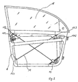
- Die Erfindung sei nun an Hand der Figuren 1 und 2 näher erläutert.
- Fig. 1
- zeigt einen erfindungsgemäßen Türrahmen ohne Funktionsteile
- Fig. 2
- zeigt den Türrahmen wie in Fig. 1 jedoch mit Fenster in geschlossenem Zustand und Fensterhebermechanismus
- In Figur 1 ist mit 1 das rechte Seitenteil des Türrahmens, mit den Bezugszeichen 2 der untere Holm, 3 das Seitenaufprallprofil, 4 der obere Holm oder auch Brüstung genannt, mit 5 das Fensterrahmenteil, das bei Türen mit sogenannten rahmenlosen Fenstern fehlen kann, und mit 6 das linke Seitenteil bezeichnet. Die Teile mit den Bezugszeichen 2 bis 5 werden auch in ihrer Gesamtheit als Querteile bezeichnet.
- Das Seitenteil 1 ist mit den Querteilen über die Verbindungsstellen 101, 102, 103 und 104 verbunden, das Seitenteil 6 über die entsprechenden Verbindungsstellen 601 bis 604. Als vorteilhaft hat es sich erwiesen, die Teile an den Verbindungsstellen 101 bis 104, bzw. 601 bis 604 so zu gestalten, dass Querteile und Seitenteile ineinander gesteckt und anschliessend verschweisst werden. Dies vereinfacht die Montage des Türrahmens. Die Teile müssen zum Verschweissen nicht gesondert fixiert werden. Im allgemeinen genügt eine Lehre zum Einstellen der geforderten Türrahmenmasse, in der danach auch der Schweissvorgang stattfinden kann.
- In das Seitenteil 1 sind verschiedene Funktionsteile integriert. Mit Bezugszeichen 9 ist die rechte Fensterführungschiene bezeichnet. Die linke Fensterführungsschiene befindet sich in Seitenteil 6 und ist mit Bezugszeichen 19 bezeichnet. Diese beiden Führungen sind einstückig in das entsprechende Seitenteil integriert. Hierin kann das bewegliche Fenster, Bezugszeichen 18 in Fig. 2, in geschlossenem Zustand gezeigt, zwischen Offenstellung, wobei sich der dem Fensterrahmenteil 5 zugekehrte obere Rand der Fensterscheibe 18 in Höhe der Brüstung 4 oder nur wenig darüber hinausragend befindet (nicht gezeichnet), und geschlossener Stellung, wie sie in Fig 2 gezeigt ist, bewegt werden.
- Mit den Bezugszeichen 8 und 10 sind zwei Türschanierteile des Türrahmens bezeichnet, die einstückig in das Seitenteil 1 integriert sind. Die entsprechenden Gegenstücke, in die die Teile 8 und 10 in dem Fachmann in bekannter Weise bewegbar eingeführt werden, befinden sich in den Türöffnungen der Karosserie des Fahrzeuges (nicht gezeichnet) und komplettieren die Türscharniere.
- Mit Bezugszeichen 11 ist die Halteplatte für die Montage des Aussenspiegels bezeichnet. Dieses Teil 11 ist ebenfalls integraler Bestandteil des Seitenteiles 1.
- Im Seitenteil 6 ist mit Bezugszeichen 12 eine Vertiefung bezeichnet, in die Das Türschloss eingeführt und befestigt werden kann. Bezugszeichen 13 bezeichnet die einstückig in das Seitenteil 6 integrierte Halterung für den Türgriff. Türschloss und Türgriff sind beide nicht näher ausgeführt, da sie nicht Gegenstand dieser Erfindung sind.
- In den unteren Bereichen der Seitenteile 1 und 6 sind mit Bezugszeichen 20 und 21 Aussteifungselemente bezeichnet, die den Türrahmen gegen Einwirkung von Schubkräften versteifen. Auch diese Teile sind einstückig in die Seitenteile integriert.
- In dem Aussteifungselement 20 ist, mit 7 bezeichnet, die Aufnahme für einen Antriebsmotor 14 für die bewegliche Fensterscheibe 18 enthalten. Im Aussteifungselement 21 befindet sich die Aufnahme für eine Umlenkrolle 151 für den Fensterhebermechanismus.
- Der Fensterhebermechanismus ist in Fig. 2 dargestellt. Es handelt sich um einen an sich bekannten Seilfensterheber mit umlaufendem Seil 16 mit den Umlenkrollen 151, 152 und 153. Die Umlenkrollen 152 und 153 sind an Ohren 22 und 23 drehbar befestigt. Diese Ohren 22 und 23 sind wiedrum einstückig in die Seitenteile 1 und 6 integriert. An diesem Seil sind Halterungen 171 und 172 befestigt, in die die Fensterscheibe 18 eingesteckt ist. Mit Hilfe des Antriebes 14 kann das Seil im Uhrzeigersinn bzw, gegen Uhrzeigersinn bewegt werden. Hierdurch wird die Fensterscheibe 18 in den Fensterführungen 9 und 19 zwischen Offenstellung und Geschlossenstellung bewegt Figur 2 gibt die Geschlossenstellung der Fensterscheibe 18 wieder.
- Die Seitenteile 1 und 6 sind aus einer Leichtmetalllegierung als Druckgussformteile hergestellt. Als Leichtmetalllegierung hat sich als geeignet die Legierung Magsimal-59 (AlMg5Si2Mn) der Fa. Aluminium Rheinfelden GmbH erwiesen. Andere Legierungen aus der Leichtmetallgruppe, wie z.B. auf Magnesiumbasis, sind ebenfalls denkbar.
- Die Querteile 2 bis 5 können als Strangpressprofile aus Material, das sich in Bezug auf elektrochemische Verträglichkeit (Korrosion) mit der Legierung der Seitenteile 1 und 6 verträgt, gebildet werden. Bei entsprechender Steifigkeit und Zähigkeit können dies auch Kunststoffe sein.
- Die Konstruktion der Seitenteile 1 und 6 als Druckgussteile erlaubt die hohe Integration von Funktionselementen wie oben beschrieben. Hierdurch wird die geringe Anzahl an einzelnen Bauteilen ermöglicht, was zu den Vorteilen gegenüber der Konstruktion nach dem Stand der Technik führt.
Claims (11)
- Türrahmen für eine Fahrzeugtür, der aus zwei Seitenteilen (1 und 6) und mindestens zwei, die Seitenteile verbindenden Holmen (2, 3, 4, 5) besteht, wobei die Seitenteile (1 und 6) aus Druckgussformteilen bestehen, dadurch gekennzeichnet, daß in die Seitenteile (1 und 6) Aufnahmen für Umlenkrollen (151, 152, 153) und die Aufnahme (7) für einen Fensterheberantrieb (14) integriert sind.
- Türrahmen nach Anspruch 1, dadurch gekennzeichnet, daß in die Seitenteile (2 und 6) die Führungsschienen (9 und 19) für ein bewegliches Fenster (18) integriert sind.
- Türrahmen nach Anspruch 1, dadurch gekennzeichnet, daß in ein Seitenteil (6) die Aufnahme (12) für ein Türschloß integriert ist.
- Türrahmen nach Anspruch 1, dadurch gekennzeichnet, daß in ein Seitenteil (6) die Halterung (13) für den Türgriff integriert ist.
- Türrahmen nach Anspruch 1, dadurch gekennzeichnet, daß in ein Seitenteil (1) Türscharnierteile (8 und 10) integriert sind.
- Türrahmen nach Anspruch 1, dadurch gekennzeichnet, daß in ein Seitenteil (1) die Befestigungsplatte (11) für den Rückspiegel integriert ist.
- Türrahmen nach Anspruch 1, dadurch gekennzeichnet, daß die Seitenteile (1 und 6) als Druckgussformteile aus einer Leichtmetalllegierung bestehen.
- Türrahmen nach Anspruch 7, dadurch gekennzeichnet, daß es sich bei der Leichtmetalllegierung um eine Aluminiumlegierung handelt.
- Türrahmen nach Anspruch 7, dadurch gekennzeichnet, daß es sich bei der Leichtmetalllegierung um eine Magnesiumlegierung handelt.
- Türrahmen nach Anspruch 1 dadurch gekennzeichnet, daß die Holme (2, 3, 4 und 5) aus Strangpressprofilen bestehen.
- Türrahmen nach Anspruch 10, dadurch gekennzeichnet, daß die Holme (2, 3, 4 und 5) aus einem Material bestehen, das mit dem Material der Seitenteile (1 bzw. 6) im Hinblick auf elektrochemische Verträglichkeit unbedenklich ist.
Applications Claiming Priority (3)
| Application Number | Priority Date | Filing Date | Title |
|---|---|---|---|
| DE10126250 | 2001-05-29 | ||
| DE10126250A DE10126250A1 (de) | 2001-05-29 | 2001-05-29 | Türrahmen für eine Fahrzeugtür |
| PCT/EP2002/005902 WO2002096690A1 (de) | 2001-05-29 | 2002-05-29 | Türrahmen für eine fahrzeugtür |
Publications (2)
| Publication Number | Publication Date |
|---|---|
| EP1390222A1 EP1390222A1 (de) | 2004-02-25 |
| EP1390222B1 true EP1390222B1 (de) | 2006-02-08 |
Family
ID=7686592
Family Applications (1)
| Application Number | Title | Priority Date | Filing Date |
|---|---|---|---|
| EP02750986A Expired - Lifetime EP1390222B1 (de) | 2001-05-29 | 2002-05-29 | Türrahmen für eine fahrzeugtür |
Country Status (6)
| Country | Link |
|---|---|
| US (1) | US20040195860A1 (de) |
| EP (1) | EP1390222B1 (de) |
| JP (1) | JP2004526627A (de) |
| AT (1) | ATE317341T1 (de) |
| DE (2) | DE10126250A1 (de) |
| WO (1) | WO2002096690A1 (de) |
Families Citing this family (17)
| Publication number | Priority date | Publication date | Assignee | Title |
|---|---|---|---|---|
| SE518503C2 (sv) * | 2001-02-09 | 2002-10-15 | Ssab Hardtech Ab | Fordonsdörr med bältesbalk och sidokrockskyddsbalk tillverkade i ett stycke med dörramen, samt sätt att tillverka en sådan |
| DE10217831A1 (de) * | 2002-04-16 | 2003-11-06 | Sai Automotive Sal Gmbh | Fahrzeugtür und Verfahren zu deren Herstellung |
| DE10301042B3 (de) * | 2003-01-13 | 2004-08-19 | Drm Druckguss Gmbh | Fensterrahmenteil, hergestellt im Metall-Druckgießverfahren |
| JP4622635B2 (ja) * | 2005-04-01 | 2011-02-02 | トヨタ自動車株式会社 | 車両用ドア構造 |
| DE102005030507B4 (de) * | 2005-06-28 | 2008-04-03 | Benteler Automobiltechnik Gmbh | Türstruktur eines Kraftfahrzeugs |
| EP2013046A1 (de) * | 2006-04-28 | 2009-01-14 | Alcoa Inc. | Leichtgewichtige modulare scharniertür |
| DE102007032651A1 (de) * | 2007-07-13 | 2009-01-15 | Dr. Ing. H.C. F. Porsche Aktiengesellschaft | Kraftfahrzeugtür |
| DE102007032901A1 (de) * | 2007-07-14 | 2009-01-15 | Dr. Ing. H.C. F. Porsche Aktiengesellschaft | Außenrückblickspiegel für Fahrzeuge, insbesondere Personenkraftwagen |
| DE102007061209B4 (de) * | 2007-12-19 | 2017-06-08 | Daimler Ag | Seitentür für einen Kraftwagen |
| DE102008017977A1 (de) * | 2008-04-09 | 2009-10-15 | Daimler Ag | Leichtbauteil für eine Fahrzeugkarosserie |
| US8424207B2 (en) | 2008-10-27 | 2013-04-23 | Honda Motor Co., Ltd. | Method of making a composite component and apparatus |
| US8454078B2 (en) * | 2009-11-17 | 2013-06-04 | GM Global Technology Operations LLC | Automotive vehicle door construction |
| DE102011089066A1 (de) * | 2011-12-19 | 2013-06-20 | Bayerische Motoren Werke Aktiengesellschaft | Seitentür für einen Kraftwagen |
| DE202014104378U1 (de) | 2014-09-15 | 2015-12-16 | Indikar Individual Karosseriebau Gmbh | Rahmen, insbesondere Türrahmen für ein Sicherheitskraftfahrzeug |
| JP6387981B2 (ja) * | 2016-02-19 | 2018-09-12 | マツダ株式会社 | 自動車のドア構造 |
| EP3509882B1 (de) * | 2016-09-09 | 2024-04-24 | Teijin Automotive Technologies, Inc. | Zusammengesetzte fahrzeugtürkomponenten aus sheet-molding-compound-harztransfer-formanordnungen |
| CN109515128B (zh) * | 2018-10-25 | 2020-04-10 | 北京长城华冠汽车科技股份有限公司 | 新能源汽车的车门框架总成及新能源汽车 |
Family Cites Families (22)
| Publication number | Priority date | Publication date | Assignee | Title |
|---|---|---|---|---|
| JPS56163014U (de) * | 1980-05-07 | 1981-12-03 | ||
| JPS63106135A (ja) * | 1986-10-23 | 1988-05-11 | Nissan Motor Co Ltd | 自動車用ドア |
| JPH0726507B2 (ja) * | 1988-07-15 | 1995-03-22 | 株式会社大井製作所 | 窓ガラス昇降装置及びそれを自動車のドアに組付ける方法 |
| DE4008111A1 (de) * | 1990-03-14 | 1991-09-19 | Audi Ag | Fahrzeugtuere |
| DE4306290A1 (de) * | 1993-03-01 | 1994-09-08 | Ymos Ag Ind Produkte | Fahrzeugtür |
| JPH06320955A (ja) * | 1993-05-11 | 1994-11-22 | Mazda Motor Corp | 車両のドア構造 |
| JP3508174B2 (ja) * | 1993-09-10 | 2004-03-22 | マツダ株式会社 | 自動車のドア構造 |
| JPH07117727A (ja) * | 1993-10-22 | 1995-05-09 | Mazda Motor Corp | 自動車の車体構造 |
| JP3382729B2 (ja) * | 1994-08-25 | 2003-03-04 | 国立環境研究所長 | 自動車のドア構造 |
| JP3351947B2 (ja) * | 1995-01-19 | 2002-12-03 | 日本軽金属株式会社 | ダイカスト製ドアパネル及びその製造方法 |
| FR2741844B1 (fr) * | 1995-12-01 | 1998-01-09 | Creica | Element metallique de structure d'un ouvrant de carrosserie de vehicule automobile, et ouvrant comportant un tel element de structure |
| JPH1037592A (ja) * | 1996-07-19 | 1998-02-10 | Asmo Co Ltd | パワーウインド装置 |
| GB9617549D0 (en) * | 1996-08-21 | 1996-10-02 | Rover Group | Vehicle door structures |
| JP3228147B2 (ja) * | 1996-09-25 | 2001-11-12 | 三菱自動車工業株式会社 | ドア構造 |
| JPH10119574A (ja) * | 1996-10-16 | 1998-05-12 | Mitsubishi Motors Corp | ドア装置 |
| US5809695A (en) * | 1997-01-27 | 1998-09-22 | Hi-Lex Corporation | Window regulator |
| DE19713317B4 (de) * | 1997-03-29 | 2004-12-16 | Wagon Automotive Gmbh | Heckklappe |
| DE19727010B4 (de) * | 1997-06-25 | 2006-03-09 | Wagon Automotive Gmbh | Fensterrahmenmodul zur Herstellung von Kraftfahrzeugtüren |
| EP0916534B1 (de) * | 1997-11-13 | 2006-02-15 | Schade GmbH & Co. KG | Rohbautür eines Fahrzeugs |
| JP3558532B2 (ja) * | 1998-08-31 | 2004-08-25 | アイシン精機株式会社 | 車両用ドア |
| DE19920841B4 (de) * | 1999-05-06 | 2010-07-08 | Volkswagen Ag | Fahrzeugtür |
| JP2000351380A (ja) * | 1999-06-09 | 2000-12-19 | Koyo Seiko Co Ltd | ステアリング装置のハウジング構造 |
-
2001
- 2001-05-29 DE DE10126250A patent/DE10126250A1/de not_active Ceased
-
2002
- 2002-05-29 WO PCT/EP2002/005902 patent/WO2002096690A1/de not_active Ceased
- 2002-05-29 EP EP02750986A patent/EP1390222B1/de not_active Expired - Lifetime
- 2002-05-29 DE DE50205797T patent/DE50205797D1/de not_active Expired - Lifetime
- 2002-05-29 JP JP2002593182A patent/JP2004526627A/ja active Pending
- 2002-05-29 US US10/478,600 patent/US20040195860A1/en not_active Abandoned
- 2002-05-29 AT AT02750986T patent/ATE317341T1/de not_active IP Right Cessation
Also Published As
| Publication number | Publication date |
|---|---|
| DE50205797D1 (de) | 2006-04-20 |
| JP2004526627A (ja) | 2004-09-02 |
| EP1390222A1 (de) | 2004-02-25 |
| ATE317341T1 (de) | 2006-02-15 |
| WO2002096690A1 (de) | 2002-12-05 |
| DE10126250A1 (de) | 2002-12-12 |
| US20040195860A1 (en) | 2004-10-07 |
Similar Documents
| Publication | Publication Date | Title |
|---|---|---|
| DE68913838T2 (de) | Fensterheber einer Kraftfahrzeugtür und Verfahren zum Anbringen dieses Hebers an einer Kraftfahrzeugtür. | |
| EP0937853B1 (de) | Betätigungseinrichtung für eine Schiebetür, insbesondere für Kraftfahrzeuge | |
| DE60310628T2 (de) | Doppeltür-Anordnung für Fahrzeuge | |
| EP2265485B1 (de) | Leichtbauteil für eine fahrzeugkarosserie | |
| EP1390222A1 (de) | Türrahmen für eine fahrzeugtür | |
| DE10063459A1 (de) | Leichtbautür für Kraftfahrzeuge | |
| DE102007032651A1 (de) | Kraftfahrzeugtür | |
| DE3119595A1 (de) | Tuersystem fuer den seitlichen abschluss des fahrgastraums eines motorfahrzeugs | |
| DE60014745T2 (de) | Konstruktion eines öffnungsfähiges Fahrzeugdaches | |
| EP0601286A1 (de) | Tür für ein Kraftfahrzeug | |
| EP1494882B1 (de) | Fahrzeugtür und verfahren zu deren herstellung | |
| DE19519509A1 (de) | Fahrzeugtür mit Rahmenmodul und Seitenaufprallschutz | |
| DE19727010B4 (de) | Fensterrahmenmodul zur Herstellung von Kraftfahrzeugtüren | |
| EP0992383B1 (de) | Türsystem für Nutzfahrzeuge | |
| EP1569812A1 (de) | Kraftfahrzeugtür | |
| DE19944347B4 (de) | Kraftfahrzeugtür | |
| DE3402135A1 (de) | Fahrzeugtuere | |
| DE3823087A1 (de) | Fuehrungsvorrichtung fuer die fensterscheiben innerhalb des aufbaus einer automobiltuer | |
| DE102007061209A1 (de) | Seitentür für einen Kraftwagen | |
| DE19732700B4 (de) | Rahmenanordnung für ein Deckelteil eines Fahrzeugdaches | |
| EP0630775B1 (de) | Fahrzeugtür | |
| DE4331616B4 (de) | Kraftfahrzeugtür | |
| DE19821077A1 (de) | Fahrzeugtür | |
| EP0292960B1 (de) | Kraftfahrzeugtür, insbesondere für Personenkraftwagen | |
| EP0702124A1 (de) | Fingerschutzeinrichtung für ein Sektionaltor |
Legal Events
| Date | Code | Title | Description |
|---|---|---|---|
| PUAI | Public reference made under article 153(3) epc to a published international application that has entered the european phase |
Free format text: ORIGINAL CODE: 0009012 |
|
| 17P | Request for examination filed |
Effective date: 20031106 |
|
| AK | Designated contracting states |
Kind code of ref document: A1 Designated state(s): AT BE CH CY DE DK ES FI FR GB GR IE IT LI LU MC NL PT SE TR |
|
| AX | Request for extension of the european patent |
Extension state: AL LT LV MK RO SI |
|
| GRAP | Despatch of communication of intention to grant a patent |
Free format text: ORIGINAL CODE: EPIDOSNIGR1 |
|
| GRAS | Grant fee paid |
Free format text: ORIGINAL CODE: EPIDOSNIGR3 |
|
| GRAA | (expected) grant |
Free format text: ORIGINAL CODE: 0009210 |
|
| RAP1 | Party data changed (applicant data changed or rights of an application transferred) |
Owner name: FAURECIA INNENRAUM SYSTEME GMBH |
|
| AK | Designated contracting states |
Kind code of ref document: B1 Designated state(s): AT BE CH CY DE DK ES FI FR GB GR IE IT LI LU MC NL PT SE TR |
|
| PG25 | Lapsed in a contracting state [announced via postgrant information from national office to epo] |
Ref country code: IT Free format text: LAPSE BECAUSE OF FAILURE TO SUBMIT A TRANSLATION OF THE DESCRIPTION OR TO PAY THE FEE WITHIN THE PRESCRIBED TIME-LIMIT;WARNING: LAPSES OF ITALIAN PATENTS WITH EFFECTIVE DATE BEFORE 2007 MAY HAVE OCCURRED AT ANY TIME BEFORE 2007. THE CORRECT EFFECTIVE DATE MAY BE DIFFERENT FROM THE ONE RECORDED. Effective date: 20060208 Ref country code: FI Free format text: LAPSE BECAUSE OF FAILURE TO SUBMIT A TRANSLATION OF THE DESCRIPTION OR TO PAY THE FEE WITHIN THE PRESCRIBED TIME-LIMIT Effective date: 20060208 Ref country code: NL Free format text: LAPSE BECAUSE OF FAILURE TO SUBMIT A TRANSLATION OF THE DESCRIPTION OR TO PAY THE FEE WITHIN THE PRESCRIBED TIME-LIMIT Effective date: 20060208 Ref country code: IE Free format text: LAPSE BECAUSE OF FAILURE TO SUBMIT A TRANSLATION OF THE DESCRIPTION OR TO PAY THE FEE WITHIN THE PRESCRIBED TIME-LIMIT Effective date: 20060208 Ref country code: GB Free format text: LAPSE BECAUSE OF FAILURE TO SUBMIT A TRANSLATION OF THE DESCRIPTION OR TO PAY THE FEE WITHIN THE PRESCRIBED TIME-LIMIT Effective date: 20060208 |
|
| REG | Reference to a national code |
Ref country code: GB Ref legal event code: FG4D Free format text: NOT ENGLISH |
|
| REG | Reference to a national code |
Ref country code: CH Ref legal event code: EP |
|
| REG | Reference to a national code |
Ref country code: IE Ref legal event code: FG4D Free format text: LANGUAGE OF EP DOCUMENT: GERMAN |
|
| REF | Corresponds to: |
Ref document number: 50205797 Country of ref document: DE Date of ref document: 20060420 Kind code of ref document: P |
|
| PG25 | Lapsed in a contracting state [announced via postgrant information from national office to epo] |
Ref country code: SE Free format text: LAPSE BECAUSE OF FAILURE TO SUBMIT A TRANSLATION OF THE DESCRIPTION OR TO PAY THE FEE WITHIN THE PRESCRIBED TIME-LIMIT Effective date: 20060508 Ref country code: DK Free format text: LAPSE BECAUSE OF FAILURE TO SUBMIT A TRANSLATION OF THE DESCRIPTION OR TO PAY THE FEE WITHIN THE PRESCRIBED TIME-LIMIT Effective date: 20060508 |
|
| PG25 | Lapsed in a contracting state [announced via postgrant information from national office to epo] |
Ref country code: ES Free format text: LAPSE BECAUSE OF FAILURE TO SUBMIT A TRANSLATION OF THE DESCRIPTION OR TO PAY THE FEE WITHIN THE PRESCRIBED TIME-LIMIT Effective date: 20060519 |
|
| PG25 | Lapsed in a contracting state [announced via postgrant information from national office to epo] |
Ref country code: AT Free format text: LAPSE BECAUSE OF NON-PAYMENT OF DUE FEES Effective date: 20060529 |
|
| PG25 | Lapsed in a contracting state [announced via postgrant information from national office to epo] |
Ref country code: LI Free format text: LAPSE BECAUSE OF NON-PAYMENT OF DUE FEES Effective date: 20060531 Ref country code: BE Free format text: LAPSE BECAUSE OF NON-PAYMENT OF DUE FEES Effective date: 20060531 Ref country code: CH Free format text: LAPSE BECAUSE OF NON-PAYMENT OF DUE FEES Effective date: 20060531 Ref country code: MC Free format text: LAPSE BECAUSE OF NON-PAYMENT OF DUE FEES Effective date: 20060531 |
|
| NLV1 | Nl: lapsed or annulled due to failure to fulfill the requirements of art. 29p and 29m of the patents act | ||
| PG25 | Lapsed in a contracting state [announced via postgrant information from national office to epo] |
Ref country code: PT Free format text: LAPSE BECAUSE OF FAILURE TO SUBMIT A TRANSLATION OF THE DESCRIPTION OR TO PAY THE FEE WITHIN THE PRESCRIBED TIME-LIMIT Effective date: 20060710 |
|
| GBV | Gb: ep patent (uk) treated as always having been void in accordance with gb section 77(7)/1977 [no translation filed] |
Effective date: 20060208 |
|
| REG | Reference to a national code |
Ref country code: IE Ref legal event code: FD4D |
|
| PLBE | No opposition filed within time limit |
Free format text: ORIGINAL CODE: 0009261 |
|
| STAA | Information on the status of an ep patent application or granted ep patent |
Free format text: STATUS: NO OPPOSITION FILED WITHIN TIME LIMIT |
|
| REG | Reference to a national code |
Ref country code: CH Ref legal event code: PL |
|
| 26N | No opposition filed |
Effective date: 20061109 |
|
| EN | Fr: translation not filed | ||
| BERE | Be: lapsed |
Owner name: FAURECIA INNENRAUM SYSTEME G.M.B.H. Effective date: 20060531 |
|
| PG25 | Lapsed in a contracting state [announced via postgrant information from national office to epo] |
Ref country code: FR Free format text: LAPSE BECAUSE OF FAILURE TO SUBMIT A TRANSLATION OF THE DESCRIPTION OR TO PAY THE FEE WITHIN THE PRESCRIBED TIME-LIMIT Effective date: 20070330 Ref country code: GR Free format text: LAPSE BECAUSE OF FAILURE TO SUBMIT A TRANSLATION OF THE DESCRIPTION OR TO PAY THE FEE WITHIN THE PRESCRIBED TIME-LIMIT Effective date: 20060509 |
|
| PG25 | Lapsed in a contracting state [announced via postgrant information from national office to epo] |
Ref country code: TR Free format text: LAPSE BECAUSE OF FAILURE TO SUBMIT A TRANSLATION OF THE DESCRIPTION OR TO PAY THE FEE WITHIN THE PRESCRIBED TIME-LIMIT Effective date: 20060208 Ref country code: LU Free format text: LAPSE BECAUSE OF NON-PAYMENT OF DUE FEES Effective date: 20060529 |
|
| PG25 | Lapsed in a contracting state [announced via postgrant information from national office to epo] |
Ref country code: FR Free format text: LAPSE BECAUSE OF FAILURE TO SUBMIT A TRANSLATION OF THE DESCRIPTION OR TO PAY THE FEE WITHIN THE PRESCRIBED TIME-LIMIT Effective date: 20060531 |
|
| PG25 | Lapsed in a contracting state [announced via postgrant information from national office to epo] |
Ref country code: FR Free format text: LAPSE BECAUSE OF FAILURE TO SUBMIT A TRANSLATION OF THE DESCRIPTION OR TO PAY THE FEE WITHIN THE PRESCRIBED TIME-LIMIT Effective date: 20060208 Ref country code: CY Free format text: LAPSE BECAUSE OF FAILURE TO SUBMIT A TRANSLATION OF THE DESCRIPTION OR TO PAY THE FEE WITHIN THE PRESCRIBED TIME-LIMIT Effective date: 20060208 |
|
| PGFP | Annual fee paid to national office [announced via postgrant information from national office to epo] |
Ref country code: DE Payment date: 20160421 Year of fee payment: 15 |
|
| REG | Reference to a national code |
Ref country code: DE Ref legal event code: R119 Ref document number: 50205797 Country of ref document: DE |
|
| PG25 | Lapsed in a contracting state [announced via postgrant information from national office to epo] |
Ref country code: DE Free format text: LAPSE BECAUSE OF NON-PAYMENT OF DUE FEES Effective date: 20171201 |