EP1388839A2 - Méthode et dispositif d'affichage d'une image - Google Patents
Méthode et dispositif d'affichage d'une image Download PDFInfo
- Publication number
- EP1388839A2 EP1388839A2 EP03254580A EP03254580A EP1388839A2 EP 1388839 A2 EP1388839 A2 EP 1388839A2 EP 03254580 A EP03254580 A EP 03254580A EP 03254580 A EP03254580 A EP 03254580A EP 1388839 A2 EP1388839 A2 EP 1388839A2
- Authority
- EP
- European Patent Office
- Prior art keywords
- image
- frame
- sub
- display
- pixels
- Prior art date
- Legal status (The legal status is an assumption and is not a legal conclusion. Google has not performed a legal analysis and makes no representation as to the accuracy of the status listed.)
- Withdrawn
Links
Images


Classifications
-
- H—ELECTRICITY
- H04—ELECTRIC COMMUNICATION TECHNIQUE
- H04N—PICTORIAL COMMUNICATION, e.g. TELEVISION
- H04N1/00—Scanning, transmission or reproduction of documents or the like, e.g. facsimile transmission; Details thereof
- H04N1/387—Composing, repositioning or otherwise geometrically modifying originals
-
- G—PHYSICS
- G09—EDUCATION; CRYPTOGRAPHY; DISPLAY; ADVERTISING; SEALS
- G09G—ARRANGEMENTS OR CIRCUITS FOR CONTROL OF INDICATING DEVICES USING STATIC MEANS TO PRESENT VARIABLE INFORMATION
- G09G3/00—Control arrangements or circuits, of interest only in connection with visual indicators other than cathode-ray tubes
- G09G3/001—Control arrangements or circuits, of interest only in connection with visual indicators other than cathode-ray tubes using specific devices not provided for in groups G09G3/02 - G09G3/36, e.g. using an intermediate record carrier such as a film slide; Projection systems; Display of non-alphanumerical information, solely or in combination with alphanumerical information, e.g. digital display on projected diapositive as background
- G09G3/002—Control arrangements or circuits, of interest only in connection with visual indicators other than cathode-ray tubes using specific devices not provided for in groups G09G3/02 - G09G3/36, e.g. using an intermediate record carrier such as a film slide; Projection systems; Display of non-alphanumerical information, solely or in combination with alphanumerical information, e.g. digital display on projected diapositive as background to project the image of a two-dimensional display, such as an array of light emitting or modulating elements or a CRT
-
- G—PHYSICS
- G09—EDUCATION; CRYPTOGRAPHY; DISPLAY; ADVERTISING; SEALS
- G09G—ARRANGEMENTS OR CIRCUITS FOR CONTROL OF INDICATING DEVICES USING STATIC MEANS TO PRESENT VARIABLE INFORMATION
- G09G3/00—Control arrangements or circuits, of interest only in connection with visual indicators other than cathode-ray tubes
- G09G3/007—Use of pixel shift techniques, e.g. by mechanical shift of the physical pixels or by optical shift of the perceived pixels
-
- G—PHYSICS
- G09—EDUCATION; CRYPTOGRAPHY; DISPLAY; ADVERTISING; SEALS
- G09G—ARRANGEMENTS OR CIRCUITS FOR CONTROL OF INDICATING DEVICES USING STATIC MEANS TO PRESENT VARIABLE INFORMATION
- G09G2330/00—Aspects of power supply; Aspects of display protection and defect management
- G09G2330/08—Fault-tolerant or redundant circuits, or circuits in which repair of defects is prepared
-
- G—PHYSICS
- G09—EDUCATION; CRYPTOGRAPHY; DISPLAY; ADVERTISING; SEALS
- G09G—ARRANGEMENTS OR CIRCUITS FOR CONTROL OF INDICATING DEVICES USING STATIC MEANS TO PRESENT VARIABLE INFORMATION
- G09G2330/00—Aspects of power supply; Aspects of display protection and defect management
- G09G2330/10—Dealing with defective pixels
-
- G—PHYSICS
- G09—EDUCATION; CRYPTOGRAPHY; DISPLAY; ADVERTISING; SEALS
- G09G—ARRANGEMENTS OR CIRCUITS FOR CONTROL OF INDICATING DEVICES USING STATIC MEANS TO PRESENT VARIABLE INFORMATION
- G09G2340/00—Aspects of display data processing
- G09G2340/04—Changes in size, position or resolution of an image
- G09G2340/0407—Resolution change, inclusive of the use of different resolutions for different screen areas
- G09G2340/0414—Vertical resolution change
-
- G—PHYSICS
- G09—EDUCATION; CRYPTOGRAPHY; DISPLAY; ADVERTISING; SEALS
- G09G—ARRANGEMENTS OR CIRCUITS FOR CONTROL OF INDICATING DEVICES USING STATIC MEANS TO PRESENT VARIABLE INFORMATION
- G09G2340/00—Aspects of display data processing
- G09G2340/04—Changes in size, position or resolution of an image
- G09G2340/0407—Resolution change, inclusive of the use of different resolutions for different screen areas
- G09G2340/0421—Horizontal resolution change
-
- G—PHYSICS
- G09—EDUCATION; CRYPTOGRAPHY; DISPLAY; ADVERTISING; SEALS
- G09G—ARRANGEMENTS OR CIRCUITS FOR CONTROL OF INDICATING DEVICES USING STATIC MEANS TO PRESENT VARIABLE INFORMATION
- G09G2340/00—Aspects of display data processing
- G09G2340/04—Changes in size, position or resolution of an image
- G09G2340/0407—Resolution change, inclusive of the use of different resolutions for different screen areas
- G09G2340/0435—Change or adaptation of the frame rate of the video stream
-
- G—PHYSICS
- G09—EDUCATION; CRYPTOGRAPHY; DISPLAY; ADVERTISING; SEALS
- G09G—ARRANGEMENTS OR CIRCUITS FOR CONTROL OF INDICATING DEVICES USING STATIC MEANS TO PRESENT VARIABLE INFORMATION
- G09G3/00—Control arrangements or circuits, of interest only in connection with visual indicators other than cathode-ray tubes
- G09G3/20—Control arrangements or circuits, of interest only in connection with visual indicators other than cathode-ray tubes for presentation of an assembly of a number of characters, e.g. a page, by composing the assembly by combination of individual elements arranged in a matrix no fixed position being assigned to or needed to be assigned to the individual characters or partial characters
Definitions
- the present invention relates generally to imaging systems, and more particularly to a system and method of displaying an image.
- a conventional system or device for displaying an image such as a display, projector, or other imaging system, produces a displayed image by addressing an array of individual picture elements or pixels arranged in horizontal rows and vertical columns.
- the displayed image will replicate the defect. For example, if a pixel of the display device exhibits only an "ON" position, the pixel may produce a solid white square in the displayed image. In addition, if a pixel of the display device exhibits only an "OFF" position, the pixel may produce a solid black square in the displayed image.
- the affect of the defective pixel or pixels of the display device may be readily visible in the displayed image.
- One aspect of the present invention provides a method of displaying an image with a display device including a plurality of display pixels.
- the method includes receiving image data for the image, the image data including individual pixels of the image; buffering the image data and creating a frame of the image, the frame of the image including a plurality of columns and a plurality of rows of the pixels of the image; defining a first sub-frame and at least a second sub-frame for the frame of the image, image data of the second sub-frame being offset from image data of the first sub-frame by an offset distance of at least one pixel; and displaying the first sub-frame with a first plurality of the display pixels and displaying the second sub-frame with a second plurality of the display pixels offset from the first plurality of the display pixels by the offset distance.
- Figure 1 is a block diagram illustrating one embodiment of an image display system.
- Figures 2A-2C are schematic illustrations of one embodiment of processing and displaying a frame of an image according to the present invention.
- Figures 3A-3C are schematic illustrations of one embodiment of displaying a pixel with an image display system according to the present invention.
- Figure 4 is a simulation of one embodiment of an enlarged image portion produced without processing by an image display system according to the present invention.
- Figure 5 is a simulation of one embodiment of an enlarged image portion produced with processing by an image display system according to the present invention.
- Figures 6A-6E are schematic illustrations of another embodiment of processing and displaying a frame of an image according to the present invention.
- Figures 7A-7E are schematic illustrations of one embodiment of displaying a pixel with an image display system according to the present invention.
- Figure 8 is a simulation of another embodiment of an enlarged image portion produced without processing by an image display system according to the present invention.
- Figure 9 is a simulation of another embodiment of an enlarged image portion produced with processing by an image display system according to the present invention.
- Figure 10 is a schematic illustration of one embodiment of display pixels of a display device according to the present invention.
- Figure 11 is a schematic illustration of one embodiment of image data for an image frame according to the present invention.
- Figures 12A-12D are schematic illustrations of one embodiment of image sub-frames for the image frame of Figure 11.
- Figures 13A-13D are schematic illustrations of one embodiment of displayed image portions for the image frame of Figure 11 produced with the image sub-frames of Figures 12A-12D.
- Figures 14A-14D are schematic illustrations of one embodiment of display of the displayed image portions of Figures 13A-13D.
- Figure 14E is a schematic illustration of one embodiment of shifting the displayed image portions of Figures 14A-14D.
- Figure 15 is a schematic illustration of one embodiment of display of the image data for the image frame of Figure 11 with an image display system according to the present invention.
- Figure 16 is a schematic illustration of another embodiment of shifting displayed image portions for a displayed image produced with an image display system according to the present invention.
- Figure 17 is a schematic illustration of another embodiment of shifting displayed image portions for a displayed image produced with an image display system according to the present invention.
- Figure 18 is a schematic illustration of another embodiment of shifting displayed image portions for a displayed image produced with an image display system according to the present invention.
- Figure 19 is a schematic illustration of another embodiment of shifting displayed image portions for a displayed image produced with an image display system according to the present invention.
- Figure 20 is a schematic illustration of another embodiment of shifting displayed image portions for a displayed image produced with an image display system according to the present invention.
- Figure 21 is a schematic illustration of another embodiment of shifting displayed image portions for a displayed image produced with an image display system according to the present invention.
- Figure 22 is a simulation of one embodiment of an enlarged image portion produced without processing by an image display system according to the present invention.
- Figure 23 is a simulation of one embodiment of an enlarged image portion produced with processing by an image display system including resolution enhancement and error hiding according to the present invention.
- Figure 1 illustrates one embodiment of an image display system 10.
- Image display system 10 facilitates processing of an image 12 to create a displayed image 14.
- Image 12 is defined to include any pictorial, graphical, and/or textural characters, symbols, illustrations, and/or other representation of information.
- Image 12 is represented, for example, by image data 16.
- Image data 16 includes individual picture elements or pixels of image 12. While one image is illustrated and described as being processed by image display system 10, it is understood that a plurality or series of images may be processed and displayed by image display system 10.
- image display system 10 includes a frame rate conversion unit 20 and an image frame buffer 22, an image processing unit 24, and a display device 26.
- frame rate conversion unit 20 and image frame buffer 22 receive and buffer image data 16 for image 12 to create an image frame 28 for image 12.
- image processing unit 24 processes image frame 28 to define one or more image sub-frames 30 for image frame 28, and display device 26 temporally and spatially displays image sub-frames 30 to produce displayed image 14.
- Image display system 10, including frame rate conversion unit 20 and/or image processing unit 24, includes hardware, software, firmware, or a combination of these.
- one or more components of image display system 10, including frame rate conversion unit 20 and/or image processing unit 24, are included in a computer, computer server, or other microprocessor-based system capable of performing a sequence of logic operations.
- processing can be distributed throughout the system with individual portions being implemented in separate system components.
- Image data 16 may include digital image data 161 or analog image data 162.
- image display system 10 includes an analog-to-digital (A/D) converter 32.
- A/D converter 32 converts analog image data 162 to digital form for subsequent processing.
- image display system 10 may receive and process digital image data 161 and/or analog image data 162 for image 12.
- Frame rate conversion unit 20 receives image data 16 for image 12 and buffers or stores image data 16 in image frame buffer 22. More specifically, frame rate conversion unit 20 receives image data 16 representing individual lines or fields of image 12 and buffers image data 16 in image frame buffer 22 to create image frame 28 for image 12. Image frame buffer 22 buffers image data 16 by receiving and storing all of the image data for image frame 28 and frame rate conversion unit 20 creates image frame 28 by subsequently retrieving or extracting all of the image data for image frame 28 from image frame buffer 22. As such, image frame 28 is defined to include a plurality of individual lines or fields of image data 16 representing an entirety of image 12. Thus, image frame 28 includes a plurality of columns and a plurality of rows of individual pixels representing image 12.
- Frame rate conversion unit 20 and image frame buffer 22 can receive and process image data 16 as progressive image data and/or interlaced image data. With progressive image data, frame rate conversion unit 20 and image frame buffer 22 receive and store sequential fields of image data 16 for image 12. Thus, frame rate conversion unit 20 creates image frame 28 by retrieving the sequential fields of image data 16 for image 12. With interlaced image data, frame rate conversion unit 20 and image frame buffer 22 receive and store odd fields and even fields of image data 16 for image 12. For example, all of the odd fields of image data 16 are received and stored and all of the even fields of image data 16 are received and stored. As such, frame rate conversion unit 20 de-interlaces image data 16 and creates image frame 28 by retrieving the odd and even fields of image data 16 for image 12.
- Image frame buffer 22 includes memory for storing image data 16 for one or more image frames 28 of respective images 12. Thus, image frame buffer 22 constitutes a database of one or more image frames 28. Examples of image frame buffer 22 include non-volatile memory (e.g., a hard disk drive or other persistent storage device) and may include volatile memory (e.g., random access memory (RAM)).
- non-volatile memory e.g., a hard disk drive or other persistent storage device
- volatile memory e.g., random access memory (RAM)
- image data 16 at frame rate conversion unit 20 By receiving image data 16 at frame rate conversion unit 20 and buffering image data 16 with image frame buffer 22, input timing of image data 16 can be decoupled from a timing requirement of display device 26. More specifically, since image data 16 for image frame 28 is received and stored by image frame buffer 22, image data 16 can be received as input at any rate. As such, the frame rate of image frame 28 can be converted to the timing requirement of display device 26. Thus, image data 16 for image frame 28 can be extracted from image frame buffer 22 at a frame rate of display device 26.
- image processing unit 24 includes a resolution adjustment unit 34 and a sub-frame generation unit 36.
- resolution adjustment unit 34 receives image data 16 for image frame 28 and adjusts a resolution of image data 16 for display on display device 26, and sub-frame generation unit 36 generates a plurality of image sub-frames 30 for image frame 28.
- image processing unit 24 receives image data 16 for image frame 28 at an original resolution and processes image data 16 to match the resolution of display device 26. For example, image processing unit 24 increases, decreases, and/or leaves unaltered the resolution of image data 16 so as to match the resolution of display device 26.
- display device 26 can display image data 16. Accordingly, with image processing unit 24, image display system 10 can receive and display image data 16 of varying resolutions.
- image processing unit 24 increases a resolution of image data 16.
- image data 16 may be of a resolution less than that of display device 26. More specifically, image data 16 may include lower resolution data, such as 400 pixels by 300 pixels, and display device 26 may support higher resolution data, such as 800 pixels by 600 pixels. As such, image processing unit 24 processes image data 16 to increase the resolution of image data 16 to the resolution of display device 26. Image processing unit 24 may increase the resolution of image data 16 by, for example, pixel replication, interpolation, and/or any other resolution synthesis or generation technique.
- image processing unit 24 decreases a resolution of image data 16.
- image data 16 may be of a resolution greater than that of display device 26. More specifically, image data 16 may include higher resolution data, such as 1600 pixels by 1200 pixels, and display device 26 may support lower resolution data, such as 800 pixels by 600 pixels. As such, image processing unit 24 processes image data 16 to decrease the resolution of image data 16 to the resolution of display device 26. Image processing unit 24 may decrease the resolution of image data 16 by, for example, sub-sampling, interpolation, and/or any other resolution reduction technique.
- Sub-frame generation unit 36 receives and processes image data 16 for image frame 28 to define a plurality of image sub-frames 30 for image frame 28. If resolution adjustment unit 34 has adjusted the resolution of image data 16, sub-frame generation unit 36 receives image data 16 at the adjusted resolution. The adjusted resolution of image data 16 may be increased, decreased, or the same as the original resolution of image data 16 for image frame 28. Sub-frame generation unit 36 generates image sub-frames 30 with a resolution which matches the resolution of display device 26. Image sub-frames 30 are each of an area equal to image frame 28 and each include a plurality of columns and a plurality of rows of individual pixels representing a subset of image data 16 of image 12 and have a resolution which matches the resolution of display device 26.
- Each image sub-frame 30 includes a matrix or array of pixels for image frame 28.
- Image sub-frames 30 are spatially offset from each other such that each image sub-frame 30 includes different pixels and/or portions of pixels. As such, image sub-frames 30 are offset from each other by a vertical distance and/or a horizontal distance, as described below.
- Display device 26 receives image sub-frames 30 from image processing unit 24 and sequentially displays image sub-frames 30 to create displayed image 14. More specifically, as image sub-frames 30 are spatially offset from each other, display device 26 displays image sub-frames 30 in different positions according to the spatial offset of image sub-frames 30, as described below. As such, display device 26 alternates between displaying image sub-frames 30 for image frame 28 to create displayed image 14. Accordingly, display device 26 displays an entire sub-frame 30 for image frame 28 at one time.
- display device 26 completes one cycle of displaying image sub-frames 30 for image frame 28.
- display device 26 displays image sub-frames 30 so as to be spatially and temporally offset from each other.
- display device 26 optically steers image sub-frames 30 to create displayed image 14. As such, individual pixels of display device 26 are addressed to multiple locations.
- display device 26 includes an image shifter 38.
- Image shifter 38 spatially alters or offsets the position of image sub-frames 30 as displayed by display device 26. More specifically, image shifter 38 varies the position of display of image sub-frames 30, as described below, to produce displayed image 14.
- display device 26 includes a light modulator for modulation of incident light.
- the light modulator includes, for example, a plurality of micro-mirror devices arranged to form an array of micro-mirror devices. As such, each micro-mirror device constitutes one cell or pixel of display device 26.
- Display device 26 may form part of a display, projector, or other imaging system.
- image display system 10 includes a timing generator 40.
- Timing generator 40 communicates, for example, with frame rate conversion unit 20, image processing unit 24, including resolution adjustment unit 34 and sub-frame generation unit 36, and display device 26, including image shifter 38.
- timing generator 40 synchronizes buffering and conversion of image data 16 to create image frame 28, processing of image frame 28 to adjust the resolution of image data 16 to the resolution of display device 26 and generate image sub-frames 30, and display and positioning of image sub-frames 30 to produce displayed image 14.
- timing generator 40 controls timing of image display system 10 such that entire sub-frames of image 12 are temporally and spatially displayed by display device 26 as displayed image 14.
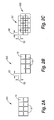
- image processing unit 24 defines a plurality of image sub-frames 30 for image frame 28. More specifically, image processing unit 24 defines a first sub-frame 301 and a second sub-frame 302 for image frame 28. As such, first sub-frame 301 and second sub-frame 302 each include a plurality of columns and a plurality of rows of individual pixels 18 of image data 16. Thus, first sub-frame 301 and second sub-frame 302 each constitute an image data array or pixel matrix of a subset of image data 16.
- second sub-frame 302 is offset from first sub-frame 301 by a vertical distance 50 and a horizontal distance 52. As such, second sub-frame 302 is spatially offset from first sub-frame 301 by a predetermined distance. In one illustrative embodiment, vertical distance 50 and horizontal distance 52 are each approximately one-half of one pixel.
- display device 26 alternates between displaying first sub-frame 301 in a first position and displaying second sub-frame 302 in a second position spatially offset from the first position. More specifically, display device 26 shifts display of second sub-frame 302 relative to display of first sub-frame 301 by vertical distance 50 and horizontal distance 52. As such, pixels of first sub-frame 301 overlap pixels of second sub-frame 302. In one embodiment, display device 26 completes one cycle of displaying first sub-frame 301 in the first position and displaying second sub-frame 302 in the second position for image frame 28. Thus, second sub-frame 302 is spatially and temporally displayed relative to first sub-frame 301.
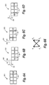
- Figures 3A-3C illustrate one embodiment of completing one cycle of displaying a pixel 181 from first sub-frame 301 in the first position and displaying a pixel 182 from second sub-frame 302 in the second position. More specifically, Figure 3A illustrates display of pixel 181 from first sub-frame 301 in the first position, Figure 3B illustrates display of pixel 182 from second sub-frame 302 in the second position (with the first position being illustrated by dashed lines), and Figure 3C illustrates display of pixel 181 from first sub-frame 301 in the first position (with the second position being illustrated by dashed lines).
- Figures 4 and 5 illustrate enlarged image portions produced from the same image data without and with, respectively, image processing by image display system 10. More specifically, Figure 4 illustrates an enlarged image portion 60 produced without processing by image display system 10. As illustrated in Figure 4, enlarged image portion 60 appears pixelated with individual pixels being readily visible. In addition, enlarged image portion 60 is of a lower resolution.
- Figure 5 illustrates an enlarged image portion 62 produced with processing by image display system 10.
- enlarged image portion 62 does not appear as pixelated as enlarged image portion 60 of Figure 4.
- image quality of enlarged image portion 62 is enhanced with image display system 10. More specifically, resolution of enlarged image portion 62 is improved or increased compared to enlarged image portion 60.
- enlarged image portion 62 is produced by two-position processing including a first sub-frame and a second sub-frame, as described above.
- twice the amount of pixel data is used to create enlarged image portion 62 as compared to the amount of pixel data used to create enlarged image portion 60.
- the resolution of enlarged image portion 62 is increased relative to the resolution of enlarged image portion 60 by a factor of approximately 1.4 or the square root of two.
- image processing unit 24 defines a plurality of image sub-frames 30 for image frame 28. More specifically, image processing unit 24 defines a first sub-frame 301, a second sub-frame 302, a third sub-frame 303, and a fourth sub-frame 304 for image frame 28. As such, first sub-frame 301, second sub-frame 302, third sub-frame 303, and fourth sub-frame 304 each include a plurality of columns and a plurality of rows of individual pixels 18 of image data 16.
- second sub-frame 302 is offset from first sub-frame 301 by a vertical distance 50 and a horizontal distance 52
- third sub-frame 303 is offset from first sub-frame 301 by a horizontal distance 54
- fourth sub-frame 304 is offset from first sub-frame 301 by a vertical distance 56.
- second sub-frame 302, third sub-frame 303, and fourth sub-frame 304 are each spatially offset from each other and spatially offset from first sub-frame 301 by a predetermined distance.
- vertical distance 50, horizontal distance 52, horizontal distance 54, and vertical distance 56 are each approximately one-half of one pixel.
- display device 26 alternates between displaying first sub-frame 301 in a first position P 1 , displaying second sub-frame 302 in a second position P 2 spatially offset from the first position, displaying third sub-frame 303 in a third position P 3 spatially offset from the first position, and displaying fourth sub-frame 304 in a fourth position P 4 spatially offset from the first position. More specifically, display device 26 shifts display of second sub-frame 302, third sub-frame 303, and fourth sub-frame 304 relative to first sub-frame 301 by the respective predetermined distance. As such, pixels of first sub-frame 301, second sub-frame 302, third sub-frame 303, and fourth sub-frame 304 overlap each other.
- display device 26 completes one cycle of displaying first sub-frame 301 in the first position, displaying second sub-frame 302 in the second position, displaying third sub-frame 303 in the third position, and displaying fourth sub-frame 304 in the fourth position for image frame 28.
- second sub-frame 302, third sub-frame 303, and fourth sub-frame 304 are spatially and temporally displayed relative to each other and relative to first sub-frame 301.
- Figures 7A-7E illustrate one embodiment of completing one cycle of displaying a pixel 181 from first sub-frame 301 in the first position, displaying a pixel 182 from second sub-frame 302 in the second position, displaying a pixel 183 from third sub-frame 303 in the third position, and displaying a pixel 184 from fourth sub-frame 304 in the fourth position.
- Figure 7A illustrates display of pixel 181 from first sub-frame 301 in the first position
- Figure 7B illustrates display of pixel 182 from second sub-frame 302 in the second position (with the first position being illustrated by dashed lines)
- Figure 7C illustrates display of pixel 183 from third sub-frame 303 in the third position (with the first position and the second position being illustrated by dashed lines)
- Figure 7D illustrates display of pixel 184 from fourth sub-frame 304 in the fourth position (with the first position, the second position, and the third position being illustrated by dashed lines)
- Figure 7E illustrates display of pixel 181 from first sub-frame 301 in the first position (with the second position, the third position, and the fourth position being illustrated by dashed lines).
- Figures 8 and 9 illustrate enlarged image portions produced from the same image data without and with, respectively, image processing by image display system 10. More specifically, Figure 8 illustrates an enlarged image portion 64 produced without processing by image display system 10. As illustrated in Figure 8, areas of enlarged image portion 64 appear pixelated with individual pixels including, for example, pixels forming and/or outlining letters of enlarged image portion 64 being readily visible.
- Figure 9 illustrates an enlarged image portion 66 produced with processing by image display system 10.
- enlarged image portion 66 does not appear pixelated compared to enlarged image portion 64 of Figure 8.
- image quality of enlarged image portion 66 is enhanced with image display system 10. More specifically, resolution of enlarged image portion 66 is improved or increased compared to enlarged image portion 64.
- enlarged image portion 66 is produced by four-position processing including a first sub-frame, a second sub-frame, a third sub-frame, and a fourth sub-frame, as described above.
- four times the amount of pixel data is used to create enlarged image portion 66 as compared to the amount of pixel data used to create enlarged image portion 64.
- the resolution of enlarged image portion 64 is increased relative to the resolution of enlarged image portion 64 by a factor of two or the square root of four.
- Four-position processing therefore, allows image data 16 to be displayed at double the resolution of display device 26 since double the number of pixels in each axis (x and y) gives four times as many pixels.
- image display system 10 can produce displayed image 14 with a resolution greater than that of display device 26.
- image data 16 having a resolution of 800 pixels by 600 pixels
- display device 26 having a resolution of 800 pixels by 600 pixels
- four-position processing by image display system 10 with resolution adjustment of image data 16 produces displayed image 14 with a resolution of 1600 pixels by 1200 pixels. Accordingly, with lower resolution image data and a lower resolution display device, image display system 10 can produce a higher resolution displayed image.
- image display system 10 can produce a higher resolution displayed image.
- image display system 10 can reduce the "screen-door" effect caused, for example, by gaps between adjacent micro-mirror devices of a light modulator.
- image display system 10 can produce displayed image 14 with improved resolution over the entire image.
- image display system 10 can produce displayed image 14 with an increased resolution greater than that of display device 26.
- higher resolution data can be supplied to image display system 10 as original image data or synthesized by image display system 10 from the original image data.
- lower resolution data can be supplied to image display system 10 and used to produce displayed image 14 with a resolution greater than that of display device 26.
- Use of lower resolution data allows for sending of images at a lower data rate while still allowing for higher resolution display of the data.
- use of a lower data rate may enable lower speed data interfaces and result in potentially less EMI radiation.
- display device 26 includes a plurality of columns and a plurality of rows of display pixels 70.
- Display pixels 70 modulate light to display image sub-frames 30 for image frame 28 and produce displayed image 14.
- Each display pixel 70 may include all three color parts, namely, red, green, and blue. In that case, each display pixel 70 of display device 26 is capable of producing a full gamut of colors for display.
- display device 26 includes a 6x6 array of display pixels 70.
- Display pixels 70 are identified, for example, by row (A-F) and column (1-6). While display device 26 is illustrated as including a 6x6 array of display pixels, it is understood that the actual number of display pixels 70 in display device 26 may vary.
- one or more display pixels 70 of display device 26 may be defective.
- display pixel 70 in location C3 is a defective display pixel 72.
- a defective display pixel is defined to include an aberrant or inoperative display pixel of display device 26 such as a display pixel which exhibits only an "ON" or an "OFF' position, a display pixel which produces less intensity or more intensity than intended, and/or a display pixel with inconsistent or random operation.
- image display system 10 diffuses the affect of a defective display pixel or pixels of display device 26. As described below, image display system 10 diffuses the affect of a defective display pixel or pixels by separating or dispersing areas of displayed image 14 which are produced by a defective display pixel of display device 26.
- Figure 11 illustrates one embodiment of image frame 28 for image 12.
- image data 16 for image 12 is buffered to create image frame 28 such that image frame 28 includes a plurality of columns and a plurality of rows of individual pixels 18 of image data 16.
- image frame 28 includes a 4x4 array of pixels 18. Pixels 18 of image data 16 are identified, for example, by roman numerals I-XVI.
- image processing unit 24 defines a plurality of image sub-frames 30' ( Figure 1) for image frame 28. More specifically, image processing unit 24 defines a first image sub-frame 301', a second image sub-frame 302', a third image sub-frame 303', and a fourth image sub-frame 304' for image frame 28.
- First image sub-frame 301', second image sub-frame 302', third image sub-frame 303', and fourth image sub-frame 304' each include image data 16 for image frame 28 and, in one embodiment, are each of an area equal to that of display device 26.
- a top left of each image sub-frame 30' is indexed or mapped to display pixel A1 of display device 26 ( Figure 10), as described below.
- image data 16 is of an area less than that of display device 26. As such, image data 16 can be shifted among display pixels 70 of display device 26 to diffuse the affect of a defective display pixel, as described below. Thus, display pixels 70 outside of image data 16 are identified as blank display pixels 74 ( Figure 13A).
- image processing unit 24 scales image data 16 so as to be of a size less than that of display device 26.
- display device 26 is of a size greater than a standard size of image data 16.
- display device 26 has a size of 602 pixels by 802 pixels so as to accommodate image data 16 of a standard size of 600 pixels by 800 pixels.
- image data 16 of second image sub-frame 302' is offset from image data 16 of first image sub-frame 301' by horizontal distance 52
- image data 16 of third image sub-frame 303' is offset from image data 16 of second image sub-frame 302' by vertical distance 50
- image data 16 of fourth image sub-frame 304' is offset from image data 16 of third image sub-frame 303' by horizontal distance 54.
- image data 16 of first image sub-frame 301', image data 16 of second image sub-frame 302', image data 16 of third image sub-frame 303', and image data 16 of fourth image sub-frame 304' are spatially offset from each other by a predetermined distance.
- the predetermined distance includes n pixels, wherein n is a whole number.
- horizontal distance 52, vertical distance 50, and horizontal distance 54 are each one pixel.
- display device 26 alternates between displaying first image sub-frame 301', second image sub-frame 302', third image sub-frame 303', and fourth image sub-frame 304' for image frame 28.
- first image sub-frame 301', second image sub-frame 302', third image sub-frame 303', and fourth image sub-frame 304' are each displayed with display device 26 such that the top left of each image sub-frame 30' is mapped to display pixel A1 of display device 26.
- image data 16 being offset in each of second image sub-frame 302', third image sub-frame 303', and fourth image sub-frame 304' relative to first image sub-frame 301'
- different display pixels 70 of display device 26 display image data 16 for first image sub-frame 301', second image sub-frame 302', third image sub-frame 303', and fourth image sub-frame 304'.
- display pixels B2-E5 display image data 16 of first image sub-frame 301' as a displayed image portion 141.
- display pixel 70 in location C3 is a defective display pixel
- pixel VI of image data 16 as displayed for first image sub-frame 301' of image frame 28 is defective.
- display pixels B1-E4 display image data 16 for second image sub-frame 302' as a displayed image portion 142.
- display pixel 70 in location C3 is a defective display pixel
- pixel VII of image data 16 as displayed for second image sub-frame 302' of image frame 28 is defective.
- display pixels A1-D4 display image data 16 for third image sub-frame 303' as a displayed image portion 143.
- display pixel 70 in location C3 is a defective display pixel
- pixel Xl of image data 16 as displayed for third image sub-frame 303' of image frame 28 is defective.
- display pixels A2-D5 display image data 16 for fourth image sub-frame 304' as a displayed image portion 144.
- display pixel 70 in location C3 is a defective display pixel
- pixel X of image data 16 as displayed for fourth image sub-frame 304' of image frame 28 is defective.
- display device 26 displays displayed image portions 141, 142, 143, and 144 in the same display position. More specifically, display device 26 shifts display of displayed image portions 142, 143, and 144 so as to coincide with the display of displayed image portion 141 in display positions ai-div. As such, display device 26 displays all displayed image portions 141, 142, 143, and 144 in display positions ai-div.
- the pixel for display position bii is defective for displayed image portion 141.
- the pixel for display position biii is defective for displayed image portion 142.
- the pixel for display position biii is defective for displayed image portion 142.
- the pixel for display position ciii is defective for displayed image portion 143.
- the pixel for display position cii is defective for displayed image portion 144.
- displayed image portions 141, 142, 143, and 144 produced from image sub-frames 301', 302', 303', and 304', respectively, are shifted according to the offset distance of the respective image sub-frames 30'. More specifically, displayed image portions 142,143, and 144 are each shifted in a direction opposite the direction by which image data 16 of image sub-frames 302', 303', and 304', respectively, are offset relative to each other.
- image data 16 of image sub-frame 302' is shifted to the left (as illustrated in Figure 12B) relative to image data 16 of image sub-frame 301'.
- displayed image portion 142 is shifted to the right from position A to position B.
- image data 16 of image sub-frame 303' is shifted up (as illustrated in Figure 12C) relative to image data 16 of image sub-frame 302'.
- displayed image portion 143 is shifted down from position B to position C.
- image data 16 of image sub-frame 304' is shifted to the right (as illustrated in Figure 12D) relative to image data 16 of image sub-frame 303'.
- displayed image portion 144 is shifted to the left from position C to position D.
- pixels I-XVI of image data 16 for each image sub-frame 30' of image frame 28 of image 12 are displayed in the same display positions, namely, display positions ai-div, as illustrated in Figures 14A-14D.
- image shifter 38 ( Figure 1) of display device 26 shifts display of image sub-frames 30' as described above. More specifically, image shifter 38 shifts display of second image sub-frame 302', third image sub-frame 303', and fourth image sub-frame 304' to the display position of first image sub-frame 301' so as to align displayed image portions 142, 143, and 144 with displayed image portion 141. Thus, image data within image sub-frames 30' is properly aligned.
- displayed image portions 141, 142, 143, and 144 each contribute to displayed image 14.
- pixels I-XVI of image data 16 for each image sub-frame 301', 302', 303', and 304' contribute to display positions ai-div.
- each display position ai-div displays the corresponding pixels of image data 16.
- display position ai displays pixel I of image data 16 for image sub-frames 301', 302', 303', and 304', as represented by I A +I B +I C +I D , where I A represents pixel I of image data 16 for image sub-frame 301', I B represents pixel I of image data 16 for image sub-frame 302', I C represents pixel I of image data 16 for image sub-frame 303', and I D represents pixel I of image data 16 for image sub-frame 304'.
- display pixel 70 in location C3 is a defective display pixel
- pixel Vl of image data 16 for first image sub-frame 301' is defective
- pixel VII of image data 16 for second image sub-frame 302' is defective
- pixel Xl of image data 16 for third image sub-frame 303' is defective
- pixel X of image data 16 for fourth image sub-frame 304' is defective ( Figures 14A-14D).
- display position bii is represented by D A +VI B +VI C +VI D
- display position biii is represented by VII A +D B +VII C +VII D
- display position ciii is represented by XI A +XI B +D C +XI D
- display position cii is represented by X A +X B +X C +D D
- D A , D B , D C , and D D represent defective pixels from first image sub-frame 301', second image sub-frame 302', third image sub-frame 303', and fourth image sub-frame 304', respectively.
- defective display pixel 72 in location C3 of display device 26 contributes to one of four pixels for each pixel of displayed image 14 in display positions bii, biii, ciii, and cii. Accordingly, in one embodiment, the contribution of a defective display pixel to a pixel of the displayed image is distributed or diffused so as to be equal to 1/D, where D is the number of display pixels touched by the defective display pixel.
- pixels of displayed image 14 in each of the display positions ai-div are produced by four independent display pixels 70 of display device 26 (for example, I A +I B +I C +I D ), pixels of displayed image 14 appear as an average of the four independent display pixels.
- brightness or intensity of each pixel of displayed image 14 includes the average brightness or intensity of four independent display pixels.
- image data 16 of second image sub-frame 302' is offset a horizontal distance from image data 16 of first image sub-frame 301'
- image data 16 of third image sub-frame 303' is offset a vertical distance from image data 16 of second image sub-frame 302'
- image data 16 of fourth image sub-frame 304' is offset a horizontal distance from image data 16 of third image sub-frame 303' such that the horizontal distance and the vertical distance are both n pixels.
- image sub-frames 30' are shifted between respective positions A, B, C, and D.
- n is a whole number. In another embodiment, n is greater than one and is a non-integer.
- image data 16 of second image sub-frame 302' is offset a horizontal distance and a vertical distance from image data 16 of first image sub-frame 301'
- image data 16 of third image sub-frame 303' is offset a vertical distance from image data 16 of second image sub-frame 302'
- image data 16 of fourth image sub-frame 304' is offset a horizontal distance and a vertical distance from image data 16 of third image sub-frame 303' such that the horizontal distance and the vertical distance are both n pixels.
- image sub-frames 30' are shifted between respective positions A, B, C, and D.
- n is a whole number. In another embodiment, n is greater than one and is a non-integer.
- image data 16 of second image sub-frame 302' is offset a horizontal distance and a vertical distance from image data 16 of first image sub-frame 301'
- image data 16 of third image sub-frame 303' is offset a vertical distance from image data 16 of second image sub-frame 302'
- image data 16 of fourth image sub-frame 304' is offset a horizontal distance and a vertical distance from image data 16 of third image sub-frame 303' such that the horizontal distances and the vertical distances include n pixels and m pixels, respectively.
- image sub-frames 30' are shifted between respective positions A, B, C, and D.
- n and m are whole numbers and are not equal to each other.
- n and m are each greater than one and are non-integers.
- a first image frame 28 is created for a first image and a second image frame 28' is created for a second image.
- a first set of image sub-frames 30' are defined for first image frame 28 and a second set of image sub-frames 30" are defined for second image frame 28'.
- the first set of image sub-frames 30' and the second set of image sub-frames 30" each include one or more sub-frames for the respective image frame.
- a first set of displayed image portions for first image frame 28 are produced with the first set of image sub-frames 30' and a second set of displayed image portions for second image frame 28' are produced with the second set of image sub-frames 30".
- first image frame 28 and second image frame 28' are created for one image. As such, multiple image frames are created for the image from image data 16.
- the first set of displayed image portions for first image frame 28 are shifted in a first pattern and the second set of displayed image portions for second image frame 28' are shifted in a second pattern.
- the second pattern is offset from the first pattern.
- the second pattern may be the same or different from the first pattern.
- a first set of display pixels are used to display the first set of image sub-frames 30' and a second set of display pixels are used to display the second set of image sub-frames 30".
- image data 16 of second image sub-frame 302' is offset a horizontal distance from image data 16 of first image sub-frame 301' for each set of image sub-frames 30' and 30
- image data 16 of third image sub-frame 303' is offset a vertical distance from image data 16 of second image sub-frame 302' for each set of image sub-frames 30' and 30
- image data 16 of fourth image sub-frame 304' is offset a horizontal distance from image data 16 of third image sub-frame 303' for each set of image sub-frames 30' and 30" such that the horizontal distance and the vertical distance are both n pixels.
- image sub-frames 30' are shifted between respective positions A, B, C, and D, and image sub-frames 30" are shifted between respective positions E, F, G, and H.
- n is a whole number. In another embodiment, n is greater than one and is a non-integer.
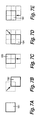
- two image sub-frames 30' are created such that displayed image portions 141 and 142 are shifted in a two-position horizontal pattern.
- image data 16 of second image sub-frame 302' is offset a horizontal distance from image data 16 of first image sub-frame 301', where the horizontal distance includes n pixels.
- image sub-frames 30' are shifted between respective positions A and B.
- n is a whole number. In another embodiment, n is greater than one and is a non-integer.
- two image sub-frames 30' are created such that displayed image portions 141 and 142 are shifted in a two-position vertical pattern.
- image data 16 of second image sub-frame 302' is offset a vertical distance from image data 16 of first image sub-frame 301', where the vertical distance includes n pixels.
- image sub-frames 30' are shifted between respective positions A and B.
- n is a whole number. In another embodiment, n is greater than one and is a non-integer.
- two image sub-frames 30' are created such that displayed image portions 141 and 142 are shifted in a two-position diagonal pattern.
- image data 16 of second image sub-frame 302' is offset a horizontal distance and a vertical distance from image data 16 of first image sub-frame 301', where the horizontal distance and vertical distance include n pixels and m pixels, respectively.
- image sub-frames 30' are shifted between respective positions A and B.
- n and m are whole numbers and are equal to each other.
- n and m are whole numbers and are not equal to each other.
- n and m are each greater than one and are non-integers.
- Figures 22 and 23 illustrate enlarged image portions produced from the same image data without and with, respectively, image processing by image display system 10. More specifically, Figure 22 illustrates an enlarged image portion produced without processing by image display system 10. As illustrated in Figure 22, enlarged image portion 80 appears pixelated with individual pixels being readily visible. In addition, enlarged image portion 80 is of a lower resolution.
- two pixels of enlarged image portion 80 are produced with defective display pixels. More specifically, one pixel 801 of enlarged image portion 80 appears white as the display pixel corresponding to pixel 801 exhibits only an "ON" position. In addition, another pixel 802 of enlarged image portion 80 appears black as the display pixel corresponding to pixel 802 exhibits only an "OFF" position. The affect of these defective display pixels is readily visible in enlarged image portion 80.
- Figure 23 illustrates an enlarged image portion 82 produced with processing by image display system 10 including resolution enhancement and error hiding, as described above. As illustrated in Figure 23, enlarged image portion 82 does not appear pixelated compared to enlarged image portion 80 of Figure 22. Thus, image quality of enlarged image portion 82 is enhanced with image display system 10. More specifically, resolution of enlarged image portion 82 is improved or increased compared to enlarged image portion 80.
- enlarged image portion 82 is produced by four-position processing including a first sub-frame, a second sub-frame, a third sub-frame, and a fourth sub-frame, as described above.
- four times the amount of pixel data is used to create enlarged image portion 82 as compared to the amount of pixel data used to create enlarged image portion 80.
- the resolution of enlarged image portion 82 is increased relative to the resolution of enlarged image portion 80 by a factor of two or the square root of four.
- the affect of the defective display pixels is diffused.
- the affect of the display pixel which exhibits only the "ON" position is distributed or diffused over a region 821 of enlarged image portion 82 including four pixels and the affect of the display pixel which exhibits only the "OFF" position is distributed or diffused over a region 822 of enlarged image portion 82 including four pixels.
- the defective display pixels are not as noticeable in enlarged image portion 82 as compared to enlarged image portion 80.
- the sub-frames used to produce enlarged image portion 82 are offset at least n pixels from each other, wherein n is greater than one and is a non-integer.
- the horizontal distance and/or the vertical distance between the sub-frames includes at least n pixels, wherein n is greater than one and is a non-integer.
- image display system 10 compensates for a defective display pixel or pixels of display device 26. More specifically, a defective display pixel or pixels of display device 26 is identified and image data 16 corresponding to the location of the defective display pixel or pixels in the displayed image is adjusted.
- display position bii includes contribution from a defective display pixel. More specifically, pixel VI of displayed image portion 141 is created with a defective display pixel. Display position bii, however, also includes contributions from three other pixels including pixel VI of displayed image portion 142, pixel VI of displayed image portion 143, and pixel VI of displayed image portion 144. Accordingly, display position bii is represented by D A +VI B +VI C +VI D .
- pixel VI of displayed image portion 141 is produced by the display pixel in location C3.
- image data for other pixels of display position bii is adjusted to compensate for the defective display pixel. More specifically, image data for pixel VI of displayed image portion 142, image data for pixel VI of displayed image portion 143, and/or image data for pixel VI of displayed image portion 144 is adjusted to compensate for pixel VI of displayed image portion 141.
- pixel VI of displayed image portion 142 is produced by the display pixel in location C2
- pixel VI of displayed image portion 143 is produced by the display pixel in location B2
- pixel VI of displayed image portion 144 is produced by the display pixel in location B3.
- pixel VI of displayed image portion 142, pixel VI of displayed image portion 143, nor pixel VI of displayed image portion 144 is affected by the defective display pixel in location C3.
- an intensity of image data 16 corresponding to the location of the defective display pixel or pixels in the displayed image is increased and/or decreased to compensate for the defective display pixel or pixels of display device 26. As such, the affect of the defective display pixel or pixels in the displayed image is reduced.
- the defective display pixel or pixels of display device 26 may be identified by user input, self-diagnostic input or sensing by display device 26, an external data source, and/or information stored in display device 26. In one embodiment, presence of a defective display pixel or pixels of display device 26 is communicated with image processing unit 24, as illustrated in Figure 1.
Landscapes
- Engineering & Computer Science (AREA)
- Physics & Mathematics (AREA)
- Computer Hardware Design (AREA)
- General Physics & Mathematics (AREA)
- Theoretical Computer Science (AREA)
- Multimedia (AREA)
- Signal Processing (AREA)
- Control Of Indicators Other Than Cathode Ray Tubes (AREA)
- Transforming Electric Information Into Light Information (AREA)
- Controls And Circuits For Display Device (AREA)
Applications Claiming Priority (4)
| Application Number | Priority Date | Filing Date | Title |
|---|---|---|---|
| US213555 | 1980-12-05 | ||
| US10/213,555 US7030894B2 (en) | 2002-08-07 | 2002-08-07 | Image display system and method |
| US10/242,195 US7034811B2 (en) | 2002-08-07 | 2002-09-11 | Image display system and method |
| US242195 | 2002-09-11 |
Publications (2)
| Publication Number | Publication Date |
|---|---|
| EP1388839A2 true EP1388839A2 (fr) | 2004-02-11 |
| EP1388839A3 EP1388839A3 (fr) | 2006-09-06 |
Family
ID=30448023
Family Applications (1)
| Application Number | Title | Priority Date | Filing Date |
|---|---|---|---|
| EP03254580A Withdrawn EP1388839A3 (fr) | 2002-08-07 | 2003-07-22 | Méthode et dispositif d'affichage d'une image |
Country Status (5)
| Country | Link |
|---|---|
| US (3) | US7034811B2 (fr) |
| EP (1) | EP1388839A3 (fr) |
| JP (1) | JP4398682B2 (fr) |
| KR (1) | KR100567512B1 (fr) |
| TW (1) | TW594666B (fr) |
Cited By (8)
| Publication number | Priority date | Publication date | Assignee | Title |
|---|---|---|---|---|
| WO2005031692A1 (fr) * | 2003-09-26 | 2005-04-07 | Hewlett-Packard Development Company L.P. | Generation et affichage de sous-trames decalees dans l'espace |
| EP1553548A2 (fr) * | 2003-12-31 | 2005-07-13 | Hewlett-Packard Development Company, L.P. | Procédé et appareil à afficher une image à un affichage avec un ensemble de pixels défectueux |
| WO2005101356A2 (fr) * | 2004-04-08 | 2005-10-27 | Hewlett-Packard Development Company, L.P. | Production et affichage de sous-trames spatialement decalees |
| WO2006034458A2 (fr) * | 2004-09-23 | 2006-03-30 | Hewlett-Packard Development Company, L. P. | Systeme et procede pour la correction de pixels defectueux d'un dispositif d'affichage |
| WO2006058194A2 (fr) * | 2004-11-23 | 2006-06-01 | Hewlett-Packard Development Company L.P. | Systeme et procede pour la correction de pixels defectueux d'un dispositif d'affichage |
| EP1388840A3 (fr) * | 2002-08-07 | 2006-09-27 | Hewlett-Packard Development Company, L.P. | Méthode et dispositif d'affichage d'une image |
| EP1696416A3 (fr) * | 2005-02-24 | 2007-03-21 | NEC Display Solutions Ltd | Dispositif d'affichage et appareil d'affichage grand format l'utilisant |
| WO2019203868A1 (fr) * | 2018-04-16 | 2019-10-24 | Facebook Technologies, Llc | Dispositif d'affichage avec amélioration de résolution dynamique |
Families Citing this family (38)
| Publication number | Priority date | Publication date | Assignee | Title |
|---|---|---|---|---|
| US20030193485A1 (en) * | 2002-04-10 | 2003-10-16 | Da Cunha John M. | Active display system |
| JP4281309B2 (ja) * | 2002-08-23 | 2009-06-17 | ソニー株式会社 | 画像処理装置、画像処理方法、および画像フレームデータ記憶媒体、並びにコンピュータ・プログラム |
| US7683958B1 (en) * | 2003-01-31 | 2010-03-23 | Foveon, Inc. | Camera exposure indication interface |
| US20050093894A1 (en) * | 2003-10-30 | 2005-05-05 | Tretter Daniel R. | Generating an displaying spatially offset sub-frames on different types of grids |
| US7379042B2 (en) * | 2003-11-21 | 2008-05-27 | Au Optronics Corporation | Method for displaying images on electroluminescence devices with stressed pixels |
| US20050225570A1 (en) * | 2004-04-08 | 2005-10-13 | Collins David C | Generating and displaying spatially offset sub-frames |
| US20050225571A1 (en) * | 2004-04-08 | 2005-10-13 | Collins David C | Generating and displaying spatially offset sub-frames |
| WO2005110722A1 (fr) | 2004-05-10 | 2005-11-24 | Envisiontec Gmbh | Procede de production d'un objet en trois dimensions a resolution amelioree par decalage de pixels |
| DE102004022961B4 (de) * | 2004-05-10 | 2008-11-20 | Envisiontec Gmbh | Verfahren zur Herstellung eines dreidimensionalen Objekts mit Auflösungsverbesserung mittels Pixel-Shift |
| US7657118B2 (en) * | 2004-06-09 | 2010-02-02 | Hewlett-Packard Development Company, L.P. | Generating and displaying spatially offset sub-frames using image data converted from a different color space |
| US20050275669A1 (en) * | 2004-06-15 | 2005-12-15 | Collins David C | Generating and displaying spatially offset sub-frames |
| US7668398B2 (en) * | 2004-06-15 | 2010-02-23 | Hewlett-Packard Development Company, L.P. | Generating and displaying spatially offset sub-frames using image data with a portion converted to zero values |
| US20060007198A1 (en) * | 2004-06-29 | 2006-01-12 | Gilbert John D | Apparatus and method for light signal processing utilizing decoupled input and output timing |
| JP2006113229A (ja) * | 2004-10-14 | 2006-04-27 | Seiko Epson Corp | プロジェクタ |
| US7255448B2 (en) * | 2004-10-20 | 2007-08-14 | Hewlett-Packard Development Company, L.P. | Pixelated color management display |
| US7676113B2 (en) * | 2004-11-19 | 2010-03-09 | Hewlett-Packard Development Company, L.P. | Generating and displaying spatially offset sub-frames using a sharpening factor |
| TWI251434B (en) * | 2004-12-08 | 2006-03-11 | Himax Tech Inc | Image processing module with less line buffers |
| US7279812B2 (en) * | 2005-01-18 | 2007-10-09 | Hewlett-Packard Development Company, L.P. | Light direction assembly shorted turn |
| US7586503B2 (en) * | 2005-07-30 | 2009-09-08 | Hewlett-Packard Development Company, L.P. | Reducing acoustical noise in differently aiming sub-frames of image data frame |
| US7545446B2 (en) * | 2005-08-27 | 2009-06-09 | Hewlett-Packard Development Company, L.P. | Offner relay for projection system |
| US20070076171A1 (en) * | 2005-09-20 | 2007-04-05 | Fasen Donald J | Wobulator position sensing system and method |
| US7460133B2 (en) * | 2006-04-04 | 2008-12-02 | Sharp Laboratories Of America, Inc. | Optimal hiding for defective subpixels |
| DE102006019963B4 (de) * | 2006-04-28 | 2023-12-07 | Envisiontec Gmbh | Vorrichtung und Verfahren zur Herstellung eines dreidimensionalen Objekts durch schichtweises Verfestigen eines unter Einwirkung von elektromagnetischer Strahlung verfestigbaren Materials mittels Maskenbelichtung |
| DE102006019964C5 (de) * | 2006-04-28 | 2021-08-26 | Envisiontec Gmbh | Vorrichtung und Verfahren zur Herstellung eines dreidimensionalen Objekts mittels Maskenbelichtung |
| US20080094419A1 (en) | 2006-10-24 | 2008-04-24 | Leigh Stan E | Generating and displaying spatially offset sub-frames |
| US20080143969A1 (en) * | 2006-12-15 | 2008-06-19 | Richard Aufranc | Dynamic superposition system and method for multi-projection display |
| DK2052693T4 (da) | 2007-10-26 | 2021-03-15 | Envisiontec Gmbh | Proces og fri-formfabrikationssystem til at fremstille en tredimensionel genstand |
| KR101346820B1 (ko) | 2012-01-04 | 2014-01-02 | 김철순 | 재활용성 및 친환경성이 우수한 통기성 배수수단을 구비한 식물재배장치 |
| JP2013257476A (ja) * | 2012-06-14 | 2013-12-26 | Sony Corp | 表示装置、画像処理装置、および表示方法 |
| JP6484799B2 (ja) * | 2014-02-04 | 2019-03-20 | パナソニックIpマネジメント株式会社 | 投写型画像表示装置および調整方法 |
| US9527244B2 (en) | 2014-02-10 | 2016-12-27 | Global Filtration Systems | Apparatus and method for forming three-dimensional objects from solidifiable paste |
| US10398976B2 (en) * | 2016-05-27 | 2019-09-03 | Samsung Electronics Co., Ltd. | Display controller, electronic device, and virtual reality device |
| US11011096B2 (en) * | 2016-08-25 | 2021-05-18 | Sharp Nec Display Solutions, Ltd. | Self-diagnostic imaging method, self-diagnostic imaging program, display device, and self-diagnostic imaging system |
| US11145079B2 (en) | 2017-09-25 | 2021-10-12 | Texas Instruments Incorporated | Method and apparatus for arbitrary output shape processing of an image |
| US20190096041A1 (en) * | 2017-09-25 | 2019-03-28 | Texas Instruments Incorporated | Methods and system for efficient processing of generic geometric correction engine |
| JP6737319B2 (ja) * | 2018-11-05 | 2020-08-05 | セイコーエプソン株式会社 | プロジェクターおよびプロジェクターの制御方法 |
| US10957240B1 (en) * | 2019-03-19 | 2021-03-23 | Facebook Technologies, Llc | Apparatus, systems, and methods to compensate for sub-standard sub pixels in an array |
| KR20230082888A (ko) * | 2021-12-02 | 2023-06-09 | 엘지디스플레이 주식회사 | 디스플레이 장치 및 디스플레이 구동 방법 |
Family Cites Families (105)
| Publication number | Priority date | Publication date | Assignee | Title |
|---|---|---|---|---|
| US4573070A (en) * | 1977-01-31 | 1986-02-25 | Cooper J Carl | Noise reduction system for video signals |
| GB2142203B (en) | 1983-06-21 | 1986-12-17 | Sira Ltd | Television projection apparatus |
| JPS6083486A (ja) | 1983-10-13 | 1985-05-11 | Sony Corp | 表示装置 |
| JPS60132476A (ja) | 1983-12-21 | 1985-07-15 | Canon Inc | 画像再生方法 |
| US4662746A (en) | 1985-10-30 | 1987-05-05 | Texas Instruments Incorporated | Spatial light modulator and method |
| US5061049A (en) | 1984-08-31 | 1991-10-29 | Texas Instruments Incorporated | Spatial light modulator and method |
| JPS62191817A (ja) | 1986-02-18 | 1987-08-22 | Kawasaki Heavy Ind Ltd | 画像投影方法及び装置 |
| US4827334A (en) * | 1986-08-22 | 1989-05-02 | Electrohome Limited | Optical system and method for image sampling in a video projection system |
| JPS63294521A (ja) | 1987-02-13 | 1988-12-01 | Seiko Epson Corp | 画像記録装置 |
| JPS63292880A (ja) | 1987-05-26 | 1988-11-30 | Kawasaki Heavy Ind Ltd | 画像投影方法及び装置 |
| JPS63306792A (ja) | 1987-06-09 | 1988-12-14 | Canon Inc | Lcdビデオプロジエクタ |
| JPS643834U (fr) | 1987-06-18 | 1989-01-11 | ||
| US4870950A (en) | 1987-07-08 | 1989-10-03 | Kouji Kanbara | Endoscope system |
| US4751659A (en) * | 1987-08-26 | 1988-06-14 | Xerox Corporation | Defect compensation for discrete image bars |
| JPH0628867Y2 (ja) | 1987-09-17 | 1994-08-03 | 株式会社富士通ゼネラル | テレビ受信機の色再生回路 |
| US5300942A (en) | 1987-12-31 | 1994-04-05 | Projectavision Incorporated | High efficiency light valve projection system with decreased perception of spaces between pixels and/or hines |
| US5105265A (en) * | 1988-01-25 | 1992-04-14 | Casio Computer Co., Ltd. | Projector apparatus having three liquid crystal panels |
| US4956619A (en) | 1988-02-19 | 1990-09-11 | Texas Instruments Incorporated | Spatial light modulator |
| NL8802517A (nl) | 1988-10-13 | 1990-05-01 | Philips Nv | Beeldprojektie-inrichting. |
| JPH02216187A (ja) | 1989-02-17 | 1990-08-29 | Seiko Epson Corp | 投射型表示装置 |
| US5079544A (en) * | 1989-02-27 | 1992-01-07 | Texas Instruments Incorporated | Standard independent digitized video system |
| JPH02250081A (ja) | 1989-03-23 | 1990-10-05 | Sony Corp | 液晶プロジェクタ |
| US5032924A (en) * | 1989-04-10 | 1991-07-16 | Nilford Laboratories, Inc. | System for producing an image from a sequence of pixels |
| US5424780C1 (en) * | 1989-05-22 | 2002-07-23 | James C Cooper | Apparatus and method for special scan modulation of a video display |
| US6529637B1 (en) * | 1989-05-22 | 2003-03-04 | Pixel Instruments Corporation | Spatial scan replication circuit |
| GB9008031D0 (en) | 1990-04-09 | 1990-06-06 | Rank Brimar Ltd | Projection systems |
| JPH0460625A (ja) | 1990-06-29 | 1992-02-26 | Brother Ind Ltd | 画像記録装置 |
| US5083857A (en) | 1990-06-29 | 1992-01-28 | Texas Instruments Incorporated | Multi-level deformable mirror device |
| EP0492721B1 (fr) | 1990-12-27 | 1997-03-12 | Koninklijke Philips Electronics N.V. | Dispositif d'affichage couleur et circuitrie d'adressage de la valve optique dudit dispositif |
| JPH04253044A (ja) | 1990-12-27 | 1992-09-08 | Sanyo Electric Co Ltd | 液晶プロジェクタ |
| JP3547015B2 (ja) | 1993-01-07 | 2004-07-28 | ソニー株式会社 | 画像表示装置および画像表示装置の解像度改善方法 |
| US5402184A (en) | 1993-03-02 | 1995-03-28 | North American Philips Corporation | Projection system having image oscillation |
| US5475428A (en) | 1993-09-09 | 1995-12-12 | Eastman Kodak Company | Method for processing color image records subject to misregistration |
| CA2138834C (fr) | 1994-01-07 | 2004-10-19 | Robert J. Gove | Systeme d'affichage video a desentrelacement numerique |
| US5448314A (en) | 1994-01-07 | 1995-09-05 | Texas Instruments | Method and apparatus for sequential color imaging |
| US5729245A (en) * | 1994-03-21 | 1998-03-17 | Texas Instruments Incorporated | Alignment for display having multiple spatial light modulators |
| CA2149565C (fr) | 1994-06-17 | 2000-02-01 | David A. Ansley | Visualisation de casque, en couleur |
| US6184969B1 (en) | 1994-10-25 | 2001-02-06 | James L. Fergason | Optical display system and method, active and passive dithering using birefringence, color image superpositioning and display enhancement |
| US5537256A (en) | 1994-10-25 | 1996-07-16 | Fergason; James L. | Electronic dithering system using birefrigence for optical displays and method |
| US5715029A (en) * | 1994-10-25 | 1998-02-03 | Fergason; James L. | Optical dithering system using birefringence for optical displays and method |
| US6243055B1 (en) | 1994-10-25 | 2001-06-05 | James L. Fergason | Optical display system and method with optical shifting of pixel position including conversion of pixel layout to form delta to stripe pattern by time base multiplexing |
| US5796442A (en) | 1994-11-02 | 1998-08-18 | Texas Instruments Incorporated | Multi-format television reciever |
| US5490009A (en) | 1994-10-31 | 1996-02-06 | Texas Instruments Incorporated | Enhanced resolution for digital micro-mirror displays |
| US6061103A (en) | 1995-01-20 | 2000-05-09 | Olympus Optical Co., Ltd. | Image display apparatus |
| FR2731124B1 (fr) | 1995-02-27 | 1997-04-04 | Thomson Consumer Electronics | Systeme de projection couleur monovalve |
| US5530482A (en) | 1995-03-21 | 1996-06-25 | Texas Instruments Incorporated | Pixel data processing for spatial light modulator having staggered pixels |
| US5742274A (en) * | 1995-10-02 | 1998-04-21 | Pixelvision Inc. | Video interface system utilizing reduced frequency video signal processing |
| US5657165A (en) | 1995-10-11 | 1997-08-12 | Reflection Technology, Inc. | Apparatus and method for generating full-color images using two light sources |
| DE19605938B4 (de) | 1996-02-17 | 2004-09-16 | Fachhochschule Wiesbaden | Bildabtaster |
| JPH09292657A (ja) | 1996-02-27 | 1997-11-11 | Fuji Photo Film Co Ltd | 画像露光装置並びにミラーアレイデバイスおよび液晶パネル |
| GB9605056D0 (en) | 1996-03-09 | 1996-05-08 | Philips Electronics Nv | Interlaced image projection apparatus |
| US5801800A (en) * | 1996-04-29 | 1998-09-01 | Motorola, Inc. | Visual display system for display resolution enhancement |
| GB9614887D0 (en) | 1996-07-16 | 1996-09-04 | Philips Electronics Nv | Colour interlaced image projection apparatus |
| JP3380402B2 (ja) | 1996-08-07 | 2003-02-24 | シャープ株式会社 | 撮像装置 |
| US5844663A (en) | 1996-09-13 | 1998-12-01 | Electronic Systems Engineering Co. | Method and apparatus for sequential exposure printing of ultra high resolution digital images using multiple multiple sub-image generation and a programmable moving-matrix light valve |
| US6025951A (en) | 1996-11-27 | 2000-02-15 | National Optics Institute | Light modulating microdevice and method |
| US5978518A (en) | 1997-02-25 | 1999-11-02 | Eastman Kodak Company | Image enhancement in digital image processing |
| JP3813693B2 (ja) | 1997-06-24 | 2006-08-23 | オリンパス株式会社 | 画像表示装置 |
| US5790297A (en) * | 1997-06-26 | 1998-08-04 | Xerox Corporation | Optical row displacement for a fault tolerant projective display |
| US6104375A (en) | 1997-11-07 | 2000-08-15 | Datascope Investment Corp. | Method and device for enhancing the resolution of color flat panel displays and cathode ray tube displays |
| JP3926922B2 (ja) | 1998-03-23 | 2007-06-06 | オリンパス株式会社 | 画像表示装置 |
| US6084235A (en) | 1998-05-27 | 2000-07-04 | Texas Instruments Incorporated | Self aligning color wheel index signal |
| US6340994B1 (en) | 1998-08-12 | 2002-01-22 | Pixonics, Llc | System and method for using temporal gamma and reverse super-resolution to process images for use in digital display systems |
| FR2783387B1 (fr) | 1998-09-15 | 2000-10-13 | Kis | Procede perfectionne pour transferer une image numerique en vue de sa restitution visuelle ou de son acquisition et dispositifs pour la mise en oeuvre de ce procede |
| JP2000105362A (ja) | 1998-09-29 | 2000-04-11 | Seiko Epson Corp | カラー画像表示方式、画像表示装置および光照射装置 |
| US6188385B1 (en) | 1998-10-07 | 2001-02-13 | Microsoft Corporation | Method and apparatus for displaying images such as text |
| JP4101954B2 (ja) | 1998-11-12 | 2008-06-18 | オリンパス株式会社 | 画像表示装置 |
| US6393145B2 (en) | 1999-01-12 | 2002-05-21 | Microsoft Corporation | Methods apparatus and data structures for enhancing the resolution of images to be rendered on patterned display devices |
| US6317169B1 (en) | 1999-04-28 | 2001-11-13 | Intel Corporation | Mechanically oscillated projection display |
| US6657603B1 (en) | 1999-05-28 | 2003-12-02 | Lasergraphics, Inc. | Projector with circulating pixels driven by line-refresh-coordinated digital images |
| JP2001005113A (ja) | 1999-06-24 | 2001-01-12 | Noritsu Koki Co Ltd | 焼付装置 |
| JP2001016600A (ja) | 1999-06-29 | 2001-01-19 | Nec Mitsubishi Denki Visual Systems Kk | モアレ低減装置 |
| TW496093B (en) | 1999-07-07 | 2002-07-21 | Koninkl Philips Electronics Nv | Digital video-processing unit |
| JP4309519B2 (ja) | 1999-08-03 | 2009-08-05 | オリンパス株式会社 | 画像表示装置 |
| JP2001157229A (ja) | 1999-11-25 | 2001-06-08 | Olympus Optical Co Ltd | 映像表示装置 |
| US7113231B2 (en) | 2000-02-14 | 2006-09-26 | 3M Innovative Properties Company | Dot-sequential color display system |
| US20030020809A1 (en) | 2000-03-15 | 2003-01-30 | Gibbon Michael A | Methods and apparatuses for superimposition of images |
| US6366387B1 (en) * | 2000-05-11 | 2002-04-02 | Stephen S. Wilson | Depixelizer |
| JP4077139B2 (ja) | 2000-06-16 | 2008-04-16 | 株式会社リコー | 画像表示装置 |
| JP3722204B2 (ja) | 2000-06-16 | 2005-11-30 | シャープ株式会社 | 投影型画像表示装置 |
| JP3722205B2 (ja) | 2000-06-16 | 2005-11-30 | シャープ株式会社 | 投影型画像表示装置 |
| JP2001356411A (ja) | 2000-06-16 | 2001-12-26 | Ricoh Co Ltd | 画像表示装置および該画像表示装置に用いられるグラフィックコントローラ |
| KR100571909B1 (ko) | 2000-09-21 | 2006-04-17 | 삼성전자주식회사 | 화상투사장치 |
| US6614462B1 (en) | 2000-10-19 | 2003-09-02 | Eastman Kodak Company | Method and apparatus for printing high resolution images using reflective LCD modulators |
| JP2002221935A (ja) * | 2000-11-24 | 2002-08-09 | Mitsubishi Electric Corp | 表示装置 |
| US20020135729A1 (en) | 2001-01-23 | 2002-09-26 | Toshiaki Tokita | Light deflection element, light deflection device and image display device |
| JP2002268014A (ja) | 2001-03-13 | 2002-09-18 | Olympus Optical Co Ltd | 画像表示装置 |
| JP3956337B2 (ja) | 2001-03-16 | 2007-08-08 | オリンパス株式会社 | 面順次カラー表示装置 |
| US6664940B2 (en) | 2001-03-23 | 2003-12-16 | Micron Technology, Inc. | Apparatus and method for masking display element defects in a display device |
| US6972809B2 (en) | 2001-12-20 | 2005-12-06 | Sharp Kabushiki Kaisha | Path shifting optical device having polarization correcting section and optical display system including same |
| US6574032B1 (en) * | 2002-01-23 | 2003-06-03 | Eastman Kodak Company | Imaging apparatus using dither to minimize pixel effects |
| JP2003302699A (ja) | 2002-02-05 | 2003-10-24 | Sharp Corp | 画像表示装置および画像シフト素子 |
| JP2003302952A (ja) | 2002-02-06 | 2003-10-24 | Ricoh Co Ltd | 表示装置 |
| JP4133460B2 (ja) | 2002-05-27 | 2008-08-13 | シャープ株式会社 | 投影型画像表示装置 |
| US7019881B2 (en) * | 2002-06-11 | 2006-03-28 | Texas Instruments Incorporated | Display system with clock dropping |
| KR20040011761A (ko) | 2002-07-30 | 2004-02-11 | 삼성전자주식회사 | 화소이동수단을 구비하는 고해상도 디스플레이 |
| US7030894B2 (en) * | 2002-08-07 | 2006-04-18 | Hewlett-Packard Development Company, L.P. | Image display system and method |
| US6963319B2 (en) * | 2002-08-07 | 2005-11-08 | Hewlett-Packard Development Company, L.P. | Image display system and method |
| JP4125182B2 (ja) | 2002-08-22 | 2008-07-30 | シャープ株式会社 | 液晶表示素子、投射型液晶表示装置、画像シフト素子および画像表示装置 |
| JP2004145217A (ja) | 2002-10-28 | 2004-05-20 | Sharp Corp | 投影型画像表示装置 |
| JP2004151139A (ja) | 2002-10-28 | 2004-05-27 | Sharp Corp | 光学シフト素子および投影型画像表示装置 |
| US6751005B1 (en) | 2002-12-20 | 2004-06-15 | Eastman Kodak Company | Compensating for pixel defects by spatial translation of scene content |
| US7097311B2 (en) | 2003-04-19 | 2006-08-29 | University Of Kentucky Research Foundation | Super-resolution overlay in multi-projector displays |
| US7083283B2 (en) | 2003-07-22 | 2006-08-01 | Seiko Epson Corporation | Projector |
| US7109981B2 (en) | 2003-07-31 | 2006-09-19 | Hewlett-Packard Development Company, L.P. | Generating and displaying spatially offset sub-frames |
-
2002
- 2002-09-11 US US10/242,195 patent/US7034811B2/en active Active
-
2003
- 2003-07-15 TW TW092119319A patent/TW594666B/zh not_active IP Right Cessation
- 2003-07-22 EP EP03254580A patent/EP1388839A3/fr not_active Withdrawn
- 2003-08-06 KR KR1020030054300A patent/KR100567512B1/ko not_active IP Right Cessation
- 2003-08-07 JP JP2003288463A patent/JP4398682B2/ja not_active Expired - Fee Related
-
2005
- 2005-12-07 US US11/296,596 patent/US7675510B2/en not_active Expired - Fee Related
- 2005-12-13 US US11/301,723 patent/US7679613B2/en not_active Expired - Fee Related
Non-Patent Citations (1)
| Title |
|---|
| None * |
Cited By (20)
| Publication number | Priority date | Publication date | Assignee | Title |
|---|---|---|---|---|
| EP1388840A3 (fr) * | 2002-08-07 | 2006-09-27 | Hewlett-Packard Development Company, L.P. | Méthode et dispositif d'affichage d'une image |
| WO2005031692A1 (fr) * | 2003-09-26 | 2005-04-07 | Hewlett-Packard Development Company L.P. | Generation et affichage de sous-trames decalees dans l'espace |
| US7253811B2 (en) | 2003-09-26 | 2007-08-07 | Hewlett-Packard Development Company, L.P. | Generating and displaying spatially offset sub-frames |
| GB2422502A (en) * | 2003-09-26 | 2006-07-26 | Hewlett Packard Development Co | Generating And Displaying Spatially Offset Sub-Frames |
| EP1553548A2 (fr) * | 2003-12-31 | 2005-07-13 | Hewlett-Packard Development Company, L.P. | Procédé et appareil à afficher une image à un affichage avec un ensemble de pixels défectueux |
| EP1553548A3 (fr) * | 2003-12-31 | 2006-05-10 | Hewlett-Packard Development Company, L.P. | Procédé et appareil à afficher une image à un affichage avec un ensemble de pixels défectueux |
| US7355612B2 (en) | 2003-12-31 | 2008-04-08 | Hewlett-Packard Development Company, L.P. | Displaying spatially offset sub-frames with a display device having a set of defective display pixels |
| GB2429364A (en) * | 2004-04-08 | 2007-02-21 | Hewlett Packard Development Co | Generating and displaying spatially offset sub-frames |
| WO2005101356A2 (fr) * | 2004-04-08 | 2005-10-27 | Hewlett-Packard Development Company, L.P. | Production et affichage de sous-trames spatialement decalees |
| WO2005101356A3 (fr) * | 2004-04-08 | 2006-02-09 | Hewlett Packard Development Co | Production et affichage de sous-trames spatialement decalees |
| US7660485B2 (en) | 2004-04-08 | 2010-02-09 | Hewlett-Packard Development Company, L.P. | Generating and displaying spatially offset sub-frames using error values |
| WO2006034458A3 (fr) * | 2004-09-23 | 2006-04-20 | Hewlett Packard Development Co | Systeme et procede pour la correction de pixels defectueux d'un dispositif d'affichage |
| US7453449B2 (en) | 2004-09-23 | 2008-11-18 | Hewlett-Packard Development Company, L.P. | System and method for correcting defective pixels of a display device |
| KR100881820B1 (ko) | 2004-09-23 | 2009-02-03 | 휴렛-팩커드 디벨롭먼트 컴퍼니, 엘 피 | 복수의 불량 픽셀을 가진 디스플레이 장치를 사용하는 영상디스플레이 방법 및 영상 디스플레이 시스템 |
| WO2006034458A2 (fr) * | 2004-09-23 | 2006-03-30 | Hewlett-Packard Development Company, L. P. | Systeme et procede pour la correction de pixels defectueux d'un dispositif d'affichage |
| WO2006058194A3 (fr) * | 2004-11-23 | 2006-07-13 | Hewlett Packard Development Co | Systeme et procede pour la correction de pixels defectueux d'un dispositif d'affichage |
| WO2006058194A2 (fr) * | 2004-11-23 | 2006-06-01 | Hewlett-Packard Development Company L.P. | Systeme et procede pour la correction de pixels defectueux d'un dispositif d'affichage |
| US8872869B2 (en) | 2004-11-23 | 2014-10-28 | Hewlett-Packard Development Company, L.P. | System and method for correcting defective pixels of a display device |
| EP1696416A3 (fr) * | 2005-02-24 | 2007-03-21 | NEC Display Solutions Ltd | Dispositif d'affichage et appareil d'affichage grand format l'utilisant |
| WO2019203868A1 (fr) * | 2018-04-16 | 2019-10-24 | Facebook Technologies, Llc | Dispositif d'affichage avec amélioration de résolution dynamique |
Also Published As
| Publication number | Publication date |
|---|---|
| US7679613B2 (en) | 2010-03-16 |
| TW200402686A (en) | 2004-02-16 |
| JP4398682B2 (ja) | 2010-01-13 |
| JP2004070362A (ja) | 2004-03-04 |
| KR100567512B1 (ko) | 2006-04-03 |
| US20060082567A1 (en) | 2006-04-20 |
| EP1388839A3 (fr) | 2006-09-06 |
| US20060092151A1 (en) | 2006-05-04 |
| US20040027363A1 (en) | 2004-02-12 |
| US7034811B2 (en) | 2006-04-25 |
| US7675510B2 (en) | 2010-03-09 |
| KR20040014293A (ko) | 2004-02-14 |
| TW594666B (en) | 2004-06-21 |
Similar Documents
| Publication | Publication Date | Title |
|---|---|---|
| US7679613B2 (en) | Image display system and method | |
| US6963319B2 (en) | Image display system and method | |
| US7030894B2 (en) | Image display system and method | |
| US7557819B2 (en) | Image display system and method including optical scaling | |
| KR100881820B1 (ko) | 복수의 불량 픽셀을 가진 디스플레이 장치를 사용하는 영상디스플레이 방법 및 영상 디스플레이 시스템 | |
| WO2006026191A2 (fr) | Procede et systeme d'affichage d'images | |
| US7355612B2 (en) | Displaying spatially offset sub-frames with a display device having a set of defective display pixels | |
| US7474319B2 (en) | Generating and displaying spatially offset sub-frames | |
| SHAPIRO | CROSS-REFERENCE TO RELATED APPLICATIONS |
Legal Events
| Date | Code | Title | Description |
|---|---|---|---|
| PUAI | Public reference made under article 153(3) epc to a published international application that has entered the european phase |
Free format text: ORIGINAL CODE: 0009012 |
|
| AK | Designated contracting states |
Kind code of ref document: A2 Designated state(s): AT BE BG CH CY CZ DE DK EE ES FI FR GB GR HU IE IT LI LU MC NL PT RO SE SI SK TR |
|
| AX | Request for extension of the european patent |
Extension state: AL LT LV MK |
|
| PUAL | Search report despatched |
Free format text: ORIGINAL CODE: 0009013 |
|
| AK | Designated contracting states |
Kind code of ref document: A3 Designated state(s): AT BE BG CH CY CZ DE DK EE ES FI FR GB GR HU IE IT LI LU MC NL PT RO SE SI SK TR |
|
| AX | Request for extension of the european patent |
Extension state: AL LT LV MK |
|
| 17P | Request for examination filed |
Effective date: 20070125 |
|
| 17Q | First examination report despatched |
Effective date: 20070226 |
|
| AKX | Designation fees paid |
Designated state(s): DE FR GB NL |
|
| STAA | Information on the status of an ep patent application or granted ep patent |
Free format text: STATUS: THE APPLICATION IS DEEMED TO BE WITHDRAWN |
|
| 18D | Application deemed to be withdrawn |
Effective date: 20110201 |