EP1387449B1 - Vorrichtung und Verfahren zum Wickeln von kabelförmigem Material - Google Patents
Vorrichtung und Verfahren zum Wickeln von kabelförmigem Material Download PDFInfo
- Publication number
- EP1387449B1 EP1387449B1 EP02405636A EP02405636A EP1387449B1 EP 1387449 B1 EP1387449 B1 EP 1387449B1 EP 02405636 A EP02405636 A EP 02405636A EP 02405636 A EP02405636 A EP 02405636A EP 1387449 B1 EP1387449 B1 EP 1387449B1
- Authority
- EP
- European Patent Office
- Prior art keywords
- winding
- arrangement
- cable
- gripper
- conductor material
- Prior art date
- Legal status (The legal status is an assumption and is not a legal conclusion. Google has not performed a legal analysis and makes no representation as to the accuracy of the status listed.)
- Expired - Lifetime
Links
Images


Classifications
-
- G—PHYSICS
- G02—OPTICS
- G02B—OPTICAL ELEMENTS, SYSTEMS OR APPARATUS
- G02B6/00—Light guides; Structural details of arrangements comprising light guides and other optical elements, e.g. couplings
- G02B6/44—Mechanical structures for providing tensile strength and external protection for fibres, e.g. optical transmission cables
- G02B6/4439—Auxiliary devices
- G02B6/4457—Bobbins; Reels
-
- B—PERFORMING OPERATIONS; TRANSPORTING
- B65—CONVEYING; PACKING; STORING; HANDLING THIN OR FILAMENTARY MATERIAL
- B65H—HANDLING THIN OR FILAMENTARY MATERIAL, e.g. SHEETS, WEBS, CABLES
- B65H51/00—Forwarding filamentary material
- B65H51/18—Gripping devices with linear motion
-
- B—PERFORMING OPERATIONS; TRANSPORTING
- B65—CONVEYING; PACKING; STORING; HANDLING THIN OR FILAMENTARY MATERIAL
- B65H—HANDLING THIN OR FILAMENTARY MATERIAL, e.g. SHEETS, WEBS, CABLES
- B65H54/00—Winding, coiling, or depositing filamentary material
- B65H54/56—Winding of hanks or skeins
-
- H—ELECTRICITY
- H01—ELECTRIC ELEMENTS
- H01R—ELECTRICALLY-CONDUCTIVE CONNECTIONS; STRUCTURAL ASSOCIATIONS OF A PLURALITY OF MUTUALLY-INSULATED ELECTRICAL CONNECTING ELEMENTS; COUPLING DEVICES; CURRENT COLLECTORS
- H01R43/00—Apparatus or processes specially adapted for manufacturing, assembling, maintaining, or repairing of line connectors or current collectors or for joining electric conductors
- H01R43/28—Apparatus or processes specially adapted for manufacturing, assembling, maintaining, or repairing of line connectors or current collectors or for joining electric conductors for wire processing before connecting to contact members, not provided for in groups H01R43/02 - H01R43/26
-
- H—ELECTRICITY
- H02—GENERATION; CONVERSION OR DISTRIBUTION OF ELECTRIC POWER
- H02G—INSTALLATION OF ELECTRIC CABLES OR LINES, OR OF COMBINED OPTICAL AND ELECTRIC CABLES OR LINES
- H02G11/00—Arrangements of electric cables or lines between relatively-movable parts
- H02G11/02—Arrangements of electric cables or lines between relatively-movable parts using take-up reel or drum
Definitions
- the present invention relates to a device for Winding and bonding of cable-shaped conductor materials, e.g. of optical fibers. Furthermore, the invention relates a method for winding and setting such Materials.
- Ladder type is the optical fiber, which falls below a given radius of curvature is damaged.
- FR-A-2 362 070 discloses a winding apparatus and method for winding cables.
- the measuring device controls a knife around after a certain Winding length to cut the cable.
- the one end of the cable will be replaced by one with the Winding core circumferential clamping device held.
- a wiper flange allows the take off finished winding from the winding core. Both cable ends remain free outside the winding so that they can be processed further.
- FR2362070 gives However, no information as to how to proceed, although input and output lengths of present cable must be made with specific lengths.
- the invention solves the problem by a device Claim 1.
- the measures of the invention have first once, on the one hand, with each step the winding process a certain radius of curvature of the Winding material can be ensured that the winding material is only exposed to very specific loads and that the End product, namely the wound conductor, two ends with high cutting and winding accuracy, preferably the same Have end lengths in high accuracy.
- the device is not on optical fibers limited. Both the device and the method can be used for other cable-shaped conductors, such as Use coaxial cable etc. This will be especially true then be advantageous if the material also not stronger should be bent as a given radius of curvature.
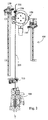
- a conductor is fed by a lead feeding device 300 with the processing conductor material 200 fed.
- the towing gripper 130 is open and retracted. He is located at the beginning of the line, ie in the vicinity of the conductor feed device 300.
- the leveling gripper 140 is also open and located near the winding device 150.
- the winding pot 152 is in the basic position, the winding pot valve is switched off.
- the drag gripper 130 engages, as shown in Figure 1, then the conductor material 200 about 10 mm behind the front Lead end 201 after the lead advancing device 300 this front line end 201 advanced by about 90 mm Has. (A)
- the towing gripper 130 is at a constant tensile force switched, in the embodiment described here a tensile force of about 30 N. Then, the line 200 through the lead feeding device 300 - in the embodiment about 850 mm - advanced, the towing gripper 130th not the actual feed, but only the removal of the advanced conductor material 200. (B)
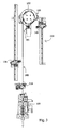
- the towing gripper 130 After about 200 mm of travel, the towing gripper 130 is extended by approx. 80 mm outwards, so as not to move with the winding pot gripper 154 disturbing to interfere. This will be a lateral distance between the drag gripper 130 and the Winding pot gripper 154 complied with. This move will in the present embodiment by a valve - "Valve on" - controlled. Alternatively, but also the Transfer of the front end 201 performed before the winding pot be, so that the avoidance of interference by adhering to a longitudinal distance becomes. Furthermore, alternatively, it may be proposed that Tow gripper 130 to move upwards, so a vertical Keep distance to the winding pot gripper 154. As soon as the towing gripper 130 passes through the winding pot gripper 154 has, the tow gripper is back in the old line procedure - "valve off".
- the winding pot gripper 154 now begins to wind the line on the winding pot 152 with a constant tensile force-again 30 N in the exemplary embodiment.
- the winding pot gripper 154 in turn does not provide the actual feed, but only the removal of the advanced conductor material 200. This process is not really limited.
- the length to be wound is freely adjustable, in the embodiment of about 1500 mm to about 10000 mm, this area can of course also be extended by smaller dimensional changes.
- the speed of the line feed is adjustable in the device described here from 1 m / s to about 5 m / s, while the acceleration in the range of 5 m / s 2 to about 15 m / s 2 , whereby these areas are smaller Changes can of course be extended.
- the towing gripper 130 is moved back to the starting position.
- the towing gripper 130 is a constant tensile force switched, in the present embodiment amounts the tensile force 20 N.
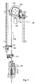
- the winding pot 152 is rotated until the Winding pot gripper 154 a transfer position to the leveling grapple 140 occupies, as shown in Figure 4. (G)
- the leveling gripper 140 is closed and the winding pot gripper open. (H)
- the towing gripper 130 and the leveling gripper 140 in each case a constant traction connected, in the present Embodiment, the tensile force is unequal and is 15 N or 25 N.
- the winding pot 152 is rotated, As shown in Figure 5, to the conductor ends 201 and 202 have reached the same position. This condition will calculated from the position of towing gripper 130 and Level gripper 140 and the respective line projection - In the present embodiment, in each case 10 mm.
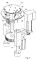
- the winding device shown in detail in Figure 7 150 primarily comprises one by a drive means 170 driven winding pot 152 and the winding gripper 154 with a - at least during the winding process Fixed azimuthal relationship to the winding pot 152. Also this mechanism is realized so that it is not itself provides for the advance of the conductor 200, but only for the regulated and tightly guided removal, ie the Winding process. Furthermore, he is also set up that the - in this case azimuthal - position to each Time of said - and not shown in the figures - Control unit is known.
- the winding device 150 is by a lowering and lifting device 172 adjustable in height.
- her normal Function state is the winding device in an upper position in which the conductor material to be wound is wound on the winding pot 152.
- a lower position is provided in the event that the device not used for wrapping, but - this makes it versatile - to use the towing hook 130, e.g. for cable pieces where the radius of curvature does not play a significant role.
- the winding pot 152 is through the four horizontally hinged variable elements 180, 182, 184 and 186 set up in the unfolded Condition of these elements 180, 182, 184 and 186 of the winding process is performed while in the folded state the wound conductor material relaxed and upwards becomes free. This can be seen in FIG.
- the drive the folding mechanism is in the present embodiment pneumatic.
- a helically shaped guide plate 158th Under the actual winding plane of the winding device 150 is a helically shaped guide plate 158th arranged with an azimuthal length of about 300 °, the should ensure that the Wicketopfgreifer 154 not with the already wound on the winding wire conductor material 200 interferes.
- Above the guide plate are on the horizontally hingedly changeable elements 180, 182, 184 and 186 securing elements 180a, 182a, 184a and 186a arranged to prevent the wound up Conductor material can slip upwards.
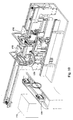
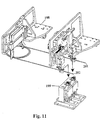
- the upper portion of the winding device has two opposite Recesses 190 and 192 on. These have the Purpose that the finished coil gripped by the unit 198 and can be raised, then transported on to become, as shown in Figure 10. This unit 198 has in the present embodiment, even the Function, this winding to a setting unit 196 too transfer. The coil is then transferred to the transfer carriage 199 a mounting system for further processing passed (FIG 11).
- the Wickeltopfgreifer 154 corresponds in its construction and its function essentially the towing gripper 130 and the leveling gripper 140. However, the Wickeltopfgreifer 154 connected to the winding device 150, that his towing process is azimuthal and he thus the Material wound on the winding pot 152.
- the in both Directions rotatable winding device is equipped with a control device connected so that there the azimuthal position e.g. the winding gripper is known at any time.
Landscapes
- Physics & Mathematics (AREA)
- Engineering & Computer Science (AREA)
- Manufacturing & Machinery (AREA)
- General Physics & Mathematics (AREA)
- Optics & Photonics (AREA)
- Manufacture Of Motors, Generators (AREA)
Description
- Fig. 1
- eine Übersichtsdarstellung der erfindungsgemässen Vorrichtung mit einer - nicht unbedingt zur Erfindung gehörenden - Zuführeinrichtung für Lichtwellenleiter; in dieser Figur ist zudem die Übergabe des vorderen Endes des Lichtwellenleiters an eine erste Greifereinrichtung dargestellt;
- Fig. 2
- eine weitere Darstellung der erfindungsgemässen Vorrichtung gemäss Figur 1; in dieser Figur ist zudem die Übergabe des vorderen Endes des Lichtwellenleiters an den Wickelgreifer dargestellt;
- Fig. 3
- eine weitere Darstellung der erfindungsgemässen Vorrichtung gemäss Figur 1 und 2; in dieser Figur ist zudem der Wickelbetrieb dargestellt;
- Fig. 4
- eine weitere Darstellung der erfindungsgemässen Vorrichtung gemäss Figur 1; in dieser Figur ist zudem das Ablängen und die Übergabe des hinteren Endes des Lichtwellenleiters an die erste Greifeinrichtung und die Übergabe des vorderen Endes des Lichtwellenleiters an eine zweite Greifeinrichtung dargestellt;
- Fig. 5
- eine weitere Darstellung der erfindungsgemässen Vorrichtung gemäss Figur 1; in dieser Figur ist zudem der Prozess des Nivellierens der beiden Enden des Lichtwellenleiters dargestellt;
- Fig. 6
- eine Komponentendarstellung der Wickeleinheit der erfindungsgemässen Vorrichtung mit der ersten und der zweiten Greifeinrichtung (Schleppgreifer und Nivelliergreifer);
- Fig. 7
- eine Detaildarstellung der Wickeleinheit nach Figur 6;
- Fig. 8
- eine Detaildarstellung der Greifer nach Figur 6 (Schleppgreifer und Nivelliergreifer) ;
- Fig. 9
- eine Detaildarstellung des Wickeltopfes nach Figur 6 mit Führungsblech und Entspannungseinrichtung;
- Fig. 10
- eine Übersichtszeichnung der Vorrichtung nach Figur 1, in der jedoch noch weitere Komponenten enthalten sind; Detaildarstellung des Wickeltopfes nach Figur 6 mit Führungsblech und Entspannungseinrichtung und
- Fig. 11
- eine Darstellung einer Transfereinrichtung zur Weiterreichung der fertig gewickelten Spule mit nivellierten Enden.
Claims (10)
- Vorrichtung (100) zum Wickeln eines kabelförmigen Materials (200) miteiner Wickeleinrichtung (150), auf der das kabelförmige Material aufgewickelt werden kann,einer ersten Greifeinrichtung (130) zum linearen Vorschub des vorderen Endes des kabelförmigen Materials (200) und zur Übergabe an die Wickeleinrichtung (150), dadurch gekennzeichnet, daß eine zweite Greifeinrichtung (140) vorhanden istzur Übernahme des genannten vorderen Endes des kabelförmigen Materials von der Wickeleinrichtung (150) und zur linearen Bewegung dieses vorderen Endes von der Wickeleinrichtung (150) weg, wobeidie genannte erste Greifeinrichtung (130) dafür eingerichtet ist, das hintere Ende des kabelförmigen Materials (200) zu greifen und im Zusammenspiel mit der zweiten Greifeinrichtung auf eine vorbestimmte Differenz der Enden zu nivellieren.
- Vorrichtung nach Anspruch 1, dadurch gekennzeichnet, dass die Wickeleinrichtung (150) einen Wickelgreifer (154) aufweist, der so eingerichtet ist, dass mit ihm der Wickelvorgang auf einem Wickeltopf (152) durchgeführt werden kann.
- Vorrichtung nach Anspruch 1 oder 2, dadurch gekennzeichnet, dass die Wickeleinrichtung (150) Mittel (180, 182, 184, 186) aufweist, mit dem die Wicklung festgeklemmt und gelöst werden kann.
- Vorrichtung nach Anspruch 3, dadurch gekennzeichnet, dass die Mittel (180, 182, 184, 186), mit dem die Wicklung festgeklemmt und gelöst werden kann, Sicherungsmittel (180a, 182a, 184a, 186a) aufweisen, die bewirken, dass die Wicklung nach oben begrenzt wird.
- Vorrichtung nach einem der vorstehenden Ansprüche, gekennzeichnet durch ein Führungsmittel (158) zur vertikalen Führung der Wicklung auf der Wickeleinrichtung (150) und zur Vermeidung von Störungen der Wicklung durch den Wickeltopfgreifer (154).
- Vorrichtung nach einem der vorstehenden Ansprüche, dadurch gekennzeichnet, dass der obere Bereich der Wickeleinrichtung (150) zwei gegenüberliegende Ausnehmungen (190, 192) zum Abbinden und Weitertransport der gewickelten Spule aufweist.
- Verfahren zum Wickeln eines kabelförmigen Leitermaterials (200) miteiner Wickeleinrichtung (150), auf der das kabelförmige. Leitermaterial aufgewickelt werden kann, mit einem Wickeltopfgreifer (154),einer ersten Greifeinrichtung (130) zum linearen Vorschub des vorderen Endes (201) des kabelförmigen Leitermaterials (200) und zur Übergabe an die Wickeleinrichtung (150),einer zweiten Greifeinrichtung (140) zur Übernahme des genannten vorderen Endes (201) des kabelförmigen Leitermaterials von der Wickeleinrichtung (150) und zur linearen Bewegung dieses vorderen Endes von der Wickeleinrichtung (150) weg, mit den Schritten(A) Übergabe des vorderen Endes (201) des kabelförmigen Materials an die erste Greifereinrichtung (130),(B) Vorschub des vorderen Endes (201) des kabelförmigen Leitermaterials (200) und Führung durch die erste Greifeinrichtung (130),(C) Übergabe des vorderen Endes (201) des kabelförmigen Materials an den Wickeltopfgreifer (154);(D) Wickeln des kabelförmigen Leitermaterials (200) auf der Wickeleinrichtung (150),(E) Übergabe des hinteren Endes (202) des kabelförmigen Leitermaterials (200) an die erste Greifeinrichtung (130),(F) Ablängen des kabelförmigen Leitermaterials (200),(H) Übergabe des vorderen Endes (201) des kabelförmigen Leitermaterials an die zweite Greifeinrichtung (140),(I) Nivellieren der beiden Enden (201, 202) des kabelförmigen Leitermaterials (200) durch eine Ausrichtung der ersten Greifereinrichtung (130) mit der zweiten Greifereinrichtung (140),(J) Entspannen der Wicklung auf der Wickeleinrichtung (150, 152).
- Verfahren nach Anspruch 7, gekennzeichnet durch den zusätzlichen Schritt, den Wickeltopf nach dem Entspannen (J) in eine Wickelentnahmeposition zu drehen.
- Verfahren nach Anspruch 7 oder 8, gekennzeichnet durch den zusätzlichen Schritt, nach dem Ablängen (F) des kabelförmigen Leitermaterials (200) den Wickeltopf (152) zu drehen, bis der Wickeltopfgreifer (154) eine Übergabeposition zur zweiten Greifereinrichtung (140) einnimmt.
- Verfahren nach einem der Ansprüche 7 bis 9, dadurch gekennzeichnet, dass die erste Greifereinrichtung (130) für einen bestimmten Teil des Fahrweges aus der Längsrichtung herausbewegt wird, um eine störende Interferenz mit dem Wickeltopfgreifer (154) zu vermeiden und wieder in die ursprüngliche Fahrlinie hereinbewegt wird, nachdem die erste Greifereinrichtung (130) den Wickeltopfgreifer (154) passiert hat.
Priority Applications (3)
| Application Number | Priority Date | Filing Date | Title |
|---|---|---|---|
| EP02405636A EP1387449B1 (de) | 2002-07-22 | 2002-07-22 | Vorrichtung und Verfahren zum Wickeln von kabelförmigem Material |
| DE50202922T DE50202922D1 (de) | 2002-07-22 | 2002-07-22 | Vorrichtung und Verfahren zum Wickeln von kabelförmigem Material |
| US10/622,481 US6948675B2 (en) | 2002-07-22 | 2003-07-21 | Apparatus and process for winding cable-like material |
Applications Claiming Priority (1)
| Application Number | Priority Date | Filing Date | Title |
|---|---|---|---|
| EP02405636A EP1387449B1 (de) | 2002-07-22 | 2002-07-22 | Vorrichtung und Verfahren zum Wickeln von kabelförmigem Material |
Publications (2)
| Publication Number | Publication Date |
|---|---|
| EP1387449A1 EP1387449A1 (de) | 2004-02-04 |
| EP1387449B1 true EP1387449B1 (de) | 2005-04-27 |
Family
ID=30011303
Family Applications (1)
| Application Number | Title | Priority Date | Filing Date |
|---|---|---|---|
| EP02405636A Expired - Lifetime EP1387449B1 (de) | 2002-07-22 | 2002-07-22 | Vorrichtung und Verfahren zum Wickeln von kabelförmigem Material |
Country Status (3)
| Country | Link |
|---|---|
| US (1) | US6948675B2 (de) |
| EP (1) | EP1387449B1 (de) |
| DE (1) | DE50202922D1 (de) |
Cited By (9)
| Publication number | Priority date | Publication date | Assignee | Title |
|---|---|---|---|---|
| EP1987897A1 (de) | 2007-05-04 | 2008-11-05 | komax Holding AG | Einrichtung und Verfahren zur Übernahme eines zu einem Wickel geformten Kabelabschnittes |
| EP1988044A1 (de) | 2007-05-04 | 2008-11-05 | komax Holding AG | Wickler und Verfahren zum Herstellen eines Wickels |
| EP1988045A1 (de) | 2007-05-04 | 2008-11-05 | komax Holding AG | Kabelbearbeitungsmaschine und Verfahren zur Herstellung und Bearbeitung eines Kabelabschnittes |
| DE202007013417U1 (de) | 2007-09-24 | 2009-02-12 | Schleuniger Holding Ag | Vorrichtung zur Herstellung langer, konfektionierter, elektrischer Leitungen in einem CrimpCenter |
| WO2009040749A2 (en) | 2007-09-24 | 2009-04-02 | Schleuniger Holding Ag | Method of and apparatus for producing long, assembled, electric cables |
| DE112009001308T5 (de) | 2008-07-01 | 2011-05-12 | Schleuniger Holding Ag | Vorrichtung und Verfahren zum Abbinden von ringförmigem Wickelgut |
| EP3020671A1 (de) | 2014-11-17 | 2016-05-18 | Lisa Dräxlmaier GmbH | Methode und Vorrichtung zum Sammeln einer Leitung |
| EP3020672A1 (de) | 2014-11-17 | 2016-05-18 | Lisa Dräxlmaier GmbH | Vorrichtung zum Aufwickeln eines biegeschlaffen strangförmigen Elements und Verfahren dazu |
| DE102015220693A1 (de) | 2015-10-22 | 2017-04-27 | Lisa Dräxlmaier GmbH | Vorrichtung zum Legen eines biegeschlaffen, strangförmigen Elements und Verfahren dazu |
Families Citing this family (12)
| Publication number | Priority date | Publication date | Assignee | Title |
|---|---|---|---|---|
| JP5528433B2 (ja) | 2008-05-20 | 2014-06-25 | シュロニガー ホールディング アーゲー | ケーブル搬送装置 |
| WO2010001342A1 (en) * | 2008-07-01 | 2010-01-07 | Schleuniger Holding Ag | Apparatus and method for coiling cable or wire pieces to give a coil having two further processable ends |
| CN102074877A (zh) * | 2011-01-23 | 2011-05-25 | 常州三恒电器有限公司 | 铜导线生产工艺 |
| WO2013068984A1 (de) * | 2011-11-11 | 2013-05-16 | Schleuniger Holding Ag | Fördereinrichtung für leitungen |
| KR101975072B1 (ko) | 2011-11-11 | 2019-05-03 | 쉴로이니게르 홀딩 아게 | 트위스팅 장치 |
| MX2014005602A (es) | 2011-11-11 | 2015-01-19 | Schleuniger Holding Ag | Dispositivo recolector de cable (apilador de alambre). |
| PT2801984T (pt) | 2013-05-08 | 2019-01-23 | Schleuniger Holding Ag | Prendedor, cabeça de torção e dispositivo de torção |
| US10023426B2 (en) | 2014-05-12 | 2018-07-17 | Curti Costruzioni Meccaniche S.P.A. | Coil making apparatus and method |
| JP6507189B2 (ja) * | 2017-03-08 | 2019-04-24 | 矢崎総業株式会社 | 電線処理装置及び電線処理方法 |
| CN107963510A (zh) * | 2017-11-28 | 2018-04-27 | 珠海市恒诺科技有限公司 | 加金线装置 |
| CN111650708B (zh) * | 2020-06-24 | 2022-04-19 | 网建通信建设有限公司 | 一种光缆固定装置及其敷设方法 |
| CN113928667B (zh) * | 2020-07-13 | 2023-05-12 | 泰科电子(上海)有限公司 | 线缆盘绕系统 |
Family Cites Families (9)
| Publication number | Priority date | Publication date | Assignee | Title |
|---|---|---|---|---|
| DE2636974A1 (de) * | 1976-08-17 | 1978-02-23 | Wolfgang Freitag | Vorrichtung zum wickeln von kabellaengen |
| DE3343286A1 (de) * | 1983-11-30 | 1985-06-05 | Licentia Patent-Verwaltungs-Gmbh, 6000 Frankfurt | Verfahren und anordnung zum aufspulen eines wickelguts |
| DE3443754A1 (de) * | 1984-11-30 | 1986-06-12 | Deißenberger, Hans, 7240 Horb | Verfahren zum ablaengen von kabelfoermigen wickelgut und vorrichtung zu dessen durchfuehrung |
| FR2678135B1 (fr) * | 1991-06-21 | 1993-10-22 | Entreprise Industrielle | Procede et dispositif de fabrication de faisceaux electriques. |
| DE4235007C2 (de) * | 1992-10-16 | 1996-10-31 | Fraunhofer Ges Forschung | Vorrichtung zum Wickeln und Abbinden von Kabeln, Litzen oder dgl. Wickelmaterial |
| US5427327A (en) * | 1993-09-27 | 1995-06-27 | At&T Corp. | Method and apparatus for capturing and positioning a cable |
| US6135164A (en) * | 1997-09-29 | 2000-10-24 | Komax Holding Ag | Apparatus and method for preparing wires in a harness making machine |
| US6669129B1 (en) * | 2001-08-31 | 2003-12-30 | Stocker Yale, Inc. | Fiber optic cable winding tool |
| US6554217B1 (en) * | 2001-08-31 | 2003-04-29 | Stocker Yale, Inc. | Fiber optic cable winding tool |
-
2002
- 2002-07-22 DE DE50202922T patent/DE50202922D1/de not_active Expired - Lifetime
- 2002-07-22 EP EP02405636A patent/EP1387449B1/de not_active Expired - Lifetime
-
2003
- 2003-07-21 US US10/622,481 patent/US6948675B2/en not_active Expired - Lifetime
Cited By (11)
| Publication number | Priority date | Publication date | Assignee | Title |
|---|---|---|---|---|
| EP1987897A1 (de) | 2007-05-04 | 2008-11-05 | komax Holding AG | Einrichtung und Verfahren zur Übernahme eines zu einem Wickel geformten Kabelabschnittes |
| EP1988044A1 (de) | 2007-05-04 | 2008-11-05 | komax Holding AG | Wickler und Verfahren zum Herstellen eines Wickels |
| EP1988045A1 (de) | 2007-05-04 | 2008-11-05 | komax Holding AG | Kabelbearbeitungsmaschine und Verfahren zur Herstellung und Bearbeitung eines Kabelabschnittes |
| DE202007013417U1 (de) | 2007-09-24 | 2009-02-12 | Schleuniger Holding Ag | Vorrichtung zur Herstellung langer, konfektionierter, elektrischer Leitungen in einem CrimpCenter |
| WO2009040749A2 (en) | 2007-09-24 | 2009-04-02 | Schleuniger Holding Ag | Method of and apparatus for producing long, assembled, electric cables |
| DE112008002501T5 (de) | 2007-09-24 | 2010-10-21 | Schleuniger Holding Ag | Verfahren und Vorrichtung zur Herstellung langer, konfektionierter, elektrischer Leitungen |
| DE112009001308T5 (de) | 2008-07-01 | 2011-05-12 | Schleuniger Holding Ag | Vorrichtung und Verfahren zum Abbinden von ringförmigem Wickelgut |
| EP3020671A1 (de) | 2014-11-17 | 2016-05-18 | Lisa Dräxlmaier GmbH | Methode und Vorrichtung zum Sammeln einer Leitung |
| EP3020672A1 (de) | 2014-11-17 | 2016-05-18 | Lisa Dräxlmaier GmbH | Vorrichtung zum Aufwickeln eines biegeschlaffen strangförmigen Elements und Verfahren dazu |
| DE102015220693A1 (de) | 2015-10-22 | 2017-04-27 | Lisa Dräxlmaier GmbH | Vorrichtung zum Legen eines biegeschlaffen, strangförmigen Elements und Verfahren dazu |
| DE102015220693B4 (de) | 2015-10-22 | 2018-03-22 | Lisa Dräxlmaier GmbH | Vorrichtung zum Legen eines biegeschlaffen, strangförmigen Elements und Verfahren dazu |
Also Published As
| Publication number | Publication date |
|---|---|
| US6948675B2 (en) | 2005-09-27 |
| DE50202922D1 (de) | 2005-06-02 |
| EP1387449A1 (de) | 2004-02-04 |
| US20040104296A1 (en) | 2004-06-03 |
Similar Documents
| Publication | Publication Date | Title |
|---|---|---|
| EP1387449B1 (de) | Vorrichtung und Verfahren zum Wickeln von kabelförmigem Material | |
| DE3809635C3 (de) | Verfahren und Vorrichtung zur Herstellung eines spulenlosen Gebindes sowie ein mit dem Verfahren hergestelltes Gebinde | |
| DE3802900C2 (de) | ||
| DE3244925A1 (de) | Spulentransportvorrichtung | |
| DE3015846A1 (de) | Verfahren und vorrichtung zum automatischen positionieren der enden von drahtabschnitten | |
| DE19533833B4 (de) | Kreuzspulenwechseleinrichtung einer Kreuzspulen herstellenden Textilmaschine | |
| EP0540893A1 (de) | Vorrichtung zum Verseilen von strangförmigem Gut insbesondere grösseren Querschnittes mit wechselnder Schlagrichtung | |
| DE102012005374A1 (de) | Spulenwechselvorrichtung | |
| DE3833958C2 (de) | Vorrichtung zum Aufspulen von drahtförmigem Gut auf zweiflanschige Spulen | |
| DE3320250A1 (de) | Verfahren zum weiterverarbeiten von mit hilfe eines flyers aufgewickeltem strangfoermigen gut | |
| DE10354847A1 (de) | Vorrichtung und Verfahren zum Aufwickeln nicht zur Verarbeitung vorgesehener Materialstreifen | |
| DE102017120650A1 (de) | Vorrichtung zum Beschichten von Behältern mittels eines Beschichtungsverfahrens und Verfahren zum Betrieb einer solchen Vorrichtung | |
| DE2742662A1 (de) | Verfahren und vorrichtung zur kontinuierlichen verseilung von strangfoermigem gut groesseren querschnitts | |
| DE19621151B4 (de) | Vorrichtung zum Transportieren von Garnspulen | |
| DE4029464A1 (de) | Verfahren und vorrichtung zum austragen von auflaufspulen aus einer streck-falschdrahtzwirnmaschine | |
| DE19649759C2 (de) | Verfahren zum Herstellen von verdrillten Leitungen sowie Vorrichtung zum Durchführen des Verfahrens | |
| DE10239334B4 (de) | Fadenspulmaschine mit einem Spannungsdetektor | |
| DE19614585A1 (de) | Verfahren und Vorrichtung zur Herstellung von Kabelringen, Drahtringen und dergleichen | |
| DE2651225A1 (de) | Verfahren und vorrichtung zum aufwickeln oder aufspulen von draht o.dgl. | |
| EP0844704A2 (de) | Verfahren zum Herstellen von verdrillten, konfektionierten leitungen sowie Vorrichtung zum Durchführen des Verfahrens | |
| DE102016012510A1 (de) | Modulare Einrichtung zur automatischen Bestimmung von Eigenschaften von länglichen Textilmustern in der Art von Garnen, Fäden, Bändern und Ähnlichem | |
| DE1153676B (de) | Verfahren und Vorrichtung zum selbsttaetigen Abbinden von in Walzwerken od. dgl. anfallenden Buendeln oder Ringen | |
| DE3438212A1 (de) | Anlage zum ablaengen und wickeln von wickelgut | |
| DE1540543C3 (de) | Vorrichtung zum diskontinuierlichen Aufspritzen von Distanzscheiben auf Innenleiter für Koaxialpaare | |
| EP1918435B1 (de) | Musterkettenschärmaschine |
Legal Events
| Date | Code | Title | Description |
|---|---|---|---|
| GRAH | Despatch of communication of intention to grant a patent |
Free format text: ORIGINAL CODE: EPIDOS IGRA |
|
| GRAS | Grant fee paid |
Free format text: ORIGINAL CODE: EPIDOSNIGR3 |
|
| PUAI | Public reference made under article 153(3) epc to a published international application that has entered the european phase |
Free format text: ORIGINAL CODE: 0009012 |
|
| 17P | Request for examination filed |
Effective date: 20030228 |
|
| AK | Designated contracting states |
Kind code of ref document: A1 Designated state(s): AT BE BG CH CY CZ DE DK EE ES FI FR GB GR IE IT LI LU MC NL PT SE SK TR |
|
| AX | Request for extension of the european patent |
Extension state: AL LT LV MK RO SI |
|
| AKX | Designation fees paid |
Designated state(s): CH DE FR GB IT LI |
|
| GRAA | (expected) grant |
Free format text: ORIGINAL CODE: 0009210 |
|
| AK | Designated contracting states |
Kind code of ref document: B1 Designated state(s): CH DE FR GB IT LI |
|
| REG | Reference to a national code |
Ref country code: GB Ref legal event code: FG4D Free format text: NOT ENGLISH |
|
| REG | Reference to a national code |
Ref country code: CH Ref legal event code: EP |
|
| REG | Reference to a national code |
Ref country code: IE Ref legal event code: FG4D Free format text: LANGUAGE OF EP DOCUMENT: GERMAN |
|
| REF | Corresponds to: |
Ref document number: 50202922 Country of ref document: DE Date of ref document: 20050602 Kind code of ref document: P |
|
| REG | Reference to a national code |
Ref country code: CH Ref legal event code: NV Representative=s name: R. A. EGLI & CO. PATENTANWAELTE |
|
| GBT | Gb: translation of ep patent filed (gb section 77(6)(a)/1977) |
Effective date: 20050629 |
|
| PLBE | No opposition filed within time limit |
Free format text: ORIGINAL CODE: 0009261 |
|
| STAA | Information on the status of an ep patent application or granted ep patent |
Free format text: STATUS: NO OPPOSITION FILED WITHIN TIME LIMIT |
|
| ET | Fr: translation filed | ||
| 26N | No opposition filed |
Effective date: 20060130 |
|
| PGFP | Annual fee paid to national office [announced via postgrant information from national office to epo] |
Ref country code: GB Payment date: 20080722 Year of fee payment: 7 |
|
| GBPC | Gb: european patent ceased through non-payment of renewal fee |
Effective date: 20090722 |
|
| PG25 | Lapsed in a contracting state [announced via postgrant information from national office to epo] |
Ref country code: GB Free format text: LAPSE BECAUSE OF NON-PAYMENT OF DUE FEES Effective date: 20090722 |
|
| REG | Reference to a national code |
Ref country code: FR Ref legal event code: PLFP Year of fee payment: 15 |
|
| REG | Reference to a national code |
Ref country code: FR Ref legal event code: PLFP Year of fee payment: 16 |
|
| REG | Reference to a national code |
Ref country code: FR Ref legal event code: PLFP Year of fee payment: 17 |
|
| PGFP | Annual fee paid to national office [announced via postgrant information from national office to epo] |
Ref country code: FR Payment date: 20210727 Year of fee payment: 20 Ref country code: IT Payment date: 20210727 Year of fee payment: 20 |
|
| PGFP | Annual fee paid to national office [announced via postgrant information from national office to epo] |
Ref country code: DE Payment date: 20210721 Year of fee payment: 20 |
|
| PGFP | Annual fee paid to national office [announced via postgrant information from national office to epo] |
Ref country code: CH Payment date: 20211028 Year of fee payment: 20 |
|
| REG | Reference to a national code |
Ref country code: DE Ref legal event code: R071 Ref document number: 50202922 Country of ref document: DE |
|
| REG | Reference to a national code |
Ref country code: CH Ref legal event code: PL |