EP1988044A1 - Wickler und Verfahren zum Herstellen eines Wickels - Google Patents
Wickler und Verfahren zum Herstellen eines Wickels Download PDFInfo
- Publication number
- EP1988044A1 EP1988044A1 EP08155332A EP08155332A EP1988044A1 EP 1988044 A1 EP1988044 A1 EP 1988044A1 EP 08155332 A EP08155332 A EP 08155332A EP 08155332 A EP08155332 A EP 08155332A EP 1988044 A1 EP1988044 A1 EP 1988044A1
- Authority
- EP
- European Patent Office
- Prior art keywords
- winder
- cable
- winding
- fingers
- finger
- Prior art date
- Legal status (The legal status is an assumption and is not a legal conclusion. Google has not performed a legal analysis and makes no representation as to the accuracy of the status listed.)
- Granted
Links
- 238000004519 manufacturing process Methods 0.000 title claims abstract description 11
- 238000000034 method Methods 0.000 title claims abstract description 11
- 238000004804 winding Methods 0.000 claims description 64
- 230000033001 locomotion Effects 0.000 claims description 16
- 238000012545 processing Methods 0.000 description 41
- 239000002390 adhesive tape Substances 0.000 description 20
- 238000000151 deposition Methods 0.000 description 13
- 238000012546 transfer Methods 0.000 description 12
- 239000012790 adhesive layer Substances 0.000 description 6
- 239000000853 adhesive Substances 0.000 description 4
- 230000001070 adhesive effect Effects 0.000 description 4
- 238000005452 bending Methods 0.000 description 3
- 238000002788 crimping Methods 0.000 description 3
- 210000000078 claw Anatomy 0.000 description 2
- 239000002131 composite material Substances 0.000 description 2
- 238000007906 compression Methods 0.000 description 2
- 230000006835 compression Effects 0.000 description 2
- 238000003780 insertion Methods 0.000 description 2
- 230000037431 insertion Effects 0.000 description 2
- 239000010410 layer Substances 0.000 description 2
- 239000013307 optical fiber Substances 0.000 description 2
- 238000000926 separation method Methods 0.000 description 2
- 238000003860 storage Methods 0.000 description 2
- 230000001360 synchronised effect Effects 0.000 description 2
- RYGMFSIKBFXOCR-UHFFFAOYSA-N Copper Chemical compound [Cu] RYGMFSIKBFXOCR-UHFFFAOYSA-N 0.000 description 1
- 230000015572 biosynthetic process Effects 0.000 description 1
- 239000004020 conductor Substances 0.000 description 1
- 229910052802 copper Inorganic materials 0.000 description 1
- 239000010949 copper Substances 0.000 description 1
- 230000008878 coupling Effects 0.000 description 1
- 238000010168 coupling process Methods 0.000 description 1
- 238000005859 coupling reaction Methods 0.000 description 1
- 230000001419 dependent effect Effects 0.000 description 1
- 238000011161 development Methods 0.000 description 1
- 230000018109 developmental process Effects 0.000 description 1
- 238000005304 joining Methods 0.000 description 1
- 238000003754 machining Methods 0.000 description 1
- 238000005259 measurement Methods 0.000 description 1
Images


Classifications
-
- B—PERFORMING OPERATIONS; TRANSPORTING
- B65—CONVEYING; PACKING; STORING; HANDLING THIN OR FILAMENTARY MATERIAL
- B65H—HANDLING THIN OR FILAMENTARY MATERIAL, e.g. SHEETS, WEBS, CABLES
- B65H54/00—Winding, coiling, or depositing filamentary material
- B65H54/56—Winding of hanks or skeins
-
- B—PERFORMING OPERATIONS; TRANSPORTING
- B65—CONVEYING; PACKING; STORING; HANDLING THIN OR FILAMENTARY MATERIAL
- B65H—HANDLING THIN OR FILAMENTARY MATERIAL, e.g. SHEETS, WEBS, CABLES
- B65H2701/00—Handled material; Storage means
- B65H2701/30—Handled filamentary material
- B65H2701/34—Handled filamentary material electric cords or electric power cables
Definitions
- the invention relates to a winder and a method for producing a winding having at least one turn, wherein a arranged on a rotatable Wicklerteller Wicklergreifer holds the leading end of a cable section and the winder plate peripherally arranged fingers form the cable section to the winding according to the definition of the independent claims.
- the publication DE 42 35 007 A1 discloses a winding device for cable sections, in which the inner walls of a drum serve as contact surfaces for the formation of the coil and thus predetermine the outer diameter of the roll.
- the drum remains at rest during the insertion of the cable and is opened after reaching the cable length and setting of the coil. After the transfer of the two cable ends of the roll to transfer gripper subsequent cable finishing, such as crimping and / or grommets put on, feasible.
- disadvantages are also to be mentioned, such as, for example, uncontrollable bending radii during insertion and compression of the various winding layers for setting. Whether the individual wraps always rest against the wall is uncertain. Minimum bending radii when entering and exiting the cable into or out of the drum are also not given.
- the font WO 03/018456 A1 discloses a winding device for a cable with a rotating winding mandrel, are arranged in the hanging and spreadable winding arms. Depending on the cable section, the arms are more or less spread so that after reaching the cable length approximately both cable ends are the same length. For the processing of the cable ends, the winding is taken over after setting of transfer grippers.
- the invention aims to remedy this situation.
- the invention as characterized in the main claims, solves the problem of providing a device and a method for producing long cable sections without prolonging the entire processing time.
- the inventive device is particularly suitable for cable processing machines with swivel arms.
- the inventive device can also be used in transfer machines with linearly movable transport units, if additional grippers and transfer devices for handling the cable ends and the cable winding are provided.
- the winder is arranged between a separating / detaching unit and a second pivoting arm.
- the winding of the cable section is effected by means of a winding plate, which is rotatable by means of a controlled motor in response to a likewise motor-driven belt drive, the belt drive is the cable feed and the length measurement of the advanced cable.
- This arrangement is particularly advantageous for elastic cables.
- the leading cable end of the cable to be wound is by means of Edited processing stations and after processing by means of a first swivel arm swung back to the separation / Abisolieraji and advanced with the tape drive a short length, the winder can grab the leading cable end.
- the tape drive advances the cable to the desired length of the cable section and the winder winds the advanced cable simultaneously to a reel.
- a linearly displaceable depositing unit grips the winding.
- the winder disc relaxes its clamping fingers pneumatically and moves pneumatically to the rear. Shims act as scrapers prevent pulling the coil to the rear.
- the laying unit moves back with the winding so that the trailing end of the cable can be separated and stripped and, if necessary, machined, with a second pivot arm feeding the trailing end of the cable to processing stations.
- Grippers of the depositing unit hold the winding and the depositing unit moves to about below the pivot point of the second pivot arm and the trailing end of the cable can, if necessary, be pulled out of the winding for the processing of its end by means of the second pivot arm.
- the depositing unit moves further in the cable feed direction for storage.
- the winding can be provided with a joinery.
- the winding may be provided with the joinery during processing of the trailing cable end or during processing of the leading cable end of the next cable section.
- the set winding can then be dispensed into containers, on conveyor belts or other receiving means, such as mandrels.
- the advantages achieved by the invention are essentially to be seen in the fact that the Abbindvorgang takes place on the winding time parallel to the processing operation on the cable section.
- the total processing time for the cable section also called machine cycle time, not extended.
- the total processing time remains the same with or without joinery.
- the time for making the coil is comparable to the time taken to deposit a stretched cable section in a conventional cable processing machine.
- the winder and the depositing unit are not connected as a separate device to the cable processing machine but form an integral unit of the cable processing machine.
- the manufactured and to be processed cable section is cut from the cable stock, processed at the leading end of the cable, wound up, possibly processed at the trailing cable end and handed over as a winding with Abbund the tray without manual intervention is necessary.
- the cable processing machine builds short in spite of long cable sections compared to a conventional cable processing machine.
- the length of the cable processing machine is not determined by the length of the cable section.
- the cable section is cut to length from a cable supply and processed at the cable ends, wherein a winder is provided which supports the cable section Cable section forms into a winding with at least one turn and provides a laying unit with a Abbind recognized the winding with a Abbund.
- Fig. 1 shows a cable section 1, which is formed with a plurality of turns 3 to a winding 2, wherein the turns 3 are held together by means of a 4 Abb.
- the leading cable end 5 is processed, for example, a crimp contact 6 is possibly struck with a grommet.
- the leading cable end 5 can also only be stripped or not processed.
- the trailing cable end 7 is processed, for example, a crimp contact 8 is possibly struck with a grommet.
- the trailing cable end 7 can only be stripped or not processed.
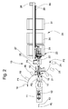
- Fig. 2 shows a cable processing machine 10 in plan and Fig. 3 the cable processing machine 10 in three-dimensional representation.
- a cable feed device consisting of a belt drive 11 and a length measuring device 12.
- the belt drive 11 leads a cable 13 to a first pivot arm 14 with a first gripper 15.
- the tape drive 11 advances the cable 13 and the length measuring device 12 measures the extended cable length, the extended cable length corresponds to the produced and to be processed at the ends cable section.
- the cable supply such as a cable drum or a cable coil.
- the first pivot arm 14 can be placed in a symbolized by an arrow P1 pivoting movement and / or in a symbolized by an arrow P2 linear motion.
- the first pivot arm 14 serves as a feeding device by means of rotary motion P1 and linear movement P2 side of the cable longitudinal axis KL arranged processing stations 16 (for example, crimping presses and / or Tüllenbe Anlagener) with leading cable ends. 5
- the leading cable end 5 brings the first pivot arm 14 by means of gripper 15, the leading cable end 5 back into the cable longitudinal axis KL. Then the cable 13 is advanced by means of belt drive 11 until a winder 17 can reach the leading cable end 5. Thereafter, the tape drive 11 advances the predetermined cable section 1 measured by the length measuring device 12, and the winder 17 synchronized with the tape drive 11 winds the advanced cable section simultaneously to form a reel 2 Fig. 1 on. After the production of the coil 2, the cable section 1 is separated from the cable 13 by means of a separating / Abisolierü with separation / Stripping 18 and / or stripped. The leading cable end of the next cable section is taken by the first pivot arm 14 by means of grippers 15 and fed to the processing stations 16 for processing.
- the trailing cable end 7 of the wound Cable section 1 is taken by a second pivot arm 19 by means of second gripper 20 and placed in a symbolized by an arrow P3 pivoting movement and / or in a symbolized by an arrow P4 linear movement, the trailing cable end 7 laterally of the cable longitudinal axis KL arranged processing stations 21 (for example crimping presses and / or Tüllenbe collaborativeer) is supplied.
- the winding 2 is taken over by winding grippers 22 of a laying unit 23. Thereafter, the depositing unit 23 moves in the direction of cable feed in the direction of a tray 24 until the depositing unit 23 comes to rest approximately below the swivel arm drive 25 of the second swivel arm 19.
- a belt station 26 Before processing the trailing cable end 7, a belt station 26 provides a belt section for the production of the truss 4. The band section is taken over by a setting device 27 of the laying unit 23.
- the trailing cable end 7 of the second arm 19 brings by means of gripper 20, the trailing end of the cable 7 back approximately in the cable longitudinal axis KL and the depositing unit 23 is moved with the winding 2 in the direction of tray 24.
- the joining 4 is produced by means of the binding device 27.
- the winding 2 with Abbund 4 is sorted according to good / bad criteria placed in one or the other container 31 of the tray 24.
- a belt drive 28 moves the laying unit 23 by means of belts 85 along a linear guide 29 arranged on a machine frame 30.
- Fig. 3 the directional arrows x, y and z are entered.
- the cable 13 is advanced by means of the belt drive 11 in the x direction, or the cable longitudinal axis KL is in the x direction.
- the laying unit 23 moves in the x-direction and places the finished roll 2 in the z-direction in the corresponding container 31.
- the winder 17 is for stripping the roll 2 as in Fig. 6 shown movable in the y-direction.
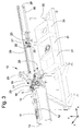
- Fig. 4 shows the winder 17, which forms the cable section 1 to a winding 2.
- a rotatable Wicklerteller 32 support fingers 33 and clamping fingers 34 are circular, peripherally arranged. Support fingers 33 and clamping fingers 34 carry the turns 3 of the coil second Fig. 7 shows details of the fingers 33,34.
- the Wicklerteller 32 lies in the plane spanned by the axes x and z plane and rotates about a horizontal axis of rotation 86 which is parallel to the y-axis. After processing the leading cable end 5 of the tape drive 11 pushes the cable 13 before.
- the roller 35 and a counter-finger 42 are additionally set into a rotational movement P7 by means of a drive unit 43 into a linear movement P6 and the counter-finger 42.
- the roller 35 displaces a guide finger 36 into a rotational movement P5 about a fixed axis 48, wherein the guide finger 36 moves toward the counter-finger 42 and deflects the cable 13 in the direction of an open winder gripper 37 during advancement.
- Guide fingers 36 and counter-fingers 42 also serve as guide aids for laterally guiding the cable 13.
- the winder gripper 37 is arranged on the winder disk 32 within the circle formed by the fingers 33, 34.
- Roller 35, guide finger 36, counter-finger 42 and the Linear movement P6 generating drive unit 43 form the opposite the Wicklerteller 32 fixed cable guide 38.
- the length measuring device 12 measures the extended cable length and the controller stops the belt drive 11 as soon as the cable gripper 37 necessary cable length is reached. Then the winder gripper 37 encompassing the cable end is closed.
- a winder drive 39 drives the Wicklerteller 32, wherein the winder drive 39 and the tape drive 11 are synchronized during manufacture of the coil 2, which advances the tape drive 11 to cable is wound from the Wickler plate 32 at the same time, the turns 3 of the resulting roll 2 on the Fingers 33,34 rest.
- the winding 2 is taken by the winding grippers 22 of the depositing unit 23 and the Wicklerteller 32 moves in the y direction by means of a cylinder 41, wherein a between the fingers 33,34 cross, relative to the Wicklerteller 32 fixedly arranged scraper 40 the winding. 2 from the fingers 33,34 pushes. Details are in Fig. 6 and Fig. 7 shown.
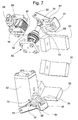
- Fig. 5 shows the back of the winder 17 and Fig. 6
- a motor pulley of the winder drive 39 drives a toothed belt 45 which drives a Wicklerpulley 46 and thus the Wicklerteller 32.
- the Wicklerteller 32 is movable together with the winder drive 39 along linear guides 47 in the y direction by means of cylinder 41 for the purpose of stripping the roll 2 of the fingers 33,34, the winding 2 is present on the fixed scraper 40 and so on the fingers 33, 34 is pushed.
- 49 designates an air connection, via which compressed air can be supplied to pneumatic units (winder gripper 37, clamping finger 34) of the winder disk 32.
- the motor pulley 44 is connected to the winder drive 39 by means of a coupling 50.
- Fig. 7 shows details of the winder 17 in particular arranged on the Wicklerteller 32 pneumatic units such as Wicklergreifer 37 and clamping fingers 34.
- the support fingers 33 carry the turns 3 of the coil 2.
- the clamping fingers 34 carry and hold the turns 3 of the coil 2.
- Each clamping finger 34 points at the free End of a nose 51, which restrain the winding 2 during the winding process.
- the clamping finger 34 is rotatable about an axis 53 by means of a pneumatic drive 52. In the position shown, the winding 2 can be stripped off by the fingers 33, 34 by means of scrapers 40.
- the pneumatic actuator 52 actuated by means of a cylinder 54 about an axis 73 rotatable lever 55 which rotates the clamping finger 34 by means of engaging in slots 56 bolt 57 about the axis 53 until the clamping finger 34 has the same position as the support fingers 33. In this position, the Wicklerteller 32 ready for the winding process.
- Fig. 7 shows the Wicklergreifer 37 for holding the leading cable end 5.
- the two gripper halves 58 shown in the closed position are pneumatically rotatable about an axis 59 and open and engage around by means of fingers 60 the cable end.
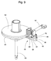
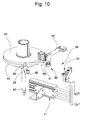
- Fig. 8 to Fig. 10 show a belt station 26 in which an adhesive tape 61 is prepared with one-side applied adhesive layer to a necessary for the Abbund 4 length.
- a tape supply 62 is located on a z-direction by means of cylinder 63 vertically adjustable belt plate 64, which is for the first time, manual threading of the adhesive tape 61 for better accessibility in the upper layer.
- a finger 65 with two finger pins 66 is arranged on the belt plate 64.
- the adhesive tape 61 is on the adhesive-less or dry side manually peeled off the plate-like finger bolt 66 and the beginning of the tape glued on the side with the adhesive layer on the finger plate remote from the blade 66.
- the manual threading is completed and the belt plate 64 is lowered and pivoted by means of cylinder 67 until the adhesive tape 61 as in Fig. 9 shown in line is with an extendable deflecting pin 68 and a band gripper 69 with knife 70. Thereafter, the band gripper 69 is closed and the adhesive tape 61 severed by means of knife 70. As in Fig. 10 shown the belt plate 64 is pivoted back into the starting position. The tape residue sticking to the remote finger pin 66 is manually removed. A linearly actuatable by means of pneumatic linear unit 71 in the y-direction tape take-off gripper 72 is then moved open between deflecting pin 68 and belt gripper 69.
- the tape take-off gripper 72 is closed and the tape gripper 69 is opened.
- the linear unit 71 now moves the tape take-off gripper 72 back and with it the adhesive tape 61 is pulled along from the tape supply 62 by the length as it is necessary for the production of 4 Abb.
- a tape with comparable properties can be used.
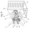
- Fig. 11 and FIG. 12 show the laying unit 23 in the acquisition of the adhesive tape 61 prepared by the tape station 26.
- Fig. 11 shows the depositing unit 23 together with parts of the belt station 26 from below, for the sake of clarity, only the upper winding gripper 22 is made visible, the lower winding gripper is in Fig. 11 not shown.
- the winding gripper 22 are not yet closed, the winding 2 is in Fig. 11 still held by the fingers 33,34 of the Wicklertellers 32.
- the drawn from the tape take-off gripper 72 from the tape supply 62 adhesive tape 61 is held by two each consisting of a rotatable roller arm 74 and a fixed pressure arm 75 roller grippers 76, wherein the tape take-off gripper 72 has already been opened.
- the roller grippers 76 are part of the binding device 27.
- the band gripper 69 When the band gripper 69 is closed, the adhesive tape 61 running in the y direction is severed by means of the knife 70 at the point 77 marked with dots.
- the cable storage-side end of the adhesive tape 61 is held by the band gripper 69.
- Fig. 12 Shown is the depositing unit 23 and the binding device 27 ready for the movement in the x direction to the tray 24 and on the way to the tray 24 for the production of the composite 4.
- the winding 2 has been taken over by the winding grippers 22 from the winder 17 and is of these recorded.
- the section of the adhesive tape 61 is held in place by means of the roller grippers 76 and is ready for the setting process.
- Fig. 13 and Fig. 14 show the Abbind worn 27 during Abbindvorgang.
- the winding grippers 22 have been shown not visible because of the better overview.
- the roller arm 74 of the roller gripper 76 can perform the rotational movement P8 and is rotatable by means of a pneumatic rotary unit 78.
- a roller 79 of the roller arm 74 presses the adhesive tape 61 against the pressure arm 75, wherein the non-adhesive side of the adhesive tape 61 on the pressure arm 75 and the adhesive layer of the adhesive tape 61 on the roller 79 is located.
- Reel grab 76 and rotary unit 78 are movable by means of a pneumatic linear unit 80 in the y-direction, wherein the two roller claws 76 are movable against each other or apart.
- the two pneumatic linear units 80 are in turn movable in the x-direction by means of a pneumatic, consisting of push rods 82 and cylinder 83 linear unit 81.
- a pneumatic linear unit 80 is in turn movable in the x-direction by means of a pneumatic, consisting of push rods 82 and cylinder 83 linear unit 81.
- the roller grippers 76 have been moved in the x-direction against the cable feed direction to the winder 17, the adhesive layer of the adhesive tape 61 coming to rest on the winding 2. Due to the relative movement of the roller gripper 76 relative to the winding 2, the in Fig.
Landscapes
- Wire Processing (AREA)
- Winding, Rewinding, Material Storage Devices (AREA)
- Winding Filamentary Materials (AREA)
- Basic Packing Technique (AREA)
Abstract
Description
- Die Erfindung betrifft einen Wickler und ein Verfahren zum Herstellen eines Wickels mit mindestens einer Windung, wobei ein an einem drehbaren Wicklerteller angeordneter Wicklergreifer das voreilende Kabelende eines Kabelabschnittes festhält und am Wicklerteller peripher angeordnete Finger den Kabelabschnitt zum Wickel formen gemäss der Definition der unabhängigen Patentansprüche.
- Die Offenlegungsschrift
DE 42 35 007 A1 offenbart eine Wickelvorrichtung für Kabelabschnitte, bei der die Innenwände einer Trommel als Anlageflächen für die Ausbildung des Wickels dienen und somit den Aussendurchmesser des Wickels vorgeben. Bei dieser Vorrichtung bleibt die Trommel während des Einschiebens des Kabels in Ruhe und wird nach Erreichen der Kabellänge und Abbinden des Wickels geöffnet. Nach der Übergabe der beiden Kabelenden des Wickels an Transfergreifer sind nachfolgende Kabelendbearbeitungen, beispielsweise Crimpen und/oder Tüllen aufsetzen, machbar. Nebst Vorteilen von wenig bewegten Massen sind auch Nachteile zu erwähnen, wie beispielsweise nicht kontrollierbare Biegeradien beim Einschieben und Zusammendrücken der verschiedenen Wickellagen zum Abbinden. Ob die einzelnen Wickel immer an der Wand anliegen ist ungewiss. Minimale Biegeradien beim Eintritt und Austritt des Kabels in bzw. aus der Trommel sind ebenfalls nicht gegeben. - Aus der Patentschrift
EP 1 387 449 B1 ist eine Wickelvorrichtung mit kontrollierbarem Minimalbiegeradius für Kabel, insbesondere Lichtwellenleiter bekannt geworden. Bei dieser Vorrichtung wird der Kabelabschnitt mittels einer Wickeleinheit zu einem Wickel gewickelt, wobei die Kabelenden nach Erreichen der richtigen Kabellänge identisch lang sind und die Kabelenden nach dem Abbinden des Wickels von Transfergreifern zur Weiterbearbeitung übernommen werden. Für Lichtwellenleiter ist der hohe Aufwand an Mechanik und Steuerung eher gerechtfertigt als für Kabel mit Kupferleiter. - Die Schrift
WO 03/018456 A1 - Die Handhabung langer Kabelabschnitte (ab beispielsweise 7 m Kabellänge) ist bei vielen Typen von Kabelbearbeitungsmaschinen schwierig. Bei Schwenkmaschinen mit Schwenkarmen muss die Kabelablage so lang wie der Kabelabschnitt sein. Bei Transfermaschinen mit auf einer Geraden verfahrbaren Transfereinheiten liegen beim Transport mehrere schlaufenförmige Kabel aufeinander, was bei einem schnellen Transport mittels der Transfereinheit relativ hohe Kabelzugkräfte bewirken kann, weil das Kabel nur an den Enden gehalten wird.
- In den oben genannten Schriften sind Lösungsansätze für Transfermaschinen aufgezeigt worden. Separate, der Kabelbearbeitungsmaschine nachgeschaltete Wickelvorrichtungen konnten sich nicht durchsetzen, weil mit den seriellen Bearbeitungsprozessen die Taktzeit bzw. die gesamte Bearbeitungszeit für einen aufgewickelten Kabelabschnitt entsprechend lang war.
- Hier will die Erfindung Abhilfe schaffen. Die Erfindung, wie sie in den Hauptansprüchen gekennzeichnet ist, löst die Aufgabe, eine Einrichtung und ein Verfahren zur Herstellung von langen Kabelabschnitten zu schaffen ohne die gesamte Bearbeitungszeit zu verlängern.
- Vorteilhafte Weiterbildungen der Erfindung sind in den abhängigen Patentansprüchen angegeben.
- Die erfindungsgemässe Einrichtung eignet sich besonders für Kabelbearbeitungsmaschinen mit Schwenkarmen. Die erfindungsgemässe Einrichtung kann aber auch bei Transfermaschinen mit linear verfahrbaren Transporteinheiten verwendet werden, falls zusätzliche Greifer und Übergabevorrichtungen für die Handhabung der Kabelenden und des Kabelwickels vorgesehen sind.
- Im nachfolgend gezeigten Ausführungsbeispiel einer Kabelbearbeitungsmaschine mit Schwenkarmen ist der Wickler zwischen einer Trenn-/Abisoliereinheit und einem zweiten Schwenkarm angeordnet. Die Aufwicklung des Kabelabschnittes erfolgt mittels eines Wickeltellers, der mittels geregeltem Motor in Abhängigkeit eines ebenfalls motorisch geregelten Bandantriebes drehbar ist, wobei der Bandantrieb dem Kabelvorschub und der Längenmessung des vorgeschobenen Kabels dient. Diese Anordnung ist besonders vorteilhaft für elastische Kabel. Das voreilende Kabelende des aufzuwickelnden Kabels wird mittels Bearbeitungsstationen bearbeitet und nach der Bearbeitung mittels eines ersten Schwenkarmes wieder zur Trenn-/Abisoliereinheit zurückgeschwenkt und mit dem Bandantrieb eine kurze Länge vorgeschoben, wobei der Wickler das voreilende Kabelende greifen kann. Dann schiebt der Bandantrieb das Kabel um die gewünschte Länge des Kabelabschnittes vor und der Wickler wickelt das vorgeschobene Kabel gleichzeitig zu einem Wickel. Nach dem Wickelvorgang ergreift eine linear verfahrbare Ablegeinheit den Wickel. Dabei entspannt der Wicklerteller seine Spannfinger pneumatisch und fährt pneumatisch nach hinten. Formbleche wirken als Abstreifer verhindern das Mitziehen des Wickels nach hinten. Dann bewegt sich die Ablegeinheit mit dem Wickel zurück, damit das nacheilende Kabelende getrennt und abisoliert und falls nötig bearbeitet werden kann, wobei ein zweiter Schwenkarm das nacheilende Kabelende Bearbeitungsstationen zuführt. Greifer der Ablegeinheit halten den Wickel und die Ablegeinheit bewegt sich bis etwa unter den Drehpunkt des zweiten Schwenkarmes und das nacheilende Kabelende kann, falls nötig, für die Bearbeitung seines Endes mittels des zweiten Schwenkarmes noch aus dem Wickel ausgezogen werden. Nach der Bearbeitung des nacheilenden Kabelendes bewegt sich die Ablegeinheit weiter in Kabelvorschubrichtung zur Ablage. Während der Bearbeitung des nacheilenden Kabelendes und auf der Fahrt zur Ablage kann der Wickel mit einem Abbund versehen werden. Der Wickel kann während der Bearbeitung des nacheilenden Kabelendes oder während der Bearbeitung des voreilenden Kabelendes des nächsten Kabelabschnittes mit dem Abbund versehen werden. Der abgebundene Wickel kann danach in Behälter, auf Transportbänder oder sonstige Aufnahmemittel, beispielsweise Dorne abgegeben werden.
- Die durch die Erfindung erreichten Vorteile sind im wesentlichen darin zu sehen, dass der Abbindvorgang am Wickel zeitlich parallel zum Bearbeitungsvorgang am Kabelabschnitt erfolgt. Damit wird die gesamte Bearbeitungzeit für den Kabelabschnitt, auch Maschinenzykluszeit genannt, nicht verlängert. Die gesamte Bearbeitungszeit bleibt dieselbe mit oder ohne Abbund. Die Zeit für die Herstellung des Wickels ist vergleichbar mit der Zeit für die Ablage eines gestreckten Kabelabschnittes bei einer herkömmlichen Kabelbearbeitungsmaschine.
- Mechanisch ist der Wickler und die Ablegeinheit nicht als separate Einrichtung zur Kabelbearbeitungsmaschine geschaltet, sondern bildet eine integrale Einheit der Kabelbearbeitungsmaschine. Der herzustellende und zu bearbeitende Kabelabschnitt wird ab dem Kabelvorrat abgelängt, am voreilenden Kabelende bearbeitet, aufgewickelt, allenfalls am nacheilenden Kabelende bearbeitet und als Wickel mit Abbund der Ablage übergeben ohne dass ein manueller Eingriff notwendig ist.
- Weiter vorteilhaft ist, dass die Kabelbearbeitungsmaschine trotz langer Kabelabschnitte gegenüber einer herkömmlichen Kabelbearbeitungsmaschine kurz baut. Die Länge der Kabelbearbeitungsmaschine wird nicht durch die Länge des Kabelabschnittes bestimmt.
- Bei der erfindungsgemässen Kabelbearbeitungsmaschine und dem erfindungsgemässen Verfahren zur Herstellung und Bearbeitung eines Kabelabschnittes wird der Kabelabschnitt ab einem Kabelvorrat abgelängt und an den Kabelenden bearbeitet, wobei ein Wickler vorgesehen ist, der den Kabelabschnitt zu einem Wickel mit mindestens einer Windung formt und eine Ablegeinheit mit einer Abbindeinrichtung den Wickel mit einem Abbund versieht.
- Anhand der beiliegenden Figuren wird die vorliegende Erfindung näher erläutert.
- Es zeigen:
-
Fig. 1
einen zu einem Wickel geformten Kabelabschnitt, -
Fig. 2
eine Kabelbearbeitungsmaschine im Grundriss, -
Fig. 3
eine Kabelbearbeitungsmaschine in dreidimensionaler Darstellung, -
Fig. 4
einen Wickler, der den Kabelabschnitt zu einem Wickel formt, -
Fig. 5
den Wickler von der Rückseite her gesehen, -
Fig. 6
Linearführungen eines Wicklertellers, -
Fig. 7
Einzelheiten des Wicklers, -
Fig. 8 bis Fig. 10
eine Bandstation zur Vorbereitung eines Klebbandes, -
Fig. 11 undFig 12
eine Ablegeinheit bei der Übernahme des Klebbandes, -
Fig. 13 undFig. 14
eine Abbindeinrichtung beim Abbindvorgang. -
Fig. 1 zeigt einen Kabelabschnitt 1, der mit mehreren Windungen 3 zu einem Wickel 2 geformt ist, wobei die Windungen 3 mittels eines Abbundes 4 zusammengehalten werden. Der Abbund 4 kann beispielsweise aus einem Band mit einseitig aufgetragenem Kleber bestehen, wobei die Kleberseite des Bandes die Windungen 3 umfasst und die Bandenden kleberseitig aufeinander liegen. Das voreilende Kabelende 5 ist bearbeitet, beispielsweise ist ein Crimpkontakt 6 allenfalls mit einer Dichtungstülle angeschlagen. Das voreilende Kabelende 5 kann auch nur abisoliert oder gar nicht bearbeitet sein. Das nacheilende Kabelende 7 ist bearbeitet, beispielsweise ist ein Crimpkontakt 8 allenfalls mit einer Dichtungstülle angeschlagen. Das nacheilende Kabelende 7 kann auch nur abisoliert oder gar nicht bearbeitet sein. -
Fig. 2 zeigt eine Kabelbearbeitungsmaschine 10 im Grundriss undFig. 3 die Kabelbearbeitungsmaschine 10 in dreidimensionaler Darstellung. - Am Eingang der Kabelbearbeitungsmaschine 10 ist eine Kabelvorschubeinrichtung vorgesehen, bestehend aus einem Bandantrieb 11 und aus einer Längenmessvorrichtung 12. Der Bandantrieb 11 führt ein Kabel 13 einem ersten Schwenkarm 14 mit einem ersten Greifer 15 zu. Der Bandantrieb 11 schiebt das Kabel 13 vor und die Längenmessvorrichtung 12 misst die vorgeschobene Kabellänge, wobei die vorgeschobene Kabellänge dem herzustellenden und an den Enden zu bearbeitenden Kabelabschnitt entspricht. Nicht dargestellt ist der Kabelvorrat, beispielsweise ein Kabelfass oder eine Kabelspule.
- Mittels Antrieben kann der erste Schwenkarm 14 in eine mit einem Pfeil P1 symbolisierte Schwenkbewegung und/oder in eine mit einem Pfeil P2 symbolisierte Linearbewegung versetzt werden. Der erste Schwenkarm 14 bedient als Zuführeinrichtung mittels Drehbewegung P1 und Linearbewegung P2 seitlich der Kabellängsachse KL angeordnete Bearbeitungsstationen 16 (beispielsweise Crimppressen und/oder Tüllenbestücker) mit voreilenden Kabelenden 5.
- Nach der Bearbeitung des voreilenden Kabelendes 5 bringt der erste Schwenkarm 14 mittels Greifer 15 das voreilende Kabelende 5 wieder zurück in die Kabellängsachse KL. Dann wird das Kabel 13 mittels Bandantrieb 11 vorgeschoben bis ein Wickler 17 das voreilende Kabelende 5 greifen kann. Danach schiebt der Bandantrieb 11 der vorgegebene und mittels der Längenmessvorrichtung 12 gemessene Kabelabschnitt 1 vor und der mit dem Bandantrieb 11 synchronisierte Wickler 17 wickelt den vorgeschobenen Kabelabschnitt gleichzeitig zu einem Wickel 2 gemäss
Fig. 1 auf. Nach der Herstellung des Wickels 2 wird der Kabelabschnitt 1 vom Kabel 13 mittels einer Trenn-/Abisoliereinheit mit Trenn-/Abisoliermessern 18 getrennt und/oder abisoliert. Das voreilende Kabelende des nächsten Kabelabschnittes wird vom ersten Schwenkarm 14 mittels Greifer 15 gefasst und zur Bearbeitung den Bearbeitungsstationen 16 zugeführt. - Das nacheilende Kabelende 7 des aufgewickelten Kabelabschnittes 1 wird von einem zweiten Schwenkarm 19 mittels zweitem Greifer 20 gefasst und in eine mit einem Pfeil P3 symbolisierte Schwenkbewegung und/oder in eine mit einem Pfeil P4 symbolisierte Linearbewegung versetzt, wobei das nacheilende Kabelende 7 seitlich der Kabellängsachse KL angeordneten Bearbeitungsstationen 21 (beispielsweise Crimppressen und/oder Tüllenbestücker) zugeführt wird.
- Vor der Bearbeitung des nacheilenden Kabelendes 7 wird der Wickel 2 von Wickelgreifern 22 einer Ablegeinheit 23 übernommen. Danach bewegt sich die Ablegeinheit 23 in Kabelvorschubrichtung in Richtung zu einer Ablage 24 bis die Ablegeinheit 23 etwa unterhalb des Schwenkarmantriebes 25 des zweiten Schwenkarmes 19 zu stehen kommt.
- Vor der Bearbeitung des nacheilenden Kabelendes 7 stellt eine Bandstation 26 einen Bandabschnitt für die Herstellung des Abbundes 4 bereit. Der Bandabschnitt wird von einer Abbindeinrichtung 27 der Ablegeinheit 23 übernommen.
- Nach der Bearbeitung des nacheilenden Kabelendes 7 bringt der zweite Schwenkarm 19 mittels Greifer 20 das nacheilende Kabelende 7 wieder etwa in die Kabellängsachse KL zurück und die Ablegeinheit 23 wird mit dem Wickel 2 weiter in Richtung Ablage 24 bewegt. Auf der Fahrt der Ablegeinheit 23 zur Ablage 24 wird der Abbund 4 mittels der Abbindeinrichtung 27 hergestellt. Der Wickel 2 mit Abbund 4 wird nach Gut-/Schlechtkriterien sortiert in den einen oder anderen Behälter 31 der Ablage 24 gelegt. Ein Riemenantrieb 28 bewegt die Ablegeinheit 23 mittels Riemen 85 entlang einer an einem Maschinengestell 30 angeordneten Linearführung 29.
- In
Fig. 3 sind die Richtungspfeile x, y und z eingetragen. Das Kabel 13 wird mittels des Bandantriebes 11 in x-Richtung vorgeschoben, bzw. die Kabellängsachse KL liegt in der x-Richtung. Die Ablegeinheit 23 bewegt sich in der x-Richtung und legt den fertigen Wickel 2 in z-Richtung in den entsprechenden Behälter 31. Der Wickler 17 ist zur Abstreifung des Wickels 2 wie inFig. 6 gezeigt in y-Richtung bewegbar. -
Fig. 4 zeigt den Wickler 17, der den Kabelabschnitt 1 zu einem Wickel 2 formt. An einem drehbaren Wicklerteller 32 sind Stützfinger 33 und Spannfinger 34 kreisrund, peripher angeordnet. Stützfinger 33 und Spannfinger 34 tragen die Windungen 3 des Wickels 2.Fig. 7 zeigt Einzelheiten der Finger 33,34. Der Wicklerteller 32 liegt in der durch die Achsen x und z aufgespannten Ebene und dreht sich um eine horizontal verlaufende Drehachse 86, die parallel zur y-Achse verläuft. Nach der Bearbeitung des voreilenden Kabelendes 5 schiebt der Bandantrieb 11 das Kabel 13 weiter vor. Sobald das voreilende Kabelende 5 eine erste Rolle 35 einer Kabelführung 38 passiert, wird die Rolle 35 und ein Gegenfinger 42 mittels einer Antriebseinheit 43 in eine Linearbewegung P6 und der Gegenfinger 42 zusätzlich in eine Drehbewegung P7 versetzt. Gleichzeitig versetzt die Rolle 35 einen Leitfinger 36 in eine Drehbewegung P5 um eine feststehende Achse 48, wobei sich der Leitfinger 36 zum Gegenfinger 42 bewegt und das Kabel 13 beim Vorschieben in Richtung eines geöffneten Wicklergreifers 37 ablenkt. Leitfinger 36 und Gegenfinger 42 dienen auch als Führungshilfe zur seitlichen Führung des Kabels 13. Der Wicklergreifer 37 ist innerhalb des durch die Finger 33,34 gebildeten Kreises am Wicklerteller 32 angeordnet. Rolle 35, Leitfinger 36, Gegenfinger 42 und die die Linearbewegung P6 erzeugende Antriebseinheit 43 bilden die gegenüber dem Wicklerteller 32 feststehende Kabelführung 38. Die Längenmessvorrichtung 12 misst die vorgeschobene Kabellänge und die Steuerung stoppt den Bandantrieb 11 sobald die bis zum Wicklergreifer 37 notwendige Kabellänge erreicht ist. Dann wird der das Kabelende umgreifende Wicklergreifer 37 geschlossen. Ein Wicklerantrieb 39 treibt den Wicklerteller 32 an, wobei der Wicklerantrieb 39 und der Bandantrieb 11 beim Herstellen des Wickels 2 synchronisiert sind, was der Bandantrieb 11 an Kabel vorschiebt, wird vom Wicklerteller 32 gleichzeitig aufgewickelt, wobei die Windungen 3 des entstehenden Wickels 2 auf den Fingern 33,34 aufliegen. Nach dem Wickelvorgang wird der Wickel 2 von den Wickelgreifern 22 der Ablegeinheit 23 gefasst und der Wicklerteller 32 in y-Richtung mittels eines Zylinders 41 bewegt, wobei ein zwischen die Finger 33,34 greifender, gegenüber dem Wicklerteller 32 fest angeordneter Abstreifer 40 den Wickel 2 ab den Fingern 33,34 schiebt. Einzelheiten dazu sind inFig. 6 undFig. 7 gezeigt. -
Fig. 5 zeigt die Rückseite des Wicklers 17 undFig. 6 die Vorderseite des Wicklertellers 32 mit Linearführungen 47. Ein Motorpulley des Wicklerantriebes 39 treibt einen Zahnriemen 45 an, der ein Wicklerpulley 46 und somit den Wicklerteller 32 antreibt. Der Wicklerteller 32 ist mitsamt des Wicklerantriebs 39 entlang von Linearführungen 47 in y-Richtung mittels Zylinder 41 zum Zweck der Abstreifung des Wickels 2 von den Fingern 33,34 bewegbar, wobei der Wickel 2 am feststehenden Abstreifer 40 ansteht und so über die Finger 33,34 geschoben wird. Mit 49 ist ein Luftanschluss bezeichnet, über den Druckluft zu pneumatischen Einheiten (Wicklergreifer 37, Spannfinger 34) des Wicklertellers 32 zuführbar ist. Das Motorpulley 44 ist mittels einer Kupplung 50 mit dem Wicklerantrieb 39 verbunden. -
Fig. 7 zeigt Einzelheiten des Wicklers 17 insbesondere die am Wicklerteller 32 angeordneten pneumatischen Einheiten wie Wicklergreifer 37 und Spannfinger 34. Die Stützfinger 33 tragen die Windungen 3 des Wickels 2. Die Spannfinger 34 tragen und halten die Windungen 3 des Wickels 2. Jeder Spannfinger 34 weist am freien Ende eine Nase 51 auf, die den Wickel 2 während des Wickelvorganges zurückhalten. Zudem ist der Spannfinger 34 mittels eines pneumatischen Antriebs 52 um eine Achse 53 drehbar. In der gezeigten Lage kann der Wickel 2 von den Fingern 33,34 mittels Abstreifer 40 abgestreift werden. Der pneumatische Antrieb 52 betätigt mittels Zylinder 54 einen um eine Achse 73 drehbaren Hebel 55, der den Spannfinger 34 mittels in Langlöcher 56 eingreifende Bolzen 57 um die Achse 53 dreht bis der Spannfinger 34 dieselbe Lage hat wie die Stützfinger 33. In dieser Lage ist der Wicklerteller 32 bereit für den Wickelvorgang. -
Fig. 7 zeigt den Wicklergreifer 37 zum Festhalten des voreilenden Kabelendes 5. Die beiden in geschlossener Lage gezeigten Greiferhälften 58 sind pneumatisch um eine Achse 59 drehbar bzw. öffenbar und umgreifen mittels Fingern 60 das Kabelende. -
Fig. 8 bis Fig. 10 zeigen eine Bandstation 26 bei der ein Klebband 61 mit einseitig aufgetragener Kleberschicht auf eine für den Abbund 4 notwendige Länge vorbereitet wird. Ein Bandvorrat 62 liegt auf einem in z-Richtung mittels Zylinder 63 höhenverstellbaren Bandteller 64, der zum erstmaligen, manuellen Einfädeln des Klebbandes 61 der besseren Zugänglichkeit wegen in der oberen Lage ist. Am Bandteller 64 ist ein Finger 65 mit zwei Fingerbolzen 66 angeordnet. Das Klebband 61 wird auf der kleberlosen bzw. trockenen Seite manuell über den tellernahen Fingerbolzen 66 abgezogen und der Bandanfang auf der Seite mit der Kleberschicht am tellerfernen Fingerbolzen 66 festgeklebt. Das manuelle Einfädeln ist damit beendet und der Bandteller 64 wird abgesenkt und mittels Zylinder 67 geschwenkt bis das Klebband 61 wie inFig. 9 gezeigt in Linie ist mit einem ausfahrbaren Umlenkbolzen 68 und einem Bandgreifer 69 mit Messer 70. Danach wird der Bandgreifer 69 geschlossen und das Klebband 61 mittels Messer 70 durchtrennt. Wie inFig. 10 gezeigt wird der Bandteller 64 in die Ausgangslage zurückgeschwenkt. Der am tellerfernen Fingerbolzen 66 klebende Bandrest wird manuell entfernt. Ein mittels pneumatischer Lineareinheit 71 linear in y-Richtung betätigbarer Bandabzuggreifer 72 wird dann geöffnet zwischen Umlenkbolzen 68 und Bandgreifer 69 verfahren. Anschliessend wird der Bandabzuggreifer 72 geschlossen und der Bandgreifer 69 geöffnet. Die Lineareinheit 71 bewegt nun den Bandabzuggreifer 72 zurück und mit ihm wird das Klebband 61 ab dem Bandvorrat 62 um die Länge mitgezogen wie sie für die Herstellung des Abbundes 4 notwendig ist. - Anstelle des Klebbandes 61 kann ein Band mit vergleichbaren Eigenschaften verwendet werden. Beispielsweise eignet sich auch ein Kunststoffband mit einseitig, wellenförmig angeordneten Halbkugelköpfen auf kurzem Stamm, die durch Zusammendrücken gegenseitig eine feste aber lösbare Verbindung entstehen lassen.
-
Fig. 11 undFig 12 zeigen die Ablegeinheit 23 bei der Übernahme des von der Bandstation 26 vorbereiteten Klebbandes 61.Fig. 11 zeigt die Ablegeinheit 23 zusammen mit Teilen der Bandstation 26 von unten, wobei der besseren Übersicht wegen lediglich der obere Wickelgreifer 22 sichtbar gemacht ist, der untere Wickelgreifer ist inFig. 11 nicht dargestellt. Die Wickelgreifer 22 sind noch nicht geschlossen, der Wickel 2 wird inFig. 11 noch von den Fingern 33,34 des Wicklertellers 32 festgehalten. Das vom Bandabzuggreifer 72 ab dem Bandvorrat 62 ausgezogene Klebband 61 wird von zwei aus je einem drehbaren Rollenarm 74 und einem feststehenden Druckarm 75 bestehenden Rollengreifern 76 festgehalten, wobei der Bandabzuggreifer 72 bereits geöffnet worden ist. Die Rollengreifer 76 sind Teil der Abbindeinrichtung 27. Beim Schliessen des Bandgreifers 69 wird das in y-Richtung verlaufende Klebband 61 mittels des Messers 70 an der mit Punkten markierten Stelle 77 durchtrennt. Das kabelvorratseitige Ende des Klebbandes 61 wird vom Bandgreifer 69 festgehalten. Wie inFig. 12 gezeigt ist die Ablegeinheit 23 und die Abbindeinrichtung 27 bereit für die Bewegung in x-Richtung zur Ablage 24 und auf dem Weg zur Ablage 24 zur Herstellung des Abbundes 4. Der Wickel 2 ist von den Wickelgreifern 22 vom Wickler 17 übernommen worden und wird von diesen festgehalten. Der Abschnitt des Klebbandes 61 wird mittels der Rollengreifer 76 festgehalten und ist bereit für den Abbindvorgang. -
Fig. 13 undFig. 14 zeigen die Abbindeinrichtung 27 beim Abbindvorgang. Die Wickelgreifer 22 sind der besseren Übersicht wegen nicht sichtbar gezeigt worden. Der Rollenarm 74 des Rollengreifers 76 kann die Drehbewegung P8 ausführen und ist mittels einer pneumatischen Dreheinheit 78 drehbar. Eine Rolle 79 des Rollenarmes 74 presst das Klebband 61 gegen den Druckarm 75, wobei die kleberlose Seite des Klebbandes 61 auf dem Druckarm 75 und die Kleberschicht des Klebbandes 61 auf der Rolle 79 liegt. Rollengreifer 76 und Dreheinheit 78 sind mittels einer pneumatischen Lineareinheit 80 in y-Richtung bewegbar, wobei die beiden Rollengreifer 76 gegeneinander oder auseinander bewegbar sind. Die beiden pneumatischen Lineareinheiten 80 sind wiederum in x-Richtung mittels einer pneumatischen, aus Schubstangen 82 und Zylinder 83 bestehende Lineareinheit 81 bewegbar. Wie inFig. 13 gezeigt sind die Rollengreifer 76 in x-Richtung entgegen der Kabelvorschubrichtung zum Wickler 17 bewegt worden, wobei die Kleberschicht des Klebbandes 61 auf den Wickel 2 zu liegen kommt. Durch die Relativbewegung der Rollengreifer 76 gegenüber dem Wickel 2 werden die inFig. 11 gezeigten, freien Ende 84 des Klebbandes 61 über die Rollen 79 gezogen ohne diese zu verlassen. In der inFig. 13 gezeigten Endlage der Rollengreifer 76 ist das Klebband 61 bereit für die Herstellung des Abbundes 4. Zur Herstellung des Abbundes 4 werden die beiden Rollengreifer 76 in y-Richtung gegeneinander bewegt, wobei die Druckarme 75 das Klebband 61 um den Wickel 2 legen und die beiden übrigbleibenden Bandenden Kleberschicht auf Kleberschicht aufeinander drücken, dabei verlassen die Enden 84 die Rollen 79. Anschliessend schiebt die Lineareinheit 81 die Lineareinheit 80 und mit ihr die Rollengreifer 76 in die inFig. 14 gezeigte Endlage in x-Richtung. Der Wickel 2 mit dem Abbund 4 ist nun bereit für die Übergabe an die Ablage 24 in einen der Behälter 31. Die Übergabe erfolgt durch Öffnen der Wickelgreifer 22.
Claims (10)
- Wickler (17) zum Herstellen eines Wickels (2) mit mindestens einer Windung (3), wobei ein an einem drehbaren Wicklerteller (32) angeordneter Wicklergreifer (37) das voreilende Kabelende (5) eines Kabelabschnittes (1) festhält und am Wicklerteller (32) peripher angeordnete Finger (33,34) den Kabelabschnitt (1) zum Wickel (2) formen,
dadurch gekennzeichnet,
dass der Wicklerteller (32) um eine horizontale Drehachse (86) drehbar ist und dass der Wicklergreifer (37) innerhalb der Finger (33,34) am Wicklerteller (32) angeordnet ist und eine Kabelführung (38) das voreilende Kabelende (1) dem Wicklergreifer (37) zuführt. - Wickler nach Anspruch 1,
dadurch gekennzeichnet,
dass der Wicklerteller (32) zum Zweck der Abstreifung des Wickels (2) von den Fingern (33,34) in Richtung der horizontalen Drehachse (86) bewegbar ist, wobei der Wickel (2) an einem feststehenden Abstreifer (40) ansteht und so über die Finger (33,34) schiebbar ist. - Wickler nach einem der Ansprüche 1 oder 2,
dadurch gekennzeichnet,
dass der Wicklerteller (32) mitsamt eines Wicklerantriebs (39) entlang von Linearführungen (47) in Richtung der horizontalen Drehachse (86) bewegbar ist. - Wickler nach Anspruch 3,
dadurch gekennzeichnet,
dass der Wicklerteller (32) mittels Motorpulley (44), Riemen (45) und Wicklerpulley (46) antreibbar ist. - Wickler nach einem der vorhergehenden Ansprüche,
dadurch gekennzeichnet,
dass die die Windungen (3) des Wickels (2) tragenden Stützfinger (33) und Spannfinger (34) an der Peripherie des Wicklertellers (32) kreisrund angeordnet sind. - Wickler nach Anspruch 5,
dadurch gekennzeichnet,
dass je Spannfinger (34) am freien Ende eine Nase (51) vorgesehen ist, die den Wickel (2) während des Wickelvorganges zurückhält und
dass der Spannfinger (34) um eine Achse (53) in Richtung der horizontalen Drehachse (86) schwenkbar ist, wobei die Nase (51) den Wickel (2) zum Abstreifen freigibt. - Wickler nach einem der vorhergehenden Ansprüche,
dadurch gekennzeichnet,
dass die Kabelführung (38) eine Rolle (35), einen Leitfinger (36) und einen Gegenfinger (42) aufweist, wobei die Rolle (35) und der Gegenfinger (42) in eine Linearbewegung (P6) und der Gegenfinger (42) zusätzlich in eine Drehbewegung (P7) versetzbar sind und der Leitfinger (36) mittels der Rolle (35) in eine Drehbewegung (P5) versetzbar ist, wobei das voreilende Kabelende (5) beim Vorschieben in Richtung Wicklergreifer (37) ablenkbar ist. - Verfahren zum Herstellen eines Wickels (2) mit mindestens einer Windung (3), wobei das voreilende Kabelende (5) eines Kabelabschnittes (1) mittels eines an einem drehbaren Wicklerteller (32) angeordneten Wicklergreifers (37) festgehalten wird und der Kabelabschnitt (1) mittels am Wicklerteller (32) peripher angeordneten Fingern (33,34) zum Wickel (2) geformt wird,
dadurch gekennzeichnet,
dass der Wicklerteller (32) um eine horizontale Drehachse (86) gedreht wird und das voreilende Kabelende (5) innerhalb der Finger (33,34) mittels Wicklergreifer (37) am Wicklerteller (32) festgehalten wird, wobei das voreilende Kabelende (1) mittels einer Kabelführung (38) dem Wicklergreifer (37) zugeführt wird. - Verfahren nach Anspruch 8,
dadurch gekennzeichnet,
dass der Wickel (2) mittels an der Peripherie des Wicklertellers (32) kreisrund angeordneten Stützfingern (33) und Spannfingern (34) getragen wird. - Verfahren nach einem der Ansprüche 8 oder 9,
dadurch gekennzeichnet,
dass der Wicklerteller (32) zum Zweck der Abstreifung des Wickels (2) von den Fingern (33,34) in Richtung der horizontalen Drehachse (86) bewegt wird, wobei der Wickel (2) an einem feststehenden Abstreifer (40) ansteht und so über die Finger (33,34) geschoben wird.
Priority Applications (1)
| Application Number | Priority Date | Filing Date | Title |
|---|---|---|---|
| EP08155332A EP1988044B1 (de) | 2007-05-04 | 2008-04-29 | Wickler und Verfahren zum Herstellen eines Wickels |
Applications Claiming Priority (2)
| Application Number | Priority Date | Filing Date | Title |
|---|---|---|---|
| EP07107578 | 2007-05-04 | ||
| EP08155332A EP1988044B1 (de) | 2007-05-04 | 2008-04-29 | Wickler und Verfahren zum Herstellen eines Wickels |
Publications (2)
| Publication Number | Publication Date |
|---|---|
| EP1988044A1 true EP1988044A1 (de) | 2008-11-05 |
| EP1988044B1 EP1988044B1 (de) | 2012-09-19 |
Family
ID=38543667
Family Applications (1)
| Application Number | Title | Priority Date | Filing Date |
|---|---|---|---|
| EP08155332A Active EP1988044B1 (de) | 2007-05-04 | 2008-04-29 | Wickler und Verfahren zum Herstellen eines Wickels |
Country Status (3)
| Country | Link |
|---|---|
| US (1) | US8052079B2 (de) |
| EP (1) | EP1988044B1 (de) |
| MX (1) | MX2008005731A (de) |
Cited By (4)
| Publication number | Priority date | Publication date | Assignee | Title |
|---|---|---|---|---|
| ITVR20130161A1 (it) * | 2013-07-15 | 2015-01-16 | Cosymo Ltd | Apparecchiatura avvolgitrice per formare una matassa di filo o corda |
| CN108216795A (zh) * | 2018-03-23 | 2018-06-29 | 东莞市新标自动化设备有限公司 | 卷绕定型装置 |
| CN111483880A (zh) * | 2020-04-29 | 2020-08-04 | 深圳市联合东创科技有限公司 | 线缆缠绕设备 |
| CN115571724A (zh) * | 2022-09-19 | 2023-01-06 | 贵州电网有限责任公司 | 一种用于配网导线发放器的线缆分段转存装置 |
Families Citing this family (1)
| Publication number | Priority date | Publication date | Assignee | Title |
|---|---|---|---|---|
| WO2014043387A1 (en) * | 2012-09-12 | 2014-03-20 | Windak Inc. | System and method for coiling and sealing an elongate flexible component |
Citations (11)
| Publication number | Priority date | Publication date | Assignee | Title |
|---|---|---|---|---|
| US2624771A (en) * | 1948-04-30 | 1953-01-06 | Western Electric Co | Collapsible coiling head for electrically contacting insulated cable |
| DE3047887A1 (de) * | 1980-12-19 | 1982-07-22 | Reifenhäuser KG, 5210 Troisdorf | "vollautomatische wickel- und abbindemaschine, sowie ein wickelbundherstellverfahren fuer bunde aus rohren, schlaeuchen, kabeln, profilen usw." |
| JPS57131678A (en) | 1981-02-09 | 1982-08-14 | Nanmoto Kk | Winder for string formed body |
| US4390137A (en) * | 1981-04-28 | 1983-06-28 | Western Electric Company, Inc. | Forming a strand package having multiple coil lengths |
| JPS58112912A (ja) * | 1981-12-15 | 1983-07-05 | 株式会社浅羽製作所 | 自動巻取結束装置 |
| DE4235007A1 (de) | 1992-10-16 | 1994-04-21 | Fraunhofer Ges Forschung | Verfahren zum Wickeln und Vorrichtung zur Durchführung des Verfahrens |
| US5427327A (en) | 1993-09-27 | 1995-06-27 | At&T Corp. | Method and apparatus for capturing and positioning a cable |
| US5570853A (en) * | 1995-09-14 | 1996-11-05 | U Gear Automatic Machinery Co., Ltd. | Releasable cable holder assembly for winding machines |
| WO2003018456A1 (de) | 2001-08-29 | 2003-03-06 | Schleuniger Holding Ag | Spuler für draht- oder bandförmige meterware |
| EP1387449A1 (de) * | 2002-07-22 | 2004-02-04 | komax Holding AG | Vorrichtung und Verfahren zum Wickeln von kabelförmigem Material |
| EP1452474A1 (de) * | 2003-02-27 | 2004-09-01 | Bernhard Schäfer Werkzeug- und Sondermaschinen GmbH | Verfahren und Vorrichtung zur maschinellen Herstellung von spulenlosen Kabelwickeln |
Family Cites Families (1)
| Publication number | Priority date | Publication date | Assignee | Title |
|---|---|---|---|---|
| US353047A (en) * | 1886-11-23 | Wire-rod-reeling machine |
-
2008
- 2008-04-29 EP EP08155332A patent/EP1988044B1/de active Active
- 2008-05-02 MX MX2008005731A patent/MX2008005731A/es not_active Application Discontinuation
- 2008-05-02 US US12/114,136 patent/US8052079B2/en not_active Expired - Fee Related
Patent Citations (12)
| Publication number | Priority date | Publication date | Assignee | Title |
|---|---|---|---|---|
| US2624771A (en) * | 1948-04-30 | 1953-01-06 | Western Electric Co | Collapsible coiling head for electrically contacting insulated cable |
| DE3047887A1 (de) * | 1980-12-19 | 1982-07-22 | Reifenhäuser KG, 5210 Troisdorf | "vollautomatische wickel- und abbindemaschine, sowie ein wickelbundherstellverfahren fuer bunde aus rohren, schlaeuchen, kabeln, profilen usw." |
| JPS57131678A (en) | 1981-02-09 | 1982-08-14 | Nanmoto Kk | Winder for string formed body |
| US4390137A (en) * | 1981-04-28 | 1983-06-28 | Western Electric Company, Inc. | Forming a strand package having multiple coil lengths |
| JPS58112912A (ja) * | 1981-12-15 | 1983-07-05 | 株式会社浅羽製作所 | 自動巻取結束装置 |
| DE4235007A1 (de) | 1992-10-16 | 1994-04-21 | Fraunhofer Ges Forschung | Verfahren zum Wickeln und Vorrichtung zur Durchführung des Verfahrens |
| US5427327A (en) | 1993-09-27 | 1995-06-27 | At&T Corp. | Method and apparatus for capturing and positioning a cable |
| US5570853A (en) * | 1995-09-14 | 1996-11-05 | U Gear Automatic Machinery Co., Ltd. | Releasable cable holder assembly for winding machines |
| WO2003018456A1 (de) | 2001-08-29 | 2003-03-06 | Schleuniger Holding Ag | Spuler für draht- oder bandförmige meterware |
| EP1387449A1 (de) * | 2002-07-22 | 2004-02-04 | komax Holding AG | Vorrichtung und Verfahren zum Wickeln von kabelförmigem Material |
| EP1387449B1 (de) | 2002-07-22 | 2005-04-27 | komax Holding AG | Vorrichtung und Verfahren zum Wickeln von kabelförmigem Material |
| EP1452474A1 (de) * | 2003-02-27 | 2004-09-01 | Bernhard Schäfer Werkzeug- und Sondermaschinen GmbH | Verfahren und Vorrichtung zur maschinellen Herstellung von spulenlosen Kabelwickeln |
Cited By (7)
| Publication number | Priority date | Publication date | Assignee | Title |
|---|---|---|---|---|
| ITVR20130161A1 (it) * | 2013-07-15 | 2015-01-16 | Cosymo Ltd | Apparecchiatura avvolgitrice per formare una matassa di filo o corda |
| CN108216795A (zh) * | 2018-03-23 | 2018-06-29 | 东莞市新标自动化设备有限公司 | 卷绕定型装置 |
| CN108216795B (zh) * | 2018-03-23 | 2024-03-26 | 东莞创事达自动化科技有限公司 | 卷绕定型装置 |
| CN111483880A (zh) * | 2020-04-29 | 2020-08-04 | 深圳市联合东创科技有限公司 | 线缆缠绕设备 |
| CN111483880B (zh) * | 2020-04-29 | 2022-03-29 | 深圳市联合东创科技有限公司 | 线缆缠绕设备 |
| CN115571724A (zh) * | 2022-09-19 | 2023-01-06 | 贵州电网有限责任公司 | 一种用于配网导线发放器的线缆分段转存装置 |
| CN115571724B (zh) * | 2022-09-19 | 2024-05-28 | 贵州电网有限责任公司 | 一种用于配网导线发放器的线缆分段转存装置 |
Also Published As
| Publication number | Publication date |
|---|---|
| MX2008005731A (es) | 2009-03-02 |
| EP1988044B1 (de) | 2012-09-19 |
| US20090039194A1 (en) | 2009-02-12 |
| US8052079B2 (en) | 2011-11-08 |
Similar Documents
| Publication | Publication Date | Title |
|---|---|---|
| EP1988045B1 (de) | Kabelbearbeitungsmaschine und Verfahren zur Herstellung und Bearbeitung eines Kabelabschnittes | |
| DE2209435B2 (de) | Vorrichtung zum automatischen Aufrollen von Gewebebahnen bestimmter Länge | |
| EP2565992B1 (de) | Einrichtung und Verfahren zur Zubringung von Kabelenden zu Konfektioniereinheiten | |
| EP1988044B1 (de) | Wickler und Verfahren zum Herstellen eines Wickels | |
| EP3735737B1 (de) | Verfahren und vorrichtung zur herstellung von rotoren und statoren einschliesslich der konfektionierung von anschlussdrähten | |
| EP3736927A1 (de) | Ablängstation sowie verfahren zum automatischen ablängen von leitungselementen | |
| EP1452474B1 (de) | Verfahren und Vorrichtung zur maschinellen Herstellung von spulenlosen Kabelwickeln | |
| DE102011015060A1 (de) | Vorrichtung und Verfahren zum Herstellen von Rundbürsten | |
| DE3743948A1 (de) | Abziehfahrzeug fuer eine falschzwirnmaschine | |
| DE69201973T2 (de) | Maschine zum Scheren des vorderen Endes und zur Entnahme von Probenstücken von einem auf eine Wickelrolle gewickelten Band. | |
| DE202007013417U1 (de) | Vorrichtung zur Herstellung langer, konfektionierter, elektrischer Leitungen in einem CrimpCenter | |
| DE102016109155B3 (de) | Verdrillanlage, Tandem-Verdrillanlage und Verfahren zum Bestücken eines Verdrillkopfs | |
| EP1987897B1 (de) | Einrichtung und Verfahren zur Übernahme eines zu einem Wickel geformten Kabelabschnittes | |
| EP2803609B1 (de) | Maschine zum Aufwickeln von bahnförmigen Materialien | |
| DE102021122095B4 (de) | Verfahren und Vorrichtung zum automatischen Aufbringen eines einseitig klebenden Klebebandes auf einem Kabel oder Kabelende | |
| WO1991004807A1 (de) | Anlage zum herstellen von umreiften drahtgitterrollen | |
| DE102021203320A1 (de) | Verfahren und Vorrichtung zum Zuführen eines langgestreckten Werkstücks zu einer Umformmaschine | |
| DE69403131T2 (de) | Automatischer Rollenwechsler für Verpackungsmaterialbahnen | |
| DE102013000808B4 (de) | Vorrichtung zum Aufwickeln von bandförmigem Material | |
| DE3510769A1 (de) | Vorrichtung zum wechsel einer wickelrolle und herausziehen der wickelwelle aus der wickelrolle | |
| DE102015002252B3 (de) | Vorrichtung und Verfahren zum Handhaben eines aufgehaspelten Fadenstrangs | |
| EP4086068B1 (de) | Legevorrichtung und legeverfahren für bandförmiges material | |
| DE202011004383U1 (de) | Vorrichtung zum Herstellen von Rundbürsten | |
| DE4021134C1 (en) | Paper roll singling from wide blank - has bar rolls which should feed axially to singular once coiled and arrested front roll | |
| DE4403919C2 (de) | Verfahren und Vorrichtung zum Wickeln von Spulen für elektrische Motoren oder Generatoren |
Legal Events
| Date | Code | Title | Description |
|---|---|---|---|
| PUAI | Public reference made under article 153(3) epc to a published international application that has entered the european phase |
Free format text: ORIGINAL CODE: 0009012 |
|
| AK | Designated contracting states |
Kind code of ref document: A1 Designated state(s): AT BE BG CH CY CZ DE DK EE ES FI FR GB GR HR HU IE IS IT LI LT LU LV MC MT NL NO PL PT RO SE SI SK TR |
|
| AX | Request for extension of the european patent |
Extension state: AL BA MK RS |
|
| 17P | Request for examination filed |
Effective date: 20090420 |
|
| AKX | Designation fees paid |
Designated state(s): AT BE BG CH CY CZ DE DK EE ES FI FR GB GR HR HU IE IS IT LI LT LU LV MC MT NL NO PL PT RO SE SI SK TR |
|
| 17Q | First examination report despatched |
Effective date: 20090630 |
|
| GRAP | Despatch of communication of intention to grant a patent |
Free format text: ORIGINAL CODE: EPIDOSNIGR1 |
|
| GRAS | Grant fee paid |
Free format text: ORIGINAL CODE: EPIDOSNIGR3 |
|
| GRAA | (expected) grant |
Free format text: ORIGINAL CODE: 0009210 |
|
| AK | Designated contracting states |
Kind code of ref document: B1 Designated state(s): AT BE BG CH CY CZ DE DK EE ES FI FR GB GR HR HU IE IS IT LI LT LU LV MC MT NL NO PL PT RO SE SI SK TR |
|
| REG | Reference to a national code |
Ref country code: GB Ref legal event code: FG4D Free format text: NOT ENGLISH |
|
| REG | Reference to a national code |
Ref country code: CH Ref legal event code: EP |
|
| REG | Reference to a national code |
Ref country code: IE Ref legal event code: FG4D Free format text: LANGUAGE OF EP DOCUMENT: GERMAN |
|
| REG | Reference to a national code |
Ref country code: AT Ref legal event code: REF Ref document number: 575901 Country of ref document: AT Kind code of ref document: T Effective date: 20121015 |
|
| REG | Reference to a national code |
Ref country code: DE Ref legal event code: R096 Ref document number: 502008008217 Country of ref document: DE Effective date: 20121108 |
|
| REG | Reference to a national code |
Ref country code: CH Ref legal event code: NV Representative=s name: INVENTIO AG, CH |
|
| PG25 | Lapsed in a contracting state [announced via postgrant information from national office to epo] |
Ref country code: NO Free format text: LAPSE BECAUSE OF FAILURE TO SUBMIT A TRANSLATION OF THE DESCRIPTION OR TO PAY THE FEE WITHIN THE PRESCRIBED TIME-LIMIT Effective date: 20121219 Ref country code: LT Free format text: LAPSE BECAUSE OF FAILURE TO SUBMIT A TRANSLATION OF THE DESCRIPTION OR TO PAY THE FEE WITHIN THE PRESCRIBED TIME-LIMIT Effective date: 20120919 Ref country code: CY Free format text: LAPSE BECAUSE OF FAILURE TO SUBMIT A TRANSLATION OF THE DESCRIPTION OR TO PAY THE FEE WITHIN THE PRESCRIBED TIME-LIMIT Effective date: 20120919 Ref country code: HR Free format text: LAPSE BECAUSE OF FAILURE TO SUBMIT A TRANSLATION OF THE DESCRIPTION OR TO PAY THE FEE WITHIN THE PRESCRIBED TIME-LIMIT Effective date: 20120919 Ref country code: FI Free format text: LAPSE BECAUSE OF FAILURE TO SUBMIT A TRANSLATION OF THE DESCRIPTION OR TO PAY THE FEE WITHIN THE PRESCRIBED TIME-LIMIT Effective date: 20120919 |
|
| REG | Reference to a national code |
Ref country code: NL Ref legal event code: VDEP Effective date: 20120919 |
|
| REG | Reference to a national code |
Ref country code: LT Ref legal event code: MG4D Effective date: 20120919 |
|
| PG25 | Lapsed in a contracting state [announced via postgrant information from national office to epo] |
Ref country code: SE Free format text: LAPSE BECAUSE OF FAILURE TO SUBMIT A TRANSLATION OF THE DESCRIPTION OR TO PAY THE FEE WITHIN THE PRESCRIBED TIME-LIMIT Effective date: 20120919 Ref country code: SI Free format text: LAPSE BECAUSE OF FAILURE TO SUBMIT A TRANSLATION OF THE DESCRIPTION OR TO PAY THE FEE WITHIN THE PRESCRIBED TIME-LIMIT Effective date: 20120919 Ref country code: GR Free format text: LAPSE BECAUSE OF FAILURE TO SUBMIT A TRANSLATION OF THE DESCRIPTION OR TO PAY THE FEE WITHIN THE PRESCRIBED TIME-LIMIT Effective date: 20121220 Ref country code: LV Free format text: LAPSE BECAUSE OF FAILURE TO SUBMIT A TRANSLATION OF THE DESCRIPTION OR TO PAY THE FEE WITHIN THE PRESCRIBED TIME-LIMIT Effective date: 20120919 |
|
| PG25 | Lapsed in a contracting state [announced via postgrant information from national office to epo] |
Ref country code: ES Free format text: LAPSE BECAUSE OF FAILURE TO SUBMIT A TRANSLATION OF THE DESCRIPTION OR TO PAY THE FEE WITHIN THE PRESCRIBED TIME-LIMIT Effective date: 20121230 Ref country code: IS Free format text: LAPSE BECAUSE OF FAILURE TO SUBMIT A TRANSLATION OF THE DESCRIPTION OR TO PAY THE FEE WITHIN THE PRESCRIBED TIME-LIMIT Effective date: 20130119 Ref country code: EE Free format text: LAPSE BECAUSE OF FAILURE TO SUBMIT A TRANSLATION OF THE DESCRIPTION OR TO PAY THE FEE WITHIN THE PRESCRIBED TIME-LIMIT Effective date: 20120919 Ref country code: CZ Free format text: LAPSE BECAUSE OF FAILURE TO SUBMIT A TRANSLATION OF THE DESCRIPTION OR TO PAY THE FEE WITHIN THE PRESCRIBED TIME-LIMIT Effective date: 20120919 Ref country code: NL Free format text: LAPSE BECAUSE OF FAILURE TO SUBMIT A TRANSLATION OF THE DESCRIPTION OR TO PAY THE FEE WITHIN THE PRESCRIBED TIME-LIMIT Effective date: 20120919 Ref country code: RO Free format text: LAPSE BECAUSE OF FAILURE TO SUBMIT A TRANSLATION OF THE DESCRIPTION OR TO PAY THE FEE WITHIN THE PRESCRIBED TIME-LIMIT Effective date: 20120919 |
|
| PG25 | Lapsed in a contracting state [announced via postgrant information from national office to epo] |
Ref country code: SK Free format text: LAPSE BECAUSE OF FAILURE TO SUBMIT A TRANSLATION OF THE DESCRIPTION OR TO PAY THE FEE WITHIN THE PRESCRIBED TIME-LIMIT Effective date: 20120919 Ref country code: PL Free format text: LAPSE BECAUSE OF FAILURE TO SUBMIT A TRANSLATION OF THE DESCRIPTION OR TO PAY THE FEE WITHIN THE PRESCRIBED TIME-LIMIT Effective date: 20120919 Ref country code: PT Free format text: LAPSE BECAUSE OF FAILURE TO SUBMIT A TRANSLATION OF THE DESCRIPTION OR TO PAY THE FEE WITHIN THE PRESCRIBED TIME-LIMIT Effective date: 20130121 |
|
| PLBE | No opposition filed within time limit |
Free format text: ORIGINAL CODE: 0009261 |
|
| STAA | Information on the status of an ep patent application or granted ep patent |
Free format text: STATUS: NO OPPOSITION FILED WITHIN TIME LIMIT |
|
| PG25 | Lapsed in a contracting state [announced via postgrant information from national office to epo] |
Ref country code: BG Free format text: LAPSE BECAUSE OF FAILURE TO SUBMIT A TRANSLATION OF THE DESCRIPTION OR TO PAY THE FEE WITHIN THE PRESCRIBED TIME-LIMIT Effective date: 20121219 Ref country code: DK Free format text: LAPSE BECAUSE OF FAILURE TO SUBMIT A TRANSLATION OF THE DESCRIPTION OR TO PAY THE FEE WITHIN THE PRESCRIBED TIME-LIMIT Effective date: 20120919 |
|
| 26N | No opposition filed |
Effective date: 20130620 |
|
| REG | Reference to a national code |
Ref country code: DE Ref legal event code: R097 Ref document number: 502008008217 Country of ref document: DE Effective date: 20130620 |
|
| BERE | Be: lapsed |
Owner name: KOMAX HOLDING A.G. Effective date: 20130430 |
|
| PG25 | Lapsed in a contracting state [announced via postgrant information from national office to epo] |
Ref country code: MC Free format text: LAPSE BECAUSE OF FAILURE TO SUBMIT A TRANSLATION OF THE DESCRIPTION OR TO PAY THE FEE WITHIN THE PRESCRIBED TIME-LIMIT Effective date: 20120919 |
|
| GBPC | Gb: european patent ceased through non-payment of renewal fee |
Effective date: 20130429 |
|
| REG | Reference to a national code |
Ref country code: IE Ref legal event code: MM4A |
|
| PG25 | Lapsed in a contracting state [announced via postgrant information from national office to epo] |
Ref country code: GB Free format text: LAPSE BECAUSE OF NON-PAYMENT OF DUE FEES Effective date: 20130429 Ref country code: BE Free format text: LAPSE BECAUSE OF NON-PAYMENT OF DUE FEES Effective date: 20130430 |
|
| REG | Reference to a national code |
Ref country code: FR Ref legal event code: ST Effective date: 20131231 |
|
| PG25 | Lapsed in a contracting state [announced via postgrant information from national office to epo] |
Ref country code: FR Free format text: LAPSE BECAUSE OF NON-PAYMENT OF DUE FEES Effective date: 20130430 |
|
| PG25 | Lapsed in a contracting state [announced via postgrant information from national office to epo] |
Ref country code: IE Free format text: LAPSE BECAUSE OF NON-PAYMENT OF DUE FEES Effective date: 20130429 |
|
| REG | Reference to a national code |
Ref country code: AT Ref legal event code: MM01 Ref document number: 575901 Country of ref document: AT Kind code of ref document: T Effective date: 20130429 |
|
| PG25 | Lapsed in a contracting state [announced via postgrant information from national office to epo] |
Ref country code: AT Free format text: LAPSE BECAUSE OF NON-PAYMENT OF DUE FEES Effective date: 20130429 |
|
| PG25 | Lapsed in a contracting state [announced via postgrant information from national office to epo] |
Ref country code: MT Free format text: LAPSE BECAUSE OF FAILURE TO SUBMIT A TRANSLATION OF THE DESCRIPTION OR TO PAY THE FEE WITHIN THE PRESCRIBED TIME-LIMIT Effective date: 20120919 |
|
| PG25 | Lapsed in a contracting state [announced via postgrant information from national office to epo] |
Ref country code: TR Free format text: LAPSE BECAUSE OF FAILURE TO SUBMIT A TRANSLATION OF THE DESCRIPTION OR TO PAY THE FEE WITHIN THE PRESCRIBED TIME-LIMIT Effective date: 20120919 |
|
| PG25 | Lapsed in a contracting state [announced via postgrant information from national office to epo] |
Ref country code: HU Free format text: LAPSE BECAUSE OF FAILURE TO SUBMIT A TRANSLATION OF THE DESCRIPTION OR TO PAY THE FEE WITHIN THE PRESCRIBED TIME-LIMIT; INVALID AB INITIO Effective date: 20080429 Ref country code: LU Free format text: LAPSE BECAUSE OF NON-PAYMENT OF DUE FEES Effective date: 20130429 |
|
| REG | Reference to a national code |
Ref country code: DE Ref legal event code: R082 Ref document number: 502008008217 Country of ref document: DE Representative=s name: KILBURN & STRODE LLP, NL |
|
| PGFP | Annual fee paid to national office [announced via postgrant information from national office to epo] |
Ref country code: DE Payment date: 20210628 Year of fee payment: 14 |
|
| REG | Reference to a national code |
Ref country code: DE Ref legal event code: R119 Ref document number: 502008008217 Country of ref document: DE |
|
| PG25 | Lapsed in a contracting state [announced via postgrant information from national office to epo] |
Ref country code: DE Free format text: LAPSE BECAUSE OF NON-PAYMENT OF DUE FEES Effective date: 20221103 |
|
| PGFP | Annual fee paid to national office [announced via postgrant information from national office to epo] |
Ref country code: CH Payment date: 20240501 Year of fee payment: 17 |
|
| PGFP | Annual fee paid to national office [announced via postgrant information from national office to epo] |
Ref country code: IT Payment date: 20240423 Year of fee payment: 17 |