EP1378472A1 - Einrichtung zum Transport eines in einer Zusammentragmaschine aus stehend aneinandergereihten Druckbogen gebildeten, auf einer Auflage liegenden Stapels - Google Patents
Einrichtung zum Transport eines in einer Zusammentragmaschine aus stehend aneinandergereihten Druckbogen gebildeten, auf einer Auflage liegenden Stapels Download PDFInfo
- Publication number
- EP1378472A1 EP1378472A1 EP02405554A EP02405554A EP1378472A1 EP 1378472 A1 EP1378472 A1 EP 1378472A1 EP 02405554 A EP02405554 A EP 02405554A EP 02405554 A EP02405554 A EP 02405554A EP 1378472 A1 EP1378472 A1 EP 1378472A1
- Authority
- EP
- European Patent Office
- Prior art keywords
- stack
- support
- pliers
- movable
- designed
- Prior art date
- Legal status (The legal status is an assumption and is not a legal conclusion. Google has not performed a legal analysis and makes no representation as to the accuracy of the status listed.)
- Granted
Links
Images

Classifications
-
- B—PERFORMING OPERATIONS; TRANSPORTING
- B65—CONVEYING; PACKING; STORING; HANDLING THIN OR FILAMENTARY MATERIAL
- B65B—MACHINES, APPARATUS OR DEVICES FOR, OR METHODS OF, PACKAGING ARTICLES OR MATERIALS; UNPACKING
- B65B27/00—Bundling particular articles presenting special problems using string, wire, or narrow tape or band; Baling fibrous material, e.g. peat, not otherwise provided for
- B65B27/08—Bundling paper sheets, envelopes, bags, newspapers, or other thin flat articles
-
- B—PERFORMING OPERATIONS; TRANSPORTING
- B65—CONVEYING; PACKING; STORING; HANDLING THIN OR FILAMENTARY MATERIAL
- B65G—TRANSPORT OR STORAGE DEVICES, e.g. CONVEYORS FOR LOADING OR TIPPING, SHOP CONVEYOR SYSTEMS OR PNEUMATIC TUBE CONVEYORS
- B65G61/00—Use of pick-up or transfer devices or of manipulators for stacking or de-stacking articles not otherwise provided for
-
- B—PERFORMING OPERATIONS; TRANSPORTING
- B65—CONVEYING; PACKING; STORING; HANDLING THIN OR FILAMENTARY MATERIAL
- B65H—HANDLING THIN OR FILAMENTARY MATERIAL, e.g. SHEETS, WEBS, CABLES
- B65H31/00—Pile receivers
- B65H31/30—Arrangements for removing completed piles
- B65H31/3036—Arrangements for removing completed piles by gripping the pile
- B65H31/3045—Arrangements for removing completed piles by gripping the pile on the outermost articles of the pile for clamping the pile
-
- B—PERFORMING OPERATIONS; TRANSPORTING
- B65—CONVEYING; PACKING; STORING; HANDLING THIN OR FILAMENTARY MATERIAL
- B65H—HANDLING THIN OR FILAMENTARY MATERIAL, e.g. SHEETS, WEBS, CABLES
- B65H2301/00—Handling processes for sheets or webs
- B65H2301/30—Orientation, displacement, position of the handled material
- B65H2301/32—Orientation of handled material
- B65H2301/321—Standing on edge
-
- B—PERFORMING OPERATIONS; TRANSPORTING
- B65—CONVEYING; PACKING; STORING; HANDLING THIN OR FILAMENTARY MATERIAL
- B65H—HANDLING THIN OR FILAMENTARY MATERIAL, e.g. SHEETS, WEBS, CABLES
- B65H2301/00—Handling processes for sheets or webs
- B65H2301/40—Type of handling process
- B65H2301/42—Piling, depiling, handling piles
- B65H2301/422—Handling piles, sets or stacks of articles
- B65H2301/4224—Gripping piles, sets or stacks of articles
- B65H2301/42242—Gripping piles, sets or stacks of articles by acting on the outermost articles of the pile for clamping the pile
-
- Y—GENERAL TAGGING OF NEW TECHNOLOGICAL DEVELOPMENTS; GENERAL TAGGING OF CROSS-SECTIONAL TECHNOLOGIES SPANNING OVER SEVERAL SECTIONS OF THE IPC; TECHNICAL SUBJECTS COVERED BY FORMER USPC CROSS-REFERENCE ART COLLECTIONS [XRACs] AND DIGESTS
- Y10—TECHNICAL SUBJECTS COVERED BY FORMER USPC
- Y10S—TECHNICAL SUBJECTS COVERED BY FORMER USPC CROSS-REFERENCE ART COLLECTIONS [XRACs] AND DIGESTS
- Y10S414/00—Material or article handling
- Y10S414/10—Associated with forming or dispersing groups of intersupporting articles, e.g. stacking patterns
- Y10S414/12—Associated with forming or dispersing groups of intersupporting articles, e.g. stacking patterns including means pressing against top or end of group
Definitions
- the invention relates to a device for transporting a lying stack, which is formed in a collecting device from standing sheets arranged in a row, from a stack support to a clipboard.
- Devices of this type are used for the disposal of so-called bar booms according to EP 0 623 542 A1 and EP 1 199 275 A1.
- a known disposal of a boom 327 provides a brochure 327.889 MÜLLER MARTINI.
- the lying stack produced on the log boom from standing together printed sheets are brought together on a support or. collected, compressed and strapped. Then the finished rods resp. Stack manually, laterally shifted over a roller table from the support and then picked up by a crane and placed on pallets.
- the printed sheets which are brought together to form a loose stack, are pressed together at the conveying end of the stacking support and strapped and then gripped by a hoist outside the strapping station.
- This requires a pair of pliers for the pressing and strapping process in the bar boom as well as another pair of pliers for transporting the set stack to the clipboard.
- the object of the present invention is now a device to create the type mentioned above with which a multiple Effort can be avoided.
- this object is achieved in that above of the stack support, compressing the ends of the stack, vertically and horizontally movable pliers arranged which is a strapped stack from the stacking pad in the neighboring clipboard is transferred.
- This proposal allows an execution where the strapping of a stack on the stacking support as well as next to it is possible.
- the device according to the invention is suitable viewed in the conveying direction of the printed sheet on the left as well as to the right of the stacking support, so that a transport is possible on both sides.
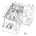
- a device 1 is illustrated, with which stacks 4 formed in a collating machine 2 from standing sheets 3 arranged in a row can be transported from a stack support 5 into an intermediate storage area 6, the sheets 3 being pressed together in this way perpendicular to the stacking direction and be strapped.
- the printed sheets 3, as disclosed in EP 1 199 275 A1 are fed in a shingled formation to the stacking support 5 via a deflection device 8 and placed in a row on a moving front support element 7 until a subsequent support element closes the stack 4 at the rear end.
- the loose stack 4 then reaches its end position on the stack support 5. This situation is illustrated by FIGS. 1 to 3.
- a movable pliers 10 is provided above the stack support 5, which presses the stack 4 at the ends and after lifting from the stack support 5 into an adjacent one Strapping station 11 offset, where it is encompassed by a band (not visible), is further transferred to a storage table 12 or to the clipboard 6.
- a pallet 13 on which the stacks 4 are placed next to and on top of one another. Further transport takes place with a pallet truck or forklift.
- a loadable vehicle could also be provided instead of one or more pallets 13.
- the pliers 10, which are formed from two clamping jaws 14, 15, are arranged so that they can be moved in a first conveying direction 7 from the stacking support 5 into the clipboard 6 by means of a bridge support 16 which is arranged on a support frame transversely to its longitudinal extent.
- the clipboard 6 can be designed as an automatic palletizing device.
- the tongs 10 are arranged on the bridge support 16 such that they can be moved transversely to the first conveying direction F.
- the pliers 10 are designed to be rotatable about a vertical axis.
- the bridge girder 16 has rollers (not shown) at the ends, which are continuously supported in lateral web girders 17, 18.
- the bridge girder 16 is connected to two rotating traction means 19, which are driven parallel to the first conveying direction F by an electric motor 20 fastened to the support frame 9.
- a common drive shaft 21 is provided, on each of which pulleys assigned to a traction means 19 are fastened, on which a toothed belt rotates.
- the clamping jaws 14, 15 of the pliers 10 are in turn fastened to an adjustable support 22 below the bridge support 16. That is, the carrier 22 is guided on vertical arms 23 which are fastened to the bridge carrier 16. The carrier 22 is raised and lowered by means of a winch-like elevator 24 which is fastened on the bridge carrier 16. The height of the pliers 10 is controlled by a rotary encoder and pulling straps 25 are provided as holding elements.
- the tongs 10 are actuated by a piston-cylinder unit 26 attached to the carrier 22. That is, the immovable clamping jaw 15 is aligned with the front end of the stack 4, so that the pliers 10 are only opened by a clamping jaw 14. However, this does not rule out that the position of the immovable clamping jaw 15 can be changed.
- the mode of operation of the device 1 alternatively allows the stack 4 on the stack support 5 to be gripped in different positions by the pliers 10 and placed in the clipboard 6 offset to the receiving position. It is therefore expedient if both clamping jaws 14, 15 of the pliers 10 can be driven, ie, for example, each clamping jaw 14, 15 is assigned a piston-cylinder unit which are actuated together. It is advantageous here if the clamping jaws 14, 15 are aligned approximately symmetrically on the stack 4 or that the position of the stack 4 is detected and the clamping jaw is then controlled.
- clamping jaws 14, 15 could pass through a rack and pinion gear attached to the carrier 22 is actuated be, for example, such that a between the jaws 14, 15 arranged gear on two opposite Racks acts, each with a jaw 14, 15th are connected.
- FIGS. 1 to 3 show, in a schematic arrangement of the device 1, a bar delivery device, referred to as a collecting device 2, to which a scaly stream 27 of printing sheets 3 are fed, which run into the bar delivery device from a printing machine (not visible) and over the opposite side a deflection device 8 can be turned. Following the deflection device 8, the shingled stream 27 flows into a stack support 5 on which a stack 4 of printed sheets 3 standing on the fold develops in the horizontal direction.
- FIGS. 1 and 2 show an imperfect stack 4, which has reached a board insertion station 28, through which the front and rear ends of a stack 4 are provided with an end board. With 29 a board magazine is noted in which boards are provided.
- exemplary embodiments can be found in EP 0 623 542 A1 and EP 1 199 275 A1.
- the present device 1 is constructed in such a way that it can be used as a fully automatic machine behind a printing press.
Abstract
Description
Einrichtungen dieser Art werden zur Entsorgung von sog. Stangenauslegern gemäss EP 0 623 542 A1 und EP 1 199 275 A1 verwendet.
Eine bekannte Entsorgung eines Stangenauslegers 327 vermittelt ein Prospekt 327.889 MÜLLER MARTINI. Die auf dem Stangenausleger produzierten liegenden Stapel aus stehend aneinandergereihten Druckbogen werden auf einer Auflage zusammengetragen resp. gesammelt, zusammengepresst und umreift. Danach werden die fertigen Stangen resp. Stapel manuell, seitlich über einen Rollentisch von der Auflage verschoben und anschliessend von einem Kran erfasst und auf Paletten abgesetzt.
Dies bedingt sowohl eine Zange für den Press- und Umreifungsvorgang im Stangenausleger wie auch eine weitere Zange für den Transport des abgebundenen Stapels in die Zwischenablage.
- Fig. 1
- eine räumliche Darstellung der erfindungsgemässen Einrichtung,
- Fig. 2
- eine Seitenansicht der in Fig. 1 dargestellten Einrichtung und
- Fig. 3
- einen Grundriss der in Fig. 2 gezeigten Einrichtung.
Zuvor werden die Druckbogen 3 wie in der EP 1 199 275 A1 offenbart in geschuppter Formation über eine Umlenkvorrichtung 8 der Stapelauflage 5 zugeführt und an einem sich fortbewegenden vorderen Stützelement 7 aneinandergereiht aufgestellt, bis ein folgendes Stützelement den Stapel 4 an dem hinteren Ende abschliesst. Danach erreicht der lose Stapel 4 seine Endposition auf der Stapelauflage 5. Diese Situation wird durch die Fig. 1 bis 3 vermittelt.
Um eine kreuzweise Lagerung der Stapel 4 in der Zwischenablage 6 vorsehen zu können, ist die Zange 10 um eine senkrechte Achse drehbar ausgebildet.
Der Brückenträger 16 weist an den Enden Laufrollen (nicht dargestellt) auf, die in seitlichen Bahnträgern 17, 18 laufend gelagert sind. Der Brückenträger 16 ist mit zwei umlaufenden Zugmitteln 19 verbunden, die parallel zur ersten Förderrichtung F von einem am Traggestell 9 befestigten Elektromotor 20 angetrieben sind. Zur Uebertragung einer gleichmässigen Drehbewegung auf beide Zugmittel 19 ist eine gemeinsame Antriebswelle 21 vorgesehen, an der jeweils einem Zugmittel 19 zugeordnete Pulleys befestigt sind, an denen ein Zahnriemen umläuft.
Die Zange 10 wird durch eine am Träger 22 befestigte Kolben-Zylinder-Einheit 26 betätigt. D.h., die unbewegliche Klemmbacke 15 ist auf das vordere Ende des Stapels 4 ausgerichtet, sodass die Zange 10 nurmehr durch eine Klemmbacke 14 geöffnet wird. Dies schliesst jedoch nicht aus, dass die Position der unbeweglichen Klemmbacke 15 verändert werden kann.
Die Funktionsweise der Einrichtung 1 erlaubt es alternativ, dass der Stapel 4 auf der Stapelauflage 5 in unterschiedlichen Position von der Zange 10 erfasst werden kann und in der Zwischenablage 6 versetzt zur Aufnahmeposition abgesetzt wird. Somit ist es zweckmässig, wenn beide Klemmbacken 14, 15 der Zange 10 antreibbar sind, d.h. jeder Klemmbacke 14, 15 ist beispielsweise eine Kolben-Zylinder-Einheit zugeordnet, die gemeinsam betätigt werden. Hierbei ist es vorteilhaft, wenn die Klemmbacken 14, 15 etwa symmetrisch auf den Stapel 4 ausgerichtet werden oder dass die Lage des Stapels 4 detektiert wird und die Klemmbacke danach gesteuert werden.
Wie schon eingangs erwähnt können Ausführungsbeispiele den EP 0 623 542 A1 und EP 1 199 275 A1 entnommen werden.
Die vorliegende Einrichtung 1 ist derart konstruiert, dass sie als Vollautomat hinter einer Druckmaschine einsetzbar ist.
Claims (14)
- Einrichtung (1) zum Transport eines in einer Sammelvorrichtung (2) aus stehend aneinandergereihten Druckbogen (3) gebildeten, liegenden Stapels (4), von einer Stapelauflage (5) in eine Zwischenablage (6), dadurch gekennzeichnet, dass oberhalb der Stapelauflage (5) eine den Stapel (4) an den Enden zusammenpressende, senkrecht und horizontal verfahrbare Zange (10) angeordnet ist, die einen umreiften Stapel (4) von der Stapelauflage (5) in die benachbarte Zwischenablage (6) überführt.
- Einrichtung (1) zum Transport eines in einer Sammelvorrichtung (2) aus stehend aneinandergereihten Druckbogen (3) gebildeten, liegenden Stapels (4), von einer Stapelauflage (5) in eine Zwischenablage (6), dadurch gekennzeichnet, dass oberhalb der Stapelauflage (5) eine den Stapel (4) an den Enden zusammenpressende, senkrecht und horizontal verfahrbare Zange (10) angeordnet ist, die den Stapel (4) von der Stapelauflage (5) über eine zum Umreifen bestimmte, benachbarte Umreifungsstation (11) in die anschliessende Zwischenstation (6) überführt.
- Einrichtung (1) nach Anspruch 1 oder 2, dadurch gekennzeichnet, dass die aus zwei Klemmbacken (14, 15) bestehende Zange (10) an einem Traggestell (9) in einer ersten Förderrichtung (F) von der Stapelauflage (5) in die Zwischenablage (6) verfahrbar ist.
- Einrichtung (1) nach Anspruch 3, dadurch gekennzeichnet, dass die Zwischenablage (6) als Palettierautomat ausgebildet ist.
- Einrichtung (1) nach Anspruch 4, dadurch gekennzeichnet, dass die Zange (10) quer zur ersten Förderrichtung (F) an einem fahrbaren Brückenträger (16) verfahrbar ist.
- Einrichtung (1) nach einem der Ansprüche 3 bis 5, dadurch gekennzeichnet, dass die Zange (10) um eine senkrechte Achse drehbar ausgebildet ist.
- Einrichtung (1) nach einem der Ansprüche 3 bis 6, dadurch gekennzeichnet, dass die Zange (10) an einem quer zur ersten Förderrichtung (F) angeordneten, fahrbar angetriebenen Brückenträger (16) hängend befestigt ist.
- Einrichtung (1) nach Anspruch 7, dadurch gekennzeichnet, dass der Brückenträger (16) endseitig an mit dem Traggestell (9) verbundenen Bahnträgern (17, 18) fahrbar ausgebildet ist.
- Einrichtung (1) nach Anspruch 8, dadurch gekennzeichnet, dass der Brückenträger (16) mit wenigstens einem endlos umlaufenden Zugmittel (19) antriebsverbunden ist.
- Einrichtung (1) nach Anspruch 9, mit zwei den Brückenträger (16) entlang den Bahnträgern (17, 18) antreibenden Zugmitteln (19), dadurch gekennzeichnet, dass die Zugmittel (19) als Zahnriemen ausgebildet und mit einer gemeinsamen Antriebswelle (21) eines am Traggestell (9) befestigten Motors (20) antriebsverbunden sind.
- Einrichtung (1) nach einem der Ansprüche 7 bis 10, dadurch gekennzeichnet, dass die Klemmbacken (14, 15) der Zange (10) an einem unterhalb des Brückenträgers (16), quer zur ersten Förderrichtung (F) sich erstreckenden, senkrecht antreibbar geführten Träger (22) verstellbar befestigt sind.
- Einrichtung (1) nach Anspruch 11, dadurch gekennzeichnet, dass der Träger (22) mit einer an dem Brückenträger (16) befestigten Antriebsvorrichtung höhenverstellbar verbunden ist.
- Einrichtung (1) nach einem der Ansprüche 11 und 12, dadurch gekennzeichnet, dass wenigstens eine der Klemmbacken (14, 15) der Zange (10) am Träger (22) beweglich ausgebildet ist.
- Einrichtung (1) nach Anspruch 13, dadurch gekennzeichnet, dass die der beweglichen Klemmbacke (14, 15) gegenüberliegende Klemmbacke (14, 15) dem in Stapelbildungsrichtung entgegengesetzten Ende des Stapels (4) zugeordnet ist.
Priority Applications (4)
| Application Number | Priority Date | Filing Date | Title |
|---|---|---|---|
| DE50211920T DE50211920D1 (de) | 2002-07-02 | 2002-07-02 | Einrichtung zum Transport eines in einer Zusammentragmaschine aus stehend aneinandergereihten Druckbogen gebildeten, auf einer Auflage liegenden Stapels |
| EP02405554A EP1378472B1 (de) | 2002-07-02 | 2002-07-02 | Einrichtung zum Transport eines in einer Zusammentragmaschine aus stehend aneinandergereihten Druckbogen gebildeten, auf einer Auflage liegenden Stapels |
| JP2003270231A JP4523247B2 (ja) | 2002-07-02 | 2003-07-01 | 丁合機内において互いに隣接して起立するよう整列された印刷紙から形成され載置台上に載置された積重ね体を搬送する装置 |
| US10/609,372 US7168910B2 (en) | 2002-07-02 | 2003-07-01 | Device for transporting a horizontal stack positioned on a support and formed in a gathering machine with upright, lined-up signatures |
Applications Claiming Priority (1)
| Application Number | Priority Date | Filing Date | Title |
|---|---|---|---|
| EP02405554A EP1378472B1 (de) | 2002-07-02 | 2002-07-02 | Einrichtung zum Transport eines in einer Zusammentragmaschine aus stehend aneinandergereihten Druckbogen gebildeten, auf einer Auflage liegenden Stapels |
Publications (2)
| Publication Number | Publication Date |
|---|---|
| EP1378472A1 true EP1378472A1 (de) | 2004-01-07 |
| EP1378472B1 EP1378472B1 (de) | 2008-03-19 |
Family
ID=29719807
Family Applications (1)
| Application Number | Title | Priority Date | Filing Date |
|---|---|---|---|
| EP02405554A Expired - Lifetime EP1378472B1 (de) | 2002-07-02 | 2002-07-02 | Einrichtung zum Transport eines in einer Zusammentragmaschine aus stehend aneinandergereihten Druckbogen gebildeten, auf einer Auflage liegenden Stapels |
Country Status (4)
| Country | Link |
|---|---|
| US (1) | US7168910B2 (de) |
| EP (1) | EP1378472B1 (de) |
| JP (1) | JP4523247B2 (de) |
| DE (1) | DE50211920D1 (de) |
Cited By (5)
| Publication number | Priority date | Publication date | Assignee | Title |
|---|---|---|---|---|
| DE102004009584A1 (de) * | 2004-02-25 | 2005-09-15 | Focke & Co.(Gmbh & Co. Kg) | Vorrichtung zum Herstellen und Palettieren von Kartonpackungen |
| EP1790603A1 (de) | 2005-11-23 | 2007-05-30 | Müller Martini Holding AG | Verfahren und Einrichtung zum Zwischenlagern von Stapeln |
| EP1816098A1 (de) | 2006-02-02 | 2007-08-08 | Müller Martini Holding AG | Verfahren und Vorrichtung zur Bildung von Stapeln |
| EP2147877A1 (de) | 2008-07-24 | 2010-01-27 | Ferag AG | Palettiervorrichtung und Verarbeitungssystem mit einer solchen Vorrichtung |
| CN102689704A (zh) * | 2011-03-22 | 2012-09-26 | 株式会社东芝 | 累积和捆绑设备 |
Families Citing this family (11)
| Publication number | Priority date | Publication date | Assignee | Title |
|---|---|---|---|---|
| US8000837B2 (en) | 2004-10-05 | 2011-08-16 | J&L Group International, Llc | Programmable load forming system, components thereof, and methods of use |
| US9650215B2 (en) | 2013-05-17 | 2017-05-16 | Intelligrated Headquarters Llc | Robotic carton unloader |
| MX2015015750A (es) | 2013-05-17 | 2016-09-08 | Intelligrated Headquarters Llc | Aparáto robótico de descarga de cajas de cartón. |
| US9487361B2 (en) | 2013-05-17 | 2016-11-08 | Intelligrated Headquarters Llc | Robotic carton unloader |
| US10336562B2 (en) | 2013-05-17 | 2019-07-02 | Intelligrated Headquarters, Llc | Robotic carton unloader |
| US9493316B2 (en) | 2013-07-30 | 2016-11-15 | Intelligrated Headquarters Llc | Robotic carton unloader |
| CN108584471B (zh) | 2013-08-28 | 2020-05-29 | 因特利格兰特总部有限责任公司 | 机器人纸箱卸载机 |
| US9623569B2 (en) | 2014-03-31 | 2017-04-18 | Intelligrated Headquarters, Llc | Autonomous truck loader and unloader |
| US10518916B2 (en) * | 2016-05-27 | 2019-12-31 | Daniel S. Underwood | Material processing system |
| US10597235B2 (en) | 2016-10-20 | 2020-03-24 | Intelligrated Headquarters, Llc | Carton unloader tool for jam recovery |
| CN108190143A (zh) * | 2018-03-09 | 2018-06-22 | 崔浩轩 | 一种打印纸生产设备输出收集装置 |
Citations (5)
| Publication number | Priority date | Publication date | Assignee | Title |
|---|---|---|---|---|
| US4419035A (en) * | 1982-04-21 | 1983-12-06 | Stobb, Inc. | Method and apparatus for moving bundles of sheets |
| US4674934A (en) * | 1984-05-11 | 1987-06-23 | Grapha-Holding Ag | Apparatus for stacking paper sheets and the like |
| EP0339002A2 (de) * | 1988-04-18 | 1989-10-25 | O.M.G. di GIORGIO PESSINA E ALDO PEROBELLI S.n.c. | Kontinuierlicher Signaturenpaketausleger, versehen mit einer speziellen Vorrichtung für die Querverschiebung des zusammengefassten Paketes |
| EP0623542A1 (de) * | 1993-05-07 | 1994-11-09 | Grapha-Holding Ag | Einrichtung zur Bildung eines sich senkrecht zu den stehend aneinandergereihten Druckbogen erstreckenden Stapels |
| JPH08113210A (ja) * | 1994-10-07 | 1996-05-07 | Dainippon Printing Co Ltd | 結束装置 |
Family Cites Families (22)
| Publication number | Priority date | Publication date | Assignee | Title |
|---|---|---|---|---|
| US3076673A (en) * | 1962-01-16 | 1963-02-05 | Cullen Friestedt Company | Lifter mechanism with horizontally extensible jaw-supporting arms |
| JPS5213132B2 (de) * | 1972-02-05 | 1977-04-12 | ||
| DE2532297C3 (de) * | 1975-07-18 | 1981-02-12 | Gruner + Jahr Ag & Co, 2210 Itzehoe | Anordnung zum Lagern und Transportieren der aus einer Druckmaschine herausgeführten Druckerzeugnisse in Stapelform |
| US4519740A (en) * | 1983-06-17 | 1985-05-28 | Stobb, Inc. | Apparatus and method for palletizing bundles of sheets |
| US4591198A (en) * | 1984-02-16 | 1986-05-27 | Monforte Robotics, Inc. | Robotic end effectors |
| JPS60180223U (ja) * | 1984-05-11 | 1985-11-29 | 喜多 将夫 | 搬送物の移載装置 |
| US4671934A (en) * | 1986-04-18 | 1987-06-09 | Buckman Laboratories, Inc. | Aminophosphonic acid/phosphate mixtures for controlling corrosion of metal and inhibiting calcium phosphate precipitation |
| US4658715A (en) * | 1986-04-14 | 1987-04-21 | Stobb Inc. | System for automating the palletizing of bundles |
| GB8709851D0 (en) * | 1987-04-25 | 1987-05-28 | Langston Machine | Stacking boxes of corrugated board |
| US5098254A (en) * | 1988-09-12 | 1992-03-24 | Fmc Corporation | Proximity detection means on a palletizer hand assembly |
| DE3835032A1 (de) * | 1988-10-14 | 1990-04-19 | Niepmann Traylift Transport | Verfahren und vorrichtung zum entstapeln von blockweise auf paletten gestapelten zuschnitten |
| ES2030299T3 (es) * | 1988-12-31 | 1992-10-16 | System Gmbh | Robot paletizador. |
| JPH02193818A (ja) * | 1989-01-23 | 1990-07-31 | Okura Yusoki Co Ltd | パレット荷積み装置 |
| JPH02193819A (ja) * | 1989-01-23 | 1990-07-31 | Okura Yusoki Co Ltd | 物品保持装置 |
| IT1252449B (it) * | 1991-07-22 | 1995-06-16 | Gd Spa | Procedimento e dispositivo per ordinare pile di sbozzati in una macchina confezionatrice |
| EP0530426B1 (de) * | 1991-09-02 | 1993-07-07 | Fabriques De Tabac Reunies S.A. | Greif- und Übertragungszange |
| IT1256310B (it) * | 1992-11-11 | 1995-11-30 | Ocme | Dispositivo per il prelievo,la movimentazione e la deposizione di una pila di fustellati |
| IT1263434B (it) * | 1993-06-16 | 1996-08-05 | Gd Spa | Unita' di prelievo ed alimentazione di pile di sbozzati |
| US5674049A (en) * | 1994-06-17 | 1997-10-07 | Automatic Handling, Inc. | Roll handling apparatus |
| EP0995555A1 (de) * | 1998-10-15 | 2000-04-26 | Tecan AG | Robotarm |
| US6315516B1 (en) * | 1998-10-19 | 2001-11-13 | Lemo Maschinenbau Gmbh | Device for delivering stackable bag packages, particularly plastic bags with a bottom fold |
| EP1199275B1 (de) | 2000-10-20 | 2004-07-14 | Grapha-Holding AG | Einrichtung zur Bildung eines Stapels aneinandergereihter Druckbogen |
-
2002
- 2002-07-02 DE DE50211920T patent/DE50211920D1/de not_active Expired - Lifetime
- 2002-07-02 EP EP02405554A patent/EP1378472B1/de not_active Expired - Lifetime
-
2003
- 2003-07-01 US US10/609,372 patent/US7168910B2/en not_active Expired - Fee Related
- 2003-07-01 JP JP2003270231A patent/JP4523247B2/ja not_active Expired - Fee Related
Patent Citations (5)
| Publication number | Priority date | Publication date | Assignee | Title |
|---|---|---|---|---|
| US4419035A (en) * | 1982-04-21 | 1983-12-06 | Stobb, Inc. | Method and apparatus for moving bundles of sheets |
| US4674934A (en) * | 1984-05-11 | 1987-06-23 | Grapha-Holding Ag | Apparatus for stacking paper sheets and the like |
| EP0339002A2 (de) * | 1988-04-18 | 1989-10-25 | O.M.G. di GIORGIO PESSINA E ALDO PEROBELLI S.n.c. | Kontinuierlicher Signaturenpaketausleger, versehen mit einer speziellen Vorrichtung für die Querverschiebung des zusammengefassten Paketes |
| EP0623542A1 (de) * | 1993-05-07 | 1994-11-09 | Grapha-Holding Ag | Einrichtung zur Bildung eines sich senkrecht zu den stehend aneinandergereihten Druckbogen erstreckenden Stapels |
| JPH08113210A (ja) * | 1994-10-07 | 1996-05-07 | Dainippon Printing Co Ltd | 結束装置 |
Non-Patent Citations (1)
| Title |
|---|
| PATENT ABSTRACTS OF JAPAN vol. 1996, no. 09 30 September 1996 (1996-09-30) * |
Cited By (10)
| Publication number | Priority date | Publication date | Assignee | Title |
|---|---|---|---|---|
| DE102004009584A1 (de) * | 2004-02-25 | 2005-09-15 | Focke & Co.(Gmbh & Co. Kg) | Vorrichtung zum Herstellen und Palettieren von Kartonpackungen |
| US7596926B2 (en) | 2004-02-25 | 2009-10-06 | Focke & Co. (Gmbh & Co. Kg) | Device for producing and palleting packaging boxes |
| EP1790603A1 (de) | 2005-11-23 | 2007-05-30 | Müller Martini Holding AG | Verfahren und Einrichtung zum Zwischenlagern von Stapeln |
| EP1816098A1 (de) | 2006-02-02 | 2007-08-08 | Müller Martini Holding AG | Verfahren und Vorrichtung zur Bildung von Stapeln |
| US7862020B2 (en) | 2006-02-02 | 2011-01-04 | Mueller Martini Holding Ag | Method for forming stacks from upright positioned, successively lined up signatures and arrangement for realizing the method |
| EP2147877A1 (de) | 2008-07-24 | 2010-01-27 | Ferag AG | Palettiervorrichtung und Verarbeitungssystem mit einer solchen Vorrichtung |
| CN102689704A (zh) * | 2011-03-22 | 2012-09-26 | 株式会社东芝 | 累积和捆绑设备 |
| US8746135B2 (en) | 2011-03-22 | 2014-06-10 | Kabushiki Kaisha Toshiba | Accumulating and strapping apparatus |
| US8925448B2 (en) | 2011-03-22 | 2015-01-06 | Kabushiki Kaisha Toshiba | Accumulating and strapping apparatus |
| CN102689704B (zh) * | 2011-03-22 | 2015-07-01 | 株式会社东芝 | 累积和捆绑设备 |
Also Published As
| Publication number | Publication date |
|---|---|
| JP4523247B2 (ja) | 2010-08-11 |
| EP1378472B1 (de) | 2008-03-19 |
| DE50211920D1 (de) | 2008-04-30 |
| JP2004035268A (ja) | 2004-02-05 |
| US20040096309A1 (en) | 2004-05-20 |
| US7168910B2 (en) | 2007-01-30 |
Similar Documents
| Publication | Publication Date | Title |
|---|---|---|
| EP1378472B1 (de) | Einrichtung zum Transport eines in einer Zusammentragmaschine aus stehend aneinandergereihten Druckbogen gebildeten, auf einer Auflage liegenden Stapels | |
| EP0623542B1 (de) | Einrichtung zur Bildung eines sich senkrecht zu den stehend aneinandergereihten Druckbogen erstreckenden Stapels | |
| CH671566A5 (de) | ||
| DE3314204A1 (de) | Verfahren und vorrichtung zum bewegen von aus bogen gebildeten buendeln | |
| DE4203118C2 (de) | Vorrichtung zum Ergreifen und Transportieren von Stapeln flacher Gegenstände | |
| DE10356563A1 (de) | Vorrichtung zum Palettieren von Kartonagen mit Aufnahmestation mit Seiteneinführung | |
| DE2508745C2 (de) | Vorrichtung zum Aufstauen vereinzelt mittels einer Transportvorrichtung zugeförderter Papierbögen zu Stapeln und zum Weitertransportieren dieser Stapel | |
| DE10022272B4 (de) | Vorrichtung zum Palettieren von Paketen | |
| DE3414996C1 (de) | Vorrichtung zum Abschieben von auf einer Trageinrichtung abgelegten Stapeln oder Paketen | |
| DE3540203C2 (de) | Vorrichtung zum Fördern von Papierstapeln | |
| EP1405809A1 (de) | Einrichtung zur Herstellung von Stapelpaketen | |
| EP0097308B1 (de) | Vorrichtung und Verfahren zum automatischen Palettieren von gebündelten Stapeln aus Zeitungen u. dgl. | |
| EP1491477A1 (de) | Vorrichtung zum Bilden von Stapeln | |
| DE2707191A1 (de) | Vorrichtung und verfahren zur handhabung von aus blaettern gebildeten buendeln, insbesondere in der graphischen industrie | |
| EP1611039A1 (de) | Transporteinrichtung, insbesondere für plattenförmige werkstücke | |
| DE4236362A1 (de) | Ausfuhreinrichtung für Buchfadenheftmaschine | |
| DE102009040792A1 (de) | Palettenentstapler | |
| EP0210172B1 (de) | Vorrichtung zum stapeln dünnwandiger formteile | |
| EP0875473B1 (de) | Einrichtung zum Abstapeln von aus Einzelplatten oder Plattenpaketen bestehendem Plattenmaterial | |
| EP0691295B1 (de) | Plattenbeschickungseinrichtung für Plattenaufteilsägen | |
| DE2311871C3 (de) | Vorrichtung zum ausgerichteten Auslegen von Palettenreihen | |
| DE2220846A1 (de) | Verfahren und vorrichtung zum zerlegen von ziegelstapeln | |
| DE2557178B2 (de) | Stapelvorrichtung für Dachziegel | |
| EP0679534A1 (de) | Ausfuhreinrichtung für Buchfadenheftmaschine | |
| DE19507387A1 (de) | Verfahren und Vorrichtung zum Sammeln, Verpacken und/oder Abdichten von Glastafeln in Glastafelpaketen |
Legal Events
| Date | Code | Title | Description |
|---|---|---|---|
| PUAI | Public reference made under article 153(3) epc to a published international application that has entered the european phase |
Free format text: ORIGINAL CODE: 0009012 |
|
| AK | Designated contracting states |
Kind code of ref document: A1 Designated state(s): AT BE BG CH CY CZ DE DK EE ES FI FR GB GR IE IT LI LU MC NL PT SE SK TR |
|
| AX | Request for extension of the european patent |
Extension state: AL LT LV MK RO SI |
|
| 17P | Request for examination filed |
Effective date: 20040517 |
|
| AKX | Designation fees paid |
Designated state(s): CH DE FR GB IT LI |
|
| RBV | Designated contracting states (corrected) |
Designated state(s): CH DE FR GB IT LI SE |
|
| GRAP | Despatch of communication of intention to grant a patent |
Free format text: ORIGINAL CODE: EPIDOSNIGR1 |
|
| GRAS | Grant fee paid |
Free format text: ORIGINAL CODE: EPIDOSNIGR3 |
|
| GRAA | (expected) grant |
Free format text: ORIGINAL CODE: 0009210 |
|
| AK | Designated contracting states |
Kind code of ref document: B1 Designated state(s): CH DE FR GB IT LI SE |
|
| REG | Reference to a national code |
Ref country code: GB Ref legal event code: FG4D Free format text: NOT ENGLISH |
|
| REG | Reference to a national code |
Ref country code: CH Ref legal event code: EP |
|
| REF | Corresponds to: |
Ref document number: 50211920 Country of ref document: DE Date of ref document: 20080430 Kind code of ref document: P |
|
| REG | Reference to a national code |
Ref country code: SE Ref legal event code: TRGR |
|
| ET | Fr: translation filed | ||
| PLBE | No opposition filed within time limit |
Free format text: ORIGINAL CODE: 0009261 |
|
| STAA | Information on the status of an ep patent application or granted ep patent |
Free format text: STATUS: NO OPPOSITION FILED WITHIN TIME LIMIT |
|
| 26N | No opposition filed |
Effective date: 20081222 |
|
| REG | Reference to a national code |
Ref country code: FR Ref legal event code: PLFP Year of fee payment: 14 |
|
| PGFP | Annual fee paid to national office [announced via postgrant information from national office to epo] |
Ref country code: DE Payment date: 20150715 Year of fee payment: 14 Ref country code: GB Payment date: 20150723 Year of fee payment: 14 |
|
| PGFP | Annual fee paid to national office [announced via postgrant information from national office to epo] |
Ref country code: FR Payment date: 20150727 Year of fee payment: 14 Ref country code: SE Payment date: 20150723 Year of fee payment: 14 |
|
| PGFP | Annual fee paid to national office [announced via postgrant information from national office to epo] |
Ref country code: IT Payment date: 20150731 Year of fee payment: 14 |
|
| PGFP | Annual fee paid to national office [announced via postgrant information from national office to epo] |
Ref country code: CH Payment date: 20151021 Year of fee payment: 14 |
|
| REG | Reference to a national code |
Ref country code: DE Ref legal event code: R119 Ref document number: 50211920 Country of ref document: DE |
|
| REG | Reference to a national code |
Ref country code: CH Ref legal event code: PL |
|
| REG | Reference to a national code |
Ref country code: SE Ref legal event code: EUG |
|
| GBPC | Gb: european patent ceased through non-payment of renewal fee |
Effective date: 20160702 |
|
| PG25 | Lapsed in a contracting state [announced via postgrant information from national office to epo] |
Ref country code: SE Free format text: LAPSE BECAUSE OF NON-PAYMENT OF DUE FEES Effective date: 20160703 Ref country code: FR Free format text: LAPSE BECAUSE OF NON-PAYMENT OF DUE FEES Effective date: 20160801 Ref country code: DE Free format text: LAPSE BECAUSE OF NON-PAYMENT OF DUE FEES Effective date: 20170201 Ref country code: LI Free format text: LAPSE BECAUSE OF NON-PAYMENT OF DUE FEES Effective date: 20160731 Ref country code: CH Free format text: LAPSE BECAUSE OF NON-PAYMENT OF DUE FEES Effective date: 20160731 |
|
| REG | Reference to a national code |
Ref country code: FR Ref legal event code: ST Effective date: 20170331 |
|
| PG25 | Lapsed in a contracting state [announced via postgrant information from national office to epo] |
Ref country code: GB Free format text: LAPSE BECAUSE OF NON-PAYMENT OF DUE FEES Effective date: 20160702 |
|
| PG25 | Lapsed in a contracting state [announced via postgrant information from national office to epo] |
Ref country code: IT Free format text: LAPSE BECAUSE OF NON-PAYMENT OF DUE FEES Effective date: 20160702 |