EP0339002A2 - Kontinuierlicher Signaturenpaketausleger, versehen mit einer speziellen Vorrichtung für die Querverschiebung des zusammengefassten Paketes - Google Patents
Kontinuierlicher Signaturenpaketausleger, versehen mit einer speziellen Vorrichtung für die Querverschiebung des zusammengefassten Paketes Download PDFInfo
- Publication number
- EP0339002A2 EP0339002A2 EP89830168A EP89830168A EP0339002A2 EP 0339002 A2 EP0339002 A2 EP 0339002A2 EP 89830168 A EP89830168 A EP 89830168A EP 89830168 A EP89830168 A EP 89830168A EP 0339002 A2 EP0339002 A2 EP 0339002A2
- Authority
- EP
- European Patent Office
- Prior art keywords
- package
- previous
- machine
- platform
- signature
- Prior art date
- Legal status (The legal status is an assumption and is not a legal conclusion. Google has not performed a legal analysis and makes no representation as to the accuracy of the status listed.)
- Granted
Links
Images


Classifications
-
- B—PERFORMING OPERATIONS; TRANSPORTING
- B65—CONVEYING; PACKING; STORING; HANDLING THIN OR FILAMENTARY MATERIAL
- B65H—HANDLING THIN OR FILAMENTARY MATERIAL, e.g. SHEETS, WEBS, CABLES
- B65H31/00—Pile receivers
- B65H31/30—Arrangements for removing completed piles
- B65H31/3081—Arrangements for removing completed piles by acting on edge of the pile for moving it along a surface, e.g. by pushing
-
- B—PERFORMING OPERATIONS; TRANSPORTING
- B65—CONVEYING; PACKING; STORING; HANDLING THIN OR FILAMENTARY MATERIAL
- B65H—HANDLING THIN OR FILAMENTARY MATERIAL, e.g. SHEETS, WEBS, CABLES
- B65H31/00—Pile receivers
- B65H31/04—Pile receivers with movable end support arranged to recede as pile accumulates
- B65H31/06—Pile receivers with movable end support arranged to recede as pile accumulates the articles being piled on edge
-
- B—PERFORMING OPERATIONS; TRANSPORTING
- B65—CONVEYING; PACKING; STORING; HANDLING THIN OR FILAMENTARY MATERIAL
- B65H—HANDLING THIN OR FILAMENTARY MATERIAL, e.g. SHEETS, WEBS, CABLES
- B65H2301/00—Handling processes for sheets or webs
- B65H2301/40—Type of handling process
- B65H2301/42—Piling, depiling, handling piles
- B65H2301/421—Forming a pile
- B65H2301/4214—Forming a pile of articles on edge
- B65H2301/42146—Forming a pile of articles on edge by introducing articles from above
-
- B—PERFORMING OPERATIONS; TRANSPORTING
- B65—CONVEYING; PACKING; STORING; HANDLING THIN OR FILAMENTARY MATERIAL
- B65H—HANDLING THIN OR FILAMENTARY MATERIAL, e.g. SHEETS, WEBS, CABLES
- B65H2301/00—Handling processes for sheets or webs
- B65H2301/40—Type of handling process
- B65H2301/42—Piling, depiling, handling piles
- B65H2301/422—Handling piles, sets or stacks of articles
- B65H2301/4224—Gripping piles, sets or stacks of articles
- B65H2301/42242—Gripping piles, sets or stacks of articles by acting on the outermost articles of the pile for clamping the pile
-
- B—PERFORMING OPERATIONS; TRANSPORTING
- B65—CONVEYING; PACKING; STORING; HANDLING THIN OR FILAMENTARY MATERIAL
- B65H—HANDLING THIN OR FILAMENTARY MATERIAL, e.g. SHEETS, WEBS, CABLES
- B65H2301/00—Handling processes for sheets or webs
- B65H2301/40—Type of handling process
- B65H2301/42—Piling, depiling, handling piles
- B65H2301/422—Handling piles, sets or stacks of articles
- B65H2301/4226—Delivering, advancing piles
- B65H2301/42266—Delivering, advancing piles by acting on edge of the pile for moving it along a surface, e.g. pushing
-
- B—PERFORMING OPERATIONS; TRANSPORTING
- B65—CONVEYING; PACKING; STORING; HANDLING THIN OR FILAMENTARY MATERIAL
- B65H—HANDLING THIN OR FILAMENTARY MATERIAL, e.g. SHEETS, WEBS, CABLES
- B65H2701/00—Handled material; Storage means
- B65H2701/10—Handled articles or webs
- B65H2701/19—Specific article or web
- B65H2701/1932—Signatures, folded printed matter, newspapers or parts thereof and books
Definitions
- the subject of this invention is a continuous signature stacker machine, provided with a special device for transversely ejecting the assembled package.
- the signatures coming out of folding machines are usually collected into packages in order to be then transferred to other bookbindery machines.
- said conventional machines usually require important modification and setup operations for any variation of the dimensions of the signatures to be stacked.
- An object of this invention is to overcome the previous strictly ly mentioned drawbacks, by providing a signature stacker machine which doesn't require any interruption of operations during the process of picking up the assembled package.
- a particular object of this invention is to provide a signature stacker machine which is very reliable and of a simple construction.
- a further object of this invention is to provide a signature stacker machine which allows different size signatures to be handled, with minimum adjustments.
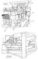
- a signature stacker machine substantially includes a platform, whereon the individual signatures are sequentially fed resting on the edge thereof, in order to progressively assemble a predetermined length package which is then transferred across the platform, in a transverse direction, by means of a special ejecting device, which is adapted to transfer said package directly on the platform of a further machine (for instance a strap applying machine); in particular, the package of signatures being assembled is opposed, at the forward moving front thereof, by a slide member, driven by a pair of chains and automatically repositionable, after the package has been formed and transferred, to an opposition location relative to a new package being formed.
- the subject signature stacker machine includes a roller feeder, shown in general at (1), with a press station provided downstream thereof, said station comprising a plurality of mutually opposed rollers (2).
- Said mutually opposed rollers are provided to subject the signatures (3) already folded and fed by un upstream folding machine, to a suitable pressure for the purpose of ejecting air from said signatures flattening them further, in order to improve the folding situation thereof.
- Said signatures are subsequently picked up by a belt system (4) which is adapted to give them a fish scale like arrangement and to forward them vertically upwards along a stretch 5.
- said signatures are transferred downwards (still under the action of the belt system mentioned above) while resting on the edges thereof, and they slide along the vertically downwards stretch, whereupon they get arranged in a vertical position along a sliding platform (7).
- pairs of chains drive the forward motion of a slide member (9), hooking up to one of their links by means of cogs arranged underneath a pair of small L-shaped arms, shown at (10), pivoted at (11) around a horizontal axis, at the base of said slide member.
- said small arms are provided, on the vertical of their pivoting axis, with a further small upwards extending arm (12) which carries, at the top thereof, a small coaxial idle wheel (13).
- a pressure action is established on said pairs of small wheels by the various signatures being deposited on the platform, which gradually form a package (14) having a progressively increasing thickness.
- the meshing engagement of said small cogs can be obtained as well by means of an electromagnet, or of a small pneumatic cylinder or the like.
- Slide member (9) is provided, at the front side thereof, with an adjustable screw (15) which, once said slide member has reached a predetermined limit position, is controlled to actuate a microswitch (16) which, in turn, actuates a package ejection device, indicated in general at (17).
- Said ejecting device is generally supported by a moving frame, adjustable on a stationary frame provided for the purpose. Said design arrangement allows the package to be ejected at both sides of the machine, without having to resort to complicated adjustment and control operations
- said design approach eliminates any projection out of the machine outline, both during manual withdrawal of the signatures and during automatic ejection thereof.
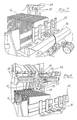
- the ejecting device is comprised of sliding rails (18) arranged transversely relative to said pair of chains (8), and adapted to form translation guides or seats for pairs of small diameter rollers (19).
- the latter support a carriage (20), which in turn carries two vertical arms shown at (21), connected by a lower horizontal cross member (22) which is in turn provided, at the ends thereof, with corresponding pivoting arms (23).
- the one facing towards the inner area of the platform is linked, by means of a first rod (24), to a lever (25), whose power receiving end is driven by a second rod (26) comprising the reciprocating armature of an electromagnet (27), or by an equivalent member.
- the arm mentioned above is provided, at the free end thereof, with at least a small roller (28) adapted to slide with the lowest possible friction, against the signatures, at the moment when the package is being ejected.
- said small roller there is provided, at both sides of the ejecting device, a small plate (29) whose function is to contain the package to be ejected, separating the same from the various other signatures which are meant to form a following package (14′).
- a vertically projecting member (30) carrying, at different heights, two or more separator blades (31) arranged stepwise at the package ejection side.
- said projecting member which is provided as well with a package holding plate, is fastened to the machine upper platform, and is comprised of mutually telescoped members.
- Said feature substantially makes member (30) constantly adjustable close to a side of the package, regardless of the size of the latter; furthermore, it allows said adjusting operation to be performed keeping to a minimum the room between the stack er machine and the following package processing station.
- said blades prevent an incorrect ejection of the signatures located in an intermediate position between package (14) to be ejected and package (14′) being newly collected on platform (7).
- a properly adjustable guide or barrier member (32) adapted to retain the package of signatures, until the moment it is ejected.
- Said ejecting device (17) is suitably driven by a geared motor (33), by means of cogged belts, chains or equivalent transmission means.
- said transmission belts or chains are fastened, at one end thereof, to a connection point whereat a towing action is applied to carriage (20).
- the ejecting device mentioned above may be driven, in alternative, also by pneumatic cylinders, or by other functionally similar members which, in any case, are adapted to provide the traverse movement of said carriage and of arms (21) carried thereby.
- said ejecting device stops, after a predetermined stroke (see Figure 8), so that, while a part of a package is being ejected, a retaining action is maintained upon the package being formed, while slide member (9) is coming back, for retaining purposes of the forming package.
- Said slide member return stroke is substantially made possible in that the cogs hooking the latter to chains (8) automatically disengage therefrom since there vanishes the pressure applied, on the upper part of said slide member, by said package of signatures, said disengagement being also possibly controlled by an electro-magnet, or by a cylinder, or by means of a cam slide.
- Said disengagement enables the slide member to move back, along said slide member guiding rail (34), under the return action provided, through a cable, by a weight subjected to the force of gravity, or by a motor driven return arrangement.
- a small plate (35) projecting out from both vertical arms (21) and adapted to come into engagement with a microswitch (36) located in a proper position on guide rails (18).
- the adjustable frame carrying the ejecting member will be positioned close to an end of the package being formed.
- a sensor which will be described more particularly in the following, speeds up the package forwarding chains, in order to relieve the pressure of the packaged signatures and to assist both the stacking up of the incoming signatures and the proper separation of the signatures proceeding to ejection from the ones remaining on the stacker, as well as the package ejecting operation.
- the package ejecting operation takes place after the above mentioned sensor (16) has been actuated, while the action of the chain speed-up sensor can be disabled or enabled according to need.
- the package At the end of the ejection stroke, the package will be advantageously positioned in a proper way above a pressing and strap applying station, or on a manually processing station.
- the ejecting member carrying frame can slide on the stationary frame, so that for any different size signatures, the package, at the end of the ejection operation, and thereby at the moment of the binding or strap applying operation, is always located in an intermediate position obtained automatically through the proper amount of sliding of the frame.
- Said convenient result can substantially be attsined by providing an adjustable ejecting member carrying frame, having fixed positions.
- an ejecting device embodied as described above can be applied for different type stacker apparatus as well, like for instance cardboard box stacker apparatus, or stacker apparatus for brochures, leaflets, books and so on.
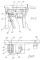
- a device adapted to stop the machine in case, for any reason, a variation of the ejecting device orientation takes place relative to the vertical plane.
- Said device comprises a tube shaped body (37) positioned at right angles relative to ejecting device upper cross member (38) which is hingedly connected, on the average at pivot axis (39), to base (40) of the carriage mention ed above.
- Said small ball is provided with an extention rod (44) projecting through a suitable opening in the base of tubular member (37) and contacting, at the end thereof, a small lever (45).
- the latter pivots at (46) and it is resiliently loaded through a coil spring or the like, or else by the plunger of a microswitch (47), and it is adapted to control said microswitch which is provided in turn to control the power supply to said geared motor assembly (33), or any other suitable driving means for carriage (20).
- any undesirable rotation of the ejecting device around axis (39) results in a pressure being applied on small ball (42) and thereby on small lever (45), whereby said carriage is stopped.
- Said ejecting device once it has unloaded a package of signatures starts a return stroke and in said conditions pivoting arm (23) is recalled upwards by electro-magnet (27) so that it does not interfere with forming package (14′).
- pivoted rotatable arm (23) might be replaced as well by an arm which is either able to move back through a telescoping arrangement, or to rotate on the vertical plane.
- an arrangement may also be provided whereby the whole ejecting carriage support frame can be moved back relative to the package forwarding direction.
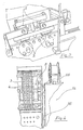
- the driving device for both pairs of chains (8) is driven by a gear motor unit whose rotating speed is controlled manually or in combination with the position of a vertical plane (48) provided at the location where the plurality of signatures move downwards.
- Said plane is hingedly supported at the top side thereof, at horizontal axis (49), and it is connected with naturally downward biased lever (50), provided in a position approximately at right angles relative to said plane.
- Said lever is in turn preferably provided with a projection forming a hooking point for the end of a spring (51) whose lower end is resiliently tied down to a suitable fastening member integral with the machine frame.
- Said lever is further provided with a projecting chute shaped portion, shown at (52), where an electronic sensor (53) is positioned, the latter sensing the longer or shorter distance from said projecting portion, which is of course related to the different lever positions.
- said lever tends to rise or to lower according to the higher or lower pressure of the pack of signatures on vertical plane (48), thereby increasing or decreasing, accordingly, the speed of said geared motor unit, through the sensor mentioned above.
- Said sensor may for instance comprise a voltage divider, suitably controlled by the oscillations of vertical plane (48).
- vertical plane (48) when the signatures are conveyed on platform (7), vertical plane (48), performing as a feeler, tends to move towards the machine rear side and in so doing it varies in the proper direction the speed of the forwarding chains mentioned above.
- the stroke length of the ejecting device supporting carriage is suitably adjustable, whereby a perfect ejection of the signatures is provided, for any different size thereof.
- Said signatures after having been ejected, land on the platform of a strap applying machine (54) known per se, where the packages are tied up by means of straps, webs, ropes and so on.
- said strap applying machine is connected, at the rear edge of the sides thereof, to the corresponding side of the subject machine, by means of hinged connections (55).
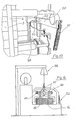
- said feature enables a suitable hoisting and transferring apparatus generally shown at (56), to be positioned directly in contact with said side-by-side paired machines, with a swinging arrangement, said apparatus being adapted to pick up signature packages from the strap applying machine and to load them on pallets or like means, according to need.
- said hoisting apparatus is provided with gravity actuated tongs (which are simple and cost effective concerning both construction and handling), carrying, on the pantograph arms thereof two adjustable levers (57), having rollers associated with one end thereof.
- Actuation of lever (58) may be performed also automatic strictlyally, by means of a pneumatic cylinder, an electro-magnet, or any other functionally equivalent device. Concerning the above it should be pointed out that, the heavier the package to be lifted, the stronger is the closure force.
- said handle (59) is advantageously provided both for actuating lever (58) and for displacing the tongs on the swinging hoist and for correctly laying the package on a pallet, on a platform, or anywhere it is desired.
- rollers (57) come to rest on said package, the pantograph levers slide outwards causing the tongs to open, lever (58) goes into engagement with the top portion of the L-shaped slot, and pin (60) integral with the pantograph lever, causes the automatic opening and keeps said tongs in the open position.
Landscapes
- Engineering & Computer Science (AREA)
- Mechanical Engineering (AREA)
- Pile Receivers (AREA)
- Auxiliary Devices For And Details Of Packaging Control (AREA)
- Packaging Of Special Articles (AREA)
- Feeding Of Articles By Means Other Than Belts Or Rollers (AREA)
- Intermediate Stations On Conveyors (AREA)
Applications Claiming Priority (2)
| Application Number | Priority Date | Filing Date | Title |
|---|---|---|---|
| IT2023988 | 1988-04-18 | ||
| IT20239/88A IT1217429B (it) | 1988-04-18 | 1988-04-18 | Macchina impilatrice di segnature,a funzionamento continuo,provvista di un apposito dispositivo per l'espulsione,in senso trasversale,del pacco formato |
Publications (3)
| Publication Number | Publication Date |
|---|---|
| EP0339002A2 true EP0339002A2 (de) | 1989-10-25 |
| EP0339002A3 EP0339002A3 (de) | 1991-01-30 |
| EP0339002B1 EP0339002B1 (de) | 1994-07-27 |
Family
ID=11165042
Family Applications (1)
| Application Number | Title | Priority Date | Filing Date |
|---|---|---|---|
| EP89830168A Expired - Lifetime EP0339002B1 (de) | 1988-04-18 | 1989-04-18 | Kontinuierlicher Signaturenpaketausleger, versehen mit einer speziellen Vorrichtung für die Querverschiebung des zusammengefassten Paketes |
Country Status (6)
| Country | Link |
|---|---|
| US (1) | US4977726A (de) |
| EP (1) | EP0339002B1 (de) |
| JP (1) | JPH02221058A (de) |
| DE (1) | DE68917001T2 (de) |
| ES (1) | ES2057176T3 (de) |
| IT (1) | IT1217429B (de) |
Cited By (2)
| Publication number | Priority date | Publication date | Assignee | Title |
|---|---|---|---|---|
| FR2741055A1 (fr) * | 1995-11-13 | 1997-05-16 | Realisations Etudes Et Commerc | Dispositif de regulation de la pression d'empilage pour un dispositif d'empilage horizontal de cahiers |
| EP1378472A1 (de) * | 2002-07-02 | 2004-01-07 | Müller Martini Holding AG | Einrichtung zum Transport eines in einer Zusammentragmaschine aus stehend aneinandergereihten Druckbogen gebildeten, auf einer Auflage liegenden Stapels |
Families Citing this family (1)
| Publication number | Priority date | Publication date | Assignee | Title |
|---|---|---|---|---|
| US5092236A (en) * | 1990-06-06 | 1992-03-03 | Quipp Systems, Inc. | Method and apparatus for stacking, aligning and compressing signatures |
Family Cites Families (14)
| Publication number | Priority date | Publication date | Assignee | Title |
|---|---|---|---|---|
| GB1073717A (en) * | 1963-06-28 | 1967-06-28 | Nederlanden Staat | Apparatus for stacking documents or flat articles |
| US3562775A (en) * | 1968-05-09 | 1971-02-09 | Crown Envelope Corp | Envelope boxing method and apparatus |
| US3772972A (en) * | 1972-03-20 | 1973-11-20 | Taylor M L | Stacker |
| US3865365A (en) * | 1973-08-17 | 1975-02-11 | Ibm | Apparatus and method for unloading mail stackers |
| US3887088A (en) * | 1974-03-18 | 1975-06-03 | Harris Intertype Corp | Method and apparatus for forming a vertical stack of signatures |
| US4172531A (en) * | 1975-12-29 | 1979-10-30 | Grapha-Holding Ag | Apparatus for transforming a stream of overlapping paper sheets into a staple of sheets |
| US4058226A (en) * | 1976-01-19 | 1977-11-15 | Box Innards, Inc. | High speed automatic stacker for partitions and the like |
| US4074508A (en) * | 1976-12-21 | 1978-02-21 | Riegel Textile Corporation | Apparatus for compressing and banding a predetermined number of articles |
| US4141193A (en) * | 1977-07-12 | 1979-02-27 | Joa Curt G | Horizontal diaper grouper |
| CH630860A5 (fr) * | 1979-05-18 | 1982-07-15 | Bobst Sa | Dispositif pour recevoir et empaqueter des boites pliantes confectionnees par une plieuse-colleuse. |
| CH663397A5 (de) * | 1984-05-11 | 1987-12-15 | Grapha Holding Ag | Stapeleinrichtung fuer druckbogen. |
| JPS6243963U (de) * | 1985-09-05 | 1987-03-17 | ||
| DE3641859A1 (de) * | 1986-12-08 | 1988-06-09 | Ficker Otto Ag | Verfahren zum automatischen verpacken von briefhuellen und versandtaschen in ein behaeltnis und verpackungsautomat insbesondere zum durchfuehren der verfahren |
| US4772003A (en) * | 1987-02-24 | 1988-09-20 | Dainihon Insatsu Kabushiki Kaisha | Apparatus for stacking signatures or the like |
-
1988
- 1988-04-18 IT IT20239/88A patent/IT1217429B/it active
-
1989
- 1989-04-05 US US07/334,091 patent/US4977726A/en not_active Expired - Fee Related
- 1989-04-18 DE DE68917001T patent/DE68917001T2/de not_active Expired - Fee Related
- 1989-04-18 ES ES89830168T patent/ES2057176T3/es not_active Expired - Lifetime
- 1989-04-18 JP JP1098628A patent/JPH02221058A/ja active Pending
- 1989-04-18 EP EP89830168A patent/EP0339002B1/de not_active Expired - Lifetime
Cited By (4)
| Publication number | Priority date | Publication date | Assignee | Title |
|---|---|---|---|---|
| FR2741055A1 (fr) * | 1995-11-13 | 1997-05-16 | Realisations Etudes Et Commerc | Dispositif de regulation de la pression d'empilage pour un dispositif d'empilage horizontal de cahiers |
| WO1997018152A1 (fr) * | 1995-11-13 | 1997-05-22 | Realisations, Etudes & Commercialisation De Matériel Pour L'industrie, Societe Anonyme | Dispositif de regulation de la pression d'empilage pour un dispositif d'empilage horizontal de cahiers |
| EP1378472A1 (de) * | 2002-07-02 | 2004-01-07 | Müller Martini Holding AG | Einrichtung zum Transport eines in einer Zusammentragmaschine aus stehend aneinandergereihten Druckbogen gebildeten, auf einer Auflage liegenden Stapels |
| US7168910B2 (en) | 2002-07-02 | 2007-01-30 | Muller Martini Holding Ag | Device for transporting a horizontal stack positioned on a support and formed in a gathering machine with upright, lined-up signatures |
Also Published As
| Publication number | Publication date |
|---|---|
| IT1217429B (it) | 1990-03-22 |
| EP0339002A3 (de) | 1991-01-30 |
| IT8820239A0 (it) | 1988-04-18 |
| JPH02221058A (ja) | 1990-09-04 |
| US4977726A (en) | 1990-12-18 |
| ES2057176T3 (es) | 1994-10-16 |
| DE68917001T2 (de) | 1994-11-10 |
| EP0339002B1 (de) | 1994-07-27 |
| DE68917001D1 (de) | 1994-09-01 |
Similar Documents
| Publication | Publication Date | Title |
|---|---|---|
| US4457658A (en) | Device for introducing a batch of sheets into a processing machine | |
| US4613268A (en) | Process and apparatus for the automatic supply of a machine for processing products in the form of sheets | |
| US5375967A (en) | Method and apparatus for palletizing and depalletizing | |
| US4538511A (en) | Signature handling apparatus | |
| US5460479A (en) | Signature stacking machine | |
| US6238173B1 (en) | Apparatus for placing groups of products on pallets | |
| US6129504A (en) | Method of palletizing sheet-like products using a stack grasper | |
| US4658715A (en) | System for automating the palletizing of bundles | |
| CN112027178A (zh) | 一种包装袋自动送料捆扎机 | |
| EP0525564B1 (de) | Einrichtung zum Zuführen von Stapeln von Zuschnitten an eine Verarbeitungsmaschine | |
| US4978117A (en) | Apparatus for conveying printing plates | |
| US4222311A (en) | Process and system for producing folded boxes | |
| US6267550B1 (en) | Container nesting and counting apparatus | |
| GB2265596A (en) | Valve bag handling apparatus | |
| EP0339002B1 (de) | Kontinuierlicher Signaturenpaketausleger, versehen mit einer speziellen Vorrichtung für die Querverschiebung des zusammengefassten Paketes | |
| JPH04361947A (ja) | 第1搬送路に沿って搬送されるずれ重なり形成体から製品を選択的に第2搬送路に移行する装置 | |
| US4396335A (en) | Arrangement for orderly placing of cross wound spools | |
| US5495700A (en) | Process and apparatus for processing printing products | |
| US6524058B1 (en) | Assembly and method for stacking, conveying and lifting lids | |
| CN212172682U (zh) | 一种码垛机 | |
| JPS6045099B2 (ja) | うろこ状に重なり合って連続的に供給される所定数の物品を群に分別する装置 | |
| US4442874A (en) | Automatic valve bag placer | |
| US5662454A (en) | Device for automatically filling a container for collecting flat objects | |
| JP2001522766A (ja) | シートセット給送装置 | |
| CN104321254B (zh) | 加工大量敞口袋的装置和方法 |
Legal Events
| Date | Code | Title | Description |
|---|---|---|---|
| PUAI | Public reference made under article 153(3) epc to a published international application that has entered the european phase |
Free format text: ORIGINAL CODE: 0009012 |
|
| AK | Designated contracting states |
Kind code of ref document: A2 Designated state(s): BE CH DE ES FR GB LI NL SE |
|
| PUAL | Search report despatched |
Free format text: ORIGINAL CODE: 0009013 |
|
| AK | Designated contracting states |
Kind code of ref document: A3 Designated state(s): BE CH DE ES FR GB LI NL SE |
|
| 17P | Request for examination filed |
Effective date: 19910415 |
|
| 17Q | First examination report despatched |
Effective date: 19921202 |
|
| GRAA | (expected) grant |
Free format text: ORIGINAL CODE: 0009210 |
|
| AK | Designated contracting states |
Kind code of ref document: B1 Designated state(s): BE CH DE ES FR GB LI NL SE |
|
| REF | Corresponds to: |
Ref document number: 68917001 Country of ref document: DE Date of ref document: 19940901 |
|
| ET | Fr: translation filed | ||
| REG | Reference to a national code |
Ref country code: ES Ref legal event code: FG2A Ref document number: 2057176 Country of ref document: ES Kind code of ref document: T3 |
|
| EAL | Se: european patent in force in sweden |
Ref document number: 89830168.4 |
|
| PLBE | No opposition filed within time limit |
Free format text: ORIGINAL CODE: 0009261 |
|
| STAA | Information on the status of an ep patent application or granted ep patent |
Free format text: STATUS: NO OPPOSITION FILED WITHIN TIME LIMIT |
|
| 26N | No opposition filed | ||
| PGFP | Annual fee paid to national office [announced via postgrant information from national office to epo] |
Ref country code: BE Payment date: 19960329 Year of fee payment: 8 |
|
| PGFP | Annual fee paid to national office [announced via postgrant information from national office to epo] |
Ref country code: GB Payment date: 19960409 Year of fee payment: 8 |
|
| PGFP | Annual fee paid to national office [announced via postgrant information from national office to epo] |
Ref country code: SE Payment date: 19960430 Year of fee payment: 8 Ref country code: NL Payment date: 19960430 Year of fee payment: 8 Ref country code: FR Payment date: 19960430 Year of fee payment: 8 |
|
| PGFP | Annual fee paid to national office [announced via postgrant information from national office to epo] |
Ref country code: CH Payment date: 19960513 Year of fee payment: 8 |
|
| PGFP | Annual fee paid to national office [announced via postgrant information from national office to epo] |
Ref country code: ES Payment date: 19960620 Year of fee payment: 8 |
|
| PGFP | Annual fee paid to national office [announced via postgrant information from national office to epo] |
Ref country code: DE Payment date: 19960626 Year of fee payment: 8 |
|
| PG25 | Lapsed in a contracting state [announced via postgrant information from national office to epo] |
Ref country code: GB Effective date: 19970418 |
|
| PG25 | Lapsed in a contracting state [announced via postgrant information from national office to epo] |
Ref country code: SE Effective date: 19970419 Ref country code: ES Free format text: LAPSE BECAUSE OF NON-PAYMENT OF DUE FEES Effective date: 19970419 |
|
| PG25 | Lapsed in a contracting state [announced via postgrant information from national office to epo] |
Ref country code: LI Free format text: LAPSE BECAUSE OF NON-PAYMENT OF DUE FEES Effective date: 19970430 Ref country code: CH Free format text: LAPSE BECAUSE OF NON-PAYMENT OF DUE FEES Effective date: 19970430 Ref country code: BE Effective date: 19970430 |
|
| BERE | Be: lapsed |
Owner name: O.M.G. DI GIORGIO PESSINA E ALDO PEROBELLI S.N.C Effective date: 19970430 |
|
| PG25 | Lapsed in a contracting state [announced via postgrant information from national office to epo] |
Ref country code: NL Effective date: 19971101 |
|
| GBPC | Gb: european patent ceased through non-payment of renewal fee |
Effective date: 19970418 |
|
| REG | Reference to a national code |
Ref country code: CH Ref legal event code: PL |
|
| PG25 | Lapsed in a contracting state [announced via postgrant information from national office to epo] |
Ref country code: FR Free format text: LAPSE BECAUSE OF NON-PAYMENT OF DUE FEES Effective date: 19971231 |
|
| PG25 | Lapsed in a contracting state [announced via postgrant information from national office to epo] |
Ref country code: DE Free format text: LAPSE BECAUSE OF NON-PAYMENT OF DUE FEES Effective date: 19980101 |
|
| NLV4 | Nl: lapsed or anulled due to non-payment of the annual fee |
Effective date: 19971101 |
|
| EUG | Se: european patent has lapsed |
Ref document number: 89830168.4 |
|
| REG | Reference to a national code |
Ref country code: FR Ref legal event code: ST |
|
| REG | Reference to a national code |
Ref country code: ES Ref legal event code: FD2A Effective date: 19990503 |