EP1378472A1 - Device for transporting a stack of juxtaposed printed sheets standing on edge, lying on a support - Google Patents
Device for transporting a stack of juxtaposed printed sheets standing on edge, lying on a support Download PDFInfo
- Publication number
- EP1378472A1 EP1378472A1 EP02405554A EP02405554A EP1378472A1 EP 1378472 A1 EP1378472 A1 EP 1378472A1 EP 02405554 A EP02405554 A EP 02405554A EP 02405554 A EP02405554 A EP 02405554A EP 1378472 A1 EP1378472 A1 EP 1378472A1
- Authority
- EP
- European Patent Office
- Prior art keywords
- stack
- support
- pliers
- movable
- designed
- Prior art date
- Legal status (The legal status is an assumption and is not a legal conclusion. Google has not performed a legal analysis and makes no representation as to the accuracy of the status listed.)
- Granted
Links
Images

Classifications
-
- B—PERFORMING OPERATIONS; TRANSPORTING
- B65—CONVEYING; PACKING; STORING; HANDLING THIN OR FILAMENTARY MATERIAL
- B65B—MACHINES, APPARATUS OR DEVICES FOR, OR METHODS OF, PACKAGING ARTICLES OR MATERIALS; UNPACKING
- B65B27/00—Bundling particular articles presenting special problems using string, wire, or narrow tape or band; Baling fibrous material, e.g. peat, not otherwise provided for
- B65B27/08—Bundling paper sheets, envelopes, bags, newspapers, or other thin flat articles
-
- B—PERFORMING OPERATIONS; TRANSPORTING
- B65—CONVEYING; PACKING; STORING; HANDLING THIN OR FILAMENTARY MATERIAL
- B65G—TRANSPORT OR STORAGE DEVICES, e.g. CONVEYORS FOR LOADING OR TIPPING, SHOP CONVEYOR SYSTEMS OR PNEUMATIC TUBE CONVEYORS
- B65G61/00—Use of pick-up or transfer devices or of manipulators for stacking or de-stacking articles not otherwise provided for
-
- B—PERFORMING OPERATIONS; TRANSPORTING
- B65—CONVEYING; PACKING; STORING; HANDLING THIN OR FILAMENTARY MATERIAL
- B65H—HANDLING THIN OR FILAMENTARY MATERIAL, e.g. SHEETS, WEBS, CABLES
- B65H31/00—Pile receivers
- B65H31/30—Arrangements for removing completed piles
- B65H31/3036—Arrangements for removing completed piles by gripping the pile
- B65H31/3045—Arrangements for removing completed piles by gripping the pile on the outermost articles of the pile for clamping the pile
-
- B—PERFORMING OPERATIONS; TRANSPORTING
- B65—CONVEYING; PACKING; STORING; HANDLING THIN OR FILAMENTARY MATERIAL
- B65H—HANDLING THIN OR FILAMENTARY MATERIAL, e.g. SHEETS, WEBS, CABLES
- B65H2301/00—Handling processes for sheets or webs
- B65H2301/30—Orientation, displacement, position of the handled material
- B65H2301/32—Orientation of handled material
- B65H2301/321—Standing on edge
-
- B—PERFORMING OPERATIONS; TRANSPORTING
- B65—CONVEYING; PACKING; STORING; HANDLING THIN OR FILAMENTARY MATERIAL
- B65H—HANDLING THIN OR FILAMENTARY MATERIAL, e.g. SHEETS, WEBS, CABLES
- B65H2301/00—Handling processes for sheets or webs
- B65H2301/40—Type of handling process
- B65H2301/42—Piling, depiling, handling piles
- B65H2301/422—Handling piles, sets or stacks of articles
- B65H2301/4224—Gripping piles, sets or stacks of articles
- B65H2301/42242—Gripping piles, sets or stacks of articles by acting on the outermost articles of the pile for clamping the pile
-
- Y—GENERAL TAGGING OF NEW TECHNOLOGICAL DEVELOPMENTS; GENERAL TAGGING OF CROSS-SECTIONAL TECHNOLOGIES SPANNING OVER SEVERAL SECTIONS OF THE IPC; TECHNICAL SUBJECTS COVERED BY FORMER USPC CROSS-REFERENCE ART COLLECTIONS [XRACs] AND DIGESTS
- Y10—TECHNICAL SUBJECTS COVERED BY FORMER USPC
- Y10S—TECHNICAL SUBJECTS COVERED BY FORMER USPC CROSS-REFERENCE ART COLLECTIONS [XRACs] AND DIGESTS
- Y10S414/00—Material or article handling
- Y10S414/10—Associated with forming or dispersing groups of intersupporting articles, e.g. stacking patterns
- Y10S414/12—Associated with forming or dispersing groups of intersupporting articles, e.g. stacking patterns including means pressing against top or end of group
Definitions
- the invention relates to a device for transporting a lying stack, which is formed in a collecting device from standing sheets arranged in a row, from a stack support to a clipboard.
- Devices of this type are used for the disposal of so-called bar booms according to EP 0 623 542 A1 and EP 1 199 275 A1.
- a known disposal of a boom 327 provides a brochure 327.889 MÜLLER MARTINI.
- the lying stack produced on the log boom from standing together printed sheets are brought together on a support or. collected, compressed and strapped. Then the finished rods resp. Stack manually, laterally shifted over a roller table from the support and then picked up by a crane and placed on pallets.
- the printed sheets which are brought together to form a loose stack, are pressed together at the conveying end of the stacking support and strapped and then gripped by a hoist outside the strapping station.
- This requires a pair of pliers for the pressing and strapping process in the bar boom as well as another pair of pliers for transporting the set stack to the clipboard.
- the object of the present invention is now a device to create the type mentioned above with which a multiple Effort can be avoided.
- this object is achieved in that above of the stack support, compressing the ends of the stack, vertically and horizontally movable pliers arranged which is a strapped stack from the stacking pad in the neighboring clipboard is transferred.
- This proposal allows an execution where the strapping of a stack on the stacking support as well as next to it is possible.
- the device according to the invention is suitable viewed in the conveying direction of the printed sheet on the left as well as to the right of the stacking support, so that a transport is possible on both sides.
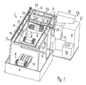
- a device 1 is illustrated, with which stacks 4 formed in a collating machine 2 from standing sheets 3 arranged in a row can be transported from a stack support 5 into an intermediate storage area 6, the sheets 3 being pressed together in this way perpendicular to the stacking direction and be strapped.
- the printed sheets 3, as disclosed in EP 1 199 275 A1 are fed in a shingled formation to the stacking support 5 via a deflection device 8 and placed in a row on a moving front support element 7 until a subsequent support element closes the stack 4 at the rear end.
- the loose stack 4 then reaches its end position on the stack support 5. This situation is illustrated by FIGS. 1 to 3.
- a movable pliers 10 is provided above the stack support 5, which presses the stack 4 at the ends and after lifting from the stack support 5 into an adjacent one Strapping station 11 offset, where it is encompassed by a band (not visible), is further transferred to a storage table 12 or to the clipboard 6.
- a pallet 13 on which the stacks 4 are placed next to and on top of one another. Further transport takes place with a pallet truck or forklift.
- a loadable vehicle could also be provided instead of one or more pallets 13.
- the pliers 10, which are formed from two clamping jaws 14, 15, are arranged so that they can be moved in a first conveying direction 7 from the stacking support 5 into the clipboard 6 by means of a bridge support 16 which is arranged on a support frame transversely to its longitudinal extent.
- the clipboard 6 can be designed as an automatic palletizing device.
- the tongs 10 are arranged on the bridge support 16 such that they can be moved transversely to the first conveying direction F.
- the pliers 10 are designed to be rotatable about a vertical axis.
- the bridge girder 16 has rollers (not shown) at the ends, which are continuously supported in lateral web girders 17, 18.
- the bridge girder 16 is connected to two rotating traction means 19, which are driven parallel to the first conveying direction F by an electric motor 20 fastened to the support frame 9.
- a common drive shaft 21 is provided, on each of which pulleys assigned to a traction means 19 are fastened, on which a toothed belt rotates.
- the clamping jaws 14, 15 of the pliers 10 are in turn fastened to an adjustable support 22 below the bridge support 16. That is, the carrier 22 is guided on vertical arms 23 which are fastened to the bridge carrier 16. The carrier 22 is raised and lowered by means of a winch-like elevator 24 which is fastened on the bridge carrier 16. The height of the pliers 10 is controlled by a rotary encoder and pulling straps 25 are provided as holding elements.
- the tongs 10 are actuated by a piston-cylinder unit 26 attached to the carrier 22. That is, the immovable clamping jaw 15 is aligned with the front end of the stack 4, so that the pliers 10 are only opened by a clamping jaw 14. However, this does not rule out that the position of the immovable clamping jaw 15 can be changed.
- the mode of operation of the device 1 alternatively allows the stack 4 on the stack support 5 to be gripped in different positions by the pliers 10 and placed in the clipboard 6 offset to the receiving position. It is therefore expedient if both clamping jaws 14, 15 of the pliers 10 can be driven, ie, for example, each clamping jaw 14, 15 is assigned a piston-cylinder unit which are actuated together. It is advantageous here if the clamping jaws 14, 15 are aligned approximately symmetrically on the stack 4 or that the position of the stack 4 is detected and the clamping jaw is then controlled.
- clamping jaws 14, 15 could pass through a rack and pinion gear attached to the carrier 22 is actuated be, for example, such that a between the jaws 14, 15 arranged gear on two opposite Racks acts, each with a jaw 14, 15th are connected.
- FIGS. 1 to 3 show, in a schematic arrangement of the device 1, a bar delivery device, referred to as a collecting device 2, to which a scaly stream 27 of printing sheets 3 are fed, which run into the bar delivery device from a printing machine (not visible) and over the opposite side a deflection device 8 can be turned. Following the deflection device 8, the shingled stream 27 flows into a stack support 5 on which a stack 4 of printed sheets 3 standing on the fold develops in the horizontal direction.
- FIGS. 1 and 2 show an imperfect stack 4, which has reached a board insertion station 28, through which the front and rear ends of a stack 4 are provided with an end board. With 29 a board magazine is noted in which boards are provided.
- exemplary embodiments can be found in EP 0 623 542 A1 and EP 1 199 275 A1.
- the present device 1 is constructed in such a way that it can be used as a fully automatic machine behind a printing press.
Abstract
Description
Die Erfindung betrifft eine Einrichtung zum Transport eines in
einer Sammelvorrichtung aus stehend aneinandergereihten Druckbogen
gebildeten, liegenden Stapels, von einer Stapelauflage
in eine Zwischenablage.
Einrichtungen dieser Art werden zur Entsorgung von sog. Stangenauslegern
gemäss EP 0 623 542 A1 und EP 1 199 275 A1 verwendet.
Eine bekannte Entsorgung eines Stangenauslegers 327 vermittelt
ein Prospekt 327.889 MÜLLER MARTINI. Die auf dem Stangenausleger
produzierten liegenden Stapel aus stehend aneinandergereihten
Druckbogen werden auf einer Auflage zusammengetragen
resp. gesammelt, zusammengepresst und umreift. Danach werden
die fertigen Stangen resp. Stapel manuell, seitlich über einen
Rollentisch von der Auflage verschoben und anschliessend von
einem Kran erfasst und auf Paletten abgesetzt. The invention relates to a device for transporting a lying stack, which is formed in a collecting device from standing sheets arranged in a row, from a stack support to a clipboard.
Devices of this type are used for the disposal of so-called bar booms according to EP 0 623 542 A1 and EP 1 199 275 A1.
A known disposal of a boom 327 provides a brochure 327.889 MÜLLER MARTINI. The lying stack produced on the log boom from standing together printed sheets are brought together on a support or. collected, compressed and strapped. Then the finished rods resp. Stack manually, laterally shifted over a roller table from the support and then picked up by a crane and placed on pallets.
Im gleichen Prospekt ist auch eine Ausführung dargestellt, bei der im Anschluss an einen Rollentisch ein Palettierautomat angeordnet ist.In the same brochure, an embodiment is shown, at which arranged a palletizing machine following a roller table is.
Bei diesen Anlagen werden die zu einem losen Stapel zusammengetragenen
Druckbogen am Förderende der Stapelauflage zusammengepresst
sowie umreift und danach von einem Hebezeug ausserhalb
der Umreifungsstation erfasst.
Dies bedingt sowohl eine Zange für den Press- und Umreifungsvorgang
im Stangenausleger wie auch eine weitere Zange für den
Transport des abgebundenen Stapels in die Zwischenablage.In these systems, the printed sheets, which are brought together to form a loose stack, are pressed together at the conveying end of the stacking support and strapped and then gripped by a hoist outside the strapping station.
This requires a pair of pliers for the pressing and strapping process in the bar boom as well as another pair of pliers for transporting the set stack to the clipboard.
Aufgabe der vorliegenden Erfindung ist es nun, eine Einrichtung der eingangs genannten Art zu schaffen, mit der ein mehrfacher Aufwand vermieden werden kann.The object of the present invention is now a device to create the type mentioned above with which a multiple Effort can be avoided.
Erfindungsgemäss wird diese Aufgabe dadurch gelöst, dass oberhalb der Stapelauflage eine den Stapel an den Enden zusammenpressende, senkrecht und horizontal verfahrbare Zange angeordnet ist, die einen umreiften Stapel von der Stapelauflage in die benachbarte Zwischenablage überführt.According to the invention, this object is achieved in that above of the stack support, compressing the ends of the stack, vertically and horizontally movable pliers arranged which is a strapped stack from the stacking pad in the neighboring clipboard is transferred.
Dieser Vorschlag gestattet eine Ausführung, bei der die Umreifung eines Stapels auf der Stapelauflage wie auch neben dieser möglich ist.This proposal allows an execution where the strapping of a stack on the stacking support as well as next to it is possible.
Selbstverständlich eignet sich die erfindungsgemässe Einrichtung in Förderrichtung der Druckbogen betrachtet sowohl links wie auch rechts von der Stapelauflage, sodass ein Transport nach beiden Seiten möglich ist. Of course, the device according to the invention is suitable viewed in the conveying direction of the printed sheet on the left as well as to the right of the stacking support, so that a transport is possible on both sides.
Die erfindungsgemässe Einrichtung kann rechnergesteuert -ohne Bedienungspersonen- den Transport der Stapel von der Stapelauflage zu der Zwischenablage automatisch durchführen. Anschliessend wird die Erfindung mit Bezugnahme auf die Zeichnung, auf die bezüglich aller in der Beschreibung nicht näher erwähnten Einzelheiten verwiesen wird, anhand eines Ausführungsbeispiels erläutert. Es zeigen in der Zeichnung:
- Fig. 1
- eine räumliche Darstellung der erfindungsgemässen Einrichtung,
- Fig. 2
- eine Seitenansicht der in Fig. 1 dargestellten Einrichtung und
- Fig. 3
- einen Grundriss der in Fig. 2 gezeigten Einrichtung.
- Fig. 1
- a spatial representation of the device according to the invention,
- Fig. 2
- a side view of the device shown in Fig. 1 and
- Fig. 3
- a floor plan of the device shown in Fig. 2.
In den Fig. 1 bis 3 ist eine Einrichtung 1 veranschaulicht,
mit welcher in einer Zusammentragmaschine 2 aus stehend aneinandergereihten
Druckbogen 3 gebildete Stapel 4 von einer Stapelauflage
5 in eine Zwischenablage 6 transportierbar sind,
wobei die Druckbogen 3 auf diesem Weg senkrecht zur Stapelbildungsrichtung
zusammengepresst und umreift werden.
Zuvor werden die Druckbogen 3 wie in der EP 1 199 275 A1 offenbart
in geschuppter Formation über eine Umlenkvorrichtung 8
der Stapelauflage 5 zugeführt und an einem sich fortbewegenden
vorderen Stützelement 7 aneinandergereiht aufgestellt, bis ein
folgendes Stützelement den Stapel 4 an dem hinteren Ende abschliesst.
Danach erreicht der lose Stapel 4 seine Endposition
auf der Stapelauflage 5. Diese Situation wird durch die Fig. 1
bis 3 vermittelt. 1 to 3, a device 1 is illustrated, with which
Prior to this, the printed
Zur Ueberführung des Stapels 4, der schon auf der Stapelauflage
5 umreift werden könnte, ist oberhalb der Stapelauflage 5
eine an einem Traggestell 9 verfahrbare Zange 10 vorgesehen,
die den Stapel 4 an den Enden zusammenpresst und nach dem Anheben
von der Stapelauflage 5 in eine benachbarte Umreifungsstation
11 versetzt, wo er von einem Band (nicht ersichtlich)
umfasst weiter auf einen Ablagetische 12 oder in die Zwischenablage
6 versetzt wird. In der Zwischenablage 6 steht eine Palette
13 bereit, auf der die Stapel 4 neben- und übereinander
abgelegt werden. Der Weitertransport erfolgt mit einem Hubwagen
oder -stapler. Selbstverständlich könnte anstelle einer
oder mehrerer Paletten 13 auch ein beladbares Fahrzeug beigestellt
werden. Die aus zwei Klemmbacken 14, 15 gebildete Zange
10 ist mittels Brückenträger 16, der an einem Traggestell quer
zu seiner Längserstreckungen in einer ersten Förderrichtung 7
von der Stapelauflage 5 in die Zwischenablage 6 verfahrbar angeordnet.
Wie schon bemerkt, kann die Zwischenablage 6 als Palettierautomat
ausgebildet sein. Deshalb ist die Zange 10 quer
zur ersten Förderrichtung F verfahrbar an dem Brückenträger 16
angeordnet.
Um eine kreuzweise Lagerung der Stapel 4 in der Zwischenablage
6 vorsehen zu können, ist die Zange 10 um eine senkrechte Achse
drehbar ausgebildet.
Der Brückenträger 16 weist an den Enden Laufrollen (nicht dargestellt)
auf, die in seitlichen Bahnträgern 17, 18 laufend
gelagert sind. Der Brückenträger 16 ist mit zwei umlaufenden
Zugmitteln 19 verbunden, die parallel zur ersten Förderrichtung
F von einem am Traggestell 9 befestigten Elektromotor 20
angetrieben sind. Zur Uebertragung einer gleichmässigen Drehbewegung
auf beide Zugmittel 19 ist eine gemeinsame Antriebswelle
21 vorgesehen, an der jeweils einem Zugmittel 19 zugeordnete
Pulleys befestigt sind, an denen ein Zahnriemen umläuft.To transfer the
In order to be able to provide a crosswise storage of the
The
Die Klemmbacken 14, 15 der Zange 10 wiederum sind an einem unterhalb
des Brückenträgers 16 höhenverstellbaren Trägern 22
verstellbar befestigt. D.h. der Träger 22 ist an senkrechten
Auslegern 23, die an dem Brückenträger 16 befestigt sind, geführt.
Das Anheben und Absenken des Trägers 22 erfolgt mittels
einem windenähnlichen Aufzug 24, der auf dem Brückenträger 16
befestigt ist. Die Steuerung der Höhe der Zange 10 erfolgt
durch einen Drehgeber und als Halteelemente sind Zugbänder 25
vorgesehen.
Die Zange 10 wird durch eine am Träger 22 befestigte Kolben-Zylinder-Einheit
26 betätigt. D.h., die unbewegliche Klemmbacke
15 ist auf das vordere Ende des Stapels 4 ausgerichtet,
sodass die Zange 10 nurmehr durch eine Klemmbacke 14 geöffnet
wird. Dies schliesst jedoch nicht aus, dass die Position der
unbeweglichen Klemmbacke 15 verändert werden kann.
Die Funktionsweise der Einrichtung 1 erlaubt es alternativ,
dass der Stapel 4 auf der Stapelauflage 5 in unterschiedlichen
Position von der Zange 10 erfasst werden kann und in der Zwischenablage
6 versetzt zur Aufnahmeposition abgesetzt wird.
Somit ist es zweckmässig, wenn beide Klemmbacken 14, 15 der
Zange 10 antreibbar sind, d.h. jeder Klemmbacke 14, 15 ist
beispielsweise eine Kolben-Zylinder-Einheit zugeordnet, die
gemeinsam betätigt werden. Hierbei ist es vorteilhaft, wenn
die Klemmbacken 14, 15 etwa symmetrisch auf den Stapel 4 ausgerichtet
werden oder dass die Lage des Stapels 4 detektiert
wird und die Klemmbacke danach gesteuert werden. The
The
The mode of operation of the device 1 alternatively allows the
Als weitere Möglichkeit könnten die Klemmbacken 14, 15 durch
ein an dem Träger 22 befestigtes Zahnstangengetriebe betätigt
werden, beispielsweise so, dass ein zwischen den Klemmbacken
14, 15 angeordnetes Zahnrad auf zwei sich gegenüberliegende
Zahnstangen einwirkt, die mit jeweils einer Klemmbacke 14, 15
verbunden sind.As a further possibility, the
Des weiteren zeigen die Figuren 1 bis 3 in schematischer Anordnungsweise
zur Einrichtung 1 einen als Sammelvorrichtung 2
bezeichneten Stangenausleger, dem unterschlächtig ein Schuppemstrom
27 aus Druckbogen 3 zugeführt werden, die von einer
Druckmaschine (nicht ersichtlich) in den Stangenausleger einlaufen
und an der gegenüberliegenden Seite über eine Umlenkvorrichtung
8 gewendet werden. Im Anschluss an die Umlenkvorrichtung
8 mündet der gewendete Schuppenstrom 27 in eine Stapelauflage
5, auf der sich ein Stapel 4 aus auf dem Falz stehenden
Druckbogen 3 in horizontaler Richtung entwickelt. Die
Figuren 1 und 2 zeigen an dieser Stelle einen unvollkommenen
Stapel 4, der eine Brettereinschubstation 28 erreicht hat,
durch welche das vordere und hintere Ende eines Stapels 4 mit
einem Abschlussbrett versehen wird. Mit 29 ist ein Brettermagazin
vermerkt, in welchem Bretter bereitgestellt sind.
Wie schon eingangs erwähnt können Ausführungsbeispiele den EP
0 623 542 A1 und EP 1 199 275 A1 entnommen werden.
Die vorliegende Einrichtung 1 ist derart konstruiert, dass sie
als Vollautomat hinter einer Druckmaschine einsetzbar ist.Furthermore, FIGS. 1 to 3 show, in a schematic arrangement of the device 1, a bar delivery device, referred to as a
As already mentioned at the beginning, exemplary embodiments can be found in EP 0 623 542 A1 and EP 1 199 275 A1.
The present device 1 is constructed in such a way that it can be used as a fully automatic machine behind a printing press.
Claims (14)
Priority Applications (4)
| Application Number | Priority Date | Filing Date | Title |
|---|---|---|---|
| DE50211920T DE50211920D1 (en) | 2002-07-02 | 2002-07-02 | Means for transporting a stack formed in a gathering machine standing upright from one another, lying on a support stack |
| EP02405554A EP1378472B1 (en) | 2002-07-02 | 2002-07-02 | Device for transporting a stack of juxtaposed printed sheets standing on edge, lying on a support |
| JP2003270231A JP4523247B2 (en) | 2002-07-02 | 2003-07-01 | Apparatus for transporting a stack formed from printing papers arranged so as to stand adjacent to each other in a collating machine and placed on a placing table |
| US10/609,372 US7168910B2 (en) | 2002-07-02 | 2003-07-01 | Device for transporting a horizontal stack positioned on a support and formed in a gathering machine with upright, lined-up signatures |
Applications Claiming Priority (1)
| Application Number | Priority Date | Filing Date | Title |
|---|---|---|---|
| EP02405554A EP1378472B1 (en) | 2002-07-02 | 2002-07-02 | Device for transporting a stack of juxtaposed printed sheets standing on edge, lying on a support |
Publications (2)
| Publication Number | Publication Date |
|---|---|
| EP1378472A1 true EP1378472A1 (en) | 2004-01-07 |
| EP1378472B1 EP1378472B1 (en) | 2008-03-19 |
Family
ID=29719807
Family Applications (1)
| Application Number | Title | Priority Date | Filing Date |
|---|---|---|---|
| EP02405554A Expired - Lifetime EP1378472B1 (en) | 2002-07-02 | 2002-07-02 | Device for transporting a stack of juxtaposed printed sheets standing on edge, lying on a support |
Country Status (4)
| Country | Link |
|---|---|
| US (1) | US7168910B2 (en) |
| EP (1) | EP1378472B1 (en) |
| JP (1) | JP4523247B2 (en) |
| DE (1) | DE50211920D1 (en) |
Cited By (5)
| Publication number | Priority date | Publication date | Assignee | Title |
|---|---|---|---|---|
| DE102004009584A1 (en) * | 2004-02-25 | 2005-09-15 | Focke & Co.(Gmbh & Co. Kg) | Device for producing and palletizing carton packs |
| EP1790603A1 (en) | 2005-11-23 | 2007-05-30 | Müller Martini Holding AG | Method and device for intermediate storage of stacks |
| EP1816098A1 (en) | 2006-02-02 | 2007-08-08 | Müller Martini Holding AG | Method and device for forming stacks |
| EP2147877A1 (en) | 2008-07-24 | 2010-01-27 | Ferag AG | Paletting device and processing system with such a device |
| CN102689704A (en) * | 2011-03-22 | 2012-09-26 | 株式会社东芝 | Accumulating and strapping apparatus |
Families Citing this family (11)
| Publication number | Priority date | Publication date | Assignee | Title |
|---|---|---|---|---|
| US8000837B2 (en) | 2004-10-05 | 2011-08-16 | J&L Group International, Llc | Programmable load forming system, components thereof, and methods of use |
| US9650215B2 (en) | 2013-05-17 | 2017-05-16 | Intelligrated Headquarters Llc | Robotic carton unloader |
| EP2996973B1 (en) | 2013-05-17 | 2019-01-30 | Intelligrated Headquarters LLC | Robotic carton unloader |
| US9487361B2 (en) | 2013-05-17 | 2016-11-08 | Intelligrated Headquarters Llc | Robotic carton unloader |
| WO2015017444A1 (en) | 2013-07-30 | 2015-02-05 | Intelligrated Headquarters Llc | Robotic carton unloader |
| CN108584471B (en) | 2013-08-28 | 2020-05-29 | 因特利格兰特总部有限责任公司 | Robot carton unloader |
| US9623569B2 (en) | 2014-03-31 | 2017-04-18 | Intelligrated Headquarters, Llc | Autonomous truck loader and unloader |
| US10518916B2 (en) * | 2016-05-27 | 2019-12-31 | Daniel S. Underwood | Material processing system |
| DE112017004070B4 (en) | 2016-09-14 | 2022-04-28 | Intelligrated Headquarters, Llc | ROBOT CARTON UNLOADER |
| US10597235B2 (en) | 2016-10-20 | 2020-03-24 | Intelligrated Headquarters, Llc | Carton unloader tool for jam recovery |
| CN108190143A (en) * | 2018-03-09 | 2018-06-22 | 崔浩轩 | A kind of printing paper producing apparatus output collection device |
Citations (5)
| Publication number | Priority date | Publication date | Assignee | Title |
|---|---|---|---|---|
| US4419035A (en) * | 1982-04-21 | 1983-12-06 | Stobb, Inc. | Method and apparatus for moving bundles of sheets |
| US4674934A (en) * | 1984-05-11 | 1987-06-23 | Grapha-Holding Ag | Apparatus for stacking paper sheets and the like |
| EP0339002A2 (en) * | 1988-04-18 | 1989-10-25 | O.M.G. di GIORGIO PESSINA E ALDO PEROBELLI S.n.c. | Continuous signature stacker machine provided with a special device for transversely ejecting the assembled package |
| EP0623542A1 (en) * | 1993-05-07 | 1994-11-09 | Grapha-Holding Ag | Device for forming a stack of printed sheets, where these are piled on the edge |
| JPH08113210A (en) * | 1994-10-07 | 1996-05-07 | Dainippon Printing Co Ltd | Binding machine |
Family Cites Families (22)
| Publication number | Priority date | Publication date | Assignee | Title |
|---|---|---|---|---|
| US3076673A (en) * | 1962-01-16 | 1963-02-05 | Cullen Friestedt Company | Lifter mechanism with horizontally extensible jaw-supporting arms |
| JPS5213132B2 (en) * | 1972-02-05 | 1977-04-12 | ||
| DE2532297C3 (en) * | 1975-07-18 | 1981-02-12 | Gruner + Jahr Ag & Co, 2210 Itzehoe | Arrangement for storing and transporting the printed products led out of a printing machine in stack form |
| US4519740A (en) * | 1983-06-17 | 1985-05-28 | Stobb, Inc. | Apparatus and method for palletizing bundles of sheets |
| US4591198A (en) * | 1984-02-16 | 1986-05-27 | Monforte Robotics, Inc. | Robotic end effectors |
| JPS60180223U (en) * | 1984-05-11 | 1985-11-29 | 喜多 将夫 | Transfer device for conveyed objects |
| US4671934A (en) * | 1986-04-18 | 1987-06-09 | Buckman Laboratories, Inc. | Aminophosphonic acid/phosphate mixtures for controlling corrosion of metal and inhibiting calcium phosphate precipitation |
| US4658715A (en) * | 1986-04-14 | 1987-04-21 | Stobb Inc. | System for automating the palletizing of bundles |
| GB8709851D0 (en) * | 1987-04-25 | 1987-05-28 | Langston Machine | Stacking boxes of corrugated board |
| US5098254A (en) * | 1988-09-12 | 1992-03-24 | Fmc Corporation | Proximity detection means on a palletizer hand assembly |
| DE3835032A1 (en) * | 1988-10-14 | 1990-04-19 | Niepmann Traylift Transport | METHOD AND DEVICE FOR THE STACKING OF BLOCKS IN BLOCKS ON PALLETS STACKED |
| ES2030299T3 (en) * | 1988-12-31 | 1992-10-16 | System Gmbh | ROBOT PALLETIZER. |
| JPH02193818A (en) * | 1989-01-23 | 1990-07-31 | Okura Yusoki Co Ltd | Pallet loading system |
| JPH02193819A (en) * | 1989-01-23 | 1990-07-31 | Okura Yusoki Co Ltd | Commodity holding device |
| IT1252449B (en) * | 1991-07-22 | 1995-06-16 | Gd Spa | PROCEDURE AND DEVICE FOR ORDERING STACKS OF BLINDS IN A PACKAGING MACHINE |
| DE69100158T2 (en) * | 1991-09-02 | 1994-02-10 | Tabac Fab Reunies Sa | Gripping and transfer pliers. |
| IT1256310B (en) * | 1992-11-11 | 1995-11-30 | Ocme | DEVICE FOR THE COLLECTION, HANDLING AND DEPOSITION OF A STACK OF DIE CUTS |
| IT1263434B (en) * | 1993-06-16 | 1996-08-05 | Gd Spa | COLLECTION UNIT AND FEEDING OF STACKED STACKS |
| US5674049A (en) * | 1994-06-17 | 1997-10-07 | Automatic Handling, Inc. | Roll handling apparatus |
| EP0995555A1 (en) * | 1998-10-15 | 2000-04-26 | Tecan AG | Robot arm |
| US6315516B1 (en) * | 1998-10-19 | 2001-11-13 | Lemo Maschinenbau Gmbh | Device for delivering stackable bag packages, particularly plastic bags with a bottom fold |
| EP1199275B1 (en) | 2000-10-20 | 2004-07-14 | Grapha-Holding AG | Device for making a stack of printed sheets arranged side by side |
-
2002
- 2002-07-02 EP EP02405554A patent/EP1378472B1/en not_active Expired - Lifetime
- 2002-07-02 DE DE50211920T patent/DE50211920D1/en not_active Expired - Lifetime
-
2003
- 2003-07-01 US US10/609,372 patent/US7168910B2/en not_active Expired - Fee Related
- 2003-07-01 JP JP2003270231A patent/JP4523247B2/en not_active Expired - Fee Related
Patent Citations (5)
| Publication number | Priority date | Publication date | Assignee | Title |
|---|---|---|---|---|
| US4419035A (en) * | 1982-04-21 | 1983-12-06 | Stobb, Inc. | Method and apparatus for moving bundles of sheets |
| US4674934A (en) * | 1984-05-11 | 1987-06-23 | Grapha-Holding Ag | Apparatus for stacking paper sheets and the like |
| EP0339002A2 (en) * | 1988-04-18 | 1989-10-25 | O.M.G. di GIORGIO PESSINA E ALDO PEROBELLI S.n.c. | Continuous signature stacker machine provided with a special device for transversely ejecting the assembled package |
| EP0623542A1 (en) * | 1993-05-07 | 1994-11-09 | Grapha-Holding Ag | Device for forming a stack of printed sheets, where these are piled on the edge |
| JPH08113210A (en) * | 1994-10-07 | 1996-05-07 | Dainippon Printing Co Ltd | Binding machine |
Non-Patent Citations (1)
| Title |
|---|
| PATENT ABSTRACTS OF JAPAN vol. 1996, no. 09 30 September 1996 (1996-09-30) * |
Cited By (10)
| Publication number | Priority date | Publication date | Assignee | Title |
|---|---|---|---|---|
| DE102004009584A1 (en) * | 2004-02-25 | 2005-09-15 | Focke & Co.(Gmbh & Co. Kg) | Device for producing and palletizing carton packs |
| US7596926B2 (en) | 2004-02-25 | 2009-10-06 | Focke & Co. (Gmbh & Co. Kg) | Device for producing and palleting packaging boxes |
| EP1790603A1 (en) | 2005-11-23 | 2007-05-30 | Müller Martini Holding AG | Method and device for intermediate storage of stacks |
| EP1816098A1 (en) | 2006-02-02 | 2007-08-08 | Müller Martini Holding AG | Method and device for forming stacks |
| US7862020B2 (en) | 2006-02-02 | 2011-01-04 | Mueller Martini Holding Ag | Method for forming stacks from upright positioned, successively lined up signatures and arrangement for realizing the method |
| EP2147877A1 (en) | 2008-07-24 | 2010-01-27 | Ferag AG | Paletting device and processing system with such a device |
| CN102689704A (en) * | 2011-03-22 | 2012-09-26 | 株式会社东芝 | Accumulating and strapping apparatus |
| US8746135B2 (en) | 2011-03-22 | 2014-06-10 | Kabushiki Kaisha Toshiba | Accumulating and strapping apparatus |
| US8925448B2 (en) | 2011-03-22 | 2015-01-06 | Kabushiki Kaisha Toshiba | Accumulating and strapping apparatus |
| CN102689704B (en) * | 2011-03-22 | 2015-07-01 | 株式会社东芝 | Accumulating and strapping apparatus |
Also Published As
| Publication number | Publication date |
|---|---|
| US7168910B2 (en) | 2007-01-30 |
| JP4523247B2 (en) | 2010-08-11 |
| EP1378472B1 (en) | 2008-03-19 |
| US20040096309A1 (en) | 2004-05-20 |
| DE50211920D1 (en) | 2008-04-30 |
| JP2004035268A (en) | 2004-02-05 |
Similar Documents
| Publication | Publication Date | Title |
|---|---|---|
| EP1378472B1 (en) | Device for transporting a stack of juxtaposed printed sheets standing on edge, lying on a support | |
| EP0623542B1 (en) | Device for forming a stack of printed sheets, where these are piled on the edge | |
| CH671566A5 (en) | ||
| DE3314204A1 (en) | METHOD AND DEVICE FOR MOVING BUNCHS FORMED FROM ARC | |
| DE4203118C2 (en) | Device for gripping and transporting stacks of flat objects | |
| DE10022272B4 (en) | Device for palletizing packages | |
| DE10356563A1 (en) | Palleting device for cardboard sheet stacks has reception surface at reception station provided with vertically displaced support pins lifting cardboard sheet stacks for insertion of handling robot grippers | |
| DE2508745C2 (en) | Device for accumulating individually by means of a transport device fed paper sheets into stacks and for further transporting these stacks | |
| DE3414996C1 (en) | Device for pushing away stacks or packages deposited on a carrying device | |
| DE3540203C2 (en) | Device for conveying stacks of paper | |
| EP1405809A1 (en) | Device for forming parcels of stacked products | |
| EP0097308B1 (en) | Device for and method of palletizing bundled stacks of newspapers or the like | |
| EP1491477A1 (en) | Device for forming stacks | |
| DE2707191A1 (en) | DEVICE AND METHOD FOR HANDLING STRAPS FORMED FROM SHEETS, IN PARTICULAR IN THE GRAPHICAL INDUSTRY | |
| EP1611039A1 (en) | Transport device, in particular for panel-type workpieces | |
| DE4236362A1 (en) | Discharge mechanism for bookbinding sticking machine - has deposition device, following transverse stacking conveyor taking over book block(s) | |
| DE102009040792A1 (en) | Pallet stack manipulator for unstacking device for scheduling pallet stack with pallets nested with each other for unstacking, has centering device to center two pallets of pallet stack to each other | |
| EP0210172B1 (en) | Device for stacking thin-walled parts | |
| EP0875473B1 (en) | Apparatus for the stacking of single panels or packets of panels | |
| EP0691295B1 (en) | Plate feeding device for plate dividing saws | |
| DE2311871C3 (en) | Device for the aligned laying out of rows of pallets | |
| DE2220846A1 (en) | METHOD AND DEVICE FOR DISASSEMBLING STACKS OF BRICKS | |
| DE2557178B2 (en) | Stacking device for roof tiles | |
| EP0679534A1 (en) | Delivery device for signature stitching machine | |
| DE19507387A1 (en) | Handling system for assembling sheets of glass into packages |
Legal Events
| Date | Code | Title | Description |
|---|---|---|---|
| PUAI | Public reference made under article 153(3) epc to a published international application that has entered the european phase |
Free format text: ORIGINAL CODE: 0009012 |
|
| AK | Designated contracting states |
Kind code of ref document: A1 Designated state(s): AT BE BG CH CY CZ DE DK EE ES FI FR GB GR IE IT LI LU MC NL PT SE SK TR |
|
| AX | Request for extension of the european patent |
Extension state: AL LT LV MK RO SI |
|
| 17P | Request for examination filed |
Effective date: 20040517 |
|
| AKX | Designation fees paid |
Designated state(s): CH DE FR GB IT LI |
|
| RBV | Designated contracting states (corrected) |
Designated state(s): CH DE FR GB IT LI SE |
|
| GRAP | Despatch of communication of intention to grant a patent |
Free format text: ORIGINAL CODE: EPIDOSNIGR1 |
|
| GRAS | Grant fee paid |
Free format text: ORIGINAL CODE: EPIDOSNIGR3 |
|
| GRAA | (expected) grant |
Free format text: ORIGINAL CODE: 0009210 |
|
| AK | Designated contracting states |
Kind code of ref document: B1 Designated state(s): CH DE FR GB IT LI SE |
|
| REG | Reference to a national code |
Ref country code: GB Ref legal event code: FG4D Free format text: NOT ENGLISH |
|
| REG | Reference to a national code |
Ref country code: CH Ref legal event code: EP |
|
| REF | Corresponds to: |
Ref document number: 50211920 Country of ref document: DE Date of ref document: 20080430 Kind code of ref document: P |
|
| REG | Reference to a national code |
Ref country code: SE Ref legal event code: TRGR |
|
| ET | Fr: translation filed | ||
| PLBE | No opposition filed within time limit |
Free format text: ORIGINAL CODE: 0009261 |
|
| STAA | Information on the status of an ep patent application or granted ep patent |
Free format text: STATUS: NO OPPOSITION FILED WITHIN TIME LIMIT |
|
| 26N | No opposition filed |
Effective date: 20081222 |
|
| REG | Reference to a national code |
Ref country code: FR Ref legal event code: PLFP Year of fee payment: 14 |
|
| PGFP | Annual fee paid to national office [announced via postgrant information from national office to epo] |
Ref country code: DE Payment date: 20150715 Year of fee payment: 14 Ref country code: GB Payment date: 20150723 Year of fee payment: 14 |
|
| PGFP | Annual fee paid to national office [announced via postgrant information from national office to epo] |
Ref country code: FR Payment date: 20150727 Year of fee payment: 14 Ref country code: SE Payment date: 20150723 Year of fee payment: 14 |
|
| PGFP | Annual fee paid to national office [announced via postgrant information from national office to epo] |
Ref country code: IT Payment date: 20150731 Year of fee payment: 14 |
|
| PGFP | Annual fee paid to national office [announced via postgrant information from national office to epo] |
Ref country code: CH Payment date: 20151021 Year of fee payment: 14 |
|
| REG | Reference to a national code |
Ref country code: DE Ref legal event code: R119 Ref document number: 50211920 Country of ref document: DE |
|
| REG | Reference to a national code |
Ref country code: CH Ref legal event code: PL |
|
| REG | Reference to a national code |
Ref country code: SE Ref legal event code: EUG |
|
| GBPC | Gb: european patent ceased through non-payment of renewal fee |
Effective date: 20160702 |
|
| PG25 | Lapsed in a contracting state [announced via postgrant information from national office to epo] |
Ref country code: SE Free format text: LAPSE BECAUSE OF NON-PAYMENT OF DUE FEES Effective date: 20160703 Ref country code: FR Free format text: LAPSE BECAUSE OF NON-PAYMENT OF DUE FEES Effective date: 20160801 Ref country code: DE Free format text: LAPSE BECAUSE OF NON-PAYMENT OF DUE FEES Effective date: 20170201 Ref country code: LI Free format text: LAPSE BECAUSE OF NON-PAYMENT OF DUE FEES Effective date: 20160731 Ref country code: CH Free format text: LAPSE BECAUSE OF NON-PAYMENT OF DUE FEES Effective date: 20160731 |
|
| REG | Reference to a national code |
Ref country code: FR Ref legal event code: ST Effective date: 20170331 |
|
| PG25 | Lapsed in a contracting state [announced via postgrant information from national office to epo] |
Ref country code: GB Free format text: LAPSE BECAUSE OF NON-PAYMENT OF DUE FEES Effective date: 20160702 |
|
| PG25 | Lapsed in a contracting state [announced via postgrant information from national office to epo] |
Ref country code: IT Free format text: LAPSE BECAUSE OF NON-PAYMENT OF DUE FEES Effective date: 20160702 |