EP1405809A1 - Device for forming parcels of stacked products - Google Patents
Device for forming parcels of stacked products Download PDFInfo
- Publication number
- EP1405809A1 EP1405809A1 EP02405851A EP02405851A EP1405809A1 EP 1405809 A1 EP1405809 A1 EP 1405809A1 EP 02405851 A EP02405851 A EP 02405851A EP 02405851 A EP02405851 A EP 02405851A EP 1405809 A1 EP1405809 A1 EP 1405809A1
- Authority
- EP
- European Patent Office
- Prior art keywords
- stack
- support
- stacking
- package
- support element
- Prior art date
- Legal status (The legal status is an assumption and is not a legal conclusion. Google has not performed a legal analysis and makes no representation as to the accuracy of the status listed.)
- Granted
Links
Images


Classifications
-
- B—PERFORMING OPERATIONS; TRANSPORTING
- B65—CONVEYING; PACKING; STORING; HANDLING THIN OR FILAMENTARY MATERIAL
- B65H—HANDLING THIN OR FILAMENTARY MATERIAL, e.g. SHEETS, WEBS, CABLES
- B65H33/00—Forming counted batches in delivery pile or stream of articles
- B65H33/02—Forming counted batches in delivery pile or stream of articles by moving a blade or like member into the pile
-
- B—PERFORMING OPERATIONS; TRANSPORTING
- B65—CONVEYING; PACKING; STORING; HANDLING THIN OR FILAMENTARY MATERIAL
- B65H—HANDLING THIN OR FILAMENTARY MATERIAL, e.g. SHEETS, WEBS, CABLES
- B65H2301/00—Handling processes for sheets or webs
- B65H2301/40—Type of handling process
- B65H2301/42—Piling, depiling, handling piles
- B65H2301/421—Forming a pile
- B65H2301/4214—Forming a pile of articles on edge
- B65H2301/42146—Forming a pile of articles on edge by introducing articles from above
-
- B—PERFORMING OPERATIONS; TRANSPORTING
- B65—CONVEYING; PACKING; STORING; HANDLING THIN OR FILAMENTARY MATERIAL
- B65H—HANDLING THIN OR FILAMENTARY MATERIAL, e.g. SHEETS, WEBS, CABLES
- B65H2301/00—Handling processes for sheets or webs
- B65H2301/40—Type of handling process
- B65H2301/42—Piling, depiling, handling piles
- B65H2301/422—Handling piles, sets or stacks of articles
- B65H2301/4223—Pressing piles
-
- B—PERFORMING OPERATIONS; TRANSPORTING
- B65—CONVEYING; PACKING; STORING; HANDLING THIN OR FILAMENTARY MATERIAL
- B65H—HANDLING THIN OR FILAMENTARY MATERIAL, e.g. SHEETS, WEBS, CABLES
- B65H2301/00—Handling processes for sheets or webs
- B65H2301/40—Type of handling process
- B65H2301/42—Piling, depiling, handling piles
- B65H2301/422—Handling piles, sets or stacks of articles
- B65H2301/4224—Gripping piles, sets or stacks of articles
- B65H2301/42242—Gripping piles, sets or stacks of articles by acting on the outermost articles of the pile for clamping the pile
-
- B—PERFORMING OPERATIONS; TRANSPORTING
- B65—CONVEYING; PACKING; STORING; HANDLING THIN OR FILAMENTARY MATERIAL
- B65H—HANDLING THIN OR FILAMENTARY MATERIAL, e.g. SHEETS, WEBS, CABLES
- B65H2301/00—Handling processes for sheets or webs
- B65H2301/40—Type of handling process
- B65H2301/42—Piling, depiling, handling piles
- B65H2301/426—Forming batches
- B65H2301/4263—Feeding end plate or end sheet before formation or after completion of a pile
Definitions
- the invention relates to a device for the production of Stack packages from continuously a horizontally extending Stack support fed, lined up vertically a stack of printed sheets consisting of a die Feeding printed sheets in a stream of shingles to the stacking support Conveyor and one to form a stack multi-part support device engaging in the stack from below, from a waiting position along the stacking surface in a transfer position in which the stack package to a Transfer movable pressing device into a strapping device is drivable and a first and second support element has, which can be raised from below over the stack support and each of the rear resp. the front end of a stack assigned.
- pole booms sold by Muller Martini with the designation Avanti include described in EP'0'623'542 A1.
- this object is achieved in that the Support device a third, the front in the paper direction End of the stack resp. Stackable assigned liftable Has support element.
- the third support element is advantageous regardless of that first and second support element along the stack support driven driven, which creates more freedom of action, which has a positive effect on higher production output.
- the first and the second support element can be raised together in the separation gap and cause a exact separation between two printed sheets.
- the stack packages on the stack support expediently between one in the paper running direction the front End of the stack package associated press part and a spaced associated with the rear end of the stack Press part transferred to the pressing device and from the latter in transports the strapping device, resulting in short cycle times arise.
- the support elements of the support device are expedient on a common, parallel to the stack support extending guide adjustable so that a simple guide construction arises.
- End plate feed device for the production of ends stack packages reinforced with end plates, one for the rear end of a stack package specific end plate on the Transfer position of the stack between the second the rear end of the stack package supporting element and the press part associated with the rear end of the stack package fed to the stacking support, with which a reliable end plate positioning is guaranteed on the stack support.
- one is for the front end of one Endplate in a stack package determined by the second and the third support element formed space on the stack support transported against the paper feed direction.
- the feed device for end plates between is advantageous the pressed parts of those in the transfer position Pressing device arranged, whereby stack packages each have the desired length produced.
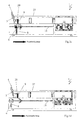
- 1 a to 1 l show a device 1 for producing stack packs 2 from printing sheets 4 fed continuously in a shingled stream 3.
- the printing sheets 4 are, as described in EP 0'623'542 A1, via a conveyor device (not visible) in one Scale stream 3 is fed to a horizontal stack support 5 after it has been previously aligned and placed in the desired scale shape, ie the scale formation must be turned laterally by 180 ° after the printing press. If the scale formation is to be processed by one wrap, it is initially essential to wrap it around another wrap.
- 1a to 1l further show that the device 1 is designed to be mobile and can thus be connected to the display of various printing machines of a company.
- FIG. 1 a shows the device 1 in the empty state with an incoming scale flow 3 and the first support element 6 of a multi-part support device 7 raised above the stack support 5.
- This further consists of a second support element 8, which is also illustrated in the raised state.
- the two support elements 6, 8 are assigned a third support element 9, which is also shown in the ejected position.
- the support elements 6, 8, 9 forming the support device 7 are driven on a guide 10 arranged below the stack support 5, parallel to this, along the stack support 5.
- the support elements 6, 8, 9 are connected, for example, to traction means, such as toothed belts or chains, which are driven along the stack support 5 in the paper running direction and back and can be raised and lowered by controlled adjusting means.
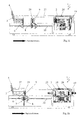
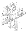
- FIG. 2 An embodiment of the drive arrangement for the support device 7, in particular support element 9, is shown in FIG. 2.
- the latter provides a lateral guide 10, which is fastened to a frame of the device 1 and on which a carriage 11 which is movable along the stack support 5 and on which the support element 9 can be raised and lowered is arranged.
- two columns 12 are provided, on which the support element 9, which has three support plates 13, can be driven vertically by a pneumatic cylinder (not shown).
- the support element 9 is driven along the stack support 5 by toothed belts 14, of which both the upper and the lower run can be seen.
- the drive motor for toothed belt 14 is located at the opposite end of the stack support 5. Toothed belt 15 is provided for driving support element 6 and toothed belt 16 for support element 8.
- the toothed belts 15 to 17 are each deflected around pulleys, one of which is connected to a drive motor, toothed belt 16 being associated with a geared motor 17 and toothed belt 15 with a geared motor 18.
- the support elements 6, 8, like the support element 9, are fastened to their own undercarriage (not illustrated in FIG. 2) and, like the support element 9, are actuated by a pneumatic cylinder.
- a pressing device 19 which can be moved along the stack support 5, is arranged above the stack support 5 and detects a stack package 2 produced on the stack support 5 and transports it into a subsequent strapping device 20.
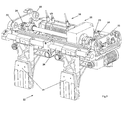
- 3 shows a supporting structure 21 with a pressing part 22 viewed from the pressing device 19 in the opposite direction of the paper travel.
- the supporting structure extends transversely to the paper running direction and is arranged to be movable on both sides by two rollers 23 in a stationary C-shaped running rail (not visible).
- the running rail 27 is provided with a toothed rack (not shown) with which a toothed wheel 24 of a travel drive 25 meshes.
- the press part 22 consists of two press plates 26 which can be adjusted to the format of the printed sheets to be processed on a guide rod 26 arranged above them, transversely to the paper running direction.
- the area of action of the pressing device 19 extends from the stacking support 5 into the strapping device 20.
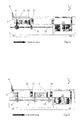
- the support elements 6, 9 of the support device 7 are raised via the stack support 5 in the concept of taking over an end plate 29 which is displaced from the side of the device 1 from a plate magazine between the spaced support elements 8, 9.
- an end plate 29 which, for the front end of a stack in the paper travel direction.
- Stack package 2 is provided. The (front) end plate 29 is now guided between the support elements 8, 9 via the stack support 5 to the front stack end of a stack which is held upright by the support element 6.
- the second support element 8 has now moved downward from the stacking support 5 and the end plate 29 is now held between the support elements 6 and 9.
- the collecting process is maintained and the first support element 6 of the support device 7 can now also be moved downwards, so that the end plate 29 comes to rest on the front end of the stack, supported by the support element 9 (see FIG. 1c).
- the support elements 6, 8 move into their starting position in front of the rear end of the stack (see FIG. 1d). In the situation according to FIG.
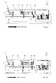
- the stack package 2 is located between two pressing parts 22, 28 of the pressing device 19, so that an end plate 30 can be fed from the side end plate magazine to the rear end of the stack package 2, ie the end plate magazine is between the pressing parts 22, 28, approximately arranged pressing part for the rear stack end.
- Pressed part 22 and the rear end of the stacking package or the supporting element 8 supporting this form a gap into which the rear end plate 30 is inserted.
- Both end plates 29 and 30 have the same dimensions (see Fig. 1g). Subsequently, as shown in FIG.
- the front pressed part 28 and the rear pressed part 22 with the end plate 29 and 30 in between are placed against the ends of the stacking package 2 and at the same time the support elements 8 and 9 are moved out of the stacking area. Meanwhile, stacking continues at the end of the shingled stream.
- the stack of packs 2 gripped by the pressed parts 22, 28 is now transferred to the strapping device 20 on the running rails 27 and the support elements 8, 9 have arrived at the end plate magazine for taking over a front end plate 29. While the front end plate 29 is being moved to the front stack end of the continuously increasing stack, the stack package 2 is finally pressed off in the strapping device 20 and then strapped or bound together.
- the front end plate 29 is supported by the support element 9 at the front end of the stack, the support elements 6, 8 are extended and the strapping is completed.
- the support elements 6, 8 return to the starting position, where, according to FIG. 1d, a new stacking process has already started.
Abstract
Description
Die Erfindung betrifft eine Einrichtung zur Herstellung von Stapelpaketen aus fortlaufend einer sich horizontal erstreckenden Stapelauflage zugeführten, senkrecht aneinandergereiht einen Stapel bildenden Druckbogen, bestehend aus einer die Druckbogen in einem Schuppenstrom der Stapelauflage zuführenden Fördervorrichtung und einer zur Bildung eines Stapelpakets von unten in den Stapel eingreifenden, mehrteiligen Stützvorrichtung, die aus einer Warteposition entlang der Stapelauflage in eine Uebergabeposition, in der das Stapelpaket an eine in eine Umreifvorrichtung verfahrbare Pressvorrichtung übergeben wird, antreibbar ist und ein erstes und zweites Stützelement aufweist, die von unten über die Stapelauflage anhebbar und jeweils dem hinteren resp. dem vorderen Ende eines Stapelpakets zugeordnet sind.The invention relates to a device for the production of Stack packages from continuously a horizontally extending Stack support fed, lined up vertically a stack of printed sheets consisting of a die Feeding printed sheets in a stream of shingles to the stacking support Conveyor and one to form a stack multi-part support device engaging in the stack from below, from a waiting position along the stacking surface in a transfer position in which the stack package to a Transfer movable pressing device into a strapping device is drivable and a first and second support element has, which can be raised from below over the stack support and each of the rear resp. the front end of a stack assigned.
Einrichtungen der eingangs genannten Art werden als Stangenausleger mit der Bezeichnung Avanti von Müller Martini vertrieben und sind u.a. in der EP'0'623'542 A1 beschrieben. Devices of the type mentioned are called pole booms sold by Muller Martini with the designation Avanti and include described in EP'0'623'542 A1.
Diese Einrichtungen sind mit der Auslage einer Druckmaschine verbunden, von der sie die in einem Schuppenstrom anfallenden Druckbogen übernehmen und zu einem lagerfähigen Gebinde formen. Es ist von einer Stange die Rede, die anschliessend zu Druckerzeugnissen wie Zeitschriften, Magazine, Broschuren etc. verarbeitet werden, welche die gesammelten Druckbogen enthalten.These facilities come with the delivery of a printing press connected, from which they accumulate in a stream of scales Take over the printed sheet and form it into a storable container. There is talk of a pole which then closes Printed matter such as magazines, magazines, brochures etc. processed, which contain the collected printed sheets.
Bei diesen Verarbeitungsschritten zur Entsorgung einer Druckmaschine
und zur Vorbereitung der Weiterverarbeitung wird eine
hohe Leistung ohne Einbusse an Zuverlässigkeit verlangt. Gemeint
sind kürzere Zykluszeiten, eine grössere Auswahl hinsichtlich
der Länge einer Stange und kürzere Reststangen, herstellbar
mit einem Stangenausleger.
Aufgabe der Erfindung ist es nun, eine Einrichtung der eingangs
erwähnten Art zu schaffen, mit der die gewünschten Ziele
erreicht werden.In these processing steps for the disposal of a printing press and for preparation for further processing, high performance without loss of reliability is required. What is meant are shorter cycle times, a larger selection with regard to the length of a bar and shorter remaining bars that can be produced with a bar arm.
The object of the invention is now to provide a device of the type mentioned at the outset with which the desired goals are achieved.
Erfindungsgemäss wird diese Aufgabe dadurch gelöst, dass die Stützvorrichtung ein drittes, dem in Papierlaufrichtung vorderen Ende des Stapels resp. Stapelpakets zugeordnetes anhebbares Stützelement aufweist.According to the invention, this object is achieved in that the Support device a third, the front in the paper direction End of the stack resp. Stackable assigned liftable Has support element.
Vorteilhaft ist das dritte Stützelement unabhängig von dem ersten und zweiten Stützelement entlang der Stapelauflage antreibbar gesteuert, wodurch mehr Handlungsfreiheit entsteht, die sich auf eine höhere Produktionsleistung positiv auswirkt.The third support element is advantageous regardless of that first and second support element along the stack support driven driven, which creates more freedom of action, which has a positive effect on higher production output.
Vorzugsweise sind bei einer Einrichtung mit einer dem ersten und dem zweiten Stützelement zugeordneten Trennvorrichtung zur Bildung eines zwischen dem Schuppenstrom der zugeführten Druckbogen und dem auf der Stapelauflage gebildeten Stapel vorgesehenen Trennspaltes das erste und das zweite Stützelement gemeinsam in den Trennspalt anhebbar und bewirken eine exakte Trennung zwischen zwei Druckbogen.Preferably, in the case of a device with a first and the separating device assigned to the second support element Formation of one between the shingled stream of the supplied Printed sheet and the stack formed on the stack support provided separation gap, the first and the second support element can be raised together in the separation gap and cause a exact separation between two printed sheets.
Bei einer Einrichtung mit einer an die Stapelauflage förderwirksam angeschlossenen Umreifungsvorrichtung, in welcher die Stapelpakete mit wenigstens einem Band in Papierlaufrichtung umreift werden, werden die Stapelpakete an der Stapelauflage zweckmässig zwischen einem in Papierlaufrichtung dem vorderen Ende des Stapelpakets zugeordneten Pressteil und einem beabstandeten, dem hinteren Ende des Stapelpakets zugeordneten Pressteil der Pressvorrichtung übergeben und von letzterer in die Umreifvorrichtung transportiert, wodurch kurze Zykluszeiten entstehen. Zweckmässig sind die Stützelemente der Stützvorrichtung an einer gemeinsamen, sich parallel zur Stapelauflage erstreckenden Führung verstellbar angeordnet, sodass eine einfache Führungskonstruktion entsteht.In the case of a device with a support to the stacking support connected strapping device, in which the Stack packages with at least one belt in the paper running direction are strapped, the stack packages on the stack support expediently between one in the paper running direction the front End of the stack package associated press part and a spaced associated with the rear end of the stack Press part transferred to the pressing device and from the latter in transports the strapping device, resulting in short cycle times arise. The support elements of the support device are expedient on a common, parallel to the stack support extending guide adjustable so that a simple guide construction arises.
Bei einer Einrichtung mit einer an der Stapelauflage angeordneten Endplattenzuführvorrichtung für die Herstellung von endseitig mit Endplatten bewehrten Stapelpaketen, wird eine für das hintere Ende eines Stapelpakets bestimmte Endplatte an der Uebergabeposition des Stapelpakets zwischen dem zweiten, an dem hinteren Ende des Stapelpakets anliegenden Stützelement und dem dem hinteren Ende des Stapelpakets zugeordneten Pressteil der Stapelauflage zugeführt, womit eine zuverlässige Endplattenpositionierung auf der Stapelauflage gewährleistet ist.In a device with one arranged on the stacking support End plate feed device for the production of ends stack packages reinforced with end plates, one for the rear end of a stack package specific end plate on the Transfer position of the stack between the second the rear end of the stack package supporting element and the press part associated with the rear end of the stack package fed to the stacking support, with which a reliable end plate positioning is guaranteed on the stack support.
Für den gleichen Zweck wird eine für das vordere Ende eines Stapelpakets bestimmte Endplatte in einem durch das zweite und das dritte Stützelement gebildeten Zwischenraum auf der Stapelauflage gegen die Papierlaufrichtung transportiert.For the same purpose, one is for the front end of one Endplate in a stack package determined by the second and the third support element formed space on the stack support transported against the paper feed direction.
Vorteilhaft ist die Zuführvorrichtung für Endplatten zwischen den Pressteilen der sich in der Uebergabeposition befindenden Pressvorrichtung angeordnet, wodurch sich Stapelpakete jeder gewünschten Länge produzieren lassen.The feed device for end plates between is advantageous the pressed parts of those in the transfer position Pressing device arranged, whereby stack packages each have the desired length produced.
Es erweist sich als einfache Konstruktion, wenn die Pressvorrichtung an oberhalb der Stapelauflage parallel zu dieser verlaufenden Laufschienen fahrbar sind.It turns out to be a simple construction when the pressing device on above the stacking support running parallel to this Running rails are mobile.
Anschliessend wird die Erfindung unter Bezugnahme auf die Zeichnung, auf die bezüglich aller in der Beschreibung nicht näher erwähnten Einzelheiten verwiesen wird, anhand eines Ausführungsbeispiels und einer an diesem dargestellten Verarbeitungsmethode erläutert. In der Zeichnung zeigen:
- Fig. 1a
- eine schematische Darstellung einer erfindungsgemässen Einrichtung bei Produktionsbeginn,
- Fig. 1b
- eine schematische Darstellung der Einrichtung gemäss Fig. 1a, bei der Anbringung einer Endplatte am vorderen Stapelende,
- Fig. 1c
- xeine schematische Darstellung der Einrichtung mit einer am vorderen Stapelende anliegenden Endplatte,
- Fig. 1d
- eine schematische Darstellung der Einrichtung, bei zunehmender Stapellänge,
- Fig. 1e
- eine schematische Darstellung der Einrichtung, bei angehobenen Stützelementen,
- Fig. 1f
- eine schematische Darstellung der Einrichtung, bei der sich ein Stapelpaket vom Stapel getrennt in der Uebernahmeposition einer Pressvorrichtung befindet,
- Fig. 1g
- eine schematische Darstellung der Einrichtung, bei zugeführter hinterer Endplatte,
- Fig. 1h
- eine schematische Darstellung der Einrichtung, bei zwischen zwei Endplatten eingespanntem Stapelpaket,
- Fig. 1i
- eine schematische Darstellung der Einrichtung, bei der sich das eingespannte Stapelpaket in der Umreifungsvorrichtung befindet und die Stützvorrichtung eine vordere Endplatte übernimmt,
- Fig. 1k
- eine schematische Darstellung der Einrichtung, bei der die Umreifung des Stapelpakets eingeleitet ist und die vordere Endplatte dem vorderen Ende des Stapels zugeführt wird,
- Fig. 1l
- eine schematische Darstellung der Einrichtung, bei der die vordere Endplatte am vorderen Ende des Stapels anliegt,
- Fig. 1m
- eine schematische Darstellung der Einrichtung bei der Entnahme des Stapelpakets aus der Umreifvorrichtung,
- Fig. 2
- eine auszugsweise räumliche Darstellung der Antriebsanordnung einer Stützvorrichtung und
- Fig. 3
- eine auszugsweise räumliche Darstellung eines Tragwerks für einen Pressteil einer Pressvorrichtung.
- Fig. 1a
- 1 shows a schematic representation of a device according to the invention at the start of production,
- Fig. 1b
- 1 a, a schematic representation of the device according to FIG. 1 a when an end plate is attached to the front end of the stack,
- Fig. 1c
- x a schematic representation of the device with an end plate resting on the front end of the stack,
- Fig. 1d
- a schematic representation of the device, with increasing stack length,
- Fig. 1e
- a schematic representation of the device, with raised support elements,
- Fig. 1f
- 1 shows a schematic representation of the device in which a stack of packs is separated from the stack in the takeover position of a pressing device,
- Fig. 1g
- a schematic representation of the device, with the rear end plate fed,
- Fig. 1h
- 1 shows a schematic representation of the device, with a stack package clamped between two end plates,
- Fig. 1i
- 1 shows a schematic representation of the device in which the clamped stack is located in the strapping device and the support device takes over a front end plate,
- Fig. 1k
- 1 shows a schematic representation of the device in which the strapping of the stack is initiated and the front end plate is fed to the front end of the stack,
- Fig. 1l
- 1 shows a schematic representation of the device in which the front end plate bears against the front end of the stack,
- Fig. 1m
- 2 shows a schematic representation of the device when the stack package is removed from the strapping device,
- Fig. 2
- a partial spatial representation of the drive arrangement of a support device and
- Fig. 3
- a partial spatial representation of a structure for a press part of a press device.
Die Fig. 1a bis 1l zeigen eine Einrichtung 1 zur Herstellung
von Stapelpaketen 2 aus fortlaufend, in einem Schuppenstrom 3
zugeführten Druckbogen 4. Die Druckbogen 4 werden wie in der
EP 0'623'542 A1 beschrieben über eine Fördervorrichtung (nicht
ersichtlich) in einem Schuppenstrom 3 einer horizontalen Stapelauflage
5 zugeführt, nachdem sie zuvor ausgerichtet und in
die gewünschte Schuppenform versetzt worden sind, d.h., die
Schuppenformation muss nach der Druckmaschine seitlich um 180°
gewendet werden.
Ist die Schuppenformation von einem Wickel zu verarbeiten, ist
vorerst ein Umwickeln auf einen anderen Wickel unerlässlich.
Die Fig. 1a bis 1l zeigen weiterhin, dass die Einrichtung 1
fahrbar ausgestaltet ist und somit an die Auslage verschiedener
Druckmaschinen eines Betriebes anschliessbar ist.
Die Fig. 1a zeigt die Einrichtung 1 im Leerzustand bei einlaufendem
Schuppenstrom 3 und über die Stapelauflage 5 angehobenem
ersten Stützelement 6 einer mehrteiligen Stützvorrichtung
7. Diese besteht weiterhin aus einem zweiten Stützelement 8,
das ebenfalls in angehobenem Zustand veranschaulicht ist. Den
beiden Stützelementen 6, 8 ist ein drittes Stützelement 9 zugeordnet,
das ebenfalls in der ausgestossenen Lage dargestellt
ist. Die die Stützvorrichtung 7 bildenden Stützelemente 6, 8,
9 sind an einer unterhalb der Stapelauflage 5, parallel zu
dieser angeordneten Führung 10 entlang der Stapelauflage 5 angetrieben.
Hierzu sind die Stützelemente 6, 8, 9 beispielsweise mit entlang
der Stapelauflage 5 in Papierlaufrichtung und zurück angetriebenen
Zugmitteln wie Zahnriemen oder Ketten verbunden
und lassen sich durch gesteuerte Stellmittel hochstellen und
absenken. Ein Ausführungsbeispiel der Antriebsanordnung für
die Stützvorrichtung 7, insbesondere Stützelement 9 ist in
Fig. 2 dargestellt. Letztere vermittelt eine an einem Gestell
der Einrichtung 1 befestigte, seitliche Führung 10, an der ein
entlang der Stapelauflage 5 verfahrbares Fahrwerk 11 angeordnet
ist, an welchem das Stützelement 9 anheb- und absenkbar
geführt ist. Dafür sind zwei Säulen 12 vorgesehen, an denen
das drei Stützplatten 13 aufweisende Stützelement 9 von einem
Pneumatikzylinder (nicht ersichtlich) senkrecht antreibbar
ist. Der Antrieb des Stützelementes 9 entlang der Stapelauflage
5 erfolgt durch Zahnriemen 14, von dem sowohl der obere wie
auch der untere Trum erkennbar ist. Der Antriebsmotor für
Zahnriemen 14 befindet sich am entgegengesetzten Ende der Stapelauflage
5. Zahnriemen 15 ist zum Antrieb von Stützelement 6
und Zahnriemen 16 für Stützelement 8 vorgesehen. Die Zahnriemen
15 bis 17 werden jeweils um Pulleys umgelenkt, von denen
eines mit einem Antriebsmotor verbunden ist, wobei Zahnriemen
16 ein Getriebemotor 17 und Zahnriemen 15 Getriebemotor 18 zugeordnet
ist. Die Stützelemente 6, 8 sind wie Stützelement 9
an einem eigenen Fahrwerk (in Fig. 2 nicht veranschaulicht)
befestigt und werden wie Stützelement 9 von einem Pneumatikzylinder
betätigt. In Fig. 1a ist oberhalb der Stapelauflage 5
eine entlang dieser verfahrbare Pressvorrichtung 19 angeordnet,
die ein auf der Stapelauflage 5 gefertigtes Stapelpaket 2
erfasst und in eine anschliessende Umreifungsvorrichtung 20
transportiert.
Von der Pressvorrichtung 19 ist in Fig. 3 ein Tragwerk 21 mit
einem Pressteil 22 entgegen der Papierlaufrichtung betrachtet
dargestellt. Das Tragwerk erstreckt sich quer zur Papierlaufrichtung
und ist beidseits durch zwei Rollen 23 in einer stationären
C-förmigen Laufschiene (nicht sichtbar) fahrbar angeordnet.
An der Unterseite ist die Laufschiene 27 mit einer
Zahnstange (nicht dargestellt) versehen, mit der jeweils ein
Zahnrad 24 eines Fahrantriebes 25 kämmt. Der Pressteil 22 besteht
aus zwei Pressplatten 26, die an einer darüber angeordneten
Führungsstange 26 quer zur Papierlaufrichtung an das
Format der zu verarbeitenden Druckbogen verstellbar sind. Der
Aktionsbereich der Pressvorrichtung 19 erstreckt sich von der
Stapelauflage 5 in die Umreifungsvorrichtung 20. Entlang der
Stapelauflage 5 befindet sich ein in Papierlaufrichtung vorauslaufender
Pressteil 28 der mit Pressteil 22 die Pressvorrichtung
19 bildet, die in Fig. 1a in einer Ausgangsposition
steht. Bei Beginn der Stapelbildung befinden sich die Stützelemente
6, 9 der Stützvorrichtung 7 über die Stapelauflage 5
hochgefahren im Begriff der Uebernahme einer Endplatte 29, die
seitlich der Einrichtung 1 aus einem Plattenmagazin zwischen
die beabstandeten Stützelemente 8, 9 versetzt wird. Im dargestellten
Fall handelt es sich um eine Endplatte 29, die für
das in Papierlaufrichtung vordere Ende eines Stapels resp.
Stapelpakets 2 vorgesehen ist. Die (vordere) Endplatte 29 wird
nun zwischen den Stützelementen 8, 9 über die Stapelauflage 5
an das vordere Stapelende eines Stapels geführt, welches von
Stützelement 6 aufrecht stehend gehalten wird. In Fig. 1b hat
sich inzwischen das zweite Stützelement 8 von der Stapelauflage
5 nach unten entfernt und die Endplatte 29 wird nun zwischen
den Stützelementen 6 und 9 gehalten. Der Sammelvorgang
wird dabei aufrechterhalten und das erste Stützelement 6 der
Stützvorrichtung 7 kann nun auch nach unten versetzt werden,
sodass die Endplatte 29 gestützt durch Stützelement 9 am vorderen
Stapelende zur Anlage kommt (siehe Fig. 1c). Während
sich der Stapel auf der Stapelauflage 5 weiterentwickelt, bewegen
sich die Stützelemente 6, 8 in ihre Ausgangsposition vor
dem hinteren Stapelende (siehe Fig. 1d).
In der Situation gemäss Fig. 1e liegt ein Stapelpaket 2 zwischen
der von dem Stützelement 9 stehend aufrecht gehaltenen
Endplatte 29 und dem zweiten Stützelement 8 vor, das gemeinsam
mit Stützelement 6 aus der Ausgangsposition in eine Trennposition
versetzt worden ist und durch eine den Stützelementen 6,
8 zugeordnete Trennvorrichtung, beispielsweise eine solche wie
in EP 0'623'542 A1 beschrieben, den ankommenden Schuppenstrom
3 vor dem Stapelbeginn unterbricht. Die nicht ersichtliche
Trennvorrichtung schafft einen Spalt, in den anschliessend die
Stützelemente 6 und 8 gemeinsam eingeschoben werden. Stützelement
6 übernimmt die Stützfunktion am vorderen Ende des nachfolgenden
Stapels und Stützelement 8 stützt das hintere Ende
des Stapelpakets 2.
Während die Stapelbildung kontinuierlich fortgesetzt wird, haben
die Stützelemente 8 und 9 das Stapelpaket 2 in eine Position
transportiert, wo es von einer Pressvorrichtung 19 übernommen
werden soll. In dieser Position (siehe Fig. 1f) befindet
sich das Stapelpaket 2 zwischen zwei Pressteilen 22, 28
der Pressvorrichtung 19, so, dass dem hinteren Ende des Stapelpakets
2 eine Endplatte 30 aus dem seitlichen Endplattenmagazin
zugeführt werden kann, d.h., das Endplattenmagazin ist
zwischen den Pressteilen 22, 28, näherungsweise Pressteil für
das hintere Stapelpaketende angeordnet. Pressteil 22 und hinteres
Stapelpaketende bzw. das dieses stützende Stützelement 8
bilden einen Spalt in den die hintere Endplatte 30 eingeschoben
wird. Beide Endplatten 29 und 30 weisen die gleichen Ausmasse
auf (siehe Fig. 1g).
Anschliessend werden gemäss Fig. 1h der in Papierlaufrichtung
vordere Pressteil 28 und der hintere Pressteil 22 mit dazwischenliegender
Endplatte 29 und 30 an die Enden des Stapelpaketes
2 angelegt und gleichzeitig die Stützelemente 8 und 9
aus dem Stapelbereich ausgefahren. Unterdessen wird auch die
Stapelbildung am Ende des Schuppenstromes fortgesetzt.
Das von den Pressteilen 22, 28 erfasste Stapelpaket 2 wird nun
an den Laufschienen 27 in die Umreifungsvorrichtung 20 überführt
und die Stützelemente 8, 9 sind zur Uebernahme einer
vorderen Endplatte 29 an dem Endplattenmagazin angekommen.
Währenddem die vordere Endplatte 29 an das vordere Stapelende
des sich laufend vergrössernden Stapels versetzt wird, wird
das Stapelpaket 2 in der Umreifungsvorrichtung 20 endgültig
abgepresst und anschliessend umreift bzw. zusammengebunden.
In Fig. 1l steht die vordere Endplatte 29 gestützt durch
Stützelement 9 am vorderen Stapelende an, die Stützelemente 6,
8 sind ausgefahren und die Umreifung ist vollzogen. Die Stützelemente
6, 8 kehren beim nächsten Schritt in die Ausgangsstellung
zurück, wo gemäss Fig. 1d ein neuer Stapelprozess
schon begonnen hat.1 a to 1 l show a device 1 for producing stack packs 2 from
If the scale formation is to be processed by one wrap, it is initially essential to wrap it around another wrap. 1a to 1l further show that the device 1 is designed to be mobile and can thus be connected to the display of various printing machines of a company.
FIG. 1 a shows the device 1 in the empty state with an
For this purpose, the
3 shows a supporting structure 21 with a
In the situation according to FIG. 1e, there is a
While the stack formation continues continuously, the
Subsequently, as shown in FIG. 1h, the front pressed
The stack of
In Fig. 1l, the
Claims (9)
Priority Applications (4)
| Application Number | Priority Date | Filing Date | Title |
|---|---|---|---|
| DE50213650T DE50213650D1 (en) | 2002-10-02 | 2002-10-02 | Device for the production of stacked packages |
| EP02405851A EP1405809B1 (en) | 2002-10-02 | 2002-10-02 | Device for forming parcels of stacked products |
| JP2003337963A JP4860103B2 (en) | 2002-10-02 | 2003-09-29 | Apparatus for producing a deposit package |
| US10/676,043 US7021035B2 (en) | 2002-10-02 | 2003-10-02 | Apparatus for producing stack bundles |
Applications Claiming Priority (1)
| Application Number | Priority Date | Filing Date | Title |
|---|---|---|---|
| EP02405851A EP1405809B1 (en) | 2002-10-02 | 2002-10-02 | Device for forming parcels of stacked products |
Publications (2)
| Publication Number | Publication Date |
|---|---|
| EP1405809A1 true EP1405809A1 (en) | 2004-04-07 |
| EP1405809B1 EP1405809B1 (en) | 2009-07-01 |
Family
ID=31985174
Family Applications (1)
| Application Number | Title | Priority Date | Filing Date |
|---|---|---|---|
| EP02405851A Expired - Lifetime EP1405809B1 (en) | 2002-10-02 | 2002-10-02 | Device for forming parcels of stacked products |
Country Status (4)
| Country | Link |
|---|---|
| US (1) | US7021035B2 (en) |
| EP (1) | EP1405809B1 (en) |
| JP (1) | JP4860103B2 (en) |
| DE (1) | DE50213650D1 (en) |
Cited By (4)
| Publication number | Priority date | Publication date | Assignee | Title |
|---|---|---|---|---|
| EP2159177A1 (en) | 2008-08-29 | 2010-03-03 | Müller Martini Holding AG | Device and method for producing piles of printed sheets |
| EP2316767A1 (en) | 2009-11-03 | 2011-05-04 | Müller Martini Holding AG | Device and method for manufacturing printed product stacks |
| DE102011084469A1 (en) * | 2011-10-13 | 2013-04-18 | Robert Bosch Gmbh | separating |
| DE102011088625A1 (en) | 2011-12-14 | 2013-06-20 | Müller Martini Holding AG | Device for manufacturing printed products, has conveying device with which printed products are supplied to stacking surface, where movable support device is provided on which stack is supported at leading end |
Families Citing this family (9)
| Publication number | Priority date | Publication date | Assignee | Title |
|---|---|---|---|---|
| ES2319409T3 (en) * | 2002-07-19 | 2009-05-07 | Ferag Ag | PROCEDURE AND DEVICE FOR FORMING AND SHAFING HORIZONTAL BATTERIES (BARS) OF PRINTED PRODUCTS. |
| ITMI20040927A1 (en) * | 2004-05-07 | 2004-08-07 | Omet Srl | PROCEDURE AND DEVICE FOR SEPARATING AND TRANSFERRING TOWARDS THE PACKAGING A NUMBER OF FLAT OBJECTS SUCH AS PAPER SHEETS, IN PARTICULAR NAPKINS |
| DE502006006570D1 (en) * | 2006-02-02 | 2010-05-12 | Mueller Martini Holding Ag | Method and apparatus for forming stacks |
| US20090112675A1 (en) * | 2007-10-31 | 2009-04-30 | Jeff Servais | Automated order fulfillment system and method |
| EP2520525B1 (en) * | 2011-05-03 | 2018-05-23 | Müller Martini Holding AG | Method for manufacturing stacks of vertical printed products |
| EP2537786B1 (en) | 2011-06-22 | 2018-07-18 | Müller Martini Holding AG | Rod-stack and method for manufacturing this rod-stack from printed products |
| EP3590850B1 (en) * | 2018-07-02 | 2021-05-05 | H+H GmbH & Co. KG | Method and device for stacking and packaging of folded products |
| DE102020101506A1 (en) * | 2020-01-23 | 2021-07-29 | MM Engineering GmbH | Device and method for carrying out packaging steps for flat cardboard goods |
| CN113928903A (en) * | 2021-10-18 | 2022-01-14 | 东莞市浩信精密机械有限公司 | Non-stop paper separating mechanism for book binding machine |
Citations (7)
| Publication number | Priority date | Publication date | Assignee | Title |
|---|---|---|---|---|
| JPS57112266A (en) * | 1980-12-27 | 1982-07-13 | Yamada Kikai Kogyo Kk | Classification device for folded book |
| US4772003A (en) * | 1987-02-24 | 1988-09-20 | Dainihon Insatsu Kabushiki Kaisha | Apparatus for stacking signatures or the like |
| JPH0432459A (en) * | 1990-05-25 | 1992-02-04 | Toppan Printing Co Ltd | Dividing fork driving control method in automatic dividing device for printed book and the like |
| JPH06219622A (en) * | 1993-01-20 | 1994-08-09 | Dainippon Printing Co Ltd | Printed sheet accumulating device |
| US5393196A (en) * | 1991-05-28 | 1995-02-28 | Winkler & Duennebier Maschinenfabrik Und Eisengiesserei Kg | Method and apparatus for stacking of envelopes or the like |
| EP0741101A2 (en) * | 1995-05-05 | 1996-11-06 | CIVIEMME S.r.l. | Method for separating a stack of signatures in a stacker and stacker for performing this method |
| FR2777876A1 (en) * | 1998-04-24 | 1999-10-29 | Realisations Etudes Et Commerc | Automatic stacker for books |
Family Cites Families (6)
| Publication number | Priority date | Publication date | Assignee | Title |
|---|---|---|---|---|
| US4641489A (en) * | 1984-09-28 | 1987-02-10 | World Color Press, Inc. | Machine for handling signatures |
| US4723883A (en) * | 1985-08-09 | 1988-02-09 | Stacker Machine Co., Inc. | Stacker bundler shuttle system |
| US4824093A (en) * | 1988-05-06 | 1989-04-25 | Baldwin Technology Corporation | Handling signatures |
| DE4202540A1 (en) * | 1992-01-30 | 1993-08-05 | Giebeler Gmbh & Co Kg Robert | METHOD AND DEVICE FOR PRODUCING DEFINED STACK OF FOLDED OR UNFOLDED SHEETS OR SHEET-SHAPED OBJECTS |
| JP4318322B2 (en) * | 1993-05-07 | 2009-08-19 | グラプハ−ホルディング・アクチエンゲゼルシヤフト | Apparatus for forming a stack oriented in a vertical direction with respect to papers standing in parallel |
| DE59806580D1 (en) * | 1997-03-18 | 2003-01-23 | Grapha Holding Ag | Device for forming a partial stack which extends perpendicularly to the printed sheets arranged in a row |
-
2002
- 2002-10-02 DE DE50213650T patent/DE50213650D1/en not_active Expired - Lifetime
- 2002-10-02 EP EP02405851A patent/EP1405809B1/en not_active Expired - Lifetime
-
2003
- 2003-09-29 JP JP2003337963A patent/JP4860103B2/en not_active Expired - Fee Related
- 2003-10-02 US US10/676,043 patent/US7021035B2/en not_active Expired - Fee Related
Patent Citations (7)
| Publication number | Priority date | Publication date | Assignee | Title |
|---|---|---|---|---|
| JPS57112266A (en) * | 1980-12-27 | 1982-07-13 | Yamada Kikai Kogyo Kk | Classification device for folded book |
| US4772003A (en) * | 1987-02-24 | 1988-09-20 | Dainihon Insatsu Kabushiki Kaisha | Apparatus for stacking signatures or the like |
| JPH0432459A (en) * | 1990-05-25 | 1992-02-04 | Toppan Printing Co Ltd | Dividing fork driving control method in automatic dividing device for printed book and the like |
| US5393196A (en) * | 1991-05-28 | 1995-02-28 | Winkler & Duennebier Maschinenfabrik Und Eisengiesserei Kg | Method and apparatus for stacking of envelopes or the like |
| JPH06219622A (en) * | 1993-01-20 | 1994-08-09 | Dainippon Printing Co Ltd | Printed sheet accumulating device |
| EP0741101A2 (en) * | 1995-05-05 | 1996-11-06 | CIVIEMME S.r.l. | Method for separating a stack of signatures in a stacker and stacker for performing this method |
| FR2777876A1 (en) * | 1998-04-24 | 1999-10-29 | Realisations Etudes Et Commerc | Automatic stacker for books |
Non-Patent Citations (3)
| Title |
|---|
| PATENT ABSTRACTS OF JAPAN vol. 006, no. 207 (M - 165) 19 October 1982 (1982-10-19) * |
| PATENT ABSTRACTS OF JAPAN vol. 016, no. 206 (M - 1248) 15 May 1992 (1992-05-15) * |
| PATENT ABSTRACTS OF JAPAN vol. 018, no. 592 (M - 1702) 11 November 1994 (1994-11-11) * |
Cited By (6)
| Publication number | Priority date | Publication date | Assignee | Title |
|---|---|---|---|---|
| EP2159177A1 (en) | 2008-08-29 | 2010-03-03 | Müller Martini Holding AG | Device and method for producing piles of printed sheets |
| US8376346B2 (en) | 2008-08-29 | 2013-02-19 | Mueller Martini Holding Ag | Device and method for producing stacks composed of printed sheets |
| EP2316767A1 (en) | 2009-11-03 | 2011-05-04 | Müller Martini Holding AG | Device and method for manufacturing printed product stacks |
| US8413792B2 (en) | 2009-11-03 | 2013-04-09 | Mueller Martini Holding Ag | Method and device for producing stacks composed of printed products |
| DE102011084469A1 (en) * | 2011-10-13 | 2013-04-18 | Robert Bosch Gmbh | separating |
| DE102011088625A1 (en) | 2011-12-14 | 2013-06-20 | Müller Martini Holding AG | Device for manufacturing printed products, has conveying device with which printed products are supplied to stacking surface, where movable support device is provided on which stack is supported at leading end |
Also Published As
| Publication number | Publication date |
|---|---|
| JP4860103B2 (en) | 2012-01-25 |
| DE50213650D1 (en) | 2009-08-13 |
| EP1405809B1 (en) | 2009-07-01 |
| JP2004123387A (en) | 2004-04-22 |
| US7021035B2 (en) | 2006-04-04 |
| US20040065214A1 (en) | 2004-04-08 |
Similar Documents
| Publication | Publication Date | Title |
|---|---|---|
| EP0623542B1 (en) | Device for forming a stack of printed sheets, where these are piled on the edge | |
| EP2072430B1 (en) | Packet gripper for a palletising device and method for palletising packets | |
| DE3735486C2 (en) | ||
| EP0583562B1 (en) | Device for continuous feeding of inner books | |
| DE3203506A1 (en) | DEVICE FOR INSERTING SHEET PACKAGES INTO A MACHINING MACHINE | |
| EP0366038B1 (en) | Device for the zigzag folding and stacking of a web of material | |
| CH667056A5 (en) | METHOD AND DEVICE FOR HANDLING A STACK OF LEAFS. | |
| EP1405809B1 (en) | Device for forming parcels of stacked products | |
| DE3038058A1 (en) | DEVICE FOR STACKING FLAT ITEMS, IN PARTICULAR FOLDING CARTON CUTS | |
| DE3126807A1 (en) | BAR STACKER FOR FOLDED PRINTED SHEETS | |
| EP1816098B1 (en) | Method and device for forming stacks | |
| DE2508745C2 (en) | Device for accumulating individually by means of a transport device fed paper sheets into stacks and for further transporting these stacks | |
| EP1378472A1 (en) | Device for transporting a stack of juxtaposed printed sheets standing on edge, lying on a support | |
| EP0309745B1 (en) | Device for stacking printed products continuously arriving in an imbricated product stream | |
| EP0773179B1 (en) | Device for making auxiliary stacks during continuous pile exchange in a piler of a printing machine | |
| EP1350750B1 (en) | Method and device for forming piles of continuously delivered, flat ojects | |
| DE3911969A1 (en) | DEVICE FOR GIANTLY PUTTING SHEETS, IN PARTICULAR PAPER SHEETS, ONTO A PACK | |
| EP0540505B1 (en) | Installation for stacking of divided panel-like single work pieces or panel packets | |
| DE3931710C2 (en) | Non-stop sheet feeder for sheet-fed rotary machines | |
| EP0741101B1 (en) | Method for separating a stack of signatures in a stacker and stacker for performing this method | |
| EP1199275B1 (en) | Device for making a stack of printed sheets arranged side by side | |
| EP0019036B1 (en) | Device for stacking square-shaped products, in particular so shaped printed matter, periodicals or the like | |
| DE2753048C2 (en) | Method and apparatus for producing a bundled bar from printed sheets | |
| DE2547298A1 (en) | Paper sheet transfer conveyor on scissor lift - has transfer rotor to assemble paper stacks of equal length | |
| EP0810174A2 (en) | Device for vertically stacking printed products |
Legal Events
| Date | Code | Title | Description |
|---|---|---|---|
| PUAI | Public reference made under article 153(3) epc to a published international application that has entered the european phase |
Free format text: ORIGINAL CODE: 0009012 |
|
| AK | Designated contracting states |
Kind code of ref document: A1 Designated state(s): AT BE BG CH CY CZ DE DK EE ES FI FR GB GR IE IT LI LU MC NL PT SE SK TR |
|
| AX | Request for extension of the european patent |
Extension state: AL LT LV MK RO SI |
|
| 17P | Request for examination filed |
Effective date: 20040720 |
|
| AKX | Designation fees paid |
Designated state(s): CH DE FR GB IT LI |
|
| 17Q | First examination report despatched |
Effective date: 20070129 |
|
| GRAP | Despatch of communication of intention to grant a patent |
Free format text: ORIGINAL CODE: EPIDOSNIGR1 |
|
| GRAS | Grant fee paid |
Free format text: ORIGINAL CODE: EPIDOSNIGR3 |
|
| GRAA | (expected) grant |
Free format text: ORIGINAL CODE: 0009210 |
|
| AK | Designated contracting states |
Kind code of ref document: B1 Designated state(s): CH DE FR GB IT LI |
|
| REG | Reference to a national code |
Ref country code: GB Ref legal event code: FG4D Free format text: NOT ENGLISH |
|
| REG | Reference to a national code |
Ref country code: CH Ref legal event code: EP |
|
| REF | Corresponds to: |
Ref document number: 50213650 Country of ref document: DE Date of ref document: 20090813 Kind code of ref document: P |
|
| PLBE | No opposition filed within time limit |
Free format text: ORIGINAL CODE: 0009261 |
|
| STAA | Information on the status of an ep patent application or granted ep patent |
Free format text: STATUS: NO OPPOSITION FILED WITHIN TIME LIMIT |
|
| 26N | No opposition filed |
Effective date: 20100406 |
|
| PGFP | Annual fee paid to national office [announced via postgrant information from national office to epo] |
Ref country code: DE Payment date: 20101020 Year of fee payment: 9 |
|
| PGFP | Annual fee paid to national office [announced via postgrant information from national office to epo] |
Ref country code: GB Payment date: 20101025 Year of fee payment: 9 Ref country code: IT Payment date: 20101023 Year of fee payment: 9 |
|
| PGFP | Annual fee paid to national office [announced via postgrant information from national office to epo] |
Ref country code: FR Payment date: 20111026 Year of fee payment: 10 |
|
| PGFP | Annual fee paid to national office [announced via postgrant information from national office to epo] |
Ref country code: CH Payment date: 20120123 Year of fee payment: 10 |
|
| REG | Reference to a national code |
Ref country code: CH Ref legal event code: PL |
|
| GBPC | Gb: european patent ceased through non-payment of renewal fee |
Effective date: 20121002 |
|
| REG | Reference to a national code |
Ref country code: FR Ref legal event code: ST Effective date: 20130628 |
|
| PG25 | Lapsed in a contracting state [announced via postgrant information from national office to epo] |
Ref country code: CH Free format text: LAPSE BECAUSE OF NON-PAYMENT OF DUE FEES Effective date: 20121031 Ref country code: DE Free format text: LAPSE BECAUSE OF NON-PAYMENT OF DUE FEES Effective date: 20130501 Ref country code: GB Free format text: LAPSE BECAUSE OF NON-PAYMENT OF DUE FEES Effective date: 20121002 Ref country code: LI Free format text: LAPSE BECAUSE OF NON-PAYMENT OF DUE FEES Effective date: 20121031 |
|
| REG | Reference to a national code |
Ref country code: DE Ref legal event code: R119 Ref document number: 50213650 Country of ref document: DE Effective date: 20130501 |
|
| PG25 | Lapsed in a contracting state [announced via postgrant information from national office to epo] |
Ref country code: IT Free format text: LAPSE BECAUSE OF NON-PAYMENT OF DUE FEES Effective date: 20121002 Ref country code: FR Free format text: LAPSE BECAUSE OF NON-PAYMENT OF DUE FEES Effective date: 20121031 |