EP1375138A2 - Printing group pertaining to a printing machine and method for producing a printed product - Google Patents
Printing group pertaining to a printing machine and method for producing a printed product Download PDFInfo
- Publication number
- EP1375138A2 EP1375138A2 EP03103402A EP03103402A EP1375138A2 EP 1375138 A2 EP1375138 A2 EP 1375138A2 EP 03103402 A EP03103402 A EP 03103402A EP 03103402 A EP03103402 A EP 03103402A EP 1375138 A2 EP1375138 A2 EP 1375138A2
- Authority
- EP
- European Patent Office
- Prior art keywords
- cylinder
- cylinders
- printing
- printing unit
- transfer
- Prior art date
- Legal status (The legal status is an assumption and is not a legal conclusion. Google has not performed a legal analysis and makes no representation as to the accuracy of the status listed.)
- Withdrawn
Links
Images


Classifications
-
- B—PERFORMING OPERATIONS; TRANSPORTING
- B41—PRINTING; LINING MACHINES; TYPEWRITERS; STAMPS
- B41F—PRINTING MACHINES OR PRESSES
- B41F13/00—Common details of rotary presses or machines
- B41F13/08—Cylinders
- B41F13/10—Forme cylinders
-
- B—PERFORMING OPERATIONS; TRANSPORTING
- B41—PRINTING; LINING MACHINES; TYPEWRITERS; STAMPS
- B41F—PRINTING MACHINES OR PRESSES
- B41F13/00—Common details of rotary presses or machines
- B41F13/08—Cylinders
-
- B—PERFORMING OPERATIONS; TRANSPORTING
- B41—PRINTING; LINING MACHINES; TYPEWRITERS; STAMPS
- B41F—PRINTING MACHINES OR PRESSES
- B41F13/00—Common details of rotary presses or machines
- B41F13/004—Electric or hydraulic features of drives
- B41F13/0045—Electric driving devices
-
- B—PERFORMING OPERATIONS; TRANSPORTING
- B41—PRINTING; LINING MACHINES; TYPEWRITERS; STAMPS
- B41F—PRINTING MACHINES OR PRESSES
- B41F13/00—Common details of rotary presses or machines
- B41F13/008—Mechanical features of drives, e.g. gears, clutches
-
- B—PERFORMING OPERATIONS; TRANSPORTING
- B41—PRINTING; LINING MACHINES; TYPEWRITERS; STAMPS
- B41F—PRINTING MACHINES OR PRESSES
- B41F13/00—Common details of rotary presses or machines
- B41F13/08—Cylinders
- B41F13/24—Cylinder-tripping devices; Cylinder-impression adjustments
- B41F13/26—Arrangement of cylinder bearings
- B41F13/28—Bearings mounted eccentrically of the cylinder axis
-
- B—PERFORMING OPERATIONS; TRANSPORTING
- B41—PRINTING; LINING MACHINES; TYPEWRITERS; STAMPS
- B41F—PRINTING MACHINES OR PRESSES
- B41F13/00—Common details of rotary presses or machines
- B41F13/08—Cylinders
- B41F13/24—Cylinder-tripping devices; Cylinder-impression adjustments
- B41F13/26—Arrangement of cylinder bearings
- B41F13/30—Bearings mounted on sliding supports
-
- B—PERFORMING OPERATIONS; TRANSPORTING
- B41—PRINTING; LINING MACHINES; TYPEWRITERS; STAMPS
- B41F—PRINTING MACHINES OR PRESSES
- B41F13/00—Common details of rotary presses or machines
- B41F13/08—Cylinders
- B41F13/24—Cylinder-tripping devices; Cylinder-impression adjustments
- B41F13/26—Arrangement of cylinder bearings
- B41F13/32—Bearings mounted on swinging supports
-
- B—PERFORMING OPERATIONS; TRANSPORTING
- B41—PRINTING; LINING MACHINES; TYPEWRITERS; STAMPS
- B41F—PRINTING MACHINES OR PRESSES
- B41F13/00—Common details of rotary presses or machines
- B41F13/08—Cylinders
- B41F13/24—Cylinder-tripping devices; Cylinder-impression adjustments
- B41F13/34—Cylinder lifting or adjusting devices
- B41F13/36—Cams, eccentrics, wedges, or the like
-
- B—PERFORMING OPERATIONS; TRANSPORTING
- B41—PRINTING; LINING MACHINES; TYPEWRITERS; STAMPS
- B41F—PRINTING MACHINES OR PRESSES
- B41F27/00—Devices for attaching printing elements or formes to supports
- B41F27/10—Devices for attaching printing elements or formes to supports for attaching non-deformable curved printing formes to forme cylinders
-
- B—PERFORMING OPERATIONS; TRANSPORTING
- B41—PRINTING; LINING MACHINES; TYPEWRITERS; STAMPS
- B41F—PRINTING MACHINES OR PRESSES
- B41F27/00—Devices for attaching printing elements or formes to supports
- B41F27/12—Devices for attaching printing elements or formes to supports for attaching flexible printing formes
-
- B—PERFORMING OPERATIONS; TRANSPORTING
- B41—PRINTING; LINING MACHINES; TYPEWRITERS; STAMPS
- B41F—PRINTING MACHINES OR PRESSES
- B41F7/00—Rotary lithographic machines
- B41F7/02—Rotary lithographic machines for offset printing
- B41F7/12—Rotary lithographic machines for offset printing using two cylinders one of which serves two functions, e.g. as a transfer and impression cylinder in perfecting machines
-
- B—PERFORMING OPERATIONS; TRANSPORTING
- B41—PRINTING; LINING MACHINES; TYPEWRITERS; STAMPS
- B41P—INDEXING SCHEME RELATING TO PRINTING, LINING MACHINES, TYPEWRITERS, AND TO STAMPS
- B41P2213/00—Arrangements for actuating or driving printing presses; Auxiliary devices or processes
- B41P2213/10—Constitutive elements of driving devices
- B41P2213/20—Gearings
- B41P2213/206—Planetary gears
-
- B—PERFORMING OPERATIONS; TRANSPORTING
- B41—PRINTING; LINING MACHINES; TYPEWRITERS; STAMPS
- B41P—INDEXING SCHEME RELATING TO PRINTING, LINING MACHINES, TYPEWRITERS, AND TO STAMPS
- B41P2213/00—Arrangements for actuating or driving printing presses; Auxiliary devices or processes
- B41P2213/70—Driving devices associated with particular installations or situations
- B41P2213/73—Driving devices for multicolour presses
- B41P2213/734—Driving devices for multicolour presses each printing unit being driven by its own electric motor, i.e. electric shaft
-
- B—PERFORMING OPERATIONS; TRANSPORTING
- B41—PRINTING; LINING MACHINES; TYPEWRITERS; STAMPS
- B41P—INDEXING SCHEME RELATING TO PRINTING, LINING MACHINES, TYPEWRITERS, AND TO STAMPS
- B41P2227/00—Mounting or handling printing plates; Forming printing surfaces in situ
- B41P2227/10—Attaching several printing plates on one cylinder
- B41P2227/11—Attaching several printing plates on one cylinder in axial direction
Definitions
- the invention relates to a printing unit of a printing press and to methods for the production of a printed product according to claim 1 or 10.
- DE 100 08 216 A1 discloses a linearly arranged printing unit, one of which Plane through the axes of rotation of the cylinders and the paper web an obtuse angle lock in.
- the cylinders are mounted in linear guides in guides in the side frame.
- a printing unit is known, the forme cylinder on which Has a circumference in the circumferential direction and a plurality of pressure plates in the longitudinal direction.
- a transfer cylinder cooperating with the forme cylinder has one double the circumference and is in the circumferential direction with a printing blanket and in Longitudinal direction with two, but offset to each other in the circumferential direction Printing blankets executed.
- JP 100 71 694 discloses printing group cylinders with four juxtaposed, and circumferentially offset channels.
- the printing unit cylinders point a so-called double extent.
- CH 3 45 906 discloses a device for bumpless printing, whereby Impacts of four elevators arranged side by side on transfer cylinders double the circumference and joints of four lifts arranged side by side on one Forme cylinders of double circumference are arranged offset from one another.
- a double printing unit is known from DE 198 15 294 A1, the rotation axes the printing unit cylinders are arranged in one plane.
- the cylinders have one four times the width of a newspaper page (double width) and a circumference of one height Newspaper page on.
- the transfer cylinders have endless sleeves, which are on the side are interchangeable through openings in the side wall.
- JP 57-131 561 discloses a double printing unit arranged in one plane Axes of the printing unit cylinders.
- the printing unit cylinders are in their phase arranged to each other that channels for fastening the lifts to each other, and in unroll the two printing units working together.
- DE 34 12 812 C1 also discloses a double printing unit, the Cylinder axes are arranged in a common plane, which is against the plane the web to be printed runs inclined. Starting and stopping the Transfer cylinder takes place along an almost rectilinear direction of movement using double eccentrics.
- EP 08 62 999 A2 discloses a double printing unit with two working together Transfer cylinders, which are used in the eccentric or Double eccentric bushes are stored. In another version, they are stored in levers, which are pivotally mounted eccentrically to the forme cylinder axis.
- EP 10 75 945 A1 has a double printing unit arranged in one plane Axes of the printing unit cylinders are known, with several printing unit cylinders in carriages stored, and arranged for the purpose of putting on and off by means of a supporting wall Guide elements are designed to be mutually variable.
- A1 printing unit cylinders which run along a linear travel are movable to put them on or off each other.
- a drive motor is assigned to each cylinder, which together with the cylinder is moved. The movement takes place in a direction parallel to one common level of the printing unit cylinder lies.
- the invention has for its object a printing unit of a printing press and a To create a process for producing a printed product.
- the cylinders support each other. This diminishes a relative Deflection of the cylinders. It is even a compensation of the bending line (static) of the Forme and transfer cylinder reachable to each other.
- the elevators on the cylinders are not continuous over the length of the cylinders, but are held in circumferentially offset channels, a Channel blow when passing through the channel while rolling two together acting cylinder significantly reduced.
- the channels are in the Case of two channels arranged side by side in the longitudinal direction by 180 ° to one another staggered.
- the arrangement of the printing couple cylinders and the channels is particularly advantageous, that the offset channels of each cylinder in the area of the opposite lying, offset channel of the cooperating cylinder rolls. So one can Dynamic forces are balanced. With a fixed offset angle of 180 ° and linear arrangement of the cylinders lies for all production rates, i. H. Angular velocities, destructive interference before without an offset angle of Channels must be varied depending on the speed or frequency.
- the arrangement of printing unit cylinders of simple scope is particularly advantageous for printed products of smaller and / or variable page size and / or for printing companies with limited space.
- a double-size press without gathering
- a double-size plate change required.
- a double-size printing press in the collective operation it becomes possible to create an affair from two sides, and thereby creating increased flexibility in the printed product.
- the form cylinders can indeed be spaced apart for the purpose of adjustment Transfer cylinder and, if necessary, ink and, if available, dampening unit can be changed be stored, a turning on and off of the transfer cylinder from each other and from associated forme cylinders, however, is advantageously carried out solely by means of a Movement of the transfer cylinder.
- the movement is linear by a specially selected movement in the area of the pressure point Arrangement of the cylinders enables and at the same time switch-on and switch-off devices or - Movements of the forme cylinders avoided. This also contributes to the robust and simple Execution at.
- the transfer cylinders are, for example, in carriages
- a special arrangement of the direction of movement enables fast and safe Parking the forme and impression cylinders as well as the web.
- the transfer cylinders are in levers for this purpose arranged which are pivotally mounted eccentrically to the forme cylinder axis.
- the transfer cylinders are in levers for this purpose arranged which are pivotally mounted eccentrically to the forme cylinder axis.
- the transfer cylinders are in double eccentric bushes stored, which at least in the area close to the pressure point an almost linear and Movement largely perpendicular to the plane of the cylinder axes.
- One version of the printing unit with cylinders is particularly advantageous Scope and arrangement in one plane, with offset, but mutually channels rolling on one another, and with elevators designed as metal printing blankets on the transfer cylinders.
- a first printing unit 01 of a printing press in particular one Rotary printing machine, has a first cylinder 02, z. B. a forme cylinder 02, and an assigned second cylinder 03, e.g. B. a transfer cylinder 03, (Fig. 1).
- their axes of rotation define R02; R03 a level E.
- the form cylinder 02 and the transfer cylinder 03 have in their circumference Circumferential direction on the lateral surface at least one fault, for. B. an interruption 04; 06 in the lateral surface effective when unrolling.
- This interruption 04; 06 may a joint of a leading and a trailing end of one or more Be elevators, for example, by means of magnetic force or cohesive on the Scope are arranged.
- channels 04; 06 or slots 04; 06 act, which pick up the ends of elevators.
- channels 04; 06 designated faults are synonymous with other interruptions 04; 06 on the effective surface area, d. H. the outward-facing surface of the with elevators provided cylinder 02; 03.
- the forme cylinder 02 and transfer cylinder 03 each have at least two channels 04; 06 (or interruptions 03; 04 etc.). These two channels 04; 06 are in Longitudinal direction of the cylinder 02; 03 in a row, and in the circumferential direction to each other staggered.
- Channels 04; 06 are on the two cylinders 02; 03 they arranged at Rotation of the two cylinders 02; 03 each on one of the channels 06; 04 of each other cylinder 03; 04 unroll.
- the offset of the channels is preferably 04; 06 each cylinder 02; 03 approx. 180 ° in the circumferential direction.
- the transfer cylinder 01 of the first printing group 01 forms with a third cylinder 07; via a train 08; z. B. a printing material web 08, a printing point 09.
- This third Cylinder 07 can be used as a second transfer cylinder 07 (FIG. 1) or as a Impression cylinder 07 (Fig. 2), z. B. steel cylinder, or satellite cylinder 07 be executed.
- the axes of rotation R03 and R07 of those forming the printing point 09 Cylinder 03; 07 stretch a plane D in the ON position (see e.g. Fig. 6 or 13).
- Satellite cylinder 07 has two pressure points on its circumference, so preferably one second printing unit, not shown, also in the common plane E. arranged. However, it can also define its own level E, which also depends on the its assigned level D is different.
- FIG. 1 it acts as the second Transfer cylinder 07 third cylinder 07 with a fourth cylinder 11, in particular a second forme cylinder 11 with an axis of rotation R11, together, and forms a second printing unit 12.
- the two printing units 01; 12 form one on both Pages 13 simultaneously printing unit 13, a so-called double printing unit 13th
- the cylinders 07; 11 of the second Printing unit 12 channels 04; 06 with those described above for the first printing group 01 Properties with regard to the number and that of the offset to one another.
- Channels 04; 06 the four cylinders 02; 03; 07; 11 are now preferably arranged so that two Channels 04; 06 two interacting cylinders 02; 03; 07; 11 roll on top of each other.
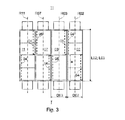
- the forme cylinder 02 and the transfer cylinder 03 have an advantageous design each a length L02; L03, which is four or more widths of a printed page, e.g. B. a newspaper page, e.g. B. 1,100 to 1,800 mm, in particular 1,500 to 1,700 mm and a diameter D02; D03, e.g. B. 130 to 200 mm, in particular. 145 to 185 mm, whose extent U corresponds essentially to the length of a newspaper page, in following "simple scope" (Fig.
- the device is also for other scopes advantageous in which the ratio between diameter D02; D03 and length L02; L03 the cylinder 02; 03 less than or equal to 0.16, in particular less than 0.12, or even is less than or equal to 0.08.
- each of the two cylinders 02; 03 two channels 04; 06 on which each extend continuously over at least one length, which two Widths corresponds to a newspaper page (Fig. 3).
- Each cylinder 02; 03 but also more than two channels 04; 06 may be arranged.
- two channels 04; 06 in alignment, or alternately.
- it can for example with four channels 04; 06 the two the end faces of the cylinders 02; 03 adjacent channels 04; 06 in a common escape, and the two "inside" lying channels 04; 06 in a common escape, but in the circumferential direction be arranged offset to the former (Fig. 4).
- each of the channels 06 of the transfer cylinder 03 there can be a single, continuous one Clamping and / or tensioning device or it can - in the case of more than one Newspaper page widths through continuous channels - several in a row in the longitudinal direction Clamping and / or tensioning devices can be arranged.
- the channels 04 of the forme cylinder 02 for example, also each have a single one or more Clamping devices on.
- the forme cylinder 02; 11 as well as in the Channels 06 of the transfer cylinder 03; 07 a "minigap technology" was used, being in a narrow channel 04; 06 with an inclined leading hooking edge leading end inserted, the elevator to cylinder 02; 03; 07; 11 wound up is, the trailing end also in channel 04; 06 is inserted, and the Anti-slip ends, e.g. B. by means of a rotatable spindle or pneumatic device to be clamped.
- the transfer cylinder 03; 07 have z. B. in an advantageous embodiment (Fig. 3) only two elevators offset in the circumferential direction from each other by 180 °, which each have at least one width, which two widths of a newspaper page equivalent.
- the elevators or channels 04 of the forme cylinders 02; 11 complementary to this and must either, as shown, two continuous, each a length of two newspaper page widths, channels 04, or in pairs Adjacent and aligned channels 04 each having a length of one Have newspaper page width.
- two Clamping devices each have a length that is essentially a width of one Newspaper page corresponds to.
- the forme cylinder 02; 11 are in an advantageous embodiment with four in the longitudinal direction Forme cylinder 02; 11 bendable lifts arranged side by side, which in Circumferential direction a length of slightly above the length of the printed image Newspaper page, and in the longitudinal direction have a width of about one newspaper page.
- arranging continuous channels 04 and only one clamping device per channel 04; 06 which has a length of two widths on a newspaper page, is also possible lifts with a width of two newspaper pages, so-called panorama printing plates, raise.
- each to side I and the "outer" elevators adjacent to side II align and align the "inner” lifts with each other and to the former Are arranged offset by 180 ° (Fig. 4).
- This highly symmetrical arrangement leaves additionally reduce the risk of vibration excitation in level E or avoid which is caused by the non-simultaneous passage of channels 04; 06 on Side I and Side II can result.
- This also alternates between side I and side II alternating tensioning and relaxation of the web 08, and thereby caused Swinging of the web 08 can thereby be avoided.
- the Forme cylinder 02; 11 in an advantageous embodiment with respect to their axes of rotation R02; R11 fixed.
- the forme cylinders 02; 11 however in appropriate devices, e.g. B. in eccentric or double eccentric bushings, in Linear guides or in levers.
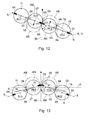
- the transfer cylinder 03; 07 can, as in FIGS. 5 to 7 schematically, as well as in 8 to 11 shown in more detail, along a linear travel path 16, or how in Fig. 12 and 13 schematically and in Fig. 14 and 15 shown in more detail along a curved path 17 to be movable. Travel 16 and 17 and the Transfer cylinder 03; 07 in a print-down position AB are in FIGS. 5, 6 and 12 shown in dashed lines.
- double eccentric bushings in the area of the pressure-on position AN an essentially linear adjustment path 16, in the of Pressure area 09 further away, however, a curved travel path 17 if necessary generate which faster or larger parking of the transfer cylinder 03; 07 of the cooperating transfer cylinder 07; 03 as from the assigned Forme cylinder 02; 11 or vice versa allowed.
- the storage on side I and on side II of the double printing unit 13 is advantageous.
- FIGS. 5 to 11 are exemplary embodiments for the printing group 01; 12 set out, wherein at least one of the transfer cylinders 03; 07 along a linear Travel 16 is movable (Fig. 5):
- the linear travel 16 takes place by means of linear guides not shown in FIG. 5, which are arranged in or on the side frame, also not shown in FIG. 5.
- the bearings in a linear guide are made for the robust and low-vibration Construction preferably on side I and on side II of the double printing unit 13.
- Fig. 5 the course of the web 08 is the one in the print-on position ON Pressure point 09 shown.
- Assign the Transfer cylinder 03; 07 has a circumference which is approximately one Newspaper page corresponds, the angle ⁇ z. B. about 75 ° to 80 °, preferably about 77 °; have the transfer cylinder 03; 07, however, has a scope which is roughly the same Corresponds to the length of two newspaper pages, the angle ⁇ z. B. 80 to 85 °, preferred approx. 83 °.
- This choice of the angle ⁇ contributes to the safe and fast on the one hand Clearing the web 08 and / or the parking cylinder 03; 07 from each other with minimized travel 16 and minimizes negatives Influences on the printing result, which by the measure of a partial wrapping the or the transfer cylinder 03; 07 is significantly influenced (duplication, Lubrication etc.).
- the required linear travel 16 is everyone Transfer cylinder 03; 07 less than or equal to 20 mm for the on / off of the Transfer cylinder 03; 07 to each other / for an exemption from the web 08 in an imprint operation, however, up to 35 mm.
- the angle ⁇ is between Travel 16 and the level of the web 08 preferably greater than or equal to 5 °, z. B. between 5 ° and 30 °, especially between 5 ° and 20 °.
- the angle ⁇ is in particular for forme cylinder 02; 03; 07; 11 simple circumference greater than or equal to 10 °.
- the angle ⁇ is, however, limited in such a way that the angle ⁇ between that in the direction Forme cylinder 02; 11 facing part of level E and the direction of the parking path 16 is at least 90 °. So is a quick and safe parking of the Transfer cylinder 03; 07 simultaneously from the web 08 and the assigned Forme cylinder 02; 11 guaranteed.
- the direction of the travel path 16 (in the direction of the cut-off) is selected such that an angle ⁇ between the plane D and the travel path 16 in the direction of the cut-off is at least 90 ° and at most 120 °, in particular from 90 ° to 115 ° lies.
- the angle ⁇ is again limited in such a way that the angle ⁇ is at least 90 °.
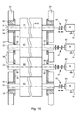
- the double printing unit 13 is multiple, as shown in FIG. 7, for example twice, in a printing unit 19, e.g. B. a so-called. H-printing unit 19, in a common Side frame 20 can be used.
- Fig. 7 was on the separate designation of the Upper double printing unit 13 similar parts for the one below Double printing unit 13 omitted. If all cylinders 02; 03; 07; 11 with one The extent, which essentially corresponds to the length of a newspaper page, can be assumed Installation space, d. H. save at a height h of the printing unit 19. Of course, this applies also for individual printing units 01; 12, for double printing units 13 and for other types configured printing units, which several printing units 01; 12 have. The priority can, however, instead of a saving in height h with an improved Accessibility of cylinders 02; 03; 07; 11, e.g. B. for changing lifts, Cleaning work and washing, maintenance etc., lie.
- Fig. 7 indicates the transfer cylinder 03; 07 in one second possible position along the linear travel path 16, here for example the upper double printing unit 13, e.g. B. for the printing form change in the Print-down position AB (solid), and the lower double printing unit 13, z. B. to continued pressure, is operated in the pressure-on position ON (solid).
- each of the printing units 01; 12 at least one own drive motor 14, indicated only by dashed lines in FIG. 7, for the rotary drive of cylinders 02; 03; 07; 11 on.
- this can be done by a single one Drive motor 14 for the respective printing group 01; 12, which in this case is in a advantageous embodiment first on the forme cylinder 02; 11 drives, and from there via a mechanical drive connection, e.g. B. spur gears, timing belts, etc. on the Transfer cylinder 03; 07 is driven.
- a mechanical drive connection e.g. B. spur gears, timing belts, etc.
- the torque flow can also be advantageous from the drive motor 14 to the Transfer cylinder 03; 07 and from there to the forme cylinder 02; 11 to drive.
- Printing unit 01; 12 in a version of its own, and of the other drives mechanically independent drive motor 14 per cylinder 02; 03; 07; 11 (Fig. 7, below).
- the drive motor 14 is coaxially driven between axis of rotation R02; R03; R07; R11 and motor shaft, if necessary with an angle and / or offset compensating clutch, explained in more detail below. He can, if one "With moving" of the drive motor 14 or a flexible coupling between the Drive motor and the cylinder 02 to be moved if necessary; 03; 07; 11 can be avoided should, however, also be done via a pinion.
- the pin 23 of at least one of the transfer cylinders 03; 07 are for example in bearing housings 24 designed as slides 24 are rotatably supported in radial bearings 27 (in 8 and 9 only the arrangement in the region of an end face of the cylinders 02; 03; 07; 11 ) Shown.
- the bearing housing 24 or slide 24 are in linear guides 26 movable, which are connected to a side frame 27.
- each bearing housing 24 or Carriage 24 provided two linear guides 26 which run parallel to each other.
- the linear guides 26 of two adjacent transfer cylinders 03; 07 run preferably parallel to each other.
- the linear guides 26 can directly in an embodiment, not shown Walls of the side frame 27, in particular on walls of openings in the Side frame 27 may be arranged, which is almost perpendicular to the end face of the cylinder 02; 03; 07; 11 run.
- the side frame 27 has an opening an insert 28, e.g. B. a so-called. Bell 28 on.
- the linear guides 26 are on or in this bell 28 arranged.
- the bell 28 has an area which is in the direction Cylinder 02; 03; 07; 11 emerges from the alignment of the side frame 27.
- the Linear guides 26 are arranged in or on this area of the bell 28.
- the distance between the two opposite side frames 20 (only one shown) is oriented i. d.
- the broadest aggregate e.g. B. on the wider inking unit 21, and usually causes a correspondingly longer pin on the cylinders 02; 03; 07; 11.
- the pins of the cylinders 02; 03; 07; 11 can be kept as short as possible.
- the bell 28 has a cavity 29, which at least is partially arranged at the level of the side frame 20.
- this cavity 29 are, as shown schematically in Fig. 9, the rotary drives of the cylinders 02; 03; 07; 11 with the pins of the cylinders 02; 03; 07; 11 connected.
- Particularly advantageous when driving cylinders 02; 03; 07; 11 can also drive connections such. B. cooperating drive wheels 30, be accommodated in this cavity 29.
- On the transfer cylinder 03; 07 can in advantageous embodiment (Fig. 9) with drive motor 14 fixed to the frame between Transfer cylinder 03; 07 and drive motor 14 an angle and offset compensating clutch 61 may be arranged to the on and off movement of the Transfer cylinder 03; 07 to compensate.
- This can be a double joint 61 or in an advantageous embodiment as an all-metal coupling 61 with two torsionally rigid but axially deformable plate packs are executed.
- the all-metal clutch 61 can at the same time compensate for the offset and the resulting change in length. It is essential that the rotary movement is transmitted without play.
- the clutch 62 is at least a slight angle and offset compensating clutch 62 executed.
- This is also more advantageous Design as an all-metal coupling 62 with two torsionally rigid but axially deformable Lamella packs executed. The linear movement is due to the axial direction positively connected to the pin 51 or a shaft of the drive motor 14 Lamella packs added.
- the Cavity 29 can be limited in a simple manner by means of a cover 31 (dashed) without that this increases the width of the machine or from the side frame 20 protrudes. The cavity 29 can then be encapsulated.
- the arrangement of the bell 28 thus shortens the length of the pins, which is a reduction which results in vibration and enables a simple and variable construction, which are suitable for a wide variety of drive concepts, and for more extensive ones Identical construction the change between the concepts - with or without Drive connections, with or without lubricant, with or without additional Couplings - allowed.
- the drive of the respective bearing housing 24 or slide 24 in the linear guides 26 takes place in the embodiment shown schematically in FIG. B. by means of linear Drives 32, e.g. B. each a screw 32, z. B. a threaded spindle, which of an electric motor, not shown, is driven.
- the electric motor can do this be controllable with respect to a rotational position.
- To limit the travel in the ON position can be a fixed but adjustable stop for the bearing housing 24 be provided.
- the drive of the bearing housing 24 can also be done by means of a lever mechanism respectively. This can also be done by means of an electric motor or at least be driven by a pressure medium cylinder. Will the Lever mechanism by means of one or more pressurizable medium Cylinder driven, so the arrangement is the actuating movement on the two sides I and II synchronizing synchronous spindle is an advantage.
- the connection of the transfer cylinder 03; 07 to the side frame 20 or the bell 28 is designed as follows in the exemplary embodiment according to FIG. 9:
- the bell 28 has supporting walls 33 on both sides of the slide 24 to be guided, which one of the two corresponding parts of the linear guide 26. this part can possibly already be part of the support wall 33, or incorporated into this.
- the other corresponding part of the linear guide 26 is arranged on the slide 24 or incorporated into it or having it.
- the Carriage 24 through two such, on two opposite sides of the carriage 24 arranged linear guides 26 out.
- the on the support walls 33 (or without bell 28 directly on the side frame 20) arranged parts of the guides 26 thus include the arranged between them Carriage 24.
- the active surfaces of the side frame 20 or the bell 28 connected parts of the linear guide 26 have in the facing the pin 23 Half space.
- the two parts of the two guides 26 in the ideal state allow movement of the slide 24 only with a degree of freedom as a linear movement. For this is the entire arrangement in a perpendicular to the axis of rotation R03; R07 and perpendicular to Direction of movement of the carriage 24 lying direction against each other essentially tensioned without play.
- the part of the guide close to the forme cylinder points (in Fig. 9 with larger dimensions) on a clamping device, not shown.
- the carriage 24 mounted in the manner described has, for. B. on a radial after Inside facing side of the transfer cylinder 03; 07 facing Recess, the radial bearing 27 receiving the pin 23.
- Fig. 10 and 11 have the active surfaces of the parts of the linear guide 26 connected to the side frame 20 or the bell 28 in the half-space facing away from the pin 23.
- the carriage 24 has the parts associated with it Linear guide 26 in a side frame 20 or bell 28 facing Recess on. These parts can be arranged in the recess as components, or but already in the carriage 24 in an inwardly facing surface of the recess be incorporated.
- FIG. 10 and 11 have the active surfaces of the parts of the linear guide 26 connected to the side frame 20 or the bell 28 in the half-space facing away from the pin 23.
- the carriage 24 has a to the transfer cylinder 03; 07 facing recess in which the radial bearing 27 for receiving the pin 23 is arranged.
- a running surface for rolling elements of the radial bearing 27 designed as a rolling bearing 27 already incorporated in an inward surface of the recess.
- the parts of the guides 26 arranged on the slide 24 thus comprise the carrier 36, or the parts arranged on the carrier 36, on the side frame 20 or on the bell 28 of the guides 26.
- At least one of the two the transfer cylinder 03; 07 assigned carrier 36 has in an advantageous embodiment an oriented in the direction of movement of the slide 24, Elongated hole not visible in the figures for carrying out the linear movement Pin 23 on.
- This elongated hole is also not at least partially aligned with one visible, arranged in the bell 28 (or in the associated side frame 20) Long hole.
- These slots are from the pin 23 or one with the pin 23rd connected shaft, which is used for the rotary drive of the Transfer cylinder 03; 07 with a drive wheel 30 (see FIG. 9) or the Drive motor 14 is in drive connection.
- Fig. 11 shows the execution of a as a lever mechanism executed actuating means.
- the carriage 24 is articulated via a coupling 37 with a lever 38 connected, which around a substantially parallel to the axis of rotation R03; R07 the transfer cylinder 03; 07 extending axis is pivotable. in the Embodiments are for synchronizing the actuating movement of both Transfer cylinder 03; 07 the coupling 37 of the two adjacent carriages 24 for the interacting transfer cylinder 03; 07 with the three-arm lever 39 executed lever 38 articulated.
- the lever 38 is driven by means of at least one actuator 39, e.g. B. by means of one or by means of two (as in FIG.
- the arrangement of stops 41 is advantageous against which the respective slide 24 is placed in the ON-ON position.
- These attacks are adjustable to adjust the end position for the transfer cylinder 03; 07 to enable in which their axes of rotation R03; R07 to lie in level E. come.
- the system becomes very rigid when the slide 24 hits the stop 41 or the stops 41 (two in FIG. 10) are pressed with great force.
- each coupling 37 has the type of A strut 42, e.g. B. a plate spring assembly 42. During pressure on position To the spring assembly 42 of the one transfer cylinder 03; 07 is compressed is the other transfer cylinder 07; 03 associated spring assembly 42 under Tensile stress.
- An adjusting device can be used for the exemplary embodiments in FIGS be provided, which, especially during assembly and / or when Configurations and / or conditions have changed, a basic setting for the Distances of the axis of rotation R02; R03; R07; R11 enables. Individuals can do this the cylinder 02; 03; 07; 11, e.g. B. the forme cylinder 02; 11, possibly in an eccentric bushing be stored. At least one of the transfer cylinders 03; 07 can Adjustment can be adjustable in a radial direction.
- the Side frame 20 or the bell 28 associated parts of the linear guides 26 or Carrier 36 in elongated holes sufficient for adjustment purposes with the side frame 20 or the bell 28 may be connected.
- an eccentric and lockable bearing of the radial bearing 27 in the carriage 24 is possible.
- FIGS. 12 to 18 are exemplary embodiments for the printing group 01; 12 set out, wherein at least one of the transfer cylinders 03; 07 along one Curved travel 17 is movable (Fig. 12):
- one of the transfer cylinders 03 pivoted about a pivot axis S.
- the pivot axis S is here z. B. in the level E.
- the lever 18 has a length between the storage of the Axis of rotation R03; R07 of the transfer cylinder 03; 07 and the pivot axis S which is larger than the distance of the axis of rotation R03; R07 des Transfer cylinder 03; 07 from the axis of rotation R02; R11 of the assigned Forme cylinder 02; 11 in print-on position ON. This means that it is switched off simultaneously of cooperating transfer cylinder 03; 07 and the associated Forme cylinder 02; 11, and vice versa for starting.
- pivot axis S can in particular also, as described in more detail below, in otherwise eccentric to the axis of rotation R02; R11 of the assigned Forme cylinder 02; 11, e.g. B. at a distance from the plane E.
- the Storage in a lever 18 is preferably carried out on side I and on side II of the Double printing unit 13.
- FIGS. 12 and 13 are the course of the web 08 through the ON in the print-on position located printing point 09 shown.
- Point the transfer cylinder 03; 07 has a circumference which is approximately one Newspaper page corresponds, the angle ⁇ z. B. about 75 ° to 80 °, preferably about 77 °; have the transfer cylinder 03; 07, however, has a scope which is roughly the same Corresponds to the length of two newspaper pages, the angle ⁇ z. B. 80 to 85 °, preferred approx. 83 °.
- this choice of the angle ⁇ contributes to the safe and quick release the web 08 and / or the parking cylinder 03; 07 from each other minimized travel 16 at.
- it minimizes negative influences on the Printing result which is determined by the extent of partial wrapping of the Transfer cylinder 03; 07 is significantly influenced (duplication, lubrication etc.)
- the double printing unit 13 (here in a linear design) is multiple, as in FIG. 14 shown for example twice, in a printing unit 19, for. B. the so-called H-printing unit 19, can be used in the common side frame 20.
- Fig. 14 the separate Name of the parts identical to the upper double printing unit 13 for each double printing unit 13 located below. The advantages of this arrangement will be refer to the comments on FIG. 7.
- Fig. 13 indicates the dashed (but exaggerated for clarity) Transfer cylinder 03; 07 in a second possible position along the travel path 17 at, here, for example, the upper double printing unit 13, z. B. to Printing form change, in the print-down position AB, and the lower double printing unit 13, z. B. for continued production, is operated in the print-on position ON.
- each of the printing units 01; 12 at least one own drive motor 14 for the rotary drive of the cylinders 02; 03; 07; 11 on.
- this can be done by a single one Drive motor 14 for the respective printing group 01; 12, which in this case is in a advantageous embodiment first on the forme cylinder 02; 11 drives, and from there via a mechanical drive connection, e.g. B. spur gears, timing belts, etc. on the Transfer cylinder 03; 07 is driven.
- a mechanical drive connection e.g. B. spur gears, timing belts, etc.
- the torque flow can also be advantageous from the drive motor 14 to the Transfer cylinder 03; 07 and from there to the forme cylinder 02; 11 to drive.
- the printing group 01; 12 in one Version with its own, and mechanical from the other drives independent drive motor 14 per cylinder 02; 03; 07; 11 to a high degree Flexibility (Fig. 14 shown in dashed lines for the upper double printing unit 13).
- the type of drive from FIG. 14 (top and bottom) are shown as examples and thus to the other printing units 01; 12 or the other double printing unit 13 to be transferred.
- the drive motor 14 is coaxially driven between axis of rotation R02; R03; R07; R11 and motor shaft, possibly over the above already Clutches 61; 62.
- the Drive can, if a "moving with” the drive motor 14 or a flexible coupling between the drive motor and the cylinder 02 to be moved if necessary; 03; 07; 11 should be avoided, but also be done via a pinion.
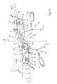
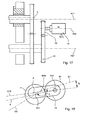
- Fig. 15 shows a side view, of two each on the front Transfer cylinder 03; 07 (dashed) arranged pin 23 only one is visible.
- the lever 18 is pivotally mounted about the pivot axis S, which is preferably with respect to the side frame 20 is stationary (but possibly adjustable).
- the axes of rotation R02; R03; R07; R11 of the cylinder 02; 03; 07; 11 are in the shown execution in print-on position again in a plane E, which here with the plane D between the cylinders 03; 07 coincides.
- the pivot axis S of the lever 18 is eccentric to the axis of rotation R02; R11 des Forme cylinder 02; 11 arranged and lies outside the plane E or D.
- the toggle mechanism 46 is articulated with the lever 18 and connected to a pivot point fixed to the frame.
- Advantageously double acting pressure medium cylinder acts z. B.
- the adjusting means 44 can the two adjusting means 44 connecting shaft 47, z. B. have a synchronous shaft 47 or be connected to one.
- a stop 48 is provided for each lever 18, which is preferably adjustable.
- the drive and actuating means 44; 46 are designed and arranged such that a Parking the transfer cylinder 03; 07 each in the direction of the obtuse angle ⁇ (for straight web run 180 ° - ⁇ ) between web 08 and level D or E.
- the eccentricity e-S of the pivot axis S to the axis of rotation R02; R11 des Forme cylinder 02; 11 is between 7 and 15 mm, in particular about 9 to 12 mm.
- the Eccentricity e-S is in the position of the transfer cylinder 02; 03; 07; 11, d. H.
- the Axes of rotation R03; R07 are in the above Level D, oriented so that an angle ⁇ -S between the plane D of the cylinder 03; 07 and the Connection plane V of the pivot axis S and the axis of rotation R02; R11 between 25 ° and 65 °, advantageously between 32 ° and 55 °, in particular between 38 ° and 52 °, the pivot axis S preferably in the range of an obtuse angle ⁇ between level D and the incoming or outgoing web 08, and further from the printing point 09 is spaced as the axis of rotation R02; R11 of the associated forme cylinder 02; 11th With vertical, and, except for one possibly caused by partial wrapping Offset, straight web run and an angle of 77 ° between the plane D and the plane Bahn 08, the eccentric e-S z. B. an angle of 12 to 52 °, advantageously 19 to 42 °, in particular 25 to 39 ° to the horizontal H.
- the axis of rotation R02; R11 of the forme cylinder 02; 11 is adjustable, e.g. B. also eccentric to its attachment to the side frame 20, here to a bore 49, stored.
- a pin 51 of the forme cylinder 02; 11 in one Eccentric bearing 52 or an eccentric bearing bush 52 arranged in the Bore 49 is pivotally mounted.
- a pivot axis S51 of the forme cylinder 02; 11 is about an eccentricity of 5 to 15 mm, in particular about 7 to 12 mm eccentric to the axis of rotation R02; R11 des Forme cylinder 02; 11 and is located outside of level E.
- the eccentricity e-S51 is in the position of shape and assigned Transfer cylinder 02, 03; 11, 07, d. H.
- the axes of rotation R02, R03 or R11, R07 lie in the plane E, oriented so that an angle ⁇ -S51 between the plane E of the Pair of cylinders 02, 03 or 11, 07 and a connecting plane of the pivot axis S51 and the axis of rotation R02; R11 of the forme cylinder 02; 11 between 25 ° and 65 °, advantageously between 32 ° and 55 °, in particular between 38 ° and 52 °.
- the pivot axis S5 is preferably in a half-plane, which is more distant from the axis of rotation R03; R07 of the assigned transfer cylinder 03; 07 as the axis of rotation R02; R11 des assigned forme cylinder 02; 11 lies.
- the swivel axis S51 for the eccentric mounting of the forme cylinder 02; 11 falls in Embodiment with the pivot axis S of the lever 18 together.
- the two pivot axes S51 are in the pressure-on position AN (and / or S) and S23 of a pair of forme and transfer cylinders 02, 03; 11, 07 arranged on two different sides of level E.
- the position of the forme cylinder 02; 11 accordingly the desired position in relation to the level E or with regard to the required distance to the transfer cylinder 03; 07 for the pressure on position slight rotation of the eccentric bearing 52 adjustable. This location will fixed after setting by means not shown.
- the axes of rotation R03; R07 are on level D, oriented so that an angle ⁇ -S23 between the plane D and the connecting plane of the Swivel axis S-23 and the rotation axis R07 (R03) between 70 ° and 110 °, advantageously between 80 ° and 100 °, in particular between 85 ° and 95 °.
- the angle ⁇ -S23 should be approx. 90 °.
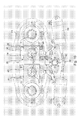
- FIG. 16 shows an embodiment according to FIG. 15 in a representation of a section given along the plane E.
- the pin 51 of the forme cylinder 02; 07 are in Bear 54, e.g. B. rolling bearings 54, rotatably mounted. To a setting or a To be able to make corrections to the page register is made possible in an advantageous manner Execution of this bearing 54 or an additional thrust bearing, not shown Movement of the forme cylinder 02; 11 or its pin 51 in the axial direction.
- the Bearings 54 are arranged in the eccentric bearing 52 or eccentric bearing bush 52, which in turn is arranged pivotably in the bore 49 in the side frame 20. It can in addition to the eccentric bearing bush 52 and the bearing 54 Bearing rings and plain or roller bearings arranged between bore 49 and pin 51 his.
- the lever 18 is on a to the forme cylinder 02; 07 out of the side frame 20 protruding part of the bearing bush 52, and pivotally mounted relative to this.
- the Lever 18 takes in its end remote from the pivot axis S the pin 23 of the Transfer cylinder 03; 07 on which rotates in a bearing 56, and this in Case of the transfer cylinder 07, pivotable in one around the pivot axis S-23 Eccentric bearing 57 or in an eccentric bearing bush 57 is arranged.
- a Such pivotable bearing bush 57 can, if necessary, also for both Transfer cylinder 03; 07 be arranged.
- the side frame advantageously has, at least on one drive side of the printing press 20 recesses 58 in which the pin 23 of the transfer cylinder 03; 07 are pivotable.
- the actuating means 46; 53 or drive means 44 are not shown in FIG. 8 shown.
- the rotary drive of the cylinders 02; 03; 07; 11 takes place by means of separate mechanically from the drive of the other cylinder 02; 03; 07; 11 independent Drive motors 14, which are preferably arranged fixed to the frame.
- the latter has the Advantage that the drive motors 10 do not have to be moved.
- the all-metal coupling 61 at the same time compensates for the offset and the resulting change in length, whereby the rotational movement is transmitted without play.
- the drive of the forme cylinder 02; 11 has between pin 51 and drive motor 14 the at least one axial relative movement between cylinder 02; 11 and Drive motor 14 receiving clutch 62, which, in addition, manufacturing tolerances and any necessary adjustment movements of the forme cylinder 02; 11 for adjustment purposes to be able to accommodate, at least minor angles and offset compensating can be executed.
- All-metal coupling 62 executed, which the axial movement by the in axial Direction positively with the pin 51 or a shaft of the drive motor 14 connected plate packs.
- a paired drive can also be provided by the Drive motor (possibly via further gear parts, not shown) by a pinion 59 a drive wheel 61 of the transfer cylinder 03; 07 if, for example, a special torque flow is to be achieved.
- An axis of rotation R59 of the pinion 59 is then preferably fixed to the frame in this way arranged that one of the rotation axis R59 of the pinion 59 and the Pivot axis S of the lever 18 defined straight line G1 with one of the pivot axis S of the lever 18 and the axis of rotation R03; R07 of the transfer cylinder 03; 07 specified plane E18 an opening angle ⁇ in the range of + 20 ° to - 20 ° includes.
- one of the axes of rotation R02; R11 des assigned forme cylinder 02; 11 and the axis of rotation R59 of the pinion 59 straight line G2 with the axis of rotation R59 of the pinion 59 and the Pivot axis S of the lever 18 defined straight line G1 an opening angle ⁇ im Range from 160 ° to 200 °.
- the printing point is 03; 07 and a z. B. as Satellite cylinder 07; 03 executed impression cylinder 07; 03 formed, so can also forme and transfer cylinder 02; 11; 03; 07 have a simple scope and the associated impression cylinder 07; 03 be made many times larger.
- the training mentioned also advantageously increases Rigidity of the printing unit reached. This is particularly beneficial in connection with Cylinders 02; 03; 07; 11, which have a length that is at least four or even six standing printed pages, especially newspaper pages, corresponds.
- At least one of the is advantageous Transfer cylinder 03; 07 adjustable so far that the retracted web 08 during of the printing operation by means of other printing units without contact through the printing point 09 is feasible.
- the cylinders 02; 03; 07; 11 can be used for all exemplary embodiments as described either in pairs or individually, each with its own drive motor 14 be driven.
- a drive is also possible, wherein one of the forme cylinders 02; 11 of a printing group 01; 12 its own drive motor 14, and the remaining cylinders 02; 03; 07; 11 of the printing group 01; 12 a common Have drive motor 14.
- a configuration of four or five cylinders 02; 03; 07; 11 with three drive motors 14 can be advantageous: in the case of a double printing unit 13 z. B.
- the four cylinders 02; 03; 07; 11 each in pairs by a drive motor 14 depending on the requirement of Forme cylinder 02; 11 or from the transfer cylinder 03; 07 ago driven by rotation.
- the drive wheels 30 each forming a transmission between the forme cylinder 02; 11 and the respectively assigned transfer cylinder 03; 07 each form with the assigned drive motor 14 a drive connection.
- the two pairs of Drive wheels 30 are preferably arranged relative to one another in such a way that they disengage stand, for example, by axially offset arrangement, d. H. in two Drive levels.
- the design of the co-operating drive wheels (30) can be advantageous here. between forme and transfer cylinder 02, 03; 11, 07 each with one Straight toothing in order to move one of the two cylinders 02; 03; 07; 11 enable, but without changing the relative position in the circumferential direction.
- the latter also applies to a possibly arranged pinion between the drive motor 14 and the Drive wheel of the forme cylinder 02; 11 when the pair on the forme cylinder 02; 11 not is coaxially driven.
- the in Fig. 9 and 11 drive situations shown in each case are shown on the two Versions for the realization of the linear movement to be transferred alternately.
- the drive motors 14 are of an advantageous design for all the cases mentioned arranged fixed to the frame. Should the cylinder 02; 03; 07; 11 driving drive motor 14 deviating from this, however, be arranged in a cylinder-fixed manner, so it can during the Actuating movement and / or adjustment of the cylinder 02; 03; 07; 11 in a variant also on a corresponding (or the same) tour or corresponding lever, e.g. B. carried on an outside of the side frame 20 become.
- the drive motor 14 is advantageous as an electric motor, in particular as Asynchronous motor, synchronous motor or as a DC motor.
- a gear 63 is arranged between each of the drive motors 14 and cylinder 02 to be driven; 03; 07; 11 .
- This gear 63 can be connected to the drive motor 14 attachment gear 63, z. B. a Planetary gear 63 be.
- it can also be designed as a different one Reduction gear 63, e.g. B. from pinion or belt and drive wheel.
- the drive units each encapsulated, d. H. each with its own lubricant chamber.
- One of the above single encapsulation extends around the paired drive of two Cylinders 02, 03; 11, 07 or - especially in the case of the bell described above 28 - around both couples.
- a bell 28 can also be used for a pair of two cylinders 02; 03; 07; 11 be executed. The latter is, for example, in the sense of a Modularization is an advantage.
- the double-width printing press of simple size has a high degree of variability especially in the grading of the possible page numbers in the product, in the so-called "Escapade". While the strength per booklet (layer) for the printing press with double Scope and simple width in the collection operation (i.e. maximum product strength) only can be varied in steps of four printed pages, the double width described Printing machine of simple scope a "fling" from two sides (z. B. in Newspaper printing). The product strength and especially the "distribution" of the printed pages on different issues of the overall product or products is considerably more flexible.
- the partial web is either on one different folding former and / or folder for the corresponding partial web led, or it is turned to the escape of the latter. I.e. in the second
- the partial web falls before, during or after turning, but before merging with the "straight tracks", brought into the correct longitudinal or cutting register. This is in dependence on the channels 04; 06 one Cylinder 02; 03; 07; 11 in an advantageous embodiment by appropriate execution of Turning decks (e.g. preset distances between the bars or the path sections) considered.
- the fine adjustment or control is made with the travel ranges of the Cutting register regulation for the relevant partial web and / or partial web strand made to partial lanes of two different running levels if necessary to bring each other in register.
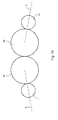
- the forme cylinder 02; 11 is now in the circumferential direction with and in the longitudinal direction At least four standing printed pages can be loaded in broadsheet format (Fig. 20).
- this forme cylinder 02; 11 also optionally in the circumferential direction with two and in the longitudinal direction with at least four lying printed pages in tabloid format (Fig. 21) or in the circumferential direction with two and in the longitudinal direction with at least eight standing printed pages in book format (Fig. 22) or in the circumferential direction with four and in Longitudinal direction with at least four lying printed pages in book format (Fig. 23) by means of one and its longitudinal direction in the circumferential direction of the forme cylinder 03 at least one flexible printing plate that can be arranged on this.
- the double printing unit is with four standing print pages in broadsheet format appropriate web width for the production of two each from one layer existing products in broadsheet format with four printed pages in one product and four printed pages in the other product or with two printed pages in the one Product and six printed pages can be used in the other product.
- a three it is for the production of each corresponding printed pages corresponding web width two single layer products in broadsheet format with four printed pages in one product and two printed pages can be used in the other product.
- the double printing unit 13 is in the case of four standing printing pages Broadsheet format corresponding web width for the production of one from two layers existing product in broadsheet format with four printed pages in one position and four printed pages in the other layer or two printed pages in one layer and six Print pages can be used in the other position.
- Broadsheet format corresponding web width for the production of one from two layers existing product in broadsheet format with four printed pages in one position and four printed pages in the other layer or two printed pages in one layer and six Print pages can be used in the other position.
- three standing printed pages appropriate web width it is for the production of a two-ply Product in broadsheet format with four printed pages in one position and two Print pages can be used in the other position.
- the double printing unit for the production is in a gradation of four lying on the forme cylinder 02; 11 arranged printed pages changeable products ("four-sided") can be used in tabloid format.
- the double printing unit 13 is four, three or two lying Print pages or a lying print page corresponding web width for the Producing one from a layer in the order above with sixteen or Product consisting of twelve, eight or four printed pages in tabloid format usable.
- the double printing unit is in tabloid format with four lying printing pages appropriate web width for the production of two each from one layer existing products in tabloid format with eight printed pages in one product and eight printed pages in the other product or with four printed pages in the one product and twelve printed pages can be used in the other product.
- the double printing unit 13 is for the production in one Gradation of eight standing on the forme cylinder 02; 11 arranged printed pages changeable ("eight page jump") products can be used.
- Double printing unit 13 for the production of two, each consisting of one layer Book format products with sixteen printed pages in one product and sixteen Printed pages in the other product or twenty-four printed pages in the one Product and eight printed pages can be used in the other product.
- a six standing printed pages in book format corresponding web width it is for the Production of two single-layer products in book format sixteen printed pages in one product and eight printed pages in the other Product can be used.
- the double printing unit 13 for the Making one from one layer in the above order at thirty two or twenty-four or sixteen or eight printed pages of existing product in the Book format usable.
- the double printing unit is in book format with four lying printing pages appropriate web width for the production of two each from one layer existing products in book format with sixteen printed pages in one product and sixteen printed pages in the other product and twenty-four printed pages in one product and eight printed pages can be used in the other product.
- the three lying printed pages in book format corresponding web width Production of two single-layer products in book format sixteen printed pages in one product and eight printed pages in the other Product can be used.
- the two partial web strands are folded along different hoppers and then guided into a common folder, so the above is for the Distribution of the product on different, summarized booklets or layers with the variable page number described apply.
Landscapes
- Mechanical Engineering (AREA)
- Engineering & Computer Science (AREA)
- Rotary Presses (AREA)
- Feeding Of Articles By Means Other Than Belts Or Rollers (AREA)
- Supply, Installation And Extraction Of Printed Sheets Or Plates (AREA)
- Printing Methods (AREA)
- Manufacturing Of Printed Wiring (AREA)
- Printers Or Recording Devices Using Electromagnetic And Radiation Means (AREA)
- Electrostatic Charge, Transfer And Separation In Electrography (AREA)
- Handling Of Sheets (AREA)
- Inking, Control Or Cleaning Of Printing Machines (AREA)
- Character Spaces And Line Spaces In Printers (AREA)
- Perforating, Stamping-Out Or Severing By Means Other Than Cutting (AREA)
- General Factory Administration (AREA)
- Screen Printers (AREA)
- Bearings For Parts Moving Linearly (AREA)
- Sewing Machines And Sewing (AREA)
- Application Of Or Painting With Fluid Materials (AREA)
Abstract
Description
Die Erfindung betrifft ein Druckwerk einer Druckmaschine sowie Verfahren zur Herstellung
eines Druckproduktes gemäß Anspruch 1 oder 10.The invention relates to a printing unit of a printing press and to methods for the production
of a printed product according to
Durch die DE 100 08 216 A1 ist ein linear angeordnetes Druckwerk offenbart, wobei eine
Ebene durch die Rotationsachsen der Zylinder und die Papierbahn einen stumpfen Winkel
einschließen. Die Zylinder sind in Führungen im Seitengestell linear bewegbar gelagert.
Durch die DE 198 03 809 A1 ist ein Druckwerk bekannt, dessen Formzylinder an seinem Umfang in Umfangsrichtung eine, und in Längsrichtung mehrere Druckplatten aufweist. Ein mit dem Formzylinder zusammen wirkender Übertragungszylinder weist einen doppelten Umfang auf und ist in Umfangsrichtung mit einem Drucktuch und in Längsrichtung mit zwei, jedoch in Umfangsrichtung zueinander versetzt angeordneten Drucktüchern ausgeführt.From DE 198 03 809 A1 a printing unit is known, the forme cylinder on which Has a circumference in the circumferential direction and a plurality of pressure plates in the longitudinal direction. A transfer cylinder cooperating with the forme cylinder has one double the circumference and is in the circumferential direction with a printing blanket and in Longitudinal direction with two, but offset to each other in the circumferential direction Printing blankets executed.
Die JP 100 71 694 offenbart Druckwerkszylinder mit vier nebeneinander angeordneten,
und in Umfangsrichtung zueinander versetzen Kanälen. Die Druckwerkszylinder weisen
einen sog. doppelten Umfang auf.
Durch die CH 3 45 906 ist eine Einrichtung zum stoßfreien Druckablauf bekannt, wobei
Stöße von vier nebeneinander angeordneten Aufzügen auf Übertragungszylindern
doppelten Umfangs und Stöße von vier nebeneinander angeordneten Aufzügen auf einem
Formzylinder doppelten Umfangs zueinander versetzt angeordnet sind.
Aus der DE 198 15 294 A1 ist ein Doppeldruckwerk bekannt, wobei die Rotationsachsen der Druckwerkszylinder in einer Ebene angeordnet sind. Die Zylinder weisen eine vierfache Breite einer Zeitungsseite (doppeltbreit) und einen Umfang von einer Höhe einer Zeitungsseite auf. Die Übertragungszylinder weisen endlose Hülsen auf, welche seitlich durch Öffnungen in der Seitenwand auswechselbar sind.A double printing unit is known from DE 198 15 294 A1, the rotation axes the printing unit cylinders are arranged in one plane. The cylinders have one four times the width of a newspaper page (double width) and a circumference of one height Newspaper page on. The transfer cylinders have endless sleeves, which are on the side are interchangeable through openings in the side wall.
Durch die US 41 25 073 A sind Druckwerkszylinder einfachen Umfangs bekannt, welche einen Schwingungsdämpfer aufweisen. Im Fall von breiteren Druckmaschinen, weist der Formzylinder einen doppelten Umfang und zwei hintereinander angeordnete Druckplatten auf. Die in Längsrichtung nebeneinander angeordneten, die Druckplatten aufnehmenden Kanäle sind in Umfangsrichtung zueinander zusätzlich versetzt.From US 41 25 073 A printing unit cylinders of simple scope are known, which have a vibration damper. In the case of wider printing presses, the Forme cylinder a double circumference and two pressure plates arranged one behind the other on. Those arranged side by side in the longitudinal direction, receiving the pressure plates Channels are additionally offset from one another in the circumferential direction.
Durch die DE 44 15 711 A1 ist ein Doppeldruckwerk bekannt, wobei zwecks Verbesserung der Druckqualität eine zur Papierbahn senkrechte Ebene zur die beiden Rotationsachsen der Übertragungszylinder verbindenden Ebene um etwa 0° bis 10° geneigt ist.From DE 44 15 711 A1 a double printing unit is known, for the purpose Improving the print quality a plane perpendicular to the paper web to the two Rotation axes of the plane connecting the transfer cylinder by approximately 0 ° to 10 ° is inclined.
Die JP 57-131 561 offenbart ein Doppeldruckwerk mit in einer Ebene angeordneten Achsen der Druckwerkszylinder. Die Druckwerkszylinder sind so in ihrer Phase zueinander angeordnet, dass Kanäle zur Befestigung der Aufzüge aufeinander, und in den beiden zusammen wirkenden Druckwerken gleichzeitig abrollen.JP 57-131 561 discloses a double printing unit arranged in one plane Axes of the printing unit cylinders. The printing unit cylinders are in their phase arranged to each other that channels for fastening the lifts to each other, and in unroll the two printing units working together.
Auch in der DE 34 12 812 C1 ist ein Doppeldruckwerk offenbart, wobei die Zylinderachsen in einer gemeinsamen Ebene angeordnet sind, welche gegen die Ebene der zu bedruckende Bahn geneigt verläuft. Das An- und Abstellen der Übertragungszylinder erfolgt entlang einer nahezu geradlinigen Bewegungsrichtung mittels Doppelexzentern.DE 34 12 812 C1 also discloses a double printing unit, the Cylinder axes are arranged in a common plane, which is against the plane the web to be printed runs inclined. Starting and stopping the Transfer cylinder takes place along an almost rectilinear direction of movement using double eccentrics.
Die EP 08 62 999 A2 offenbart ein Doppeldruckwerk mit zwei zusammen wirkenden
Übertragungszylindern, welche zwecks An- und Abstellens in Exzenter- bzw.
Doppelexzenterbüchsen gelagert sind. In anderer Ausführung sind sie in Hebeln gelagert,
welche exzentrisch zur Formzylinderachse schwenkbar gelagert sind.
Durch die EP 10 75 945 A1 ist ein Doppeldruckwerk mit in einer Ebene angeordneten Achsen der Druckwerkszylinder bekannt, wobei mehrere Druckwerkszylinder in Schlitten gelagert, und zwecks An- und Abstellens mittels an einer Tragwand angeordneten Führungselementen im Abstand zueinander veränderbar ausgeführt sind.EP 10 75 945 A1 has a double printing unit arranged in one plane Axes of the printing unit cylinders are known, with several printing unit cylinders in carriages stored, and arranged for the purpose of putting on and off by means of a supporting wall Guide elements are designed to be mutually variable.
Aus der DE 199 37 796 A1 sind Druckwerkszylinder bekannt, welche entlang eines linearen Stellweges bewegbar sind, um sie aneinander an- bzw. voneinander abzustellen. Jedem Zylinder ist ein Antriebsmotor zugeordnet, welcher gemeinsam mit dem Zylinder bewegt wird. Die Bewegung erfolgt in eine Richtung, welche parallel zu einer gemeinsamen Ebene der Druckwerkszylinder liegt.From DE 199 37 796 A1 printing unit cylinders are known which run along a linear travel are movable to put them on or off each other. A drive motor is assigned to each cylinder, which together with the cylinder is moved. The movement takes place in a direction parallel to one common level of the printing unit cylinder lies.
In der US 58 68 071 A sind, zwecks An- und Abstellens der Übertragungszylinder, diese in Schlitten gelagert, welche linear im Seitengestell entlang paralleler Bewegungsrichtungen in Linearlager aufweisenden Linearführungen verschiebbar sind.In US 58 68 071 A, for the purpose of turning the transfer cylinders on and off stored in slides, which are linear in the side frame along parallel Directions of movement in linear bearings having linear bearings are displaceable.
Der Erfindung liegt die Aufgabe zugrunde, ein Druckwerk einer Druckmaschine sowie ein Verfahren zur Herstellung eines Druckproduktes zu schaffen.The invention has for its object a printing unit of a printing press and a To create a process for producing a printed product.
Die Aufgabe wird erfindungsgemäß durch die Merkmale der Ansprüche 1 oder 10 gelöst.The object is achieved by the features of
Die mit der Erfindung erzielbaren Vorteile bestehen insbesondere darin, dass durch die Maßnahmen eine Druckmaschine geschaffen wird, welche kompakt, schwingungsarm und robust gebaut ist, eine hohe Produktionsvielfalt aufweist, und einen verhältnismäßig geringen Herstellungs- und Wartungsaufwand erfordert.The advantages that can be achieved with the invention consist in particular in that Measures a printing press is created, which is compact, low-vibration and is robustly built, has a large variety of products, and is proportionate low manufacturing and maintenance requirements.
Die Minimierung der Anzahl der im normalen Betrieb und beim Rüsten bewegbar auszuführender Teile, z. B. der Verzicht auf die Bewegung aller Zylinder, von Gestellwänden, Lagerungen etc., gewährleistet die robuste und kostengünstige Bauweise.Minimizing the number of moving in normal operation and when setting up parts to be executed, e.g. B. the waiver of the movement of all cylinders, of Frame walls, bearings, etc., ensure the robust and inexpensive construction.
Mit der linearen Anordnung der Druckwerkszylinder, d. h. der Anordnung der Rotationsachsen der Druckwerkszylinder in Druck-An-Stellung im wesentlichen in einer Ebene, stützen sich die Zylinder gegenseitig ab. Dies vermindert eine relative Durchbiegung der Zylinder. Es ist sogar eine Kompensation der Biegelinie (statisch) des Form- und des Übertragungszylinders zueinander erreichbar.With the linear arrangement of the printing unit cylinders, i. H. the arrangement of the Rotation axes of the printing unit cylinders in the print-on position essentially in one Level, the cylinders support each other. This diminishes a relative Deflection of the cylinders. It is even a compensation of the bending line (static) of the Forme and transfer cylinder reachable to each other.
Da die Aufzüge auf den Zylindern nicht in über die Länge der Zylinder durchgehenden, sondern in in Umfangsrichtung zueinander versetzten Kanälen gehalten werden, wird ein Kanalschlag beim Durchgang des Kanals während des Abrollens zweier zusammen wirkender Zylinder erheblich vermindert. In vorteilhafter Ausführung sind die Kanäle im Fall zweier in Längsrichtung nebeneinander angeordneter Kanäle um 180° zueinander versetzt angeordnet.Because the elevators on the cylinders are not continuous over the length of the cylinders, but are held in circumferentially offset channels, a Channel blow when passing through the channel while rolling two together acting cylinder significantly reduced. In an advantageous embodiment, the channels are in the Case of two channels arranged side by side in the longitudinal direction by 180 ° to one another staggered.
Besonders vorteilhaft ist die Anordnung der Druckwerkszylinder und der Kanäle derart, dass die zueinander versetzten Kanäle jedes Zylinders im Bereich des gegenüber liegenden, versetzten Kanals des zusammen wirkenden Zylinders abrollt. So kann ein Ausgleich der dynamischen Kräfte erfolgen. Bei festem Versatzwinkel von 180° und linearer Anordnung der Zylinder liegt für alle Produktionsraten, d. h. Winkelgeschwindigkeiten, destruktive Interferenz vor, ohne dass ein Versatzwinkel der Kanäle drehzahl- bzw. frequenzabhängig variiert werden muss.The arrangement of the printing couple cylinders and the channels is particularly advantageous, that the offset channels of each cylinder in the area of the opposite lying, offset channel of the cooperating cylinder rolls. So one can Dynamic forces are balanced. With a fixed offset angle of 180 ° and linear arrangement of the cylinders lies for all production rates, i. H. Angular velocities, destructive interference before without an offset angle of Channels must be varied depending on the speed or frequency.
Insbesondere vorteilhaft ist die Anordnung von Druckwerkszylindern einfachen Umfangs für Druckprodukte geringeren und/oder variablen Seitenumfangs und/oder für Druckereien mit begrenztem Raumangebot. Im Vergleich zur Produktion des selben Produktes auf einer Druckmaschine mit doppeltem Umfang (ohne Sammeln), ist kein "doppelter" Plattenwechsel erforderlich. Im Gegensatz zu einer Druckmaschine doppelten Umfangs im Sammelbetrieb wird es möglich, einen Seitensprung von zwei Seiten zu erzeugen, und dadurch eine erhöhte Flexibilität im Druckprodukt herzustellen.The arrangement of printing unit cylinders of simple scope is particularly advantageous for printed products of smaller and / or variable page size and / or for printing companies with limited space. Compared to producing the same product a double-size press (without gathering) is not a "double" Plate change required. In contrast to a double-size printing press in the collective operation it becomes possible to create an affair from two sides, and thereby creating increased flexibility in the printed product.
Die Bauweise aller Druckwerkszylinder mit einfachem Umfang lässt im Vergleich zu Druckwerken, welche einen oder mehrere Zylinder doppelten Umfangs aufweisen eine weitaus kompaktere und leichtere Bauweise zu. Auch sind bei Beschädigung auszuwechselnde Gummitücher kleiner und somit kostengünstigerThe design of all printing unit cylinders with a simple scope allows in comparison Printing units which have one or more cylinders of double circumference much more compact and lightweight design. Are also damaged Rubber blankets to be replaced are smaller and therefore less expensive
Die Verwendung von Drucktüchern und Druckplatten ermöglicht es, die Zylinder beidseitig stabil zu lagern, wobei eine einfache, robuste und kostengünstige Bauweise des die Druckwerkszylinder aufnehmenden Seitengestells ermöglicht wird.The use of printing blankets and printing plates allows the cylinders to be on both sides Stable to store, with a simple, robust and inexpensive construction of the Printing unit cylinder receiving side frame is made possible.
Auch ist es im Hinblick auf eine robuste und einfache Bauweise vorteilhaft, wenn zum Anund Abstellen des Druckwerkes lediglich die Übertragungszylinder bewegt werden müssen. Die Formzylinder können zwar zwecks Justage im Abstand zum zugeordneten Übertragungszylinder sowie ggf. Farb- und, falls vorhanden, Feuchtwerk veränderbar gelagert sein, ein An- und Abstellen der Übertragungszylinder voneinander und von den zugeordneten Formzylindern erfolgt jedoch vorteilhafter Weise allein mittels einer Bewegung der Übertragungszylinder.With regard to a robust and simple construction, it is also advantageous if the Parking the printing unit only the transfer cylinders are moved have to. The form cylinders can indeed be spaced apart for the purpose of adjustment Transfer cylinder and, if necessary, ink and, if available, dampening unit can be changed be stored, a turning on and off of the transfer cylinder from each other and from associated forme cylinders, however, is advantageously carried out solely by means of a Movement of the transfer cylinder.
Durch eine im Bereich der Druckstelle speziell gewählte Bewegung wird die lineare Anordnung der Zylinder ermöglicht und gleichzeitig An- und Abstellvorrichtungen bzw. -bewegungen der Formzylinder vermieden. Auch dies trägt zur robusten und einfachen Ausführung bei.The movement is linear by a specially selected movement in the area of the pressure point Arrangement of the cylinders enables and at the same time switch-on and switch-off devices or - Movements of the forme cylinders avoided. This also contributes to the robust and simple Execution at.
In einer Ausführung sind die Übertragungszylinder beispielsweise in Schlitten in Linearführungen im oder am Seitengestell gelagert, welche eine Bewegung im wesentlichen senkrecht zur Ebene der Zylinderachsen ermöglicht. Sind die Führungen an speziell ausgeführten Einsätzen des Seitengestells angeordnet, so verkürzen sich die Zapfen und ermöglichen die einfache Ausbildung eines gekapselten Schmiermittelraums. In one embodiment, the transfer cylinders are, for example, in carriages Linear guides mounted in or on the side frame, which move in allows substantially perpendicular to the plane of the cylinder axes. Are the guides on arranged specially designed inserts of the side frame, so the Tenon and enable the simple formation of an encapsulated lubricant space.
Eine spezielle Anordnung der Bewegungsrichtung ermöglicht das schnelle und sichere Abstellen von Form- und Gegendruckzylinder sowie von der Bahn.A special arrangement of the direction of movement enables fast and safe Parking the forme and impression cylinders as well as the web.
In einer anderen Ausführung sind die Übertragungszylinder zu diesem Zweck in Hebeln angeordnet, welche exzentrisch zur Formzylinderachse schwenkbar gelagert sind. Durch die spezielle Lage der Schwenkpunkte und die Größe des Exzenters (zur Rotationsachse des Formzylinders) in Verbindung mit der gewählten Neigung zur Ebene der die Druckstelle bildenden Zylinder oder zwischen Bahn und Ebene der Zylinder ist ein schnelles Abstellen von den zugeordneten Zylindern bzw. Freistellen der Bahn möglich. Das betriebsmäßige An- und Abstellen erfolgt lediglich mittels des Übertragungszylinder, und zwar in bevorzugter Ausführung mittels lediglich einer Stellbewegung.In another embodiment, the transfer cylinders are in levers for this purpose arranged which are pivotally mounted eccentrically to the forme cylinder axis. By the special position of the pivot points and the size of the eccentric (to the axis of rotation of the forme cylinder) in connection with the selected inclination to the plane of the A pressure-forming cylinder or between the web and the plane of the cylinder is a Fast parking of the assigned cylinders or clearing of the web possible. The operational starting and stopping is done only by means of the transfer cylinder, in a preferred embodiment by means of only one actuating movement.
In einer dritten Ausführung sind die Übertragungszylinder in Doppelexzenterbuchsen gelagert, welche zumindest im der Druckstelle nahen Bereich eine nahezu lineare und weitgehend zur Ebene der Zylinderachsen senkrechte Bewegung ermöglicht.In a third embodiment, the transfer cylinders are in double eccentric bushes stored, which at least in the area close to the pressure point an almost linear and Movement largely perpendicular to the plane of the cylinder axes.
Durch die als sog. Metalldrucktücher ausgeführten Aufzüge auf den Übertragungszylindern wird die effektive Kanalbreite vermindert, wodurch die Anregung von Schwingungen in vorteilhafter Weise weiter reduziert und der nicht druckende Bereich auf den Zylindern, d. h. der "weiße Rand" auf dem Produkt bzw. der Papierabfall vermindert wird.Due to the elevators designed as so-called metal printing blankets on the Transfer cylinders will reduce the effective channel width, reducing excitation of vibrations further advantageously reduced and the non-printing area on the cylinders, d. H. the "white border" on the product or the waste paper is reduced.
Insbesondere vorteilhaft ist die eine Ausführung des Druckwerkes mit Zylindern einfachen Umfangs und der Anordnung in einer Ebene, mit versetzten, jedoch wechselseitig aufeinander abrollenden Kanälen, und mit als Metalldrucktücher ausgeführten Aufzügen auf den Übertragungszylindern.One version of the printing unit with cylinders is particularly advantageous Scope and arrangement in one plane, with offset, but mutually channels rolling on one another, and with elevators designed as metal printing blankets on the transfer cylinders.
Insbesondere zum Waschen, Wechsel von Aufzügen, etc. müssen Zylinder bzw. Walzen in Druckwerken vom Betriebszustand "Druck An", d. h. einer Druck-An-Stellung gegeneinander ab- und wieder angestellt werden. Die hierzu notwendige Radialbewegung der Walzen enthält auch eine Bewegungskomponente in tangentiale Richtung, deren Größe von der konstruktiven Ausführung (Exzenter, Hebel, Linearführung, sowie deren Winkel zum Nippstelle) der Stellvorrichtung abhängt. Entsteht durch die Verstellung in Bezug auf den Betriebszustand eine Geschwindigkeitsdifferenz auf den wirksamen Mantelflächen in der Nippstelle, so impliziert dies aufgrund der Oberflächenreibung der verwendeten Walzenmaterialien eine tangentiale Reibkraftkomponente welche der Verstellbewegung entgegengerichtet ist. Die Verstellbewegung wird hierdurch also gehemmt, bzw. deren Geschwindigkeit begrenzt. Dies ist besonders bei Druckwerkszylindern im Falle von sog. "Wicklern" wichtig, da hier aus den hohen auftretenden Pressungen auch groß Reibkräfte resultieren.Especially for washing, changing lifts, etc. cylinders or rollers in printing units from the operating state "pressure on", d. H. a pressure on position against and against each other. The radial movement necessary for this the roller also contains a component of motion in the tangential direction, the Size of the structural design (eccentric, lever, linear guide, as well as their Angle to the nip point) of the adjusting device. Arises from the adjustment in Relative to the operating state, a speed difference on the effective Shell surfaces in the nip point, this implies due to the surface friction of the roller materials used a tangential friction force component which the Adjustment movement is opposite. This makes the adjustment movement inhibited, or their speed limited. This is particularly the case with Printing unit cylinders are important in the case of so-called "winders", since here the high occurring pressures also result in large frictional forces.
Daher ist es vorteilhaft bei einem Verfahren zum An- bzw. Abstellen von Zylindern, eine relative Tangentialgeschwindigkeit im kontaktnahen Bereich, d. h. im Bereich der Nippstelle zweier zusammen wirkender Zylinder oder Walzen, durch bewusste, mit der Bewegung korrelierte Rotation bzw. Drehung mindestens eines der beteiligten Zylinder oder Walzen verkleinert wird. Neben einer Verkleinerung der Hemmung in der Verstellung wird auch eine unnötig hohe Belastung (Reibung, Deformation) der Aufzüge und/oder der Mantelflächen der beteiligten Zylinder oder Walzen vermieden.It is therefore advantageous in a method for turning cylinders on and off, one relative tangential velocity in the area close to the contact, d. H. in the field of Nip point of two cylinders or rollers working together, by deliberate, with the Movement correlated rotation or rotation of at least one of the cylinders involved or rolling is reduced. In addition to a reduction in the inhibition in the adjustment also an unnecessarily high load (friction, deformation) of the elevators and / or the Shell surfaces of the cylinders or rollers involved avoided.
Ausführungsbeispiele der Erfindung sind in den Zeichnungen dargestellt und werden im folgenden näher beschrieben.Embodiments of the invention are shown in the drawings and are in following described in more detail.
Es zeigen:
- Fig. 1
- eine schematische Darstellung eines Doppeldruckwerkes;
- Fig. 2
- eine schematische Darstellung eines Dreizylinder-Offsetdruckwerk;
- Fig. 3
- eine schematische Darstellung eines doppelt breiten Doppeldruckwerk;
- Fig. 4
- eine schematische Darstellung eines doppelt breiten Doppeldruckwerk, hochsymmetrisch;
- Fig. 5
- eine schematische Darstellung eines Doppeldruckwerk im Schnitt B - B gemäß Fig. 1 mit lineare Stellweg;
- Fig. 6
- eine schematische Darstellung eines nicht linearen Doppeldruckwerks mit linearen Stellwegen;
- Fig. 7
- eine schematische Darstellung einer H-Druckeinheit mit linearem Stellweg;
- Fig. 8
- eine Seitenansicht eines ersten Ausführungsbeispiels einer Linearführung für Übertragungszylinder;
- Fig. 9
- einen Schnitt durch die Linearführung gemäß Fig. 8
- Fig. 10
- eine Seitenansicht eines zweiten Ausführungsbeispiels einer Linearführung für Übertragungszylinder;
- Fig. 11
- einen Schnitt durch die Linearführung gemäß Fig. 10;
- Fig. 12
- eine schematische Darstellung eines linearen Doppeldruckwerkes im Schnitt B - B gemäß Fig. 1 mit kurvenförmigem Stellweg;
- Fig. 13
- eine schematische Darstellung eines winkeligen Doppeldruckwerkes im Schnitt B - B gemäß Fig. 1 mit kurvenförmigem Stellweg;
- Fig. 14
- eine schematische Darstellung einer H-Druckeinheit mit kurvenförmigem Stellweg;
- Fig. 15
- eine Seitenansicht für die Lagerung der Zylinder;
- Fig. 16
- einen Schnitt der Lagerung gemäß Fig. 15;
- Fig. 17
- einen Ausschnitt eines paarweisen Antriebes am Übertragungszylinder;
- Fig. 18
- eine schematische Vorderansicht gemäß Fig. 10;
- Fig. 19
- eine schematische Vorderansicht eines Doppeldruckwerkes mit Zylindern verschiedenen Umfangs;
- Fig. 20
- eine Belegung des Formzylinders mit vier Zeitungsseiten;
- Fig. 21
- eine Belegung des Formzylinders mit acht Tabloidseiten;
- Fig. 22
- eine Belegung des Formzylinders mit sechzehn stehenden Seiten im Buchformat;
- Fig. 23
- eine Belegung des Formzylinders mit sechzehn liegenden Seiten im Buchformat.
- Fig. 1
- a schematic representation of a double printing unit;
- Fig. 2
- a schematic representation of a three-cylinder offset printing unit;
- Fig. 3
- a schematic representation of a double-wide double printing unit;
- Fig. 4
- a schematic representation of a double-wide double printing unit, highly symmetrical;
- Fig. 5
- a schematic representation of a double printing unit in section B - B of Figure 1 with linear travel.
- Fig. 6
- a schematic representation of a non-linear double printing unit with linear travel;
- Fig. 7
- a schematic representation of an H-pressure unit with linear travel;
- Fig. 8
- a side view of a first embodiment of a linear guide for transfer cylinder;
- Fig. 9
- 8 shows a section through the linear guide according to FIG. 8
- Fig. 10
- a side view of a second embodiment of a linear guide for transfer cylinder;
- Fig. 11
- a section through the linear guide of FIG. 10;
- Fig. 12
- a schematic representation of a linear double printing unit in section B - B of Figure 1 with a curved travel.
- Fig. 13
- a schematic representation of an angular double printing unit in section B - B of Figure 1 with a curved travel.
- Fig. 14
- a schematic representation of an H-pressure unit with a curved travel;
- Fig. 15
- a side view for the storage of the cylinder;
- Fig. 16
- a section of the storage of FIG. 15;
- Fig. 17
- a section of a pair of drives on the transfer cylinder;
- Fig. 18
- a schematic front view of FIG. 10;
- Fig. 19
- a schematic front view of a double printing unit with cylinders of different sizes;
- Fig. 20
- an occupancy of the forme cylinder with four newspaper pages;
- Fig. 21
- an assignment of the forme cylinder with eight tabloid sides;
- Fig. 22
- an allocation of the forme cylinder with sixteen standing pages in book format;
- Fig. 23
- an allocation of the forme cylinder with sixteen lying pages in book format.
Ein erstes Druckwerk 01 einer Druckmaschine, insbesondere einer
Rotationsdruckmaschine, weist einen ersten Zylinder 02, z. B. einen Formzylinder 02, und
einen zugeordneten zweiten Zylinder 03, z. B. einen Übertragungszylinder 03, auf (Fig. 1).
In einer Druck-An-Stellung AN definieren deren Rotationsachsen R02; R03 eine Ebene E. A
Der Formzylinder 02 und der Übertragungszylinder 03 weisen auf ihrem Umfang in
Umfangsrichtung auf der Mantelfläche mindestens eine Störung, z. B. eine Unterbrechung
04; 06 in der bei Abrollung wirksamen Mantelfläche auf. Diese Unterbrechung 04; 06 kann
ein Stoß eines vorlaufenden und eines nachlaufenden Endes eines oder mehrerer
Aufzüge sein, welche beispielsweise mittels Magnetkraft oder stoffschlüssig auf dem
Umfang angeordnet sind. Es kann sich jedoch auch, wie im folgenden in den
Ausführungsbeispielen dargestellt, um Kanäle 04; 06 bzw. Schlitze 04; 06 handeln,
welche die Enden von Aufzügen aufnehmen. Die im folgenden als Kanäle 04; 06
bezeichneten Störungen sind gleichbedeutend mit anderen Unterbrechungen 04; 06 auf
der wirksamen Mantelfläche, d. h. der nach außen gerichteten Fläche der mit Aufzügen
versehenen Zylinder 02; 03.The
Der Formzylinder 02 und Übertragungszylinder 03 weisen jeweils mindestens zwei Kanäle
04; 06 (bzw. Unterbrechungen 03; 04 etc.) auf. Diese beiden Kanäle 04; 06 sind jeweils in
Längsrichtung des Zylinders 02; 03 hintereinander, und in Umfangsrichtung zueinander
versetzt angeordnet.The
Weisen die Zylinder 02; 03 lediglich eine Länge L02; L03 auf, welche im wesentlichen
zwei Breiten einer Zeitungsseite entspricht, so sind lediglich zwei zueinander in
Umfangsrichtung versetzte und in Längsrichtung hintereinander angeordnete Kanäle 04;
06 angeordnet.Assign the
Die Kanäle 04; 06 sind so auf den beiden Zylindern 02; 03 angeordnet, dass sie bei
Rotation der beiden Zylinder 02; 03 jeweils auf einem der Kanäle 06; 04 des jeweils
anderen Zylinders 03; 04 abrollen. Vorzugsweise beträgt der Versatz der Kanäle 04; 06
jeden Zylinders 02; 03 in Umfangsrichtung ca. 180°. Somit rollen jeweils nach 180°
Rotation der Zylinder 02; 03 mindestens ein Paar von Kanälen 04; 06 aufeinander ab,
während auf einem Längsabschnitt a der Zylinder 02; 03 die Zylinder 02; 03 ungestört
aufeinander abrollen.
Der Übertragungszylinder 01 des ersten Druckwerks 01 bildet mit einem dritten Zylinder
07; über eine Bahn 08; z. B. eine Bedruckstoffbahn 08, eine Druckstelle 09. Dieser dritte
Zylinder 07 kann als zweiter Übertragungszylinder 07 (Fig. 1) oder aber als ein
Gegendruckruckzylinder 07 (Fig. 2), z. B. Stahlzylinder, oder Satellitenzylinder 07
ausgeführt sein. Die Rotationsachsen R03 und R07 der die Druckstelle 09 bildenden
Zylinder 03; 07 spannen in Druck-An-Stellung AN eine Ebene D auf (siehe z. B. Fig. 6
oder 13).The
In der Ausführung nach Fig. 5 liegen die Rotationsachsen R02; R03; R07 der drei
zusammen wirkenden Zylinder 02; 03; 07 während einer Druck-An-Stellung AN im
wesentlichen in einer gemeinsamen Ebene E, welche in diesem Fall mit der Ebene D
zusammenfällt, und verlaufen parallel zueinander (siehe Fig. 5, 12). Weist der
Satellitenzylinder 07 auf seinem Umfang zwei Druckstellen auf, so wird vorzugsweise ein
zweites, nicht dargestelltes Druckwerk ebenfalls in der gemeinsamen Ebene E
angeordnet. Es kann jedoch auch eine eigene Ebene E definieren, welche auch von der
ihr zugeordneten Ebene D verschieden ist.5, the axes of rotation R02; R03; R07 of the three
interacting
Wie im Ausführungsbeispiel nach Fig. 1 dargestellt, wirkt der als zweiter
Übertragungszylinder 07 ausgeführte dritte Zylinder 07 mit einem vierten Zylinder 11,
insbesondere einem zweiten Formzylinder 11 mit einer Rotationsachse R11, zusammen,
und bildet ein zweites Druckwerk 12. Die beiden Druckwerke 01; 12 bilden ein auf beide
Seiten gleichzeitig auf die Bahn 08 druckendes Druckwerk 13, ein sog. Doppeldruckwerk
13.As shown in the embodiment of FIG. 1, it acts as the
In Fig. 5 liegen alle Rotationsachse R02; R03; R07; R11 der vier Zylinder 02; 03; 07; 11
während des Druckens, d. h. in der Druck-An-Stellung AN in der gemeinsamen Ebene E
bzw. D und verlaufen parallel zueinander. Fig. 6 und 13 zeigt ein entsprechendes
Druckwerk 13, wobei jeweils ein Paar von Form- und Übertragungszylinder 02, 03; 11, 07
eine Ebene E, und die Übertragungszylinder 03; 07 die von den Ebenen E verschiedene
Ebene D bilden.5 all axes of rotation R02; R03; R07; R11 of the four
Im Fall des Doppeldruckwerks 13 (Fig. 1) weisen auch die Zylinder 07; 11 des zweiten
Druckwerks 12 Kanäle 04; 06 mit den oben für das erste Druckwerk 01 beschriebenen
Eigenschaften bzgl. der Anzahl und der des Versatzes zueinander auf. Die Kanäle 04; 06
der vier Zylinder 02; 03; 07; 11 sind nun vorzugsweise so angeordnet, dass jeweils zwei
Kanäle 04; 06 zweier zusammen wirkender Zylinder 02; 03; 07; 11 aufeinander abrollen.In the case of the double printing unit 13 (FIG. 1), the
Der Formzylinder 02 und der Übertragungszylinder 03 weisen in vorteilhafter Ausführung
jeweils eine Länge L02; L03 auf, welche vier oder mehr Breiten einer Druckseite, z. B.
einer Zeitungsseite, z. B. 1.100 bis 1.800 mm, insbesondere 1.500 bis 1.700 mm und
einen Durchmesser D02; D03, z. B. 130 bis 200 mm, insbesondere. 145 bis 185 mm auf,
dessen Umfang U im wesentlichen einer Länge einer Zeitungsseite entspricht, im
folgenden "Einfachumfang" (Fig. 3 und 4)._Auch für andere Umfänge ist die Vorrichtung
vorteilhaft, in denen das Verhältnis zwischen Durchmesser D02; D03 und Länge L02; L03
des Zylinders 02; 03 kleiner oder gleich 0,16, insbesondere kleiner als 0,12, oder sogar
kleiner oder gleich 0,08 ist.The
In einer vorteilhafter Ausführung weist jeder der beiden Zylinder 02; 03 zwei Kanäle 04; 06
auf, welche sich jeweils durchgehend zumindest über eine Länge erstrecken, welche zwei
Breiten einer Zeitungsseite entspricht (Fig. 3).In an advantageous embodiment, each of the two
Es können je Zylinder 02; 03 jedoch auch mehr als zwei Kanäle 04; 06 angeordnet sein.
Hierbei können dann jeweils zwei in Längsrichtung benachbart angeordnete Kanäle 04;
06 in einer Flucht, oder aber jeweils alternierend angeordnet sein. Es können jedoch
beispielsweise bei vier Kanälen 04; 06 die beiden den Stirnseiten der Zylinder 02; 03
benachbarten Kanäle 04; 06 in einer gemeinsamen Flucht, und die beiden "innen"
liegenden Kanäle 04; 06 in einer gemeinsamen Flucht, jedoch in Umfangsrichtung
versetzt zu den erst genannten angeordnet sein (Fig. 4).Each
Sind die Unterbrechungen 04; 06 tatsächlich als Kanäle 04; 06 oder Schlitze 04; 06
ausgeführt, so können die in Fig. 1 bis 4 schematisch dargestellten Kanäle 04; 06 etwas
länger als die Breite bzw. doppelte Breite der Druckseite sein. Ggf. können zwei in
Längsrichtung benachbarte Kanäle 04; 06 sich in Umfangsrichtung auch geringfügig
überschneiden. Dies ist in den lediglich schematisch dargestellten Figuren 1 bis 4 nicht
derart detailliert entnehmbar.Are the
Besonders vorteilhaft im Hinblick auf die Anregung bzw. Dämpfung von durch
Kanalschlag verursachten Schwingungen ist es, wenn die Kanäle 04; 06 auf dem
jeweiligen Zylinder 02; 03; 07; 11 um jeweils 180° zueinander versetzt sind. So rollen die
Kanäle 04; 06 zwischen den Formzylindern 02; 11 und den Übertragungszylindern 03; 07
der beiden Druckwerke 01; 12 gleichzeitig und im Bereich des selben Abschnittes in
Längsrichtung der Zylinder 02; 03; 07; 11 ab; z. B. auf der selben Seite, z. B. einer Seite I
(Fig. 1, 3 und 4) des Doppeldruckwerks 13 im einen Stadium des Zyklusses, und in der
anderen Phase auf einer Seite II, oder bei mehr als zwei Kanälen 04; 06 je Zylinder 02;
03; 07; 11, beispielsweise im Bereich der Mitte der Zylinder 02; 03; 07; 11.Particularly advantageous with regard to the excitation or damping by
Vibration caused by channel impact is when the
Durch die versetzte Anordnung der Kanäle 04; 06 und die Abrollung aller Kanäle 04; 06 in
der beschriebenen Weise, und zusätzlich ggf. die lineare Anordnung aller Zylinder 02; 03;
07; 11 in einer Ebene E, wird die Anregung von Schwingungen erheblich vermindert.
Durch die synchrone und ggf. symmetrische Abrollung an den beiden Druckwerken 01; 12
findet eine destruktive Interferenz der Anregungen statt, welche bei der Wahl des
Versatzes der Kanäle 04; 06 auf den Zylindern 02; 03; 07; 11 um 180° von der Drehzahl
der Zylinder 02; 03; 07; 11 bzw. der Frequenz unabhängig stattfindet.Due to the offset arrangement of the
Sind die Unterbrechungen 04; 06 tatsächlich als Kanäle 04; 06 ausgeführt, so sind sie in
einer vorteilhaften Ausführung mit einem Spalt kleiner Breite, z. B. kleiner oder gleich 3
mm, im Bereich einer Mantelfläche der Formzylinder 02; 11 bzw. Übertragungszylinder
03; 07 ausgeführt, welcher Enden eines oder mehrerer Aufzüge, z. B. eines oder
mehrerer Gummitücher, auf dem Übertragungszylinder 03; 07 bzw. Enden eines oder
mehrerer Aufzüge, z. B. einer oder mehrerer Druckplatten auf dem Formzylinder 02; 11
aufnimmt. Der Aufzug auf dem Übertragungszylinder 03; 07 ist vorzugsweise als sog.
Metalldrucktuch ausgeführt, welches auf einer metallischen Grundplatte eine
druckfarbeführende Beschichtung aufweist. Die abgekanteten Enden werden im Fall von
Übertragungszylindern 03; 07 beispielsweise durch Klemm- und/oder Spanneinrichtungen
und im Fall von Formzylindern 02; 11 durch Klemmeinrichtungen in den Kanälen 04; 06
gehalten.Are the
In jedem der Kanäle 06 des Übertragungszylinders 03 kann eine einzige, durchgehende
Klemm- und/oder Spanneinrichtung oder es können - für den Fall von über mehrere
Zeitungsseitenbreiten durchgehenden Kanälen - in Längsrichtung hintereinander mehrere
Klemm- und/oder Spanneinrichtungen angeordnet sein. Die Kanäle 04 des Formzylinders
02 weisen beispielsweise jeweils ebenfalls eine einzige, oder mehrere
Klemmeinrichtungen auf.In each of the
Vorzugsweise wird sowohl in den Kanälen 04 der Formzylinder 02; 11 als auch in den
Kanälen 06 der Übertragungszylinder 03; 07 eine "Minigap-Technologie" eingesetzt,
wobei in einen schmalen Kanal 04; 06 mit geneigter vorlaufender Einhängekante ein
vorlaufendes Ende eingesetzt, der Aufzug auf den Zylinder 02; 03; 07; 11 aufgewickelt
wird, das nachlaufende Ende ebenfalls in den Kanal 04; 06 eingeschoben wird, und die
Enden gegen Herausrutschen, z. B. mittels einer drehbaren Spindel oder einer
pneumatischen Vorrichtung, geklemmt werden.Preferably, the
Es kann jedoch auch sowohl für den Aufzug auf dem Formzylinder 02; 11, als auch für
den als Metalldrucktuch ausgeführten Aufzug des Übertragungszylinders 03; 07 ein als
schmaler Schlitz 04; 06 ausgeführter Kanal 04; 06 ohne Klemmeinrichtung angeordnet
sein, welcher die Enden der Aufzüge aufnimmt. Die Enden werden hierbei beispielsweise
durch ihre Formgebung und/oder die Geometrie des Schlitzes im Schlitz 04; 06 gehalten.However, it can also be used both for the elevator on the
Die Übertragungszylinder 03; 07 weisen z. B. in einer vorteilhaften Ausführung (Fig. 3)
lediglich zwei, in Umfangsrichtung zueinander um 180° versetzte Aufzüge auf, welche
jeweils zumindest eine Breite aufweisen, welche zwei Breiten einer Zeitungsseiten
entspricht. In diesem Fall verlaufen die Aufzüge bzw. Kanäle 04 der Formzylinder 02; 11
komplementär hierzu und müssen entweder, wie dargestellt, zwei durchgehende, jeweils
eine Länge zweier Zeitungsseitenbreiten aufweisende, Kanäle 04, oder aber paarweise
benachbarte und in Flucht angeordnete Kanäle 04 mit jeweils einer Länge einer
Zeitungsseitenbreite aufweisen. Im ersteren Fall weist jede tatsächlich als Kanal 04
ausgeführte Unterbrechung 04 des Formzylinders 02; 11 in vorteilhafter Ausführung zwei
Klemmeinrichtungen je einer Länge, welche im wesentlichen einer Breite einer
Zeitungsseite entspricht, auf.The
Die Formzylinder 02; 11 sind in vorteilhafter Ausführung mit vier in Längsrichtung der
Formzylinder 02; 11 nebeneinander angeordneten biegbaren Aufzügen belegt, welche in
Umfangsrichtung eine Länge von etwas über der Länge des Druckbildes einer
Zeitungsseite, und in Längsrichtung eine Breite von etwa einer Zeitungsseite aufweisen.
Bei Anordnung von durchgehenden Kanälen 04 und nur einer Klemmeinrichtung je Kanal
04; 06, welche eine Länge von zwei Breiten einer Zeitungsseite aufweist, ist es auch
möglich Aufzüge mit einer Breite von zwei Zeitungsseiten, sog. Panoramadruckplatten,
aufzuziehen.The
Für Druckwerke 01; 12, für welche ein Bedarf des Rüstens mit Panoramadruckplatten
ausgeschlossen werden kann, kann auch eine Anordnung von Vorteil sein, wobei die
jeweils zur Seite I und die zur Seite II benachbarten "äußeren" Aufzüge miteinander
fluchten und die "inneren" Aufzüge miteinander Fluchten und zu den erstgenannten um
180° versetzt angeordnet sind (Fig. 4). Diese hochsymmetrische Anordnung lässt
zusätzlich die Gefahr einer Schwingungsanregung in der Ebene E vermindern bzw.
vermeiden, welche sich durch den nicht gleichzeitigen Durchgang der Kanäle 04; 06 auf
Seite I und Seite II ergeben kann. Auch dadurch wechselseitig auf Seite I und Seite II
alternierendes Spannen und Entspannen der Bahn 08, und hierdurch verursachtes
Schwingen der Bahn 08 kann dadurch vermieden werden.For
Die genannte Anordnung der Unterbrechungen 04; 06 auf dem jeweiligen Zylinder 02; 03;
07; 11 sowie zwischen den Zylindern 02; 03; 07; 11 und ggf. die lineare Anordnung der
Zylinder 02; 03; 07; 11 sind in Weiterbildung auch besonders auf Zylinder 02; 03; 07; 11
anzuwenden, welche eine Länge L02; L03 aufweisen, welche im wesentlichen der
sechsfachen Breite einer Zeitungsseite entspricht. Hierbei kann es jedoch von Vorteil
sein, die Übertragungszylinder 03; 07 und/oder die Formzylinder 02; 11 mit einem
Durchmesser D02; D03 auszuführen, welcher einen Umfang zur Folge hat, der im
wesentlichen der doppelten Länge einer Zeitungsseite entspricht.The said arrangement of
Für eine technisch einfache und robuste Ausführung des Doppeldruckwerks 13, sind die
Formzylinder 02; 11 in vorteilhafter Ausgestaltung bezüglich ihrer Rotationsachsen R02;
R11 fest angeordnet. Zum An- und Abstellen der Druckwerke 01; 12 sind die
Übertragungszylinder 03; 07 bezüglich ihrer Rotationsachsen R03; R07 bewegbar
ausgeführt und sind gleichzeitig vom zugeordneten Formzylinder 02; 11 und vom
zusammen wirkenden Übertragungszylinder 03; 07 abstellbar, bzw. an diese anstellbar. In
dieser Ausführung werden im normalen Betrieb der Druckmaschine lediglich die
Übertragungszylinder 03; 07 bewegt, während die Formzylinder 02; 11 in ihrer festen, ggf.
zuvor justierten Lage verbleiben. Zwecks Justage können die Formzylinder 02; 11 jedoch
in entsprechenden Vorrichtungen, z. B. in Exzenter- bzw. Doppelexzenterbuchsen, in
Linearführungen oder in Hebeln, gelagert sein.For a technically simple and robust design of the
Die Übertragungszylinder 03; 07 können, wie in den Fig. 5 bis 7 schematisch, sowie in
Fig. 8 bis 11 detaillierter dargestellt, entlang eines linearen Stellweges 16, oder aber wie
in Fig. 12 und 13 schematisch sowie in Fig. 14 und 15 detaillierter dargestellt, entlang
eines kurvenförmigen Stellweges 17 bewegbar sein. Stellweg 16 und 17 sowie die
Übertragungszylinder 03; 07 in einer Druck-Ab-Stellung AB sind in den Fig. 5, 6 und 12
strichliert dargestellt.The
In einer weiteren, nicht dargestellten Ausführungsform wird der Stellweg 16; 17 durch die
Lagerung des Übertragungszylinders 03; 07 in nicht dargestellten Exzenterbuchsen,
insbesondere in Doppelexzenterbuchsen, erzeugt. Mit Doppelexzenterbuchsen lässt sich
im Bereich der Druck-An-Stellung AN ein im wesentlichen linearer Stellweg 16, im von der
Druckstelle 09 ferneren Bereich jedoch bei Bedarf ein kurvenförmiger Stellweg 17
erzeugen, welche ein schnelleres bzw. größeres Abstellen des Übertragungszylinders 03;
07 vom zusammen wirkenden Übertragungszylinder 07; 03 als vom zugeordneten
Formzylinder 02; 11 oder umgekehrt erlaubt. Auch für die Verwendung von Exzentern ist
die Lagerung auf Seite I und auf Seite II des Doppeldruckwerks 13 von Vorteil.In a further embodiment, not shown, the
Im folgenden (Fig. 5 bis 11) sind Ausführungsbeispiele für das Druckwerk 01; 12
dargelegt, wobei mindestens einer der Übertragungszylinder 03; 07 entlang eines linearen
Stellweges 16 bewegbar ist (Fig. 5):The following (FIGS. 5 to 11) are exemplary embodiments for the
Der lineare Stellweg 16 erfolgt mittels nicht in Fig. 5 dargestellten Linearführungen,
welche im oder am in Fig. 5 ebenfalls nicht dargestellten Seitengestell angeordnet sind.
Die Lagerung in einer Linearführung erfolgt für die robuste und schwingungsarme
Bauweise vorzugsweise auf Seite I und auf Seite II des Doppeldruckwerks 13.The
In Fig. 5 ist der Verlauf der Bahn 08 durch die in Druck-An-Stellung AN befindliche
Druckstelle 09 dargestellt. Die Ebene E des Doppeldruckwerks 13 (Fig. 5) bzw. des
jeweiligen Druckwerkes 01; 12 (Fig. 6) und die Ebene der Bahn 08 schneiden sich in
vorteilhafter Ausführung unter einem Winkel α von 70° bis 85°. Weisen die
Übertragungszylinder 03; 07 einen Umfang auf, welcher der Länge etwa einer
Zeitungsseite entspricht, so ist der Winkel α z. B. ca. 75°bis 80°, bevorzugt ca. 77°;
weisen die Übertragungszylinder 03; 07 jedoch einen Umfang auf, welcher in etwa der
Länge von zwei Zeitungsseiten entspricht, so ist der Winkel α z. B. 80 bis 85°, bevorzugt
ca. 83°. Diese Wahl des Winkels α trägt zum einen dem sicheren und schnellen
Freistellen der Bahn 08 und/oder dem Abstellen der Übertragungszylinder 03; 07
voneinander bei minimiertem Stellweg 16 Rechnung, und minimiert zum anderen negative
Einflüsse auf das Druckergebnis, welche durch das Maß einer teilweisen Umschlingung
der bzw. des Übertragungszylinders 03; 07 maßgeblich beeinflusst wird (Dublieren,
Schmieren etc.). Bei optimierter Anordnung ist der erforderliche lineare Stellweg 16 jeden
Übertragungszylinders 03; 07 kleiner oder gleich 20 mm für die An-/Abstellung der
Übertragungszylinder 03; 07 aneinander / voneinander, für eine Freistellung der Bahn 08
in einem Imprintbetrieb jedoch bis zu 35 mm.In Fig. 5 the course of the
Bei Anordnung der Rotationsachsen R02; R03; R07 von Form-, Übertragungs- und
Gegendruckzylinder 02; 03; 07 in der Ebene E (Fig. 5) bildet die Richtung des linearen
Stellweges 16 mit der Ebene E, welche hier mit der Ebene D zusammenfällt, einen Winkel
δ, welcher im wesentlichen 90° beträgt. Die Richtung des linearen Stellweges 16 bildet mit
einer Ebene der ein- oder auslaufenden Bahn 08 im Bereich eines stumpfen Winkels β
zwischen Bahn 08 und Ebene E einen Winkel γ. Im Fall eines geraden Laufes der Bahn
08 gilt β=180° - α , wobei γ z. B. bei 5 bis 20°, insbesondere 7 bis 13° liegt. Der stumpfe
Winkel β liegt bei linearem Druckwerk 01 und geradeaus laufender Bahn 08 dann
bevorzugt bei 95° bis 110°.If the axes of rotation R02; R03; R07 from form, transfer and
Für den Fall, dass lediglich einer der Form- und der zugeordnete Übertragungszylinder
02, 03; 11, 07 in Anstellage die Ebene E bestimmen (Fig. 6), ist der Winkel γ zwischen
Stellweg 16 und der Ebene der Bahn 08 bevorzugt größer oder gleich 5°, z. B. zwischen
5° und 30°, insbesondere zwischen 5° und 20° zu wählen. Der Winkel γ ist insbesondere
für Formzylinder 02; 03; 07; 11 einfachen Umfangs größer oder gleich 10°. Der Winkel γ
ist jedoch derart nach oben begrenzt, dass der Winkel δ zwischen dem in Richtung
Formzylinder 02; 11 weisenden Teil der Ebene E und der Richtung des Abstellweges 16
mindestens 90° beträgt. So ist ein schnelles und sicheres Abstellen des
Übertragungszylinders 03; 07 gleichzeitig von der Bahn 08 und dem zugeordneten
Formzylinder 02; 11 gewährleistet.In the event that only one of the form and the associated
Die genannten Beziehungen sind für "nichtgeraden" Lauf der Bahn 08 unter
Berücksichtigung des jeweils stumpfen Winkels zwischen Bahn 08 und Ebene E
entsprechend anzuwenden.The relationships mentioned are for "non-straight" run of
Unabhängig vom relativen Verlauf der Bahn 08 ist die Richtung des Stellweges 16 (in
Richtung Abstellung) so gewählt, dass ein Winkel ϕ zwischen der Ebene D und dem
Stellweg 16 in Richtung Abstellung mindestens 90° und höchstens 120°, insbesondere
von 90° bis 115° liegt. Der Winkel ϕ ist jedoch wieder derart nach oben begrenzt, dass
der Winkel δ mindestens 90° beträgt.Regardless of the relative course of the
Das Doppeldruckwerk 13 ist mehrfach, wie in Fig. 7 dargestellt beispielsweise zweifach, in
einer Druckeinheit 19, z. B. einer sog. H-Druckeinheit 19, in einem gemeinsamen
Seitengestell 20 einsetzbar. In Fig. 7 wurde auf die gesonderte Bezeichnung der dem
oberen Doppeldruckwerk 13 gleichenden Teile für das jeweils unten liegende
Doppeldruckwerk 13 verzichtet. Bei Anordnung aller Zylinder 02; 03; 07; 11 mit einem
Umfang, welcher im wesentlichen einer Länge einer Zeitungsseite entspricht, lässt sich an
Bauraum, d. h. an einer Höhe h der Druckeinheit 19 einsparen. Dies gilt selbstverständlich
auch für einzelne Druckwerke 01; 12, für Doppeldruckwerke 13 sowie für andersartig
konfigurierte Druckeinheiten, welche mehrere Druckwerke 01; 12 aufweisen. Die Priorität
kann jedoch anstelle einer Einsparung an Höhe h auch bei einer verbesserten
Zugänglichkeit der Zylinder 02; 03; 07; 11, z. B. zwecks Wechsel von Aufzügen,
Reinigungsarbeiten und Waschen, Wartung etc., liegen. The
Die Druck-An- bzw. -Ab-Stellung AN; AB ist in sämtlichen Figuren zur Verdeutlichung
überzeichnet dargestellt. Fig. 7 deutet strichliert die Übertragungszylinder 03; 07 in einer
zweiten möglichen Lage entlang des linearen Stellweges 16 an, wobei sich hier
beispielsweise das obere Doppeldruckwerk 13, z. B. für den Druckformwechsel, in der
Druck-Ab-Stellung AB (durchgezogen), und das untere Doppeldruckwerk 13, z. B. zum
fortgesetzten Druck, in der Druck-An-Stellung AN (durchgezogen) betrieben ist.The pressure on or off position ON; AB is for clarification in all figures
shown exaggerated. Fig. 7 indicates the
In einer vorteilhaften Ausgestaltung weist jedes der Druckwerke 01; 12 zumindest einen
eigenen, jedoch in Fig. 7 lediglich strichliert angedeuteten Antriebsmotor 14 für den
rotatorischen Antrieb der Zylinder 02; 03; 07; 11 auf.In an advantageous embodiment, each of the
Dies kann in einer in Fig. 7 (oben) schematisch dargestellten Ausführung ein einziger
Antriebsmotor 14 für das jeweilige Druckwerk 01; 12 sein, welcher in diesem Fall in einer
vorteilhaften Ausgestaltung zunächst auf den Formzylinder 02; 11 treibt, und von dort
über eine mechanische Antriebsverbindung, z. B. Stirnräder, Zahnriemen etc., auf den
Übertragungszylinder 03; 07 getrieben wird. Es kann jedoch aus Platzgründen und aus
Gründen des Momentenflusses auch von Vorteil sein, vom Antriebsmotor 14 auf den
Übertragungszylinder 03; 07 und von dort auf den Formzylinder 02; 11 zu treiben.In an embodiment shown schematically in FIG. 7 (above) this can be done by a single one
Über ein hohes Maß an Flexibilität in den verschiedenen Betriebssituationen wie
Fortdruck, Registerung, Aufzugwechsel, Waschen, Bahneinzug etc. verfügt das
Druckwerk 01; 12 in einer Ausführung über einen eigenen, und von den übrigen Antrieben
mechanisch unabhängigen Antriebsmotor 14 je Zylinder 02; 03; 07; 11 (Fig. 7, unten).With a high degree of flexibility in the various operating situations such as
Production printing, registration, elevator change, washing, web feed etc.
Die Art des Antriebes aus Fig. 7 (oben und unten) sind jeweils exemplarisch dargestellt und somit auf das jeweils andere Beispiel zu übertragen.The type of drive from FIG. 7 (top and bottom) are each shown as examples and thus apply to the other example.
Der Antrieb durch den Antriebsmotor 14 erfolgt in vorteilhafter Ausführung jeweils koaxial
zwischen Rotationsachse R02; R03; R07; R11 und Motorwelle, ggf. mit einer Winkel
und/oder Versatz ausgleichenden, unten näher erläuterten Kupplung. Er kann, falls ein
"Mit-Bewegen" des Antriebsmotors 14 oder eine flexible Kupplung zwischen dem
Antriebsmotor und dem ggf. zu bewegenden Zylinder 02; 03; 07; 11 vermieden werden
soll, jedoch auch über ein Ritzel erfolgen.In an advantageous embodiment, the
Ein erstes Ausführungsbeispiel für die Realisierung des linearen Stellweges 16 mittels
Linearführung zeigen die Fig. 8 und 9.A first exemplary embodiment for realizing the
Die Zapfen 23 mindestens eines der Übertragungszylinder 03; 07 sind beispielsweise in
als Schlitten 24 ausgeführten Lagergehäusen 24 drehbar in Radiallagern 27 gelagert (in
Fig. 8 und 9 lediglich die Anordnung im Bereich einer Stirnseite der Zylinder 02; 03; 07; 11
dargestellt). Die Lagergehäuse 24 bzw. Schlitten 24 sind in Linearführungen 26
bewegbar, welche mit einem Seitengestell 27 verbunden sind.The
Die Linearführungen 26 sind für die lineare Anordnung des Doppeldruckwerkes 13 in
vorteilhafter Ausführung nahezu senkrecht zur Ebene E bzw. D, d. h. δ = 90° (siehe Fig.
5), orientiert. In bevorzugter Ausführung sind zur Führung jeden Lagergehäuses 24 bzw.
Schlittens 24 zwei Linearführungen 26 vorgesehen, welche parallel zueinander verlaufen.
Auch die Linearführungen 26 zweier benachbarter Übertragungszylinder 03; 07 verlaufen
bevorzugt parallel zueinander.The linear guides 26 are for the linear arrangement of the
Die Linearführungen 26 können in einer nicht dargestellten Ausführungsform direkt an
Wandungen des Seitengestells 27, insbesondere an Wandungen von Öffnungen im
Seitengestell 27 angeordnet sein, welche nahezu senkrecht zur Stirnfläche der Zylinder
02; 03; 07; 11 verlaufen.The linear guides 26 can directly in an embodiment, not shown
Walls of the
Im Ausführungsbeispiel gemäß Fig. 8 und 9 weist das Seitengestell 27 in einer Öffnung
einen Einsatz 28, z. B. eine sog. Glocke 28, auf. Die Linearführungen 26 sind an bzw. in
dieser Glocke 28 angeordnet. In the exemplary embodiment according to FIGS. 8 and 9, the
In vorteilhafter Ausführung weist die Glocke 28 einen Bereich auf, welcher in Richtung
Zylinder 02; 03; 07; 11 aus der Flucht des Seitengestells 27 heraustritt. Die
Linearführungen 26 sind in bzw. an diesem Bereich der Glocke 28 angeordnet.In an advantageous embodiment, the
Der Abstand der beiden gegenüberliegenden Seitengestelle 20 (lediglich eines
dargestellt) orientiert sich i. d. R. am breitesten Aggregat, z. B. am breiteren Farbwerk 21,
und verursacht im Regelfall einen entsprechend längeren Zapfen an den Zylindern 02; 03;
07; 11. Vorteilhaft bei der o. g. Anordnung ist es, dass die Zapfen der Zylinder 02; 03; 07;
11 möglichst kurz gehalten werden können.The distance between the two opposite side frames 20 (only one
shown) is oriented i. d. Usually the broadest aggregate, e.g. B. on the
Die Glocke 28 weist in einer Weiterbildung einen Hohlraum 29 auf, der zumindest
teilweise in Höhe der Flucht des Seitengestells 20 angeordnet ist. In diesem Hohlraum 29
sind, wie in Fig. 9 schematisch dargestellt, die rotatorischen Antriebe der Zylinder 02; 03;
07; 11 mit den Zapfen der Zylinder 02; 03; 07; 11 verbunden.In one development, the
Besonders vorteilhaft bei paarweisem Antrieb der Zylinder 02; 03; 07; 11 (siehe z. B. Fig.
11) können auch Antriebsverbindungen, wie z. B. zusammen wirkende Antriebsräder 30,
in diesem Hohlraum 29 untergebracht werden. Am Übertragungszylinder 03; 07 kann in
vorteilhafter Ausführung (Fig. 9) bei gestellfestem Antriebsmotor 14 zwischen
Übertragungszylinder 03; 07 und Antriebsmotor 14 eine Winkel- und Versatz
ausgleichende Kupplung 61 angeordnet sein, um die An- und Abstellbewegung des
Übertragungszylinders 03; 07 auszugleichen. Diese kann als Doppelgelenk 61 oder aber
in vorteilhafter Ausführung als Ganzmetallkupplung 61 mit zwei drehstarren jedoch axial
verformbaren Lamellenpaketen ausgeführt sein. Die Ganzmetallkupplung 61 kann
gleichzeitig den Versatz und die daraus verursachte Längenänderung ausgleichen.
Wesentlich ist es, dass die rotatorische Bewegung spielfrei übertragen wird.Particularly advantageous when driving
Insbesondere für den Fall des koaxialen Antriebes des Formzylinders 02; 11 weist der
Antrieb des Formzylinders 02; 11 zwischen Zapfen 51 und Antriebsmotor 14 eine
Kupplung 62 auf, welche zur Einstellung des Seitenregisters zumindest eine axiale
Relativbewegung zwischen Zylinder 02; 11 und Antriebsmotor 14 aufnimmt. Um auch
Fertigungstoleranzen und ggf. erforderliche Bewegungen des Formzylinders 02; 11 zu
Justagezwecken aufzunehmen, ist die Kupplung 62 als zumindest geringfügige Winkel
und Versatz ausgleichende Kupplung 62 ausgeführt. Diese ist ebenfalls in vorteilhafter
Ausführung als Ganzmetallkupplung 62 mit zwei drehstarren jedoch axial verformbaren
Lamellenpaketen ausgeführt. Die Linearbewegung wird durch die in axialer Richtung
formschlüssig mit dem Zapfen 51 bzw. einer Welle des Antriebsmotors 14 verbundenen
Lamellenpakete aufgenommen.In particular in the case of the coaxial drive of the
Ist eine Schmierung, beispielsweise ein Schmiermittel- bzw. Ölraum erforderlich, so ist der
Hohlraum 29 in einfach Weise mittels einer Abdeckung 31 (strichliert) begrenzbar, ohne
dass dieser die Breite der Maschine vergrößert bzw. aus dem Seitengestell 20
herausragt. Der Hohlraum 29 kann dann gekapselt ausgeführt werden.If lubrication, for example a lubricant or oil chamber, is required, then the
Die Anordnung der Glocke 28 verkürzt somit die Länge der Zapfen, was eine Reduktion
der Schwingung zur Folge hat, und ermöglicht eine einfache und variable Bauweise,
welche für verschiedenste Antriebskonzepte geeignet, und bei weitgehender
Baugleichheit den Wechsel zwischen den Konzepten - mit oder ohne
Antriebsverbindungen, mit oder ohne Schmiermittel, mit oder ohne zusätzliche
Kupplungen - erlaubt.The arrangement of the
Der Antrieb des jeweiligen Lagergehäuses 24 bzw. Schlitten 24 in den Linearführungen
26 erfolgt in der in Fig. 8 schematisch dargestellten Ausführung z. B. mittels linearer
Antriebe 32, z. B. jeweils einem Gewindetrieb 32, z. B. einer Gewindespindel, welche von
einem nicht dargestellten Elektromotor angetrieben wird. Der Elektromotor kann hierbei
bezüglich einer Drehlage regelbar sein. Zur Wegbegrenzung in Druck-An-Stellung AN
kann ein gestellfester, jedoch justierbarer Anschlag für das Lagergehäuses 24
vorgesehen sein.The drive of the respective bearing
Der Antrieb des Lagergehäuses 24 kann aber auch mittels eines Hebelmechanismus
erfolgen. Dieser kann ebenfalls mittels eines Elektromotors oder aber mittels mindestens
eines mit Druckmittel beaufschlagbaren Zylinders angetrieben sein. Wird der
Hebelmechanismus mittels eines oder mehrerer mit Druckmittel beaufschlagbarer
Zylinder angetrieben, so ist die Anordnung einer die Stellbewegung auf den beiden Seiten
I und II synchronisierenden Synchronspindel von Vorteil.The drive of the bearing
Die Anbindung des zu bewegenden Übertragungszylinders 03; 07 an das Seitengestell 20
bzw. die Glocke 28 ist im Ausführungsbeispiel gemäß Fig. 9 folgendermaßen ausgeführt:
Beidseitig des zu führenden Schlittens 24 weist die Glocke 28 Tragwände 33 auf, welche
einen der beiden korrespondierenden Teile der Linearführung 26 aufnimmt. Dieser Teil
kann ggf. auch bereits Bestandteil der Tragwand 33, bzw. in diese eingearbeitet sein. Der
andere korrespondierende Teil der Linearführung 26 ist am Schlitten 24 angeordnet bzw.
in diesen eingearbeitet oder diesen aufweisend. In vorteilhafter Ausführung ist der
Schlitten 24 durch zwei derartige, auf zwei sich gegenüberliegenden Seiten des Schlittens
24 angeordnete Linearführungen 26 geführt.The connection of the
Die an den Tragwänden 33 (oder ohne Glocke 28 direkt am Seitengestell 20)
angeordneten Teile der Führungen 26 umfassen so den zwischen ihnen angeordneten
Schlitten 24. Die Wirkflächen der mit dem Seitengestell 20 bzw. der Glocke 28
verbundenen Teile der Linearführung 26 weisen in den dem Zapfen 23 zugewandten
Halbraum. Zur Verminderung der Reibung zwischen den zusammen wirkenden Teilen der
Führungen 26 sind in vorteilhafter Ausführung Lager 34, z. B. Linearlager 34,
insbesondere eine Linearbewegung ermöglichende Wälzlagerkäfige 34 angeordnet.The on the support walls 33 (or without
Die jeweils beiden Teile der beiden Führungen 26 lassen im Idealzustand eine Bewegung
des Schlittens 24 lediglich mit einem Freiheitsgrad als lineare Bewegung zu. Hierzu ist die
gesamte Anordnung in einer senkrecht zur Rotationsachse R03; R07 und senkrecht zur
Bewegungsrichtung des Schlittens 24 liegenden Richtung gegeneinander im wesentlichen
spielfrei verspannt. So weist beispielsweise der jeweils formzylindernahe Teil der Führung
(in Fig. 9 mit größerer Abmessung) eine nicht dargestellte Spannvorrichtung auf.The two parts of the two
Der in der beschriebenen Weise gelagerten Schlitten 24 weist, z. B. auf einer radial nach
Innen gerichteten Seite einer dem Übertragungszylinder 03; 07 zugewandten
Ausnehmung, das den Zapfen 23 aufnehmende Radiallager 27 auf.The
In einem zweiten, und insbesondere hinsichtlich des Bauraumes und einer robusten
Bauweise vorteilhaften Ausführungsbeispiel (Fig. 10 und 11), weisen die Wirkflächen der
mit dem Seitengestell 20 bzw. der Glocke 28 verbundenen Teile der Linearführung 26 in
den dem Zapfen 23 abgewandten Halbraum. Zu diesem Zweck sind diese Teile der
Linearführung auf einem mit der Glocke 28 (bzw. dem Seitengestell 20) verbundenen
Träger 36 angeordnet. Der Schlitten 24 weist die ihm zugeordneten Teile der
Linearführung 26 in einer dem Seitengestell 20 bzw. der Glocke 28 zugewandten
Ausnehmung auf. Diese Teile können in der Ausnehmung als Bauteile angeordnet, oder
aber in den Schlitten 24 in einer nach innen gerichteten Fläche der Ausnehmung bereits
eingearbeitet sein. Wie im Ausführungsbeispiel nach Fig. 9 weist der Schlitten 24 eine
zum Übertragungszylinder 03; 07 weisende Ausnehmung auf, in welcher das Radiallager
27 zur Aufnahme des Zapfens 23 angeordnet ist. Im vorliegenden Ausführungsbeispiel ist
eine Lauffläche für Wälzelemente des als Wälzlager 27 ausgeführten Radiallagers 27
bereits in einer nach Innen gerichteten Fläche der Ausnehmung eingearbeitet.In a second, and in particular with regard to the installation space and a robust one
Construction advantageous embodiment (Fig. 10 and 11), have the active surfaces of the
parts of the
Die am Schlitten 24 angeordneten Teile der Führungen 26 umfassen so den Träger 36,
bzw. die am Träger 36, am Seitengestell 20 oder an der Glocke 28 angeordneten Teile
der Führungen 26.The parts of the
Zumindest einer der beiden dem Übertragungszylinder 03; 07 zugeordneten Träger 36
weist in vorteilhafter Ausführung ein in Bewegungsrichtung des Schlittens 24 orientiertes,
nicht in den Figuren sichtbares Langloch zur Durchführung des linear zu bewegenden
Zapfens 23 auf. Dieses Langloch fluchtet zumindest zum Teil mit einem ebenfalls nicht
sichtbaren, in der Glocke 28 (bzw. im zugeordneten Seitengestell 20) angeordneten
Langloch. Diese Langlöcher werden vom Zapfen 23 oder von einer mit dem Zapfen 23
verbundenen Welle durchgriffen, welche für den rotatorischen Antrieb des
Übertragungszylinders 03; 07 mit einem Antriebsrad 30 (siehe Fig. 9) oder dem
Antriebsmotor 14 in Antriebsverbindung steht.At least one of the two the
Der Antrieb des Schlittens 24 kann in einer der bereits im ersten Ausführungsbeispiel
genannten Weise erfolgen. Fig. 11 zeigt die Ausführung über ein als Hebelmechanismus
ausgeführtes Stellmittel. Der Schlitten 24 ist gelenkig über ein Koppel 37 mit einem Hebel
38 verbunden, welcher um eine im wesentlichen parallel zur Rotationsachse R03; R07
des Übertragungszylinders 03; 07 verlaufende Achse verschwenkbar ist. Im
Ausführungsbeispiel sind zur Synchronisierung der Stellbewegung beider
Übertragungszylinder 03; 07 die Koppel 37 der beiden benachbarten Schlitten 24 für die
zusammen wirkenden Übertragungszylinder 03; 07 mit dem hier als dreiarmiger Hebel 39
ausgeführten Hebel 38 gelenkig verbunden. Der Antrieb des Hebels 38 erfolgt mittels
mindestens eines Stellantriebs 39, z. B. mittels eines oder mittels zweier (wie in Fig. 10)
mit Druckmittel beaufschlagbarer Zylinder 39. Bei Betätigung des Stellantriebs 39 und
Verschwenken des Hebels 38 in die eine Richtung (hier in Uhrzeigerrichtung), werden die
beiden Übertragungszylinder 03; 07 mit ihren Rotationsachsen R03; R07 in die Ebene E
gebracht, wobei sie gleichzeitig aneinander und an den jeweiligen Formzylinder 02; 11
angestellt werden. Durch Verschwenken in die andere Richtung erfolgt das Abstellen der
Übertragungszylinder 03; 07 voneinander und von den zugeordneten Formzylindern 02;
11.The drive of the
Insbesondere für den Fall, dass der Stellantrieb 39 als mit Druckmittel beaufschlagbarer
Zylinder 39 ausgeführt ist, ist die Anordnung von Anschlägen 41 vorteilhaft, gegen welche
der jeweilige Schlitten 24 in der Druck-An-Stellung AN gestellt wird. Diese Anschläge sind
justierbar ausgeführt, um ein Einstellen der Endlage für die Übertragungszylinder 03; 07
zu ermöglichen, in welcher deren Rotationsachsen R03; R07 in der Ebene E zu liegen
kommen. Das System wird sehr steif, wenn der Schlitten 24 gegen den Anschlag 41, bzw.
die Anschläge 41 (in Fig. 10 jeweils zwei), mit großer Kraft gedrückt wird.In particular in the event that the
Werden, wie im vorliegenden Fall, die Schlitten 24 der beiden benachbarten
Übertragungszylinder 03; 07 über ein gemeinsames Stellmittel gestellt, so ist es in
Weiterbildung der Ausführungsbeispiele von Vorteil, wenn das Stellmittel zwischen dem
jeweiligen Schlitten 24 und dem ersten gemeinsamen Teil des Stellmittels zumindest in
engen Grenzen nachgiebig ausgeführt ist. Hierzu weist jedes Koppel 37 in der Art eines
Federbeins ein Federpaket 42, z. B. ein Tellerfederpaket 42 auf. Währen bei Druck-An-Stellung
AN das Federpaket 42 des einen Übertragungszylinders 03; 07 gestaucht wird,
steht das dem anderen Übertragungszylinder 07; 03 zugeordnete Federpaket 42 unter
Zugbeanspruchung.As in the present case, the
Zur Synchronisierung der Linearbewegung beider Seiten des Übertragungszylinders 03;
07 steht eine Welle 43, z. B. eine Synchronwelle 43, mit den zu beiden Seiten des
Übertragungszylinders 03; 07 angeordneten Stellmitteln in Verbindung. Zu diesem Zweck
ist im Beispiel die Welle 43 mit den beiden, jeweils einem Seitengestell 20 auf Seite I und
II zugeordneten Hebeln 38 drehfest verbunden. Diese stellt hier gleichzeitig die
Schwenkachse für die Hebel 38 dar.To synchronize the linear movement of both sides of the
Für die Ausführungsbeispiele der Figuren 8 bis 11 kann eine Justiereinrichtung
vorgesehen sein, welche, insbesondere während der Montage und/oder wenn sich
Konfigurierungen und/oder Bedingungen geändert haben, eine Grundeinstellung für die
Abstände der Rotationsachse R02; R03; R07; R11 ermöglicht. Hierzu können einzelne
der Zylinder 02; 03; 07; 11, z. B. die Formzylinder 02; 11, ggf. in einer Exzenterbuchse
gelagert sein. Auch mindestens einer der Übertragungszylinder 03; 07 kann zur
Justierung in einer radialen Richtung einstellbar sein. Beispielsweise können die dem
Seitengestell 20 bzw. der Glocke 28 zugeordneten Teile der Linearführungen 26 oder der
Träger 36 in für Justagezwecke ausreichenden Langlöchern mit dem Seitengestell 20
bzw. der Glocke 28 verbunden sein. Auch eine exzentrische und feststellbare Lagerung
des Radiallagers 27 im Schlitten 24 ist möglich.An adjusting device can be used for the exemplary embodiments in FIGS
be provided, which, especially during assembly and / or when
Configurations and / or conditions have changed, a basic setting for the
Distances of the axis of rotation R02; R03; R07; R11 enables. Individuals can do this
the
Im folgenden (Fig. 12 bis 18) sind Ausführungsbeispiele für das Druckwerk 01; 12
dargelegt, wobei mindestens einer der Übertragungszylinder 03; 07 entlang eines
kurvenförmigen Stellweges 17 bewegbar ist (Fig. 12):The following (FIGS. 12 to 18) are exemplary embodiments for the
Im schematisch in Fig. 12 dargestellten Hebel 18 ist einer der Übertragungszylinder 03
schwenkbar um eine Schwenkachse S gelagert. Die Schwenkachse S liegt hier z. B. in
der Ebene E. Der Hebel 18 weist hierbei eine Länge zwischen der Lagerung der
Rotationsachse R03; R07 des Übertragungszylinders 03; 07 und der Schwenkachse S
auf, welche größer ist, als der Abstand der Rotationsachse R03; R07 des
Übertragungszylinders 03; 07 von der Rotationsachse R02; R11 des zugeordneten
Formzylinders 02; 11 in Druck-An-Stellung AN. Damit erfolgt ein gleichzeitiges Abstellen
von zusammen wirkendem Übertragungszylinder 03; 07 und dem zugeordneten
Formzylinder 02; 11, und umgekehrt für das Anstellen.In the
Die Schwenkachse S kann jedoch insbesondere auch, wie unten näher beschrieben, in
anderer Weise exzentrisch zur Rotationsachse R02; R11 des zugeordneten
Formzylinders 02; 11, z. B. in einem Abstand zur Ebene E, angeordnet sein. Die
Lagerung in einem Hebel 18 erfolgt vorzugsweise auf Seite I und auf Seite II des
Doppeldruckwerks 13.However, the pivot axis S can in particular also, as described in more detail below, in
otherwise eccentric to the axis of rotation R02; R11 of the assigned
Ebenfalls in Fig. 12 und 13 ist der Verlauf der Bahn 08 durch die in Druck-An-Stellung AN
befindliche Druckstelle 09 dargestellt. Die Ebene E des Doppeldruckwerks 13 (Fig. 12)
bzw. des jeweiligen Druckwerkes 01; 12 (Fig. 13) und die Ebene der Bahn 08 schneiden
sich auch hier in vorteilhafter Ausführung unter einem Winkel α von 70° bis 85°. Weisen
die Übertragungszylinder 03; 07 einen Umfang auf, welcher der Länge etwa einer
Zeitungsseite entspricht, so ist der Winkel α z. B. ca. 75°bis 80°, bevorzugt ca. 77°;
weisen die Übertragungszylinder 03; 07 jedoch einen Umfang auf, welcher in etwa der
Länge von zwei Zeitungsseiten entspricht, so ist der Winkel α z. B. 80 bis 85°, bevorzugt
ca. 83°. Auch hier trägt diese Wahl des Winkels α zum sicheren und schnellen Freistellen
der Bahn 08 und/oder dem Abstellen der Übertragungszylinder 03; 07 voneinander bei
minimiertem Stellweg 16 bei. Sie minimiert zum anderen negative Einflüsse auf das
Druckergebnis, welche durch das Maß einer teilweisen Umschlingung der bzw. des
Übertragungszylinders 03; 07 maßgeblich beeinflusst wird (Dublieren, Schmieren etc.)Also in FIGS. 12 and 13 is the course of the
Das Doppeldruckwerk 13 (hier in linearer Ausführung) ist mehrfach, wie in Fig. 14
dargestellt beispielsweise zweifach, in einer Druckeinheit 19, z. B. der sog. H-Druckeinheit
19, im gemeinsamen Seitengestell 20 einsetzbar. In Fig. 14 wurde auf die gesonderte
Bezeichnung der dem oberen Doppeldruckwerk 13 gleichenden Teile für das jeweils
unten liegende Doppeldruckwerk 13 verzichtet. Zu den Vorteilen dieser Anordnung wird
auf die Ausführungen zu Fig. 7 verwiesen.The double printing unit 13 (here in a linear design) is multiple, as in FIG. 14
shown for example twice, in a
Fig. 13 deutet strichliert (jedoch zur Verdeutlichung überzeichnet) die
Übertragungszylinder 03; 07 in einer zweiten möglichen Lage entlang des Stellweges 17
an, wobei sich hier beispielsweise das obere Doppeldruckwerk 13, z. B. zum
Druckformwechsel, in der Druck-Ab-Stellung AB, und das untere Doppeldruckwerk 13,
z. B. zum fortgesetzten Fortdruck, in der Druck-An-Stellung AN betrieben ist.Fig. 13 indicates the dashed (but exaggerated for clarity)
In einer vorteilhaften Ausgestaltung weist auch hier jedes der Druckwerke 01; 12
zumindest einen eigenen Antriebsmotor 14 für den rotatorischen Antrieb der Zylinder 02;
03; 07; 11 auf.In an advantageous embodiment, each of the
Dies kann in einer in Fig. 14 unten schematisch dargestellten Ausführung ein einziger
Antriebsmotor 14 für das jeweilige Druckwerk 01; 12 sein, welcher in diesem Fall in einer
vorteilhaften Ausgestaltung zunächst auf den Formzylinder 02; 11 treibt, und von dort
über eine mechanische Antriebsverbindung, z. B. Stirnräder, Zahnriemen etc., auf den
Übertragungszylinder 03; 07 getrieben wird. Es kann jedoch aus Platzgründen und aus
Gründen des Momentenflusses auch von Vorteil sein, vom Antriebsmotor 14 auf den
Übertragungszylinder 03; 07 und von dort auf den Formzylinder 02; 11 zu treiben.In an embodiment shown schematically in FIG. 14, this can be done by a single one
Wie im oben genannten Ausführungsbeispiel verfügt das Druckwerk 01; 12 in einer
Ausführung mit einem eigenen, und von den übrigen Antrieben mechanisch
unabhängigen Antriebsmotor 14 je Zylinder 02; 03; 07; 11 über ein hohes Maß an
Flexibilität (Fig. 14 strichliert für oberes Doppeldruckwerk 13 gezeigt).As in the exemplary embodiment mentioned above, the
Die Art des Antriebes aus Fig. 14 (oben bzw. unten) sind jeweils exemplarisch dargestellt
und somit auf die jeweils anderen Druckwerke 01; 12 bzw. das andere Doppeldruckwerk
13 zu übertragen.The type of drive from FIG. 14 (top and bottom) are shown as examples
and thus to the
Der Antrieb durch den Antriebsmotor 14 erfolgt in vorteilhafter Ausführung jeweils koaxial
zwischen Rotationsachse R02; R03; R07; R11 und Motorwelle, ggf. über die oben bereits
näher ausgeführten, Winkel und/oder Versatz ausgleichende Kupplungen 61; 62. Der
Antrieb kann, falls ein "Mit-Bewegen" des Antriebsmotors 14 oder eine flexible Kupplung
zwischen dem Antriebsmotor und dem ggf. zu bewegenden Zylinder 02; 03; 07; 11
vermieden werden soll, jedoch auch über ein Ritzel erfolgen.In an advantageous embodiment, the
Ein Ausführungsbeispiel für die Realisierung des kurvenförmigen Stellweges 17 mittels
des Hebels 18 zeigen die Fig. 15 und 16.An embodiment for the implementation of the
Fig. 15 zeigt eine Seitenansicht, wobei von zwei jeweils stirnseitig am
Übertragungszylinder 03; 07 (strichliert) angeordnete Zapfen 23 lediglich einer sichtbar ist.
Der Hebel 18 ist schwenkbar um die Schwenkachse S gelagert, welche vorzugsweise
bezüglich des Seitengestells 20 ortsfest (ggf. jedoch justierbar) ist. Die Rotationsachsen
R02; R03; R07; R11 der strichliert dargestellten Zylinder 02; 03; 07; 11 liegen in der
dargestellten Ausführung in Druck-An-Stellung wieder in einer Ebene E, welche hier mit
der Ebene D zwischen den die Druckstelle 09 bildenden Zylindern 03; 07 zusammenfällt.Fig. 15 shows a side view, of two each on the
Die Schwenkachse S des Hebels 18 ist exzentrisch zur Rotationsachse R02; R11 des
Formzylinders 02; 11 angeordnet und liegt außerhalb der Ebene E bzw. D. Ein
Verschwenken des Hebels 18 um die Schwenkachse S mittels eines Antriebsmittels 44,
z. B. mittels eines Druckmittelzylinders 44, über ein Stellmittel 46, z. B. ein ein- oder
mehrteiliges Koppel 46, beispielsweise über einen Hebel- oder Kniehebelmechanismus
46, bewirkt ein Ab- bzw. Anstellen des Übertragungszylinders 03; 07 gleichzeitig vom
bzw. an den zugeordneten Formzylinder 02; 11 und vom bzw. an den jeweils anderen
Übertragungszylinder 07; 03. Der Kniehebelmechanismus 46 ist gelenkig mit dem Hebel
18 und mit einem gestellfesten Drehpunkt verbunden. Der vorteilhafter Weise doppelt
wirkende Druckmittelzylinder wirkt z. B. auf ein bewegliches Gelenk des
Kniehebelmechanismus. Für diesen Vorgang bleiben die Rotationsachsen R02; R11 der
Formzylinder 02; 11 in Ruhe. Damit die Bewegung der beiden stirnseitig angeordneten
Hebels 18 je Übertragungszylinder 03; 07 synchron erfolgt, kann das Stellmittel 44 eine
die beiden Stellmittel 44 verbindende Welle 47, z. B. eine Synchronwelle 47, aufweisen
oder mit einer solchen verbunden sein. Um die gewünschte, z. B. lineare Anordnung der
Zylinder 02; 03; 07; 11 zu gewährleisten, ist je Hebel 18 ein Anschlag 48 vorgesehen,
welcher vorzugsweise justierbar ausgeführt ist.The pivot axis S of the
Die Antriebs- und Stellmittel 44; 46 sind derart ausgeführt und angeordnet, dass ein
Abstellen der Übertragungszylinder 03; 07 jeweils in Richtung des stumpfen Winkels β (für
geraden Bahnlauf 180°-α) zwischen Bahn 08 und Ebene D bzw. E erfolgt.The drive and actuating means 44; 46 are designed and arranged such that a
Parking the
Die Exzentrizität e-S der Schwenkachse S zur Rotationsachse R02; R11 des
Formzylinders 02; 11 liegt zwischen 7 und 15 mm, insbesondere ca. 9 bis 12 mm. Die
Exzentrizität e-S ist in Anstelllage der Übertragungszylinder 02; 03; 07; 11, d. h. die
Rotationsachsen R03; R07 liegen in der o. g. Ebene D, so orientiert, dass ein Winkel ε-S
zwischen der Ebene D der die Druckstelle 09 bildenden Zylinder 03; 07 und der
Verbindungsebene V der Schwenkachse S und der Rotationsachse R02; R11 zwischen
25° und 65°, vorteilhaft zwischen 32° und 55°, insbesondere zwischen 38° und 52° liegt,
wobei die Schwenkachse S vorzugsweise im Bereich eines stumpfen Winkels β zwischen
der Ebene D und der ein- bzw. auslaufenden Bahn 08, und von der Druckstelle 09 weiter
beabstandet ist als die Rotationsachse R02; R11 des zugeordneten Formzylinders 02; 11.
Bei vertikalem, und, bis auf einen ggf. durch teilweise Umschlingung verursachten
Versatz, geradem Bahnlauf sowie einem Winkel 77°zwischen der Ebene D und der Ebene
der Bahn 08, weisen die Exzenter e-S z. B. einen Winkel von 12 bis 52°, vorteilhaft 19 bis
42°, insbesondere 25 bis 39° zur Horizontalen H auf.The eccentricity e-S of the pivot axis S to the axis of rotation R02; R11 des
Im Idealfall, d. h. bei sich nie ändernden Verhältnissen und toleranzfreier Fertigung,
genügt die Anordnung wie bislang beschrieben ohne weitere Verstellmechanismen der
Anforderung an ein An- und Abstellen der Druckwerke 01; 12 bzw. des
Doppeldruckwerkes 13.Ideally, d. H. with never changing conditions and tolerance-free production,
the arrangement as described so far is sufficient without further adjustment mechanisms
Requirements for starting and stopping the
Um jedoch ggf. auftretende Fertigungstoleranzen auszugleichen und/oder eine Grundeinstellung für die Aufzüge, Bedruckstoffe etc. vornehmen zu können, sind weitere Verstellmöglichkeiten zu Justagezwecken gegeben:However, to compensate for any manufacturing tolerances that may arise and / or a Basic settings for the elevators, substrates, etc. are other Adjustment options given for adjustment purposes:
Die Rotationsachse R02; R11 des Formzylinders 02; 11 ist justierbar, z. B. ebenfalls
exzentrisch zu seiner Befestigung am Seitengestell 20, hier zu einer Bohrung 49,
gelagert. Im vorliegenden Fall ist ein Zapfen 51 des Formzylinders 02; 11 in einem
Exzenterlager 52 bzw. einer exzentrischen Lagerbuchse 52 angeordnet, welches in der
Bohrung 49 verschwenkbar gelagert ist.The axis of rotation R02; R11 of the
Eine Schwenkachse S51 des Formzylinders 02; 11 ist um eine Exzentrizität von 5 bis 15
mm, insbesondere ca. 7 bis 12 mm exzentrisch zur Rotationsachse R02; R11 des
Formzylinders 02; 11 angeordnet und liegt außerhalb der Ebene E.A pivot axis S51 of the
Die Exzentrizität e-S51 ist in Anstelllage von Form- und zugeordnetem
Übertragungszylinder 02, 03; 11, 07, d. h. die Rotationsachsen R02, R03 bzw. R11, R07
liegen in der Ebene E, so orientiert, dass ein Winkel ε-S51 zwischen der Ebene E des
Paares von Zylindern 02, 03 bzw. 11, 07 und einer Verbindungsebene der Schwenkachse
S51 und der Rotationsachse R02; R11 des Formzylinders 02; 11 zwischen 25° und 65°,
vorteilhaft zwischen 32° und 55°, insbesondere zwischen 38° und 52°. Die Schwenkachse
S5 liegt vorzugsweise in einer Halbebene, welche entfernter zur Rotationsachse R03; R07
des zugeordneten Übertragungszylinders 03; 07 als die Rotationsachse R02; R11 des
zugeordneten Formzylinders 02; 11 liegt.The eccentricity e-S51 is in the position of shape and assigned
Die Schwenkachse S51 für die exzentrische Lagerung des Formzylinders 02; 11 fällt im
Ausführungsbeispiel mit der Schwenkachse S des Hebels 18 zusammen.The swivel axis S51 for the eccentric mounting of the
Das Zusammenfallen der Schwenkachse S und S51 ist nicht zwingend, jedoch
zweckmäßig. Insbesondere durch die bezüglich des Seitengestells 20 ortsfeste
Schwenkachse S, welche durch Verschwenken des Formzylinders 02; 11 nicht beeinflußt
wird, erlaubt eine einfache und exakte Justierung. Grundsätzlich könnte der Hebel 18
auch auf einem exzentrischen Flansch der die Zapfen 51 aufnehmenden Lagerbüchse 52
angeordnet sein, was jedoch bei Verdrehen eine gleichzeitige Verstellung der Abstände
zwischen Form- 02; 11 und Übertragungszylinder 03; 07 sowie zwischen den
Übertragungszylindern 03; 07 zur Folge hätte.The coincidence of the pivot axis S and S51 is not mandatory, however
appropriate. In particular by the stationary with respect to the
In Vorteilhafter Ausführung sind in Druck-An-Stellung AN die beiden Schwenkachse S51
(und/oder S) und S23 eines Paares von Form- und Übertragungszylinder 02, 03; 11, 07
auf zwei unterschiedlichen Seiten der Ebene E angeordnet.
Mittels eines zweiten Stellmittels 53 ist die Lage des Formzylinders 02; 11 entsprechend
der gewünschten Position in Bezug auf die Ebene E bzw. im Hinblick auf den
erforderlichen Abstand zum Übertragungszylinder 03; 07 für die Druck-An-Stellung durch
geringfügiges Verdrehen des Exzenterlagers 52 justierbar. Diese Lage wird
beispielsweise nach erfolgter Einstellung mittels nicht dargestellter Mittel fixiert.In an advantageous embodiment, the two pivot axes S51 are in the pressure-on position AN
(and / or S) and S23 of a pair of forme and transfer
Um den Druckspalt an der Druckstelle 09 in Druck-An-Stellung einzustellen, sind
zumindest die Zapfen 23 einer der beiden Übertragungszylinder 03; 07, hier des
Übertragungszylinders 07, justierbar. Sie sind z. B. ebenfalls exzentrisch im zugeordneten
Hebel 18 gelagert. Eine Exzentrizität e-S23 einer Schwenkachse S-23 zur Rotationsachse
R03; R07 des Übertragungszylinders 03; 07 liegt zwischen 1 und 4 mm, insbesondere bei
ca. 2 mm. Die Exzentrizität e-S23 ist in Anstelllage der die Druckstelle 09 bildenden
Zylinder 03; 07, d. h. die Rotationsachsen R03; R07 liegen in der Ebene D, so orientiert,
dass ein Winkel ε-S23 zwischen der Ebene D und der Verbindungsebene der
Schwenkachse S-23 und der Rotationsachse R07 (R03) zwischen 70° und 110°,
vorteilhaft zwischen 80° und 100°, insbesondere zwischen 85° und 95° liegt. Im Beispiel
soll der Winkel ε-S23 ca. 90° betragen.To set the pressure gap at
In Fig. 16 ist eine Ausführungsform gemäß Fig. 15 in einer Darstellung eines Schnittes
entlang der Ebene E gegeben. Die Zapfen 51 der Formzylinder 02; 07 sind jeweils in
Lagern 54, z. B. Wälzlagern 54, rotierbar gelagert. Um eine Einstellung bzw. eine
Korrektur des Seitenregisters vornehmen zu können, ermöglicht in einer vorteilhaften
Ausführung dieses Lager 54 oder ein zusätzliches, nicht dargestelltes Axiallager die
Bewegung des Formzylinders 02; 11 bzw. dessen Zapfen 51 in axialer Richtung. Die
Lager 54 sind im Exzenterlager 52 bzw. exzentrischen Lagerbuchse 52 angeordnet,
welche ihrerseits verschwenkbar in der Bohrung 49 im Seitengestell 20 angeordnet ist. Es
können neben der exzentrischen Lagerbuchse 52 und dem Lager 54 noch weitere
Lagerringe und Gleit- oder Wälzlager zwischen Bohrung 49 und Zapfen 51 angeordnet
sein. Der Hebel 18 ist auf einem zum Formzylinder 02; 07 hin aus dem Seitengestell 20
ragenden Teil der Lagerbuchse 52, und gegenüber diesem verschwenkbar gelagert. Der
Hebel 18 nimmt in seinem der Schwenkachse S fernen Ende den Zapfen 23 des
Übertragungszylinders 03; 07 auf, welcher rotierbar in einem Lager 56, und dieses im
Falle des Übertragungszylinders 07, um die Schwenkachse S-23 verschwenkbar in einem
Exzenterlager 57 bzw. in einer exzentrischen Lagerbuchse 57 angeordnet ist. Eine
derartige verschwenkbare Lagerbuchse 57 kann ggf. nach Bedarf auch für beide
Übertragungszylinder 03; 07 angeordnet sein.16 shows an embodiment according to FIG. 15 in a representation of a section
given along the plane E. The
Vorteilhaft weist, zumindest auf einer Antriebsseite der Druckmaschine, das Seitengestell
20 Ausnehmungen 58 auf, in welchen die Zapfen 23 der Übertragungszylinders 03; 07
verschwenkbar sind. Die Stellmittel 46; 53 bzw. Antriebsmittel 44 sind in Fig. 8 nicht
dargestellt.The side frame advantageously has, at least on one drive side of the
Der rotatorische Antrieb der Zylinder 02; 03; 07; 11 erfolgt mittels jeweils eigener,
mechanisch vom Antrieb der jeweils anderen Zylinder 02; 03; 07; 11 unabhängigen
Antriebsmotoren 14, welche vorzugsweise gestellfest angeordnet sind. Letzteres hat den
Vorteil, dass die Antriebsmotoren 10 nicht bewegt werden müssen.The rotary drive of the
Um die Schwenkbewegung der Übertragungszylinder 03; 07 auszugleichen, ist zwischen
Übertragungszylinder und Antriebsmotor 10 die Winkel- und Versatz ausgleichende
Kupplung 61 angeordnet, welche als Doppelgelenk 61 oder aber in vorteilhafter
Ausführung als Ganzmetallkupplung 61 ausgeführt sein. Die Ganzmetallkupplung 61
gleicht gleichzeitig den Versatz und die daraus verursachte Längenänderung aus, wobei
die rotatorische Bewegung spielfrei übertragen wird.To the pivoting movement of the
Auch der Antrieb des Formzylinders 02; 11 weist zwischen Zapfen 51 und Antriebsmotor
14 die zumindest eine axiale Relativbewegung zwischen Zylinder 02; 11 und
Antriebsmotor 14 aufnehmende Kupplung 62 auf, welche, um auch Fertigungstoleranzen
und ggf. erforderliche Justierbewegungen des Formzylinders 02; 11 zu Justagezwecken
aufzunehmen zu können, zumindest geringfügige Winkel und Versatz ausgleichend
ausgeführt sein kann. Diese ist ebenfalls in vorteilhafter Ausführung als
Ganzmetallkupplung 62 ausgeführt, welche die axiale Bewegung durch die in axialer
Richtung formschlüssig mit dem Zapfen 51 bzw. einer Welle des Antriebsmotors 14
verbundenen Lamellenpakete aufnimmt.The drive of the
In einer in Fig. 17 und 18 dargestellten Variante kann ein paarweiser Antrieb auch vom
Antriebsmotor (ggf. über weitere nicht dargestellte Getriebeteile) durch ein Ritzel 59 auf
ein Antriebsrad 61 des Übertragungszylinders 03; 07 erfolgen, wenn beispielsweise ein
spezieller Momentenfluß erreicht werden soll.In a variant shown in FIGS. 17 and 18, a paired drive can also be provided by the
Drive motor (possibly via further gear parts, not shown) by a pinion 59
a
Eine Rotationsachse R59 des Ritzels 59 ist dann vorzugsweise derart gestellfest
angeordnet, dass eine von der Rotationsachse R59 des Ritzels 59 und der
Schwenkachse S des Hebels 18 festgelegte Gerade G1 mit einer von der Schwenkachse
S des Hebels 18 und der Rotationsachse R03; R07 des Übertragungszylinders 03; 07
festgelegten Ebene E18 einen Öffnungswinkel η im Bereich von + 20° bis - 20°
einschließt.An axis of rotation R59 of the
In Weiterbildung schließt zugleich eine durch die Rotationsachse R02; R11 des
zugeordneten Formzylinders 02; 11 und der Rotationsachse R59 des Ritzels 59
festgelegte Gerade G2 mit der durch die Rotationsachse R59 des Ritzels 59 und der
Schwenkachse S des Hebels 18 festgelegten Geraden G1 einen Öffnungswinkel λ im
Bereich von 160° bis 200° ein.In a further development, one of the axes of rotation R02; R11 des
assigned
Die vorgenannten Ausführungen zum Antrieb sowie zum Bewegen des
Übertragungszylinders 03; 07 sowie der Ausführung des Hebels 18 bzw. der
Linearführung 26 sind gleichermaßen auf Druckwerke anzuwenden, in denen die Zylinder
02; 03; 07; 11 nicht alle den selben Umfang bzw. Durchmesser aufweisen (Fig. 19). So
kann bzw. können insbesondere der bzw. die Formzylinder 02; 11 einen Umfang U
aufweisen, welcher in Umfangsrichtung eine Druckseite, z. B. die Längsseite einer
Zeitungsseite, aufweist (im folgenden "Einfachumfang"). Der zusammen wirkende
Übertragungszylinder 03; 07 weist z. B. einen Umfang bzw. Durchmesser auf, welcher
einem ganzzahligen Vielfachen (größer 1) demjenigen des Formzylinders 02; 11
entspricht, d. h. er weist z. B. einen Umfang von zwei oder gar drei Druckseiten im
Zeitungsformat ( bzw. auf andere Formate entsprechend angepaßt) auf.The aforementioned statements on the drive and for moving the
Wird die Druckstelle durch einen Übertragungs- 03; 07 und einen z. B. als
Satellitenzylinder 07; 03 ausgeführten Gegendruckzylinder 07; 03 gebildet, so können
auch Form- und Übertragungszylinder 02; 11; 03; 07 einen Einfachumfang aufweisen und
der zugeordnete Gegendruckzylinder 07; 03 um ein Vielfaches größer ausgeführt sein.If the printing point is 03; 07 and a z. B. as
Durch die genannten Ausbildungen wird in vorteilhafter Weise ebenfalls eine erhöhte
Steifigkeit des Druckwerks erreicht. Dies ist besonders von Vorteil in Verbindung mit
Zylindern 02; 03; 07; 11, welche eine Länge aufweisen, die mindestens vier oder gar
sechs stehenden Druckseiten, insbesondere Zeitungsseiten, entspricht.The training mentioned also advantageously increases
Rigidity of the printing unit reached. This is particularly beneficial in connection with
Mit den in den Ausführungsbeispielen dargelegten Maßnahmen ist es möglich, ein
Druckwerk 01; 12 mit langen, schlanken Zylindern 02; 03; 07; 11, welche ein o.g.
Verhältnis von Durchmesser zu Länge von ca. 0,08 bis 0,16 aufweisen, robust und
schwingungsarm zu bauen bzw. zu betreiben, wobei gleichzeitig ein geringer Aufwand an
Raum, Bedienung und Gestellkonstruktion erforderlich ist. Dies gilt insbesondere für
Formzylinder 02, 11 "einfachen Umfangs", d. h. mit einer Zeitungsseite am Umfang,
jedoch mit doppelter Breite, d. h. mit vier Zeitungsseiten auf der Länge der Zylinder 02;
03; 07; 11.With the measures set out in the exemplary embodiments, it is possible to:
Vorteilhaft ist in den genannten Ausführungsbeispielen mindestens einer der
Übertragungszylinder 03; 07 soweit abstellbar, dass die eingezogene Bahn 08 während
des Druckbetriebes mittels anderer Druckwerke berührungslos durch die Druckstelle 09
führbar ist.In the exemplary embodiments mentioned, at least one of the is
Die Zylinder 02; 03; 07; 11 können für alle Ausführungsbeispiele wie beschrieben
entweder paarweise oder auch einzeln durch jeweils einen eigenen Antriebsmotor 14
angetrieben sein. Für spezielle Bedürfnisse, beispielsweise für lediglich einen einseitigen
Imprinterbetrieb oder lediglich des Erfordernisses zur Änderung der relativen
Drehwinkellage der Formzylinder 02; 11 zueinander, ist auch ein Antrieb möglich, wobei
einer der Formzylinder 02; 11 eines Druckwerks 01; 12 einen eigenen Antriebsmotor 14,
und die übrigen Zylinder 02; 03; 07; 11 des Druckwerks 01; 12 einen gemeinsamen
Antriebsmotor 14 aufweisen. Auch eine Konfigurierung von vier oder fünf Zylindern 02; 03;
07; 11 mit drei Antriebsmotoren 14 kann vorteilhaft sein: Im Fall eines Doppeldruckwerkes
13 z. B. jeweils ein Antriebsmotor 14 am Formzylinder 02; 11 und ein gemeinsamer für die
Übertragungszylinder 03; 07; im Fall einer Fünfzylinder- oder Satellitendruckeinheit z. B.
je Paar von Form- und Übertragungszylinder 02; 03; 07; 11 einer und für den
Satellitenzylinder ein eigener Antriebsmotor 14.The
Wie vorstehend beispielhaft in Fig. 11 und 17 dargestellt, sind die vier Zylinder 02; 03; 07;
11 jeweils paarweise durch einen Antriebsmotor 14 je nach Anforderung vom
Formzylinder 02; 11 oder vom Übertragungszylinder 03; 07 her rotatorisch angetrieben.
Die jeweils ein Getriebe bildenden Antriebsräder 30 zwischen dem Formzylinder 02; 11
und dem jeweils zugeordneten Übertragungszylinder 03; 07 bilden jeweils mit dem
zugeordneten Antriebsmotor 14 eine Antriebsverbindung. Die beiden Paare von
Antriebsrädern 30 sind vorzugsweise zueinander so angeordnet, dass sie außer Eingriff
stehen, was beispielsweise durch axial versetzte Anordnung, d. h. in zwei
Antriebsebenen, erfolgt.As exemplified above in FIGS. 11 and 17, the four
Vorteilhaft kann hier die Ausbildung der zusammen wirkenden Antriebsräder (30)
zwischen Form- und Übertragungszylinder 02, 03; 11, 07 jeweils mit einer
Geradverzahnung sein, um ein relatives axiales Bewegen eines der beiden Zylinder 02;
03; 07; 11 zu ermöglichen, ohne jedoch die relative Lage in Umfangsrichtung zu ändern.
Letzteres gilt auch für ein ggf. angeordnetes Ritzel zwischen Antriebsmotor 14 und dem
Antriebsrad des Formzylinders 02; 11, wenn das Paar am Formzylinder 02; 11 nicht
koaxial angetrieben ist. Hierzu kann ein zusammen wirkendes Paar von Gliedern in der
Antriebsverbindung zwischen Antriebsmotor 14 und Formzylinder 02; 11 geradeverzahnt
und gegeneinander axial bewegbar ausgeführt sein, um die axiale Bewegung des
Formzylinders 02; 11 ohne gleichzeitiges Verdrehen zu gewährleisten. Die in Fig. 9 und
11 jeweils dargestellten Antriebssituationen sind auf die beiden dargestellten
Ausführungen für die Realisierung der Linearbewegung wechselseitig zu übertragen.The design of the co-operating drive wheels (30) can be advantageous here.
between forme and transfer
Für alle genannten Fälle sind die Antriebsmotoren 14 in vorteilhafter Ausführung
gestellfest angeordnet. Soll ein den Zylinder 02; 03; 07; 11 antreibender Antriebsmotor 14
abweichend hiervon jedoch zylinderfest angeordnet sein, so kann er während der
Stellbewegung und/oder Justierung des Zylinders 02; 03; 07; 11 in einer Variante
ebenfalls auf einer entsprechenden (bzw. derselben) Führung oder einem
entsprechenden Hebel, z. B. auf einer Außenseite des Seitengestells 20, mitgeführt
werden.The
Insbesondere bei der Ausführung mit einem gestellfesten Antriebsmotor 14, welcher auf
den Übertragungszylinder 03; 07 (der einzeln oder paarweise angetriebene Zylindern 02;
03; 07; 11) treibt, ist es vorteilhaft wie in Fig. 9 und 16 beispielhaft gezeigt, die Winkelund
Versatz ausgleichende Kupplung 61 anzuordnen. Wie in Fig. 9, 11 und 16
beispielhaft dargestellt, weist bei koaxial angetriebenem Formzylinder 02; 11 der Antrieb
die beschriebene Kupplung 62 zwischen Zapfen 51 und Antriebsmotor 14 auf.In particular in the embodiment with a
Der Antriebsmotor 14 ist jeweils vorteilhaft als Elektromotor, insbesondere als
Asynchronmotor, Synchronmotor oder als Gleichstrommotor ausgeführt.The
In vorteilhafter Weiterbildung ist zwischen jedem der Antriebsmotoren 14 und dem
anzutreibenden Zylinder 02; 03; 07; 11 ein Getriebe 63 angeordnet. Dieses Getriebe 63
kann ein mit dem Antriebsmotor 14 verbundenes Vorsatzgetriebe 63, z. B. ein
Planetengetriebe 63 sein. Es kann jedoch auch als ein in anderer Weise ausgeführtes
Untersetzungsgetriebe 63, z. B. aus Ritzel oder Riemen und Antriebsrad, ausgeführt sein.In an advantageous development is between each of the
Vorteilhaft ist eine einzelne Kapselung jeden Getriebes 63, z. B. als einzeln gekapseltes
Vorsatzgetriebes 63. Die so erzeugten Schmiermittelräume sind räumlich eng begrenzt
und verhindern die Verschmutzung benachbarter Maschinenteile sowie tragen zur
Qualitätssteigerung am Produkt bei. Im Fall des Einsatzes der Glocke 28 (Fig. 11) können
die Getriebe zwischen Form- und Übertragungszylinder 02, 03; 07, 11 im Hohlraum 29
angeordnet, und als Schmiermittelraum nach außen gekapselt sein.A single encapsulation of each
Es ist jedoch generell ungeachtet der Ausführung als einzeln oder paarweise
Angetriebenen Zylinder 02; 03; 07; 11 von Vorteil, die Antriebseinheiten jeweils eigens
gekapselt, d. h. mit einem jeweils eigenen Schmiermittelraum auszuführen. Eine o. g.
einzelne Kapselung erstreckt sich beispielsweise um den paarweisen Antrieb zweier
Zylinder 02, 03; 11, 07 oder aber - insbesondere im Fall der oben beschriebenen Glocke
28 - um beide Paare. Eine Glocke 28 kann auch jeweils für ein Paar aus zwei Zylindern
02; 03; 07; 11 ausgeführt sein. Letzteres ist beispielsweise im Sinne einer
Modularisierung von Vorteil.However, it is generally regardless of the design as single or in pairs
Driven
In Weiterbildung der Ausführungsbeispiele ist es von Vorteil, wenn auch das dem
jeweiligen Formzylinder 02; 11 zugeordnete Farbwerk 21 und, falls vorhanden, das
zugeordnete Feuchtwerk 22 von einem, vom Antrieb der Druckwerkszylinder
unabhängigen Antriebsmotor rotatorisch angetrieben ist. Insbesondere kann das
Farbwerk 21 und das ggf. vorhandene Feuchtwerk 22 jeweils einen eigenen
Antriebsmotor aufweisen. Es kann im Fall eines Aniloxfarbwerks 21 die Rasterwalze, und
es können bzw. kann bei einem Walzenfarbwerk 21 der oder die Reibzylinder einzeln
oder gruppenweise rotatorisch angetrieben sein. Auch der oder die Reibzylinder eines
Feuchtwerks 22 kann bzw. können einzeln oder gruppenweise rotatorisch angetrieben
sein.In a further development of the exemplary embodiments, it is advantageous if that too
Die Ausführung der Zylinder 02; 03; 07; 11 doppeltbreit und - zumindest die Formzylinder
02; 11 - mit "Einfachumfang" ermöglicht im Gegensatz zu Druckmaschinen mit doppeltem
Umfang und einfacher Breite eine bedeutend höhere Produktvariabilität. Die maximale
Anzahl der möglichen Druckseiten ist zwar die selbe, jedoch im Fall der einfachbreiten
Druckwerke 01; 12 doppelten Umfangs im Sammelbetrieb in zwei verschiedenen
"Büchern" bzw. "Heften". Im vorliegenden Fall der doppelt breiten Druckwerke 01; 12
einfachen Umfangs werden die (doppelt breiten) Bahnen 08 nach dem Bedrucken längs
geschnitten. Um eine maximale Heftstärke zu erreichen werden eine oder mehrere
Teilbahnen im sog. Falzoberbau bzw. Wendedeck übereinander geführt und z. B. auf
einem Falzapparat ohne Sammelbetrieb zu einem Heft gefalzt. Sind derartige Heftstärken
nicht erforderlich, so können manche Teilbahnen übereinandergeführt, andere jedoch
gemeinsam auf einen zweiten Trichter und/oder Falzapparat geführt werden. Es können
jedoch auch zwei Produkte gleicher Stärke ohne Überführung auf zwei Falzapparate
geführt werde. Eine variable Stärke zweier verschiedener Produkte ist somit gegeben.
Sind im Falle eines Doppelfalzapparates oder zweier Falzapparate wenigstens zwei
Produktauslagen vorgesehen, so könne - je nach Anordnung - die beiden Hefte bzw.
Produkte neben- oder übereinander zu einer Seite der Druckmaschine, oder aber zu den
beiden verschiedenen Seiten geführt werden.The execution of the
Eine hohe Variabilität besitzt die doppeltbreite Druckmaschine einfachen Umfangs insbesondere auch in der Stufung der möglichen Seitenzahlen im Produkt, im sog. "Seitensprung". Während die Stärke je Heft (Lage) für die Druckmaschine mit doppeltem Umfang und einfacher Breite im Sammelbetrieb (d. h. maximaler Produktstärke) lediglich in Schritten von vier Druckseiten variierbar ist, läßt die beschriebene doppeltbreite Druckmaschine einfachen Umfangs einen "Seitensprung" von zwei Seiten (z. B. im Zeitungsdruck) zu. Die Produktstärke und insbesondere die "Verteilung" der Druckseiten auf verschiedene Hefte des Gesamtproduktes oder der Produkte ist erheblich flexibler.The double-width printing press of simple size has a high degree of variability especially in the grading of the possible page numbers in the product, in the so-called "Escapade". While the strength per booklet (layer) for the printing press with double Scope and simple width in the collection operation (i.e. maximum product strength) only can be varied in steps of four printed pages, the double width described Printing machine of simple scope a "fling" from two sides (z. B. in Newspaper printing). The product strength and especially the "distribution" of the printed pages on different issues of the overall product or products is considerably more flexible.
Nachdem die Bahn 08 längs geschnitten ist, wird die Teilbahn somit entweder auf einen
zur korrespondierenden Teilbahn verschiedenen Falztrichter und/oder Falzapparat
geführt, oder aber sie wird auf die Flucht der letztgenannten gewendet. D. h. im zweiten
Fall wird die Teilbahn vor, während oder nach dem Wenden, jedoch vor Zusammenführen
mit den "Geradeausbahnen", in das richtige Längs- bzw. Schnittregister gebracht. Dies
wird in Abhängigkeit der in Umfangsrichtung zueinander versetzten Kanäle 04; 06 eines
Zylinders 02; 03; 07; 11 in vorteilhafter Ausführung durch entsprechende Ausführung des
Wendedecks (z. B. voreingestellte Abstände der Stangen bzw. der Wegabschnitte)
berücksichtigt. Die Feineinstellung bzw. Regelung wird mit den Stellwegen der
Schnittregisterregelung für die betreffende Teilbahn und/oder Teilbahnstrang
vorgenommen, um bei Bedarf Teilbahnen zweier verschiedener Laufebenen
registergerecht aufeinander zu bringen.After the
Der Formzylinder 02; 11 ist nun in Umfangsrichtung mit einer und in Längsrichtung mit
mindestens vier stehenden Druckseiten im Broadsheetformat bestückbar (Fig. 20).
Alternativ ist dieser Formzylinder 02; 11 auch wahlweise in Umfangsrichtung mit zwei und
in Längsrichtung mit mindestens vier liegenden Druckseiten im Tabloidformat (Fig. 21)
oder aber in Umfangsrichtung mit zwei und in Längsrichtung mit mindestens acht
stehenden Druckseiten im Buchformat (Fig. 22) bzw. in Umfangsrichtung mit vier und in
Längsrichtung mit mindestens vier liegenden Druckseiten im Buchformat (Fig. 23) mittels
in Umfangsrichtung des Formzylinders 03 jeweils einer und dessen Längsrichtung
mindestens einer auf diesem anordenbaren, flexiblen Druckplatte bestückbar.The
Mittels der doppeltbreiten Druckmaschine und zumindest den Formzylindern 02; 11
einfachen Umfangs sind somit je nach Belegung der Formzylinder 02; 11 mit liegenden
Tabloidseiten oder stehenden Zeitungs-, insbesondere Broadsheet-Seiten, mit liegenden
oder stehenden Buchseiten verschiedene Produkte in Abhängigkeit von der verwendeten
Breite der Bahn 08 herstellbar:By means of the double-width printing press and at least the
So ist mit dem Doppeldruckwerk 13 die Herstellung in einer Stufung von zwei stehenden
auf den Formzylinder angeordneten Druckseiten ("Zweiseitensprung") veränderbaren
Produkten im Broadsheetformat möglich.So with the
Bei einer vier bzw. drei bzw. zwei stehenden Druckseiten bzw. einer stehenden
Druckseite im Broadsheetformat entsprechenden Breite der Bahn 08 ist die Herstellung
eines aus einer Lage in der voranstehenden Reihenfolge mit acht bzw. sechs bzw. vier
bzw. zwei Druckseiten bestehenden Produktes im Broadsheetformat möglich.With a four, three or two standing printed pages or one standing
Print page in broadsheet format corresponding width of
Das Doppeldruckwerk ist bei einer vier stehenden Druckseiten im Broadsheetformat entsprechenden Bahnbreite für die Herstellung von zwei jeweils aus einer Lage bestehenden Produkten im Broadsheetformat mit vier Druckseiten in dem einen Produkt und vier Druckseiten in dem anderen Produkt bzw. mit zwei Druckseiten in dem einen Produkt und sechs Druckseiten in dem anderen Produkt verwendbar ist. Bei einer drei stehenden Druckseiten entsprechenden Bahnbreite ist es für die Herstellung von jeweils zwei aus einer Lage bestehenden Produkten im Broadsheetformat mit vier Druckseiten in dem einen Produkt und zwei Druckseiten in dem anderen Produkt verwendbar.The double printing unit is with four standing print pages in broadsheet format appropriate web width for the production of two each from one layer existing products in broadsheet format with four printed pages in one product and four printed pages in the other product or with two printed pages in the one Product and six printed pages can be used in the other product. With a three it is for the production of each corresponding printed pages corresponding web width two single layer products in broadsheet format with four printed pages in one product and two printed pages can be used in the other product.
Weiter ist das Doppeldruckwerk 13 bei einer vier stehenden Druckseiten im
Broadsheetformat entsprechenden Bahnbreite für die Herstellung eines aus zwei Lagen
bestehenden Produktes im Broadsheetformat mit vier Druckseiten in der einen Lage und
vier Druckseiten in der anderen Lage bzw. zwei Druckseiten in der einen Lage und sechs
Druckseiten in der anderen Lage verwendbar. Bei einer drei stehenden Druckseiten
entsprechenden Bahnbreite ist es für die Herstellung eines aus zwei Lagen bestehenden
Produktes im Broadsheetformat mit vier Druckseiten in der einen Lage und zwei
Druckseiten in der anderen Lage verwendbar. Furthermore, the
Im Falle von Druckseiten im Tabloidformat ist das Doppeldruckwerk für die Herstellung in
einer Stufung von vier liegend auf dem Formzylinder 02; 11 angeordneten Druckseiten
veränderbaren Produkten ("Vierseitensprung") im Tabloidformat verwendbar.
Entsprechend ist das Doppeldruckwerk 13 bei einer vier bzw. drei bzw. zwei liegenden
Druckseiten bzw. einer liegenden Druckseite entsprechenden Bahnbreite für die
Herstellung eines aus einer Lage in der voranstehenden Reihenfolge mit sechzehn bzw.
zwölf bzw. acht bzw. vier Druckseiten bestehenden Produktes in Tabloidformat
verwendbar.In the case of printed pages in tabloid format, the double printing unit for the production is in
a gradation of four lying on the
Das Doppeldruckwerk ist bei einer vier liegenden Druckseiten im Tabloidformat entsprechenden Bahnbreite für die Herstellung von zwei jeweils aus einer Lage bestehenden Produkten im Tabloidformat mit acht Druckseiten in dem einen Produkt und acht Druckseiten in dem anderen Produkt bzw. mit vier Druckseiten in dem einen Produkt und zwölf Druckseiten in dem anderen Produkt verwendbar. Bei einer drei liegenden Druckseiten entsprechenden Bahnbreite ist es für die Herstellung von zwei jeweils aus einer Lage bestehenden Produkten im Tabloidformat mit vier Druckseiten in dem einen Produkt und acht Druckseiten in dem anderen Produkt verwendbar.The double printing unit is in tabloid format with four lying printing pages appropriate web width for the production of two each from one layer existing products in tabloid format with eight printed pages in one product and eight printed pages in the other product or with four printed pages in the one product and twelve printed pages can be used in the other product. With a three lying Print width corresponding web width it is made for making two each a layer of existing tabloid format products with four printed pages in one Product and eight printed pages can be used in the other product.
Für Produkte im Buchformat ist das Doppeldruckwerk 13 für die Herstellung in einer
Stufung von acht stehend auf dem Formzylinder 02; 11 angeordneten Druckseiten
veränderbaren ("Achtseitensprung") Produkten verwendbar.For products in book format, the
Mit dem Doppeldruckwerk 13 ist bei einer acht bzw. sechs bzw. vier bzw. zwei stehenden
Druckseiten entsprechenden Bahnbreite die Herstellung eines aus einer Lage in der
voranstehenden Reihenfolge mit zweiunddreißig bzw. vierundzwanzig bzw. sechzehn
bzw. acht Druckseiten bestehenden Produktes im Buchformat möglich.With the
Bei einer acht stehenden Druckseiten im Buchformat entsprechenden Bahnbreite ist das
Doppeldruckwerk 13 für die Herstellung von zwei jeweils aus einer Lage bestehenden
Produkten im Buchformat mit sechzehn Druckseiten in dem einen Produkt und sechzehn
Druckseiten in dem anderen Produkt bzw. vierundzwanzig Druckseiten in dem einen
Produkt und acht Druckseiten in dem anderen Produkt verwendbar. Bei einer sechs
stehenden Druckseiten im Buchformat entsprechenden Bahnbreite ist es für die
Herstellung von zwei jeweils aus einer Lage bestehenden Produkten im Buchformat mit
sechzehn Druckseiten in dem einen Produkt und acht Druckseiten in dem anderen
Produkt verwendbar.This is the case with eight standing printed pages in book format corresponding web width
Weiter ist das Doppeldruckwerk 13 für Produkte im Buchformat für die Herstellung in einer
Stufung von acht liegend auf dem Formzylinder 03 angeordneten Druckseiten
veränderbaren Produkten ("Achtseitensprung") verwendbar (doppelter Querfalz).Next is the
Bei einer vier bzw. drei bzw. zwei liegenden Druckseiten bzw. einer liegenden Druckseite
im Buchformat entsprechenden Bahnbreite ist das Doppeldruckwerk 13 für die
Herstellung eines aus einer Lage in der voranstehenden Reihenfolge mit zweiunddreißig
bzw. vierundzwanzig bzw. sechzehn bzw. acht Druckseiten bestehenden Produktes im
Buchformat verwendbar.With a four or three or two lying printed pages or a lying printed page
in book format corresponding web width is the
Das Doppeldruckwerk ist bei einer vier liegenden Druckseiten im Buchformat entsprechenden Bahnbreite für die Herstellung von zwei jeweils aus einer Lage bestehenden Produkten im Buchformat mit sechzehn Druckseiten in dem einen Produkt und sechzehn Druckseiten in dem anderen Produkt bzw. vierundzwanzig Druckseiten in dem einen Produkt und acht Druckseiten in dem anderen Produkt verwendbar. Bei einer drei liegenden Druckseiten im Buchformat entsprechenden Bahnbreite ist es für die Herstellung von zwei jeweils aus einer Lage bestehenden Produkten im Buchformat mit sechzehn Druckseiten in dem einen Produkt und acht Druckseiten in dem anderen Produkt verwendbar.The double printing unit is in book format with four lying printing pages appropriate web width for the production of two each from one layer existing products in book format with sixteen printed pages in one product and sixteen printed pages in the other product and twenty-four printed pages in one product and eight printed pages can be used in the other product. At a It is for the three lying printed pages in book format corresponding web width Production of two single-layer products in book format sixteen printed pages in one product and eight printed pages in the other Product can be used.
Werden die beiden Teilbahnstränge zwar auf verschiedenen Trichtern längs gefalzt und danach in einen gemeinsamen Falzapparat geführt, so ist das oben genannte für die Verteilung des Produktes auf verschiedene, zusammengefaßter Hefte bzw. Lagen mit der geschilderten variablen Seitenzahl anzuwenden. The two partial web strands are folded along different hoppers and then guided into a common folder, so the above is for the Distribution of the product on different, summarized booklets or layers with the variable page number described apply.
- 0101
- Druckwerkprinting unit
- 0202
- Zylinder, FormzylinderCylinder, forme cylinder
- 0303
- Zylinder, ÜbertragungszylinderCylinder, transfer cylinder
- 0404
- Unterbrechung, Kanal, SchlitzBreak, channel, slot
- 0505
- --
- 0606
- Unterbrechung, Kanal, SchlitzBreak, channel, slot
- 0707
- Zylinder, Übertragungszylinder, Gegendruckruckzylinder, SatellitenzylinderCylinders, transfer cylinders, impression cylinders, satellite cylinders
- 0808
- Bahn, BedruckstoffbahnWeb, printing material web
- 0909
- Druckstellebruise
- 1010
- --
- 1111
- Zylinder, FormzylinderCylinder, forme cylinder
- 1212
- Druckwerkprinting unit
- 1313
- Druckwerk, DoppeldruckwerkPrinting unit, double printing unit
- 1414
- --
- 1515
- --
- 1616
- Stellweg, linearTravel, linear
- 1717
- Stellweg, kurvenförmigTravel path, curved
- 1818
- Hebellever
- 1919
- Druckeinheit, H-DruckeinheitPrinting unit, H printing unit
- 2020
- --
- 2121
- Farbwerk, Aniloxfarbwerk, WalzenfarbwerkInking unit, anilox inking unit, roller inking unit
- 2222
- Feuchtwerkdampening
- 2323
- Zapfenspigot
- 2424
- Lagergehäuse, SchlittenBearing housing, slide
- 2525
- --
- 2626
- Linearführunglinear guide
- 2727
- Seitengestell side frame
- 2828
- Einsatz, GlockeUse, bell
- 2929
- Hohlraumcavity
- 3030
- --
- 3131
- Abdeckungcover
- 3232
- Antrieb, linear, GewindetriebDrive, linear, screw drive
- 3333
- Tragwandsupporting wall
- 3434
- Lager, Linearlager, WälzlagerkäfigBearings, linear bearings, roller bearing cages
- 3535
- --
- 3636
- Trägercarrier
- 3737
- Koppelpaddock
- 3838
- Hebel, dreiarmigLever, three-armed
- 3939
- Stellantrieb, ZylinderActuator, cylinder
- 4040
- --
- 4141
- Anschlagattack
- 4242
- Federpaket, TellerfederpaketSpring package, disc spring package
- 4343
- Drehpunkt, Welle, SynchronwellePivot point, shaft, synchronous shaft
- 4444
- Antriebsmittel, DruckmittelzylinderDrive means, pressure medium cylinder
- 4545
- --
- 4646
- Stellmittel, Koppel, KniehebelmechanismusAdjustment means, coupling, toggle mechanism
- 4747
- Welle, SynchronwelleShaft, synchronous shaft
- 4848
- Anschlagattack
- 4949
- Bohrungdrilling
- 5050
- --
- 5151
- Zapfen (02; 11)Pin (02; 11)
- 5252
- Exzenterlager, Lagerbuchse, exzentrischEccentric bearing, bearing bush, eccentric
- 5353
- Stellmittelactuating means
- 5454
- Lager, WälzlagerBearings, rolling bearings
- 5555
- --
- 5656
- Lager camp
- 5757
- Exzenterlager, Lagerbuchse, exzentrischEccentric bearing, bearing bush, eccentric
- 5858
- Ausnehmungrecess
- 5959
- Ritzelpinion
- 6060
- --
- 6161
- Antriebsraddrive wheel
- Ee
- Ebenelevel
- DD
- Ebenelevel
- VV
- Verbindungsebeneconnecting plane
- E18E18
- Ebenelevel
- G1G1
- GeradeJust
- G2G2
- GeradeJust
- HH
- Horizontalehorizontal
- MM
- Antriebsmotordrive motor
- SS
- Schwenkachseswivel axis
- S23S23
- Schwenkachseswivel axis
- S51S51
- Schwenkachseswivel axis
- ABFROM
- Druck-Ab-StellungPrint-off position
- ANON
- Druck-An-StellungPrint-on position
- aa
- Längsabschnittlongitudinal section
- D02D02
- Durchmesserdiameter
- D03D03
- Durchmesserdiameter
- L02L02
- Länge (02)Length (02)
- L03L03
- Länge (03)Length (03)
- R02R02
- Rotationsachseaxis of rotation
- R03R03
- Rotationsachseaxis of rotation
- R07R07
- Rotationsachseaxis of rotation
- R11R11
- Rotationsachseaxis of rotation
- R5a5a
- Rotationsachseaxis of rotation
- II
- Seitepage
- IIII
- Seitepage
- αα
- Winkel (E, 08)Angle (E, 08)
- ββ
- Winkel, stumpf (E, 08)Angle, obtuse (E, 08)
- γγ
- Winkel (16, 08Angle (16, 08
- δδ
- Winkel (E, 16)Angle (E, 16)
-
- Winkel (D, 16)Angle (D, 16)
- ηη
- Winkel (E18, G1)Angle (E18, G1)
- λλ
- Winkelangle
- ε-Sε-S
- Winkelangle
- ε-S23ε-S23
- Winkelangle
- ε-S51ε-S51
- Winkelangle
Claims (10)
Priority Applications (1)
| Application Number | Priority Date | Filing Date | Title |
|---|---|---|---|
| EP05100307A EP1541347A3 (en) | 2001-04-09 | 2002-04-06 | Printing unit of a printing machine |
Applications Claiming Priority (5)
| Application Number | Priority Date | Filing Date | Title |
|---|---|---|---|
| DE10117703 | 2001-04-09 | ||
| DE10117703 | 2001-04-09 | ||
| DE10138221 | 2001-08-03 | ||
| DE10138221 | 2001-08-03 | ||
| EP02740233A EP1377453B2 (en) | 2001-04-09 | 2002-04-06 | Printing group pertaining to a printing machine |
Related Parent Applications (1)
| Application Number | Title | Priority Date | Filing Date |
|---|---|---|---|
| EP02740233A Division EP1377453B2 (en) | 2001-04-09 | 2002-04-06 | Printing group pertaining to a printing machine |
Related Child Applications (1)
| Application Number | Title | Priority Date | Filing Date |
|---|---|---|---|
| EP05100307A Division EP1541347A3 (en) | 2001-04-09 | 2002-04-06 | Printing unit of a printing machine |
Publications (2)
| Publication Number | Publication Date |
|---|---|
| EP1375138A2 true EP1375138A2 (en) | 2004-01-02 |
| EP1375138A3 EP1375138A3 (en) | 2007-06-20 |
Family
ID=26009050
Family Applications (20)
| Application Number | Title | Priority Date | Filing Date |
|---|---|---|---|
| EP03103443A Withdrawn EP1384579A3 (en) | 2001-04-09 | 2002-04-06 | Printing couple in a printing machine with a pivotable transfer cylinder |
| EP05100307A Withdrawn EP1541347A3 (en) | 2001-04-09 | 2002-04-06 | Printing unit of a printing machine |
| EP03103432A Withdrawn EP1378352A3 (en) | 2001-04-09 | 2002-04-06 | Printing couple in a printing machine with a pivotable transfer cylinder |
| EP05101366A Expired - Lifetime EP1543964B1 (en) | 2001-04-09 | 2002-04-06 | Printing unit for a printing press |
| EP03103401A Expired - Lifetime EP1375137B1 (en) | 2001-04-09 | 2002-04-06 | Printing group pertaining to a printing machine |
| EP03103416A Withdrawn EP1378350A3 (en) | 2001-04-09 | 2002-04-06 | Printing group pertaining to a printing machine having a linearly displaceable transfer cylinder |
| EP02740232A Expired - Lifetime EP1377452B1 (en) | 2001-04-09 | 2002-04-06 | Printing group pertaining to a printing machine having a linearly displaceable transfer cylinder |
| EP03103411A Withdrawn EP1371485A3 (en) | 2001-04-09 | 2002-04-06 | Printing group pertaining to a printing machine having a linearly displaceable transfer cylinder |
| EP02742671A Expired - Lifetime EP1377454B1 (en) | 2001-04-09 | 2002-04-06 | Printing couple in a printing machine with a pivotable transfer cylinder |
| EP07101541A Expired - Lifetime EP1775125B1 (en) | 2001-04-09 | 2002-04-06 | Printing unit of a printing press |
| EP03103427A Expired - Lifetime EP1378351B1 (en) | 2001-04-09 | 2002-04-06 | Printing couple in a printing machine with a pivotable transfer cylinder |
| EP02742672A Expired - Lifetime EP1377455B1 (en) | 2001-04-09 | 2002-04-06 | Printing couple in a printing machine with a pivotable transfer cylinder |
| EP02740233A Expired - Lifetime EP1377453B2 (en) | 2001-04-09 | 2002-04-06 | Printing group pertaining to a printing machine |
| EP03104076.9A Expired - Lifetime EP1393900B1 (en) | 2001-04-09 | 2002-04-06 | Printing machine |
| EP03103402A Withdrawn EP1375138A3 (en) | 2001-04-09 | 2002-04-06 | Printing group pertaining to a printing machine and method for producing a printed product |
| EP07101553A Expired - Lifetime EP1775123B1 (en) | 2001-04-09 | 2002-04-06 | Printing unit of a printing press |
| EP03103442A Withdrawn EP1378353A3 (en) | 2001-04-09 | 2002-04-06 | Printing couple in a printing machine with a pivotable transfer cylinder |
| EP02742673A Expired - Lifetime EP1377456B1 (en) | 2001-04-09 | 2002-04-06 | Printing group pertaining to a printing machine comprising a pivotable transfer cylinder |
| EP03103407A Expired - Lifetime EP1375139B1 (en) | 2001-04-09 | 2002-04-06 | Printing group pertaining to a printing machine having a linearly displaceable transfer cylinder |
| EP07101568A Withdrawn EP1782950A3 (en) | 2001-04-09 | 2002-04-06 | Printing unit of a printing press having linear guides |
Family Applications Before (14)
| Application Number | Title | Priority Date | Filing Date |
|---|---|---|---|
| EP03103443A Withdrawn EP1384579A3 (en) | 2001-04-09 | 2002-04-06 | Printing couple in a printing machine with a pivotable transfer cylinder |
| EP05100307A Withdrawn EP1541347A3 (en) | 2001-04-09 | 2002-04-06 | Printing unit of a printing machine |
| EP03103432A Withdrawn EP1378352A3 (en) | 2001-04-09 | 2002-04-06 | Printing couple in a printing machine with a pivotable transfer cylinder |
| EP05101366A Expired - Lifetime EP1543964B1 (en) | 2001-04-09 | 2002-04-06 | Printing unit for a printing press |
| EP03103401A Expired - Lifetime EP1375137B1 (en) | 2001-04-09 | 2002-04-06 | Printing group pertaining to a printing machine |
| EP03103416A Withdrawn EP1378350A3 (en) | 2001-04-09 | 2002-04-06 | Printing group pertaining to a printing machine having a linearly displaceable transfer cylinder |
| EP02740232A Expired - Lifetime EP1377452B1 (en) | 2001-04-09 | 2002-04-06 | Printing group pertaining to a printing machine having a linearly displaceable transfer cylinder |
| EP03103411A Withdrawn EP1371485A3 (en) | 2001-04-09 | 2002-04-06 | Printing group pertaining to a printing machine having a linearly displaceable transfer cylinder |
| EP02742671A Expired - Lifetime EP1377454B1 (en) | 2001-04-09 | 2002-04-06 | Printing couple in a printing machine with a pivotable transfer cylinder |
| EP07101541A Expired - Lifetime EP1775125B1 (en) | 2001-04-09 | 2002-04-06 | Printing unit of a printing press |
| EP03103427A Expired - Lifetime EP1378351B1 (en) | 2001-04-09 | 2002-04-06 | Printing couple in a printing machine with a pivotable transfer cylinder |
| EP02742672A Expired - Lifetime EP1377455B1 (en) | 2001-04-09 | 2002-04-06 | Printing couple in a printing machine with a pivotable transfer cylinder |
| EP02740233A Expired - Lifetime EP1377453B2 (en) | 2001-04-09 | 2002-04-06 | Printing group pertaining to a printing machine |
| EP03104076.9A Expired - Lifetime EP1393900B1 (en) | 2001-04-09 | 2002-04-06 | Printing machine |
Family Applications After (5)
| Application Number | Title | Priority Date | Filing Date |
|---|---|---|---|
| EP07101553A Expired - Lifetime EP1775123B1 (en) | 2001-04-09 | 2002-04-06 | Printing unit of a printing press |
| EP03103442A Withdrawn EP1378353A3 (en) | 2001-04-09 | 2002-04-06 | Printing couple in a printing machine with a pivotable transfer cylinder |
| EP02742673A Expired - Lifetime EP1377456B1 (en) | 2001-04-09 | 2002-04-06 | Printing group pertaining to a printing machine comprising a pivotable transfer cylinder |
| EP03103407A Expired - Lifetime EP1375139B1 (en) | 2001-04-09 | 2002-04-06 | Printing group pertaining to a printing machine having a linearly displaceable transfer cylinder |
| EP07101568A Withdrawn EP1782950A3 (en) | 2001-04-09 | 2002-04-06 | Printing unit of a printing press having linear guides |
Country Status (11)
| Country | Link |
|---|---|
| US (7) | US7140295B2 (en) |
| EP (20) | EP1384579A3 (en) |
| JP (3) | JP4146240B2 (en) |
| KR (1) | KR100564781B1 (en) |
| CN (2) | CN1297402C (en) |
| AT (11) | ATE433862T1 (en) |
| AU (3) | AU2002338305A1 (en) |
| DE (12) | DE50201368D1 (en) |
| ES (8) | ES2325639T3 (en) |
| RU (2) | RU2415016C2 (en) |
| WO (5) | WO2002081218A2 (en) |
Families Citing this family (67)
| Publication number | Priority date | Publication date | Assignee | Title |
|---|---|---|---|---|
| DE10117454A1 (en) * | 2001-04-06 | 2002-10-17 | Rexroth Indramat Gmbh | Register control procedure |
| EP1384579A3 (en) * | 2001-04-09 | 2007-05-30 | Koenig & Bauer Aktiengesellschaft | Printing couple in a printing machine with a pivotable transfer cylinder |
| DE10237205B4 (en) * | 2002-04-18 | 2009-02-12 | Koenig & Bauer Aktiengesellschaft | Elevator on a roller, arrangements of the roller to a second roller and printing units of a printing press with the roller |
| DE10249947A1 (en) * | 2002-10-26 | 2004-05-13 | Man Roland Druckmaschinen Ag | Printing unit of a web-fed rotary printing press for newspaper printing |
| US7521481B2 (en) * | 2003-02-27 | 2009-04-21 | Mclaurin Joanne | Methods of preventing, treating and diagnosing disorders of protein aggregation |
| US7195073B2 (en) | 2003-05-01 | 2007-03-27 | Baker Hughes Incorporated | Expandable tieback |
| DE10352614A1 (en) * | 2003-07-11 | 2005-02-10 | Koenig & Bauer Ag | Roller of a paint or dampening unit |
| GB2408719B (en) * | 2003-12-05 | 2006-08-09 | Roland Man Druckmasch | Web-fed rotary printing unit |
| DE102004005890B4 (en) * | 2004-02-05 | 2007-04-05 | Man Roland Druckmaschinen Ag | Device with two superposed hoppers for folding a web |
| JP4021856B2 (en) * | 2004-02-06 | 2007-12-12 | 西研グラフィックス株式会社 | Printing cylinder structure of rotary printing press |
| US7104198B2 (en) * | 2004-03-08 | 2006-09-12 | Goss International Americas, Inc. | Printing blanket with convex outer print surface |
| US7096789B2 (en) * | 2004-05-04 | 2006-08-29 | Goss International Americas, Inc. | Web printing press and method for controlling print-to-cut and/or circumferential register |
| DE102004037889B4 (en) * | 2004-04-05 | 2006-05-11 | Koenig & Bauer Ag | Device for supporting a cylinder and printing unit with at least three together as a printing unit acting cylinders |
| WO2005097503A2 (en) * | 2004-04-05 | 2005-10-20 | Koenig & Bauer Aktiengesellschaft | Drives for a printing unit |
| DE102004063944B4 (en) * | 2004-04-05 | 2008-04-10 | Koenig & Bauer Aktiengesellschaft | Printing units of a web-fed rotary printing press |
| EP1900521A1 (en) | 2004-04-05 | 2008-03-19 | Koenig & Bauer Aktiengesellschaft | Printing unit on a web-fed rotary printing press |
| ATE442958T1 (en) * | 2004-04-28 | 2009-10-15 | Koenig & Bauer Ag | PRINTING UNIT OF A MULTI-COLOR ROLL ROLL PRINTING MACHINE AND METHOD FOR HANDLING THE SAME |
| DE102004033920B4 (en) * | 2004-05-04 | 2006-11-02 | Koenig & Bauer Ag | Printing form of a printing machine and web-fed rotary printing press |
| DE102004031029A1 (en) * | 2004-06-26 | 2006-01-19 | Man Roland Druckmaschinen Ag | Printing unit of a web-fed rotary printing machine |
| DE102004034049A1 (en) * | 2004-07-13 | 2006-02-09 | Man Roland Druckmaschinen Ag | Form cylinder of a web-fed rotary printing machine |
| DE102004038206A1 (en) | 2004-08-05 | 2005-10-27 | Koenig & Bauer Ag | Bearing unit of a printing cylinder and printing unit |
| DE102004040150A1 (en) * | 2004-08-19 | 2006-02-23 | Man Roland Druckmaschinen Ag | Printing unit and inking unit |
| ATE510692T1 (en) * | 2004-12-10 | 2011-06-15 | Koenig & Bauer Ag | ARRANGEMENT OF A CYLINDER OF A WEB PROCESSING MACHINE FOR REDUCING VIBRATION OF THE CYLINDER |
| DE102005005302A1 (en) * | 2005-02-04 | 2006-08-10 | Koenig & Bauer Ag | Printing unit of a printing press |
| EP1863640B1 (en) * | 2005-03-30 | 2014-07-16 | Goss International Americas, Inc. | Cantilevered blanket cylinder lifting mechanism |
| JP4829291B2 (en) * | 2005-04-11 | 2011-12-07 | ゴス インターナショナル アメリカス インコーポレイテッド | Printing unit that enables automatic plating using a single motor drive |
| DE502006002748D1 (en) * | 2005-04-21 | 2009-03-19 | Koenig & Bauer Ag | Printing unit with at least two cooperating cylinders |
| DE102005045985B4 (en) | 2005-04-21 | 2012-11-29 | Koenig & Bauer Aktiengesellschaft | Printing unit and a method for setting a print on position |
| DE102006003006B4 (en) | 2005-06-17 | 2014-01-23 | Koenig & Bauer Aktiengesellschaft | Method for setting a print on position |
| DE102006003005B3 (en) * | 2005-06-17 | 2006-11-23 | Koenig & Bauer Ag | Press for flexographic printing has drive motor in form of synchronous motor with permanent magnet excitation |
| ATE498090T1 (en) * | 2005-06-23 | 2011-02-15 | Koenig & Bauer Ag | DEVICE FOR CONNECTING A ROTATING COMPONENT IN A PRINTING MACHINE FOR TRANSMITTING PRESSURE FLUID |
| DE102005047661B4 (en) * | 2005-06-23 | 2008-07-10 | Koenig & Bauer Aktiengesellschaft | Drive a rotating component of a printing press |
| FR2889822B1 (en) * | 2005-08-19 | 2007-11-09 | Goss Int Montataire Sa | PRINTING UNIT WITH MOBILE WHIRLPOPPER CYLINDER BETWEEN PRESSURE POSITION AND PRESSURE POSITION AND CORRESPONDING PRINTING PRESS. |
| DE102005045986B4 (en) * | 2005-09-27 | 2010-05-12 | Koenig & Bauer Aktiengesellschaft | printing unit |
| DE102005063395B4 (en) * | 2005-09-27 | 2014-03-27 | Koenig & Bauer Aktiengesellschaft | Device for supporting a cylinder |
| DE502005004466D1 (en) * | 2005-09-30 | 2008-07-31 | Gimaco Ing Ag | Rotary press |
| DE102005050651A1 (en) | 2005-10-20 | 2007-04-26 | Schaeffler Kg | Direct drive of a printing machine |
| DE102005052497B4 (en) * | 2005-10-31 | 2011-09-01 | Koenig & Bauer Aktiengesellschaft | Drive a cylinder of a printing machine |
| KR100658363B1 (en) * | 2005-11-15 | 2006-12-15 | 평화산업주식회사 | Lot no. and part no. printing apparatus of edpm-type hose |
| EP1806227A3 (en) | 2006-01-09 | 2011-01-19 | Koenig & Bauer AG | Printing couple and printing unit in a printing machine having able to print six widths of newspaper pages |
| DE102006030290B3 (en) * | 2006-03-03 | 2007-10-18 | Koenig & Bauer Aktiengesellschaft | printing unit |
| DE102006011477B4 (en) * | 2006-03-13 | 2007-12-27 | Koenig & Bauer Aktiengesellschaft | Printing unit with a split form cylinder |
| DE102006020048A1 (en) | 2006-04-26 | 2007-10-31 | Man Roland Druckmaschinen Ag | Printing unit of a printing unit of a printing press |
| DE102006020054A1 (en) * | 2006-04-29 | 2007-11-08 | Man Roland Druckmaschinen Ag | Rotary press |
| WO2008011118A2 (en) * | 2006-07-19 | 2008-01-24 | Goss International Americas, Inc. | Bearerless web printing press |
| DE102006048286B4 (en) * | 2006-10-11 | 2011-07-07 | manroland AG, 63075 | Method and drive for driving a printing unit with a short inking unit in a processing machine |
| DE102006050552A1 (en) * | 2006-10-26 | 2008-04-30 | Man Roland Druckmaschinen Ag | Method for compensation of local, coloring error caused by machine in rotary printing press, particularly sheet-fed offset printing machine, involves arranging printing blocks on plate or form cylinders |
| DE102007006523B4 (en) * | 2006-12-21 | 2016-01-28 | Koenig & Bauer Ag | Operating modes of a printing unit of a rotary printing machine |
| JP4798799B2 (en) * | 2007-08-20 | 2011-10-19 | Necエンジニアリング株式会社 | Plate feeding / discharging device and plate making device using the same |
| EP2042314B1 (en) * | 2007-09-27 | 2010-03-03 | WIFAG Maschinenfabrik AG | Cylinder for a printing unit for variable paper web widths |
| JP2009196269A (en) * | 2008-02-22 | 2009-09-03 | Mitsubishi Heavy Ind Ltd | Rotary printing machine |
| DE102008013315A1 (en) * | 2008-03-10 | 2009-09-17 | Gallus Druckmaschinen Gmbh | Printing unit and printing press |
| WO2010059842A1 (en) * | 2008-11-21 | 2010-05-27 | Goss International Americas, Inc. | Variable cutoff alignment apparatus and method of aligning printing cylinders during a cutoff change |
| DE102009002936A1 (en) * | 2009-05-08 | 2010-11-25 | Koenig & Bauer Aktiengesellschaft | Machine unit of a printing machine |
| DE102009027142B4 (en) * | 2009-06-24 | 2013-02-07 | Koenig & Bauer Aktiengesellschaft | Web-fed rotary printing press and method of controlling the web-fed rotary printing press |
| DE102009028214B4 (en) * | 2009-08-04 | 2016-06-02 | Kba-Meprint Ag | Positioning device of two cylinders and a method for positioning of cylinders |
| DE102009029572B4 (en) * | 2009-09-18 | 2022-09-08 | Manroland Goss Web Systems Gmbh | Web-fed rotary printing system for multi-width webs with single-width folder |
| WO2011085831A1 (en) * | 2010-01-14 | 2011-07-21 | Koenig & Bauer Aktiengesellschaft | Device for bearing one or more cylinders of a printing press |
| DE102010000997B4 (en) | 2010-01-19 | 2014-02-27 | Koenig & Bauer Aktiengesellschaft | Printing units of a printing press |
| DE102010002613A1 (en) * | 2010-03-05 | 2011-09-08 | Koenig & Bauer Aktiengesellschaft | Printing tower of a printing press and a method for providing a footprint of a printing tower of a printing press |
| CN101830100B (en) * | 2010-05-22 | 2012-02-01 | 浙江宏华机械塑胶有限公司 | Automatic proofreading component of cup printing machine |
| DE102011005546A1 (en) * | 2011-03-15 | 2012-09-20 | manroland sheetfed GmbH | Sheet processing machine with at least one coating unit and method for order change |
| DE102012206802B4 (en) * | 2012-04-25 | 2015-04-02 | Koenig & Bauer Aktiengesellschaft | Printing unit with at least two mechanically independently driven, a double printing unit forming printing units |
| EP2774759A1 (en) * | 2013-03-07 | 2014-09-10 | KBA-NotaSys SA | Forme cylinder of a sheet-fed rotary printing press for the production of banknotes and like securities |
| DE102013212917B4 (en) | 2013-07-03 | 2017-03-16 | Koenig & Bauer Ag | Form cylinder of a rotary printing press and printing unit |
| CN109572180A (en) * | 2019-01-24 | 2019-04-05 | 万国纸业太阳白卡纸有限公司 | The process units of the spliced printing process of equipment, printing equipment and graphic anti-counterfeiting paper |
| CN113427896B (en) * | 2021-06-29 | 2022-04-19 | 东莞市普隆电子有限公司 | Lithography apparatus is used in condenser processing |
Citations (8)
| Publication number | Priority date | Publication date | Assignee | Title |
|---|---|---|---|---|
| CH345906A (en) * | 1956-10-24 | 1960-04-30 | Winkler Fallert & Co Maschf | Process and device for a seamless printing process on rotary machines |
| DE2510057A1 (en) * | 1974-03-15 | 1975-09-18 | Rockwell International Corp | FOLDING PROCESS AND FOLDING APPARATUS FOR NEWSPAPER PRODUCTION |
| DE3412812C1 (en) * | 1984-04-05 | 1985-06-27 | M.A.N.- Roland Druckmaschinen AG, 6050 Offenbach | Switching device for the blanket cylinders of a printing unit for a web-fed offset printing machine |
| DE3819159A1 (en) * | 1987-06-22 | 1989-01-05 | Polygraph Leipzig | STARTING AND STOPPING DEVICE FOR THE RUBBER BLANKET CYLINDERS OF A FOUR-CYLINDER PRINTING UNIT FOR A ROLLER ROTATION OFFSET PRINTING MACHINE |
| WO1991017048A1 (en) * | 1990-04-27 | 1991-11-14 | Ferag Ag | Device including a rotary printing press for the production of multi-sheet folded printed products |
| DE4204254A1 (en) * | 1992-02-13 | 1993-08-19 | Koenig & Bauer Ag | DEVICE FOR LONG-FOLDING SEVERAL MULTIPLE-SIDED PAPER FILMS IN A ROLL ROTARY PRINTING MACHINE |
| EP0862999A2 (en) * | 1997-03-04 | 1998-09-09 | MAN Roland Druckmaschinen AG | Web printing press for a fast production change |
| US5868071A (en) * | 1997-09-02 | 1999-02-09 | Goss Graphic Systems, Inc. | Variable cutoff printing press |
Family Cites Families (119)
| Publication number | Priority date | Publication date | Assignee | Title |
|---|---|---|---|---|
| US581336A (en) * | 1897-04-27 | Pattern-matching m echanisiv | ||
| US425971A (en) * | 1890-04-15 | baird | ||
| DE674128C (en) | 1935-05-23 | 1939-04-05 | Dresden Leipziger Schnellpress | Storage of an image cylinder, especially for rotogravure printing machines |
| GB674128A (en) | 1949-08-12 | 1952-06-18 | Martin Littman | Improvements in wear resistant materials |
| FR1257397A (en) | 1960-05-17 | 1961-03-31 | Winkler Maschf | Device for adjusting the printing pressure for printing machines, in particular for rotary intaglio printing machines, and machine equipped with this device or a similar device |
| US3272122A (en) * | 1961-03-21 | 1966-09-13 | Publication Corp | Method of adjusting a foreshortened impression roller |
| US3166013A (en) * | 1961-12-15 | 1965-01-19 | Graphic Controls Corp | Expansible cylinder for rotary printing press |
| US3230879A (en) * | 1963-08-06 | 1966-01-25 | Wood Newspaper Mach Corp | Underside tension lockup apparatus |
| DE1235333B (en) | 1964-01-29 | 1967-03-02 | Windmoeller & Hoelscher | Aniline printing machine |
| US3335663A (en) * | 1964-08-12 | 1967-08-15 | Miehle Goss Dexter Inc | Plate lockup for reversible plate cylinder |
| US3552313A (en) * | 1968-10-07 | 1971-01-05 | Heidelberger Druckmasch Ag | Cylinder controlling and interrupter structure for printing presses |
| US3611924A (en) * | 1969-10-23 | 1971-10-12 | Nat Productive Machines Inc | Rotary offset printing press with cylinder interrupter |
| US4056056A (en) * | 1973-03-21 | 1977-11-01 | De La Rue Giori S.A. | Rotary printing press |
| US3986454A (en) * | 1973-07-09 | 1976-10-19 | Granger Wallace H | Multi-purpose side frames for rotary printing press |
| GB1476707A (en) * | 1974-06-28 | 1977-06-16 | Rockwell International Corp | Printing plate arrangement |
| JPS5931467B2 (en) * | 1977-04-27 | 1984-08-02 | 株式会社東京機械製作所 | Plate cylinder device in rotary printing press |
| US4125073A (en) | 1977-11-09 | 1978-11-14 | Rockwell International Corporation | Impact damping of printing cylinders |
| CA1117673A (en) * | 1977-12-29 | 1982-02-02 | Hajime Shichijo | Tuning apparatus |
| US4411194A (en) * | 1978-01-03 | 1983-10-25 | North Shore Precision Research Corporation | Printing press |
| US4309945A (en) * | 1978-04-03 | 1982-01-12 | Maryland Cup Corporation | Flexographic printing unit |
| US4233898A (en) | 1978-06-23 | 1980-11-18 | Dahlgren Manufacturing Company | Reversible newspaper press |
| JPS5539865A (en) | 1978-09-14 | 1980-03-21 | Aisan Ind Co Ltd | Deceleration display device of car |
| JPS5713561A (en) | 1980-06-27 | 1982-01-23 | Hitachi Ltd | Memory device |
| JPS5727631A (en) * | 1980-07-21 | 1982-02-15 | Hiihaisuto Seikou Kk | Ball slide way |
| US4388953A (en) * | 1980-07-30 | 1983-06-21 | Osawa Press Mdg., Co., Ltd. | Method of and apparatus for twisting wire end |
| JPS5798361A (en) | 1980-12-11 | 1982-06-18 | Idemitsu Petrochem Co Ltd | Printing machine |
| JPS57107842A (en) | 1980-12-26 | 1982-07-05 | Dainippon Printing Co Ltd | Attaching method of sleeve plate to printing roll in gravure printing |
| JPS57131561A (en) | 1981-02-09 | 1982-08-14 | Komori Printing Mach Co Ltd | Rotary printing press |
| DE3119398C2 (en) * | 1981-05-15 | 1984-05-30 | M.A.N.- Roland Druckmaschinen AG, 6050 Offenbach | Device for adjusting the length of a web to be printed in a web-fed rotary printing press |
| US4407198A (en) * | 1982-04-15 | 1983-10-04 | M.A.N.-Roland Druckmaschinen Aktiengesellschaft | Arrangement for securing pure skew adjustment of a plate cylinder in a sheet-fed rotary printing press |
| US4505415A (en) | 1982-09-20 | 1985-03-19 | Interlake, Inc. | Wire loop stitching machine head |
| GB2146291B (en) * | 1983-09-14 | 1987-10-14 | Grace W R & Co | Rotary printing press |
| JPS60225799A (en) | 1984-04-25 | 1985-11-11 | Toppan Printing Co Ltd | Blanket for printing |
| DD224662A1 (en) * | 1984-05-31 | 1985-07-10 | Orgreb Inst Kraftwerke | METHOD FOR THE DISCONTINUOUS CONTROL OF SAMPLES FROM SCHUETTGUETERN |
| DE3441175A1 (en) * | 1984-11-10 | 1986-05-22 | Albert-Frankenthal Ag, 6710 Frankenthal | OFFSET PRINTING MACHINE |
| US4643090A (en) * | 1985-02-26 | 1987-02-17 | Harris Graphics Corporation | Printing press and method |
| JPS6278264A (en) | 1985-09-28 | 1987-04-10 | 財団法人日本綿業技術・経済研究所 | Treatment agent for spinning cotton yarn |
| JPS62144632A (en) | 1985-12-20 | 1987-06-27 | キヤノン株式会社 | Automatic vision analyser |
| JPS62159633A (en) | 1985-12-25 | 1987-07-15 | ハワ−ド エム・ア−ネソン | Apparatus and method for polishing article |
| US4974512A (en) * | 1988-05-26 | 1990-12-04 | Nu-Graphics Equipment, Inc. | Magnetic rotary locking and tensioning mechanism |
| DE3825600A1 (en) | 1988-07-28 | 1990-02-08 | Roland Man Druckmasch | ROLLER ROTATION PRINTING MACHINE FOR TENSIONAL CHANNEL-FREE CONTINUOUS PRINTING |
| DE3825652A1 (en) | 1988-07-28 | 1990-02-01 | Bhs Bayerische Berg | FLEXO PRINTING MACHINE |
| JPH02196658A (en) | 1989-01-25 | 1990-08-03 | Toshiba Mach Co Ltd | Gap shape of plate cylinder and blanket cylinder for printer and blanket fittings |
| JP2651720B2 (en) * | 1989-03-18 | 1997-09-10 | 株式会社東京機械製作所 | Spot printing method and blanket cylinder for spot printing in a rotary printing press |
| DE8903980U1 (en) * | 1989-04-01 | 1989-05-18 | Ina Waelzlager Schaeffler Kg, 8522 Herzogenaurach, De | |
| US5272975A (en) * | 1990-04-25 | 1993-12-28 | Man Roland Druckmaschinen Ag | Throw-on/throw-off device for a blanket cylinder with a printing speed dependent control system for a sheet-fed offset press |
| DE4103160C2 (en) * | 1991-02-02 | 1994-09-08 | Roland Man Druckmasch | Folding apparatus with an adjustable element, in particular folding jaws or arcuate segments, having a folding mechanism cylinder |
| JPH0773908B2 (en) * | 1991-06-21 | 1995-08-09 | 株式会社東京機械製作所 | Rotary printing machine |
| DE9109833U1 (en) | 1991-08-08 | 1991-09-19 | Man Roland Druckmaschinen Ag, 6050 Offenbach, De | |
| US5418845A (en) * | 1992-05-28 | 1995-05-23 | At&T Corp. | Arrangement for obtaining information from a switching system database by an adjunct processor |
| US5265529A (en) * | 1992-06-09 | 1993-11-30 | A. B. Dick Company | Single piston impression cylinder throw-off |
| US5235910A (en) * | 1992-07-07 | 1993-08-17 | A. B. Dick Company | Blanket cylinder impression throw-off |
| JP3028992B2 (en) | 1992-07-23 | 2000-04-04 | 株式会社神戸製鋼所 | Oil removal roll for cold rolling mill |
| DE4337554A1 (en) | 1992-12-16 | 1994-06-23 | Heidelberger Druckmasch Ag | Lithographic offset printing machine |
| US5301609A (en) | 1993-03-04 | 1994-04-12 | Heidelberg Harris Inc. | Printing unit with skew and throw-off mechanisms |
| US5329849A (en) * | 1993-06-11 | 1994-07-19 | Beloit Technologies, Inc. | Self-loading controlled crown roll |
| US5370047A (en) | 1993-12-01 | 1994-12-06 | Paper Converting Machine Company | Flexographic press adapted for short runs and method |
| US5419248A (en) * | 1994-03-09 | 1995-05-30 | Heidelberg Druckmaschinen Ag | Adjustable alignment device for printing plates |
| DE4408025A1 (en) * | 1994-03-10 | 1995-09-14 | Koenig & Bauer Ag | Printing unit for a multi-color web-fed rotary printing machine |
| DE4415711A1 (en) | 1994-05-04 | 1995-11-09 | Roland Man Druckmasch | Printing unit for rubber-rubber printing |
| JP3501844B2 (en) * | 1994-05-06 | 2004-03-02 | 株式会社小森コーポレーション | Body attachment / detachment device |
| DE4419217A1 (en) | 1994-06-01 | 1995-12-07 | Roland Man Druckmasch | Double hopper folder |
| DE9421284U1 (en) * | 1994-06-21 | 1995-08-10 | Koenig & Bauer Ag | Web-fed rotary offset printing machine with bridge printing units for multi-color printing |
| DE4430693B4 (en) * | 1994-08-30 | 2005-12-22 | Man Roland Druckmaschinen Ag | Drives for a web-fed rotary offset printing machine |
| DE4435986C2 (en) * | 1994-10-08 | 1997-04-24 | Heidelberger Druckmasch Ag | Device for starting and stopping a blanket cylinder of a rotary printing machine |
| DE19513378A1 (en) * | 1995-04-08 | 1996-10-10 | Roland Man Druckmasch | Device for printing on and off |
| DE19515692A1 (en) * | 1995-04-28 | 1996-10-31 | Heidelberger Druckmasch Ag | Adjusting device for a blanket cylinder |
| IT1282385B1 (en) | 1995-05-05 | 1998-03-20 | Koenig & Bauer Albert Ag | DEVICE FOR FIXING A UNIT OF RUBBERIZED FABRIC ON A CYLINDER OF A ROTARY PRINTING MACHINE |
| DE19516653C1 (en) | 1995-05-05 | 1996-09-19 | Wifag Maschf | Rotary printing machine with swiveling rubber cylinders |
| DE29507523U1 (en) | 1995-05-05 | 1995-07-06 | Frankenthal Ag Albert | Device for fastening a blanket unit on a blanket cylinder |
| US5535675A (en) * | 1995-05-05 | 1996-07-16 | Heidelberger Druck Maschinen Ag | Apparatus for circumferential and lateral adjustment of plate cylinder |
| DE19534651A1 (en) | 1995-09-19 | 1997-03-20 | Roland Man Druckmasch | Printing unit for indirect printing |
| US5813336A (en) * | 1995-12-22 | 1998-09-29 | Heidelberger Druckmaschinen Ag | Printing unit with axially removable printing sleeves |
| DE19603663A1 (en) | 1996-02-02 | 1997-08-07 | Roland Man Druckmasch | Printing unit for the flying printing plate change |
| DE19614397C2 (en) * | 1996-04-12 | 2001-04-26 | Roland Man Druckmasch | Drive with register device for a printing unit of a web-fed rotary printing press |
| US6293194B1 (en) * | 1996-05-07 | 2001-09-25 | Heidelberg Harris Inc. | Method and apparatus for adjusting the circumferential register in a web-fed rotary printing press having a plate cylinder with a sleeve-shaped printing plate |
| DE19624393A1 (en) * | 1996-06-19 | 1998-01-02 | Roland Man Druckmasch | Overhead mounted printing unit cylinders |
| JPH1071694A (en) | 1996-08-30 | 1998-03-17 | Mitsubishi Heavy Ind Ltd | Printing cylinder |
| JP3276861B2 (en) | 1996-09-03 | 2002-04-22 | 日立ビアメカニクス株式会社 | Impression cylinder moving device for rotary printing press |
| US6374731B1 (en) * | 1997-04-18 | 2002-04-23 | Heidelberger Druckmaschinen Ag | Lithographic newspaper printing press |
| DE19815294B4 (en) * | 1997-04-18 | 2010-09-23 | Goss International Americas, Inc.(N.D.Ges.D. Staates Delaware) | Web-fed rotary newspaper press |
| DE19720952C2 (en) * | 1997-05-17 | 2001-02-01 | Roland Man Druckmasch | Swiveling cylinder driven by an electric single drive |
| DE19724765A1 (en) * | 1997-06-12 | 1998-12-17 | Roland Man Druckmasch | Drive mechanism for rotary printing-press with transfer cylinder adjustable for angle |
| DE19732330C2 (en) * | 1997-07-28 | 2001-04-19 | Koenig & Bauer Ag | Drive for a printing unit |
| DE19743111C2 (en) * | 1997-09-30 | 2001-11-29 | Roland Man Druckmasch | Device and method for moving two doors of a side wall of a printing unit |
| US6200044B1 (en) * | 1997-12-05 | 2001-03-13 | Bruno Berger | Device with a mark-holder hopper and a revolver hopper for stamping distinguishing marks on moving parts |
| DE19755316C2 (en) * | 1997-12-12 | 1999-10-07 | Koenig & Bauer Ag | Drive for cylinders of a printing unit |
| EP1040013B1 (en) * | 1997-12-16 | 2001-10-04 | Koenig & Bauer Aktiengesellschaft | Printed product |
| DE19803809A1 (en) | 1998-01-31 | 1999-08-05 | Roland Man Druckmasch | Offset printing unit |
| DE19805898C2 (en) * | 1998-02-13 | 2003-09-18 | Roland Man Druckmasch | Printing unit for a web-fed rotary printing machine |
| US6297538B1 (en) * | 1998-03-23 | 2001-10-02 | The University Of Delaware | Metal-insulator-semiconductor field effect transistor having an oxidized aluminum nitride gate insulator formed on a gallium nitride or silicon substrate |
| IT1299666B1 (en) * | 1998-05-05 | 2000-03-24 | Uteco Spa Roto Flexo & Convert | MULTI-COLOR CENTRAL DRUM FLEXOGRAPHIC ROTARY MACHINE |
| DE19833468C2 (en) * | 1998-07-24 | 2000-05-18 | Koenig & Bauer Ag | Printing units |
| US6125757A (en) * | 1998-10-19 | 2000-10-03 | Heidelberger Druckmaschinen Ag | Method and apparatus for performing a flying printing plate change |
| US6205926B1 (en) | 1998-10-23 | 2001-03-27 | Heidelberger Druckmaschinen Ag | Method for on the run plate changes in offset web-fed press |
| DE59803357D1 (en) * | 1998-11-06 | 2002-04-18 | Fischer & Krecke Gmbh & Co | press |
| DE19853114B4 (en) * | 1998-11-18 | 2010-01-28 | Manroland Ag | Double printing unit of a rotary printing machine |
| DE19856906A1 (en) * | 1998-12-10 | 2000-06-15 | Roland Man Druckmasch | Double printing mechanism for rotary printing press, with transfer cylinders printing web on both sides in rubber-rubber principle adjustable relative to each other |
| DE19911180C2 (en) * | 1999-03-12 | 2001-02-01 | Koenig & Bauer Ag | Printing unit for a rotary printing machine |
| DE19937805A1 (en) * | 1999-08-10 | 2001-02-15 | Roland Man Druckmasch | Printing unit |
| EP1075945B1 (en) * | 1999-08-10 | 2007-06-06 | MAN Roland Druckmaschinen AG | Printing machine |
| DE19937804A1 (en) * | 1999-08-10 | 2001-02-15 | Roland Man Druckmasch | Printing unit for rotary printing machine has guides for setting adjustment paths of outer printing cylinders arranged at different directions from adjustment paths of inner printing cylinders |
| DE19937796B4 (en) | 1999-08-10 | 2007-03-22 | Man Roland Druckmaschinen Ag | printing unit |
| DE19937803A1 (en) * | 1999-08-10 | 2001-02-15 | Roland Man Druckmasch | Printing unit |
| JP3182140B2 (en) * | 1999-09-14 | 2001-07-03 | 株式会社東京機械製作所 | Relief and Cylinder Control for Multicolor Printing Press |
| EP1522405A3 (en) * | 1999-12-02 | 2005-04-20 | Koenig & Bauer Aktiengesellschaft | Printing unit of a printing machine |
| JP3365553B2 (en) * | 1999-12-15 | 2003-01-14 | 株式会社東京機械製作所 | Printing cylinder for offset printing |
| DE10057571B4 (en) * | 1999-12-16 | 2012-01-26 | Heidelberger Druckmaschinen Ag | Method for cylinder adjustment and printing machines for carrying out the method |
| DE19961574A1 (en) | 1999-12-21 | 2001-07-19 | Koenig & Bauer Ag | Cylinder of a web-fed rotary printing press |
| DE10008215B4 (en) * | 2000-02-23 | 2013-03-28 | Manroland Web Systems Gmbh | Printing unit for a rotary printing press with cross slide |
| DE10008216A1 (en) | 2000-02-23 | 2001-08-30 | Roland Man Druckmasch | Printing unit with imaging device for a rotary printing press |
| DE10020910B4 (en) | 2000-04-28 | 2005-04-21 | Koenig & Bauer Ag | Device for registering a lift on a cylinder |
| JP4056682B2 (en) * | 2000-07-11 | 2008-03-05 | 富士フイルム株式会社 | Support for lithographic printing plate |
| DE10103631A1 (en) | 2001-01-27 | 2002-08-01 | Roland Man Druckmasch | Rotary press |
| EP1384579A3 (en) * | 2001-04-09 | 2007-05-30 | Koenig & Bauer Aktiengesellschaft | Printing couple in a printing machine with a pivotable transfer cylinder |
| US6786144B2 (en) * | 2001-05-30 | 2004-09-07 | New Gencoat, Inc. | Wringer roller system |
| CN1781703A (en) * | 2001-08-03 | 2006-06-07 | 柯尼格及包尔公开股份有限公司 | Printing device in printing machine |
| DE10145322A1 (en) | 2001-09-14 | 2003-04-03 | Ina Schaeffler Kg | Bearing arrangement for cylinders, rollers or drums |
| JP2006124068A (en) | 2004-10-27 | 2006-05-18 | Hitachi Building Systems Co Ltd | Automatic operative escalator |
-
2002
- 2002-04-06 EP EP03103443A patent/EP1384579A3/en not_active Withdrawn
- 2002-04-06 EP EP05100307A patent/EP1541347A3/en not_active Withdrawn
- 2002-04-06 EP EP03103432A patent/EP1378352A3/en not_active Withdrawn
- 2002-04-06 AT AT05101366T patent/ATE433862T1/en not_active IP Right Cessation
- 2002-04-06 DE DE50201368T patent/DE50201368D1/en not_active Expired - Lifetime
- 2002-04-06 US US10/473,141 patent/US7140295B2/en not_active Expired - Fee Related
- 2002-04-06 EP EP05101366A patent/EP1543964B1/en not_active Expired - Lifetime
- 2002-04-06 AT AT02742672T patent/ATE271973T1/en not_active IP Right Cessation
- 2002-04-06 US US10/473,147 patent/US7213513B2/en not_active Expired - Fee Related
- 2002-04-06 EP EP03103401A patent/EP1375137B1/en not_active Expired - Lifetime
- 2002-04-06 ES ES07101541T patent/ES2325639T3/en not_active Expired - Lifetime
- 2002-04-06 EP EP03103416A patent/EP1378350A3/en not_active Withdrawn
- 2002-04-06 EP EP02740232A patent/EP1377452B1/en not_active Expired - Lifetime
- 2002-04-06 EP EP03103411A patent/EP1371485A3/en not_active Withdrawn
- 2002-04-06 DE DE50213618T patent/DE50213618D1/en not_active Expired - Fee Related
- 2002-04-06 CN CNB028115848A patent/CN1297402C/en not_active Expired - Fee Related
- 2002-04-06 EP EP02742671A patent/EP1377454B1/en not_active Expired - Lifetime
- 2002-04-06 DE DE50200604T patent/DE50200604D1/en not_active Expired - Fee Related
- 2002-04-06 WO PCT/DE2002/001266 patent/WO2002081218A2/en active IP Right Grant
- 2002-04-06 DE DE50200602T patent/DE50200602D1/en not_active Expired - Fee Related
- 2002-04-06 EP EP07101541A patent/EP1775125B1/en not_active Expired - Lifetime
- 2002-04-06 WO PCT/DE2002/001267 patent/WO2002081213A2/en active IP Right Grant
- 2002-04-06 AT AT07101541T patent/ATE434520T1/en not_active IP Right Cessation
- 2002-04-06 EP EP03103427A patent/EP1378351B1/en not_active Expired - Lifetime
- 2002-04-06 DE DE50200714T patent/DE50200714D1/en not_active Expired - Fee Related
- 2002-04-06 ES ES02742672T patent/ES2224071T3/en not_active Expired - Lifetime
- 2002-04-06 KR KR1020037013215A patent/KR100564781B1/en not_active IP Right Cessation
- 2002-04-06 EP EP02742672A patent/EP1377455B1/en not_active Expired - Lifetime
- 2002-04-06 DE DE50208204T patent/DE50208204D1/en not_active Expired - Lifetime
- 2002-04-06 DE DE50209830T patent/DE50209830D1/en not_active Expired - Lifetime
- 2002-04-06 AU AU2002338305A patent/AU2002338305A1/en not_active Abandoned
- 2002-04-06 EP EP02740233A patent/EP1377453B2/en not_active Expired - Lifetime
- 2002-04-06 EP EP03104076.9A patent/EP1393900B1/en not_active Expired - Lifetime
- 2002-04-06 DE DE10215261A patent/DE10215261A1/en not_active Withdrawn
- 2002-04-06 EP EP03103402A patent/EP1375138A3/en not_active Withdrawn
- 2002-04-06 EP EP07101553A patent/EP1775123B1/en not_active Expired - Lifetime
- 2002-04-06 WO PCT/DE2002/001264 patent/WO2002081216A2/en not_active Application Discontinuation
- 2002-04-06 WO PCT/DE2002/001263 patent/WO2002081215A2/en not_active Application Discontinuation
- 2002-04-06 RU RU2005120377/21A patent/RU2415016C2/en not_active IP Right Cessation
- 2002-04-06 ES ES02740233T patent/ES2229152T5/en not_active Expired - Lifetime
- 2002-04-06 AT AT02742673T patent/ATE270614T1/en not_active IP Right Cessation
- 2002-04-06 AU AU2002338304A patent/AU2002338304A1/en not_active Abandoned
- 2002-04-06 EP EP03103442A patent/EP1378353A3/en not_active Withdrawn
- 2002-04-06 AT AT02740232T patent/ATE270613T1/en not_active IP Right Cessation
- 2002-04-06 EP EP02742673A patent/EP1377456B1/en not_active Expired - Lifetime
- 2002-04-06 DE DE50213640T patent/DE50213640D1/en not_active Expired - Lifetime
- 2002-04-06 AT AT02742671T patent/ATE271465T1/en not_active IP Right Cessation
- 2002-04-06 ES ES02742673T patent/ES2220896T3/en not_active Expired - Lifetime
- 2002-04-06 RU RU2003132536/12A patent/RU2263029C2/en not_active IP Right Cessation
- 2002-04-06 EP EP03103407A patent/EP1375139B1/en not_active Expired - Lifetime
- 2002-04-06 ES ES02742671T patent/ES2224070T3/en not_active Expired - Lifetime
- 2002-04-06 AT AT03103427T patent/ATE433859T1/en not_active IP Right Cessation
- 2002-04-06 AT AT02740233T patent/ATE280042T1/en active
- 2002-04-06 DE DE50213659T patent/DE50213659D1/en not_active Expired - Lifetime
- 2002-04-06 AT AT03103401T patent/ATE358018T1/en not_active IP Right Cessation
- 2002-04-06 DE DE50200670T patent/DE50200670D1/en not_active Expired - Fee Related
- 2002-04-06 ES ES02740232T patent/ES2220895T3/en not_active Expired - Lifetime
- 2002-04-06 AT AT07101553T patent/ATE435120T1/en not_active IP Right Cessation
- 2002-04-06 US US10/473,148 patent/US7156018B2/en not_active Expired - Fee Related
- 2002-04-06 AU AU2002315636A patent/AU2002315636A1/en not_active Abandoned
- 2002-04-06 AT AT03103407T patent/ATE340076T1/en not_active IP Right Cessation
- 2002-04-06 DE DE50213624T patent/DE50213624D1/en not_active Expired - Lifetime
- 2002-04-06 WO PCT/DE2002/001265 patent/WO2002081217A2/en not_active Application Discontinuation
- 2002-04-06 ES ES03103401T patent/ES2281603T3/en not_active Expired - Lifetime
- 2002-04-06 EP EP07101568A patent/EP1782950A3/en not_active Withdrawn
- 2002-04-06 ES ES05101366T patent/ES2325623T3/en not_active Expired - Lifetime
- 2002-04-06 CN CNB02811583XA patent/CN1317125C/en not_active Expired - Fee Related
- 2002-04-06 JP JP2002579234A patent/JP4146240B2/en not_active Expired - Fee Related
- 2002-04-06 JP JP2002579229A patent/JP2004527399A/en active Pending
-
2006
- 2006-04-27 JP JP2006124068A patent/JP2006199046A/en active Pending
- 2006-06-30 US US11/477,523 patent/US7469637B2/en not_active Expired - Fee Related
- 2006-08-29 US US11/511,403 patent/US20060288890A1/en not_active Abandoned
-
2007
- 2007-04-06 US US11/783,144 patent/US20070181021A1/en not_active Abandoned
-
2008
- 2008-07-15 US US12/219,036 patent/US7707935B2/en not_active Expired - Fee Related
Patent Citations (8)
| Publication number | Priority date | Publication date | Assignee | Title |
|---|---|---|---|---|
| CH345906A (en) * | 1956-10-24 | 1960-04-30 | Winkler Fallert & Co Maschf | Process and device for a seamless printing process on rotary machines |
| DE2510057A1 (en) * | 1974-03-15 | 1975-09-18 | Rockwell International Corp | FOLDING PROCESS AND FOLDING APPARATUS FOR NEWSPAPER PRODUCTION |
| DE3412812C1 (en) * | 1984-04-05 | 1985-06-27 | M.A.N.- Roland Druckmaschinen AG, 6050 Offenbach | Switching device for the blanket cylinders of a printing unit for a web-fed offset printing machine |
| DE3819159A1 (en) * | 1987-06-22 | 1989-01-05 | Polygraph Leipzig | STARTING AND STOPPING DEVICE FOR THE RUBBER BLANKET CYLINDERS OF A FOUR-CYLINDER PRINTING UNIT FOR A ROLLER ROTATION OFFSET PRINTING MACHINE |
| WO1991017048A1 (en) * | 1990-04-27 | 1991-11-14 | Ferag Ag | Device including a rotary printing press for the production of multi-sheet folded printed products |
| DE4204254A1 (en) * | 1992-02-13 | 1993-08-19 | Koenig & Bauer Ag | DEVICE FOR LONG-FOLDING SEVERAL MULTIPLE-SIDED PAPER FILMS IN A ROLL ROTARY PRINTING MACHINE |
| EP0862999A2 (en) * | 1997-03-04 | 1998-09-09 | MAN Roland Druckmaschinen AG | Web printing press for a fast production change |
| US5868071A (en) * | 1997-09-02 | 1999-02-09 | Goss Graphic Systems, Inc. | Variable cutoff printing press |
Also Published As
Similar Documents
| Publication | Publication Date | Title |
|---|---|---|
| EP1377453B1 (en) | Printing group pertaining to a printing machine, method for lowering and raising a cylinder, and method for producing a printed product | |
| EP1412188B2 (en) | Mounting for cylinders of a printing machine | |
| DE20220723U1 (en) | Printing couple of printing machine has single drive motor for transfer cylinder and form cylinder | |
| DE202006000229U1 (en) | Printing device includes printing cylinder, transfer cylinder and color application roller, in which color application roller is formed with larger circumference or diameter than printing cylinder | |
| DE102006011477B4 (en) | Printing unit with a split form cylinder | |
| DE102005048620A1 (en) | Printing device has design cylinders, transfer cylinders, and color application rollers arranged at pressure sides, in which design cylinders can be extended to correspond for printing newspaper page or in broadsheet format | |
| DE202005016814U1 (en) | Printing device has design cylinders, transfer cylinders, and color application rollers arranged at pressure sides, in which design cylinders can be extended to correspond for printing newspaper page or in broadsheet format |
Legal Events
| Date | Code | Title | Description |
|---|---|---|---|
| PUAI | Public reference made under article 153(3) epc to a published international application that has entered the european phase |
Free format text: ORIGINAL CODE: 0009012 |
|
| AK | Designated contracting states |
Kind code of ref document: A2 Designated state(s): AT BE CH CY DE DK ES FI FR GB GR IE IT LI LU MC NL PT SE TR |
|
| AX | Request for extension of the european patent |
Extension state: AL LT LV MK RO SI |
|
| RIC1 | Information provided on ipc code assigned before grant |
Ipc: B41F 13/36 20060101ALI20061102BHEP Ipc: B41F 13/32 20060101ALI20061102BHEP Ipc: B41F 13/30 20060101ALI20061102BHEP Ipc: B41F 13/004 20060101ALI20061102BHEP Ipc: B41F 13/008 20060101ALI20061102BHEP Ipc: B41F 7/04 20060101ALI20061102BHEP Ipc: B41F 7/12 20060101AFI20031112BHEP |
|
| PUAL | Search report despatched |
Free format text: ORIGINAL CODE: 0009013 |
|
| AK | Designated contracting states |
Kind code of ref document: A3 Designated state(s): AT BE CH CY DE DK ES FI FR GB GR IE IT LI LU MC NL PT SE TR |
|
| AX | Request for extension of the european patent |
Extension state: AL LT LV MK RO SI |
|
| RIC1 | Information provided on ipc code assigned before grant |
Ipc: B41F 13/58 20060101ALI20070515BHEP Ipc: B41F 13/36 20060101ALI20070515BHEP Ipc: B41F 13/32 20060101ALI20070515BHEP Ipc: B41F 13/30 20060101ALI20070515BHEP Ipc: B41F 13/004 20060101ALI20070515BHEP Ipc: B41F 13/008 20060101ALI20070515BHEP Ipc: B41F 7/04 20060101ALI20070515BHEP Ipc: B41F 7/12 20060101AFI20031112BHEP |
|
| 17P | Request for examination filed |
Effective date: 20070524 |
|
| AKX | Designation fees paid |
Designated state(s): AT BE CH CY DE DK ES FI FR GB GR IE IT LI LU MC NL PT SE TR |
|
| STAA | Information on the status of an ep patent application or granted ep patent |
Free format text: STATUS: THE APPLICATION HAS BEEN WITHDRAWN |
|
| 18W | Application withdrawn |
Effective date: 20090316 |