US3335663A - Plate lockup for reversible plate cylinder - Google Patents
Plate lockup for reversible plate cylinder Download PDFInfo
- Publication number
- US3335663A US3335663A US388989A US38898964A US3335663A US 3335663 A US3335663 A US 3335663A US 388989 A US388989 A US 388989A US 38898964 A US38898964 A US 38898964A US 3335663 A US3335663 A US 3335663A
- Authority
- US
- United States
- Prior art keywords
- plate
- jaw
- cylinder
- jaw assemblies
- assemblies
- Prior art date
- Legal status (The legal status is an assumption and is not a legal conclusion. Google has not performed a legal analysis and makes no representation as to the accuracy of the status listed.)
- Expired - Lifetime
Links
Images


Classifications
-
- B—PERFORMING OPERATIONS; TRANSPORTING
- B41—PRINTING; LINING MACHINES; TYPEWRITERS; STAMPS
- B41F—PRINTING MACHINES OR PRESSES
- B41F27/00—Devices for attaching printing elements or formes to supports
- B41F27/12—Devices for attaching printing elements or formes to supports for attaching flexible printing formes
- B41F27/1218—Devices for attaching printing elements or formes to supports for attaching flexible printing formes comprising printing plate tensioning devices
- B41F27/1225—Devices for attaching printing elements or formes to supports for attaching flexible printing formes comprising printing plate tensioning devices moving in the printing plate end substantially rectilinearly
- B41F27/1243—Devices for attaching printing elements or formes to supports for attaching flexible printing formes comprising printing plate tensioning devices moving in the printing plate end substantially rectilinearly by pivotal or swivelling motion, e.g. by means of a rocking lever
-
- B—PERFORMING OPERATIONS; TRANSPORTING
- B41—PRINTING; LINING MACHINES; TYPEWRITERS; STAMPS
- B41P—INDEXING SCHEME RELATING TO PRINTING, LINING MACHINES, TYPEWRITERS, AND TO STAMPS
- B41P2227/00—Mounting or handling printing plates; Forming printing surfaces in situ
- B41P2227/10—Attaching several printing plates on one cylinder
- B41P2227/11—Attaching several printing plates on one cylinder in axial direction
Definitions
- the present invention relates to printing presses and more particularly to means for securing and registering thin printing plates on a cylinder driven in either direction.
- the web lead i.e., the path which the web follows around the cylinders
- the web lead may be changed depending upon the result to be accomplished, for example, whether printing is to take place on only one side or on both sides of the web.
- Another object of the present invention is to provide a plate lockup for a reversible cylinder which is versatile and which may be employed for either color or black plates arranged two across or four across the length of the cylinder and which permits individual plates to be replaced without disturbing the position of the remaining plates.
- Still another object of the present invention is to provide a plate lockup for a reversible cylinder which includes a novel means for eflfecting peripheral and axial adjustment of a printing plate at the leading edge position regardless of direction of rotation.
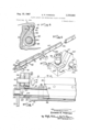
- FIGURE 1 is a general perspective view of a cylinder having a plate lockup mechanism constructed in accordance with the invention
- FIG. 1a is a horizontal fragmentary section, foreshortened, taken along line 1a1a in FIG. 1;
- FIG. 2 is a typical fragmentary transverse section taken along line 22 in FIG. 1;
- FIG. 3 is a fragmentary section looking along the line 3-3 in FIG. 1a;
- FIG. 4 is a fragment showing one of the jaw assemblies retracted, and with the jaws spread apart, for insertion or removal of the edge of a printing plate;
- FIG. 5 is a fragmentary perspective showing alined jaw assemblies
- FIG. 6 is a fragmentary perspective showing a pair of clamping jaw actuators for one edge of the plate with means for positionally adjusting them to effect peripheral register when in leading edge position;
- FIG. 7 is a fragmentary section taken along line 77 in FIG. 3;
- FIG. 8 is a transverse fragmentary section similar to FIG. 2, but taken through the jaw assemblies in the inner plate position looking along line 8-8 in FIG. 1;
- FIG. 9 is a section similar to FIG. 3 but showing the actuators for the jaw assemblies in the inner plate position taken along line 9-9 in FIG. 1a.
- FIG. 1 shows a reversible cylinder 10 having a shaft 11 and a driving gear 12.
- the cylinder is intended for use with thin printing plates P, the leading and trailing edges of which are inwardly bent to facilitate gripping.
- the cylinder shown is intended to mount the plates one around, i.e., with a single plate extending around nearly the entire periphery of the cylinder and either two plates or four plates across, extending the length of the cylinder. It is convenient to speak of the cylinder 10 as having four plate positions" 21, 22, 23, 24, positions 21, 24 being referred to as the outer positions and positions 22, 23 as the inner positions.
- the lockup operating mechanism indicated generally at 25, services positions 21, 22 which extend half way along the length of the cylinder and the mechanism 26, services positions 23, 24 which extend the remaining length of the cylinder, being accessible from the opposite end.
- the mechanism 25 is recessed in a groove 30 which extends longitudinally in the surface of the cylinder and which has, seated therein, filler pieces 31, 32, each held in place by a series of cap screws 33, 34 received in angled holes 35, 36.
- the filler pieces are contoured to provide an outwardly converging space 37 in which the jaw assemblies are recessed.
- first jaw assembly 40 made up of cooperating jaw members consisting of main or rigid jaw member 41 and sprung or flexible jaw member 42.
- the member 41 is formed at its ends with integral trunnions 43, 44 which are received in bearing blocks 45, 46, the latter being suitably secured, as by screws, in the groove 30.
- the main jaw 41 is, as shown, an elongated, rigid member of convergent or teardrop profile; terminating in a narrow upper edge presenting a flat clamping face 47.
- the cooperating sprung jaw 42 is in the form of series of specially formed springs which are secured, along their lower edges, to the lower part of main jaw 41 by screws 48 and with the upper edge presenting a flat face 49 which is biased against the face 47 on the main jaw.
- the trunnions 43, 44 support jaw assembly 40 for limited rotation to accomplish the gripping or releasing actions to be described.
- a jaw actuator 60 (FIG. 3) is provided at the outer end of the main jaw 41, being preferably keyed to trunnion 43 by a key 61 and having an engaging surface 62 as well as a knob or extension 63 fora purpose to be described.
- a series of jaw spreading stops 65 are provided in the path of movement of the sprung jaw 42.
- the stops 65 which are in the form of studs screwed or pressed into the filler member 31, are received in registering clearance openings 66 at spaced intervals. in the upper portion of the main jaw 41.
- a position adjusting member is provided selectively engageable with the extension 63 on the actuator 60'.
- This holding and position adjusting member, indicated at 70, is in the form of a yoke 71 having a recess 72 and a threaded shank 73.
- the shank is engaged by a special nut 74 which is captive in the eye portion of an eye bolt 75.
- the eye bolt is rotatably supported on a threaded shank 76 which extendsv through mounting plate 77 fixed to the end of the cylinder and is held in place by a nut 78 fixed on the shank by pin 79.
- the jaw 41 With the yoke 71 in engagement with the actuator knob 63, as shown, the jaw 41 will be held in a fixed position.
- rotation of the captive nut 74 moves the yoke upwardly or downwardly thereby slightly rotating the actuator 60 and the connected jaw assembly 40 through a small are as necessary to position the leading edge of the printing plate in precise peripheral register.
- a second jaw assembly with its associated holding and adjusting means is provided for the opposite edge of the plate, with all of the parts being substantially identical to, but a mirror image of, the parts previously described so that the same mechanism is employed, either in a leading edge mode or in a trailing edge mode, depending upon the direction of cylinder rotation. Since the assemblies are completely symmetrical about a central plane, indicated at 80 in FIG. 3, and identical in capability, there is no need to describe the second assembly in detail and it will suflice to say that similar parts on the right hand side of the plane are identified by similar reference numerals with the addition of subscript a.
- a throw off member is centered between and alined with, the actuators 60, 60a respectively (see FIG. 3), and movable from a central or neutral position selectively into engagement with either of the actuators 60, 60a for rotation of the jaw assemblies to open the jaws at one edge of the plate or the other.
- the throw off member, indicated at 90 is. of symmetrical shape, pivoted on a pin 91 which lies in the central plane 80 and having cam surfaces 92, 92a which engage the surfaces 62, 62a formed on the actuators.
- the throw off member has a rectangular upper end or shank 93 which may be engaged by an appropriate tool for rocking either in one direction or the other.
- the cylinder 10 is to be rotated clockwise so that the jaw assembly 40 is in the leading position.
- the first part of the operation is to swing the positioning yoke 71 temporarily clear of the actuator 60.
- the throw olf member 90 is then rotated clockwise to open the leading edge jaw assembly 40' thus permitting insertion of the leading edge of the plate.
- the throw olf member 90 is rocked back to its central or neutral position and actuator 60 rotates clockwise under influence of springs 50.
- the relative retreating of the stops 65 permits the sprung jaw 42 to return into clamping engagement and to grip the leading edge of the plate.
- the throw off member 90 For the purpose of clamping the trailing edge of the plate and holding it under spring tension, the throw off member 90 is rotated in the counterclockwise direction so that the cam surface 92a thereon engages the surface 62a on the actuator 60a, thus rotating jaw assembly 40a and opening the jaws permitting the trailing edge of the plate to be dropped in place. Following this the throw off member 90 is restored to its neutral position accompanied by counterclockwise rocking of the jaw assembly 40a. The initial portion of the restoring movement, by reason of the relative retreating movement of the stops 65a, per- Inits the jaw surfaces to come together thereby securely gripping the trailing edge of the plate and the tensioning springs 50a then take over to apply tension at the trailing edge of the plate. Thus, the plate is drawn snugly about the periphery of the plate cylinder.
- means are provided for simultaneously holding and positioning the jaw assemblies in the adjacent, inner plate position 22 to provide peripheral register along the entire length of a plate extending half the length the plate cylinder, i.e., where plates are employed two across.
- FIGS. 1a, 5, 7, 8 and 9 it will be seen that jaw assemblies are employed in the inner position which correspond, in all structural respects, to those in the outer position, and accordingly the same reference numerals plus 100 have been employed to designate corresponding parts.
- the positioning yokes 71, 71a which hold jaws fixed in adjusted peripheral register, are sufficiently wide, as shown in FIG. 6, as to span, or engage, both inner and outer actuators in leading edge position, in the present instance, the actuators 60, 160 respectively.
- the yoke 71 is swung clear of the actuators so, 160 and, instead, the opposite yoke 71a is swung into positioning engagement with the actuators 60a, 1690.
- means are provided for effecting axial register of jaw assemblies for both the inner and outer plate positions by moving the jaw assemblies, which are in alinement with one another, in unison.
- the leading edge of a plate extending half the length of the cylinder is acted upon as a unit in spite of the fact that separate jaw assemblies extend over only half of such plate.
- the operating shaft from the jaw assembly in the inner plate position is extended to a position outside of the actuators where it is engaged by a threaded adjusting member.
- the two axially adjacent jaw assemblies are held together as a unit and movement of the operating shaft is effective to move both of the jaw assemblies in the same direction and by precisely the same amount.
- the sleeve 210 engages a shoulder on the shaft and is held captive by a washer 212 and screw 213. Movement of the jaw assemblies 40, 140 in the outward direction is accomplished by turning adjusting sleeve 210 in one direction to create force against washer 212 to move the shaft which moves inner jaw 140, washer 205 and outer jaw 46.
- rocking of the throw off members 90, 190 in the clockwise direction opens the jaws and permits entry of the leading edge of the plate, following which the throw off members are restored to central, inactive positions.
- This re sults in positive gripping of the leading edge and, if desired, the surfaces 47, 49 may be roughened or knurled to enhance the gripping action.
- the yoke 71 of the adjusting mechanism 70 is swung into engagement with knobs 63 and 163 on both of the actuators 60, and the nut 74 is rotated, if necessary, in one direction or the other.
- the adjusting sleeve 21% is rotated.
- the pitch of the sleeve is suifi ciently shallow so that ordinary friction is sufficient to maintain the adjustment.
- the throw off members 96 are rocked counterclockwise, resulting in separation of related jaws and enabling the trailing edge to be inserted into the jaw assemblies 40a, 140a.
- the throw off members are then restored to their central inactive position resulting in gripping action by the jaws and so that the tensioning springs at the trailing edge take over to tension the plate.
- any lack of firm seating of the plate on the cylinder is taken care of automatically during the first rotation of the plate cylinder because of the ironing effect of the cooperating impression cylinder, and the tensioning springs 50a are effective during running of the press to maintain the plate under constant tension, so that it remains in close contact with the cylinder surface.
- Both of the registering adjustments discussed immediately above will ordinarily be of a preliminary or approximate nature and final registering adjustment may be made after trial run.
- the throw off members 98, 190 are rocked to remove the tension on the plate and to free the trailing edge.
- the registering adjustments may then be touched up as neces sary and the throw off members may be restored to neutral position to reclamp and tension the trailing edge.
- Lockup may be completed within a shorter time than that required for more conventional designs, whether reversible or unidirectional.
- the mechanism may be employed with equal advantage for back plates which are normally of single page widths and thus four across, in which case precise individual registering adjustment is not necessary.
- the leading edges of both of the plates may be clamped simultaneously by rocking the throw off members 90, 190 as described, following which the leading edges are locked in position by engagement of the yoke 70 or 70 6!, whichever is in leading edge position.
- the trailing edges are then engaged by rocking the throw off members 90, 190 in the opposite direction, and then restored to the neutral or inactive position for normal running. It may be noted that since two throw off members are provided, one for each plate position, the plates in either one of the two positions, 21, 22 may be removed and replaced without disturbing the position of the companion plate.
- the lockup is not only simple to operate, it is compactly and inexpensively constructed, and the reversible feature can be added to lithographic presses having provision for driving plate cylinders in either direction. Moreover, while the advantages of the device are particularly apparent when it is used in a reversible cylinder, it is not 7 limited to such use and structure of the type disclosed and claimed but may be used universally in cylinders whether intended for reversible or unidirectional operation.
- a plate lock up mechanism comprising, in combination, inner and outer pairs of jaw assemblies extending longitudinally in recessed position in the cylinder for gripping the leading and trailing edges of a printing plate, each of said jaw assemblies having a pair of opposed jaws biased together and each of the assemblies having a series of springs bearing thereagainst tending to urge jaw assembly in a direction to tension the plate, each of the inner jaw assemblies having an operating shaft extending through an opening in the alined outer jaw assembly, actuators at the outboard end of the jaw assemblies and connected to the ends of the outer jaw assemblies and to the ends of the ope-rating shafts for the inner jaw assemblies for retracting the respective jaw assemblies against the force of their associated tensioning springs, means for separating the opposed jaws for entry or removal of the adjacent edge of the printing plate, inner throw off means associated with the actuators for the inner jaw assemblies, outer throw off means associated with the actuators for the outer jaw assemblies, and position fixing means at the outboard end of
- a plate lock up mechanism comprising, in combination, inner and outer pairs of jaw assemblies extending longitudinally in recessed position in the cylinder for gripping the leading and trailing edges of a printing plate, each of said jaw assemblies having a pair of opposed jaws biased together and each of the jaws having a series of tensioning springs bearing thereagainst tending to urge the jaw assembly in a direction to tension the plate, each of the inner jaw assemblies having an operating shaft extending through an opening in the adjacent outer jaw assembly, actuators connected to the ends of the outer jaw assemblies and to the ends of the operating shafts for the inner jaw assemblies for retracting the respective jaw assemblies against the force of their associated tensioning springs, means operated toward the end of the retracting movement for separating the opposed jaws for entry of the adjacent edge of the printing plate, an inner throw oif member symmetrically positioned between the actuators for the inner jaw assemblies and an outer throw ofi member symmetrically positioned between the actuators for the outer jaw assemblies, each of these throw
- a plate lock up mechanism comprising, in combination, inner and outer pairs of jaw assemblies extending longitudinally in the cylinder in recessed position for gripping of the opposite edges of a printing plate, each of said jaw assemblies being formed of cooperating jaws biased together and each of said jaw assemblies having a series of tensioning springs anchored with respect to the cylinder for biasing the jaw assemblies in a plate tensioning direction, the jaw assemblies in the inner position having operating shafts extending to the end of the cylinder through openings in the jaw assemblies in outer position, actuators at the outboard end of the jaw assemblies and coupled to the outer jaw assemblies and to the shafts from the inner jaw assemblies for rotating the respective jaw assemblies against the force of the biasing springs, throw-oft means for moving the actuators, means for separating the opposed jaws for entry of the adjacent edge of the plate, and adjustable yoke means at the outboard end of the jaw assemblies for selectively engaging both of the actuators at the leading edge position for positioning the jaw assemblies at the leading edge
- a plate lock up mechanism comprising, in combination, inner and outer pairs of jaw assemblies extending longitudinally in recessed position in the cylinder for gripping the opposite edges of a printing plate, each of said jaw assemblies being formed of a pair of cooperative jaws biased together, at least one of said jaw assemblies in each pair having a series of tensioning springs anchored with respect to the cylinder and tending to move the jaw assembly in a direction to tension the plate, the jaw assemblies in the inner position having shafts extending through the jaw assemblies in outer position, actuators at the outboard ends of the outer jaw assemblies and at the outboard end-s of the shafts leading to the inner jaw assemblies for retracting the assemblies against the force of their tensioning springs, means for separating the opposed jaws for entry of the adjacent edge of the plate, throw off means movable into engagement with the actuators for accomplishing entry of the edges of the plate, adjusting means at the outboard end of the jaw assemblies and selectively enga-geable with the actuators at the
- a plate lock up mechanism comprising, in combination, a pair of closely adjacent opposed jaw assemblies extending longitudinally side by side in recessed position in the cylinder for gripping the opposite edges of a printing plate, said jaw assemblies being mounted for movement within the recess relative to the cylinder, each of said jaw assemblies being formed of a pair of cooperating jaws biased together, a series of tensioning springs anchored with respect to the cylinder and tending to move each jaw assembly in a direction to tension the plate, an actuator at the outboard end of each of the jaw assemblies for retracting the assemblies against the force of their tensioning springs, means for separating the opposed jaws for entry of the adjacent edge of the plate, throw oif means movable into engagement with the actuators for pivoting said jaws into positions for receiving of the edges of the plate, adjusting means at the outboard end of the jaw assemblies and selectively engageable with the actuator at the leading edge of the plate for positively positioning the plate for peripheral register, and additional means at the outboard
- a plate lock up mechanism comprising, in combination, first and second jaw assemblies extending longitudinally side by side in recessed position in the cylinder and each having a rigid jaw and a flexible jaw, in gripping engagement, a series of springs bottomed with respect to the cylinder and pressing against the rigid jaws tending to move the latter in a plate-tensioning direction, actuators at the outboard ends of the rigid jaws for rotating said assemblies in the face of the force exerted by the tensioning springs, throw off means for engaging the actuators, each of the rigid jaws being in the form of a rigid member of tear drop cross section having an upper end presenting a jaw face and each of the flexible jaws being in the form of a thin, flat spring secured to the rigid jaw and preloaded against the jaw face, jaw spreading stops secured to the cylinder to intercept and limit the movement of the flexible jaw as the jaw assembly is rocked in the retracting direction so that the jaws are spread apart for entry of the
- a plate lock up mechanism comprising, in combination, first and second jaw assemblies extending longitudinally in the cylinder in recessed position, each of the jaw assemblies being formed of a pair of cooperating jaws biased together and having tensioning springs anchored to the cylinder tending to move the jaw assembly in a platetensioning direction, actuators secured to the outer ends of the jaw assemblies, throw off means for moving the actuators, first and second adjusting means for positively positioning the actuators for peripheral register of the plate, each adjusting means being individually disengageable from its associated actuator to permit the jaw assembly at the trailing edge to move under the influence of its tensioning springs for tensioning the plate while the leading edge is held in position and control means operatively associated with said jaw assemblies for setting each jaw assembly in either a leading edge mode, for clamping the leading edge of a printing plate carried by the cylinder in a fixed position when the reversible cylinder is rotated in one direction, or a trailing edge mode, for clamping the trailing edge of
- a plate clamping mechanism for securing a flexible printing plate to the plate cylinder of a printing press
- the combination comprising a rigid longitudinally extending jaw member supported in the cylinder for limited rocking movement and having a body which tapers to a relatively thin outer edge at the surface of the cylinder defining a lateral face, a thin flat spring member secured to the body of the rigid member in conforming relation and having an outer edge defining a lateral face which bears flatly against the face of the rigid member, said spring member being preloaded against the rigid member, a plurality of stops in said cylinder adjacent the outer edge of the rigid member and on the opposite side of said rigid member from said lateral face, the rigid member being formed with clearance openings for said stops with said stops located to project through said openings from said opposite side of said rigid member when the rigid member is rotated in the direction of the stops whereby the stops engage the spring member resulting in separation of the faces on the rigid member and spring member for insertion and removal of the plate.
- a plate clamping mechanism for securing a flexible printing plate to the plate cylinder of a printing press, the combination comprising a rigid longitudinally extending jaw member recessed in a longitudinal groove formed in the cylinder and mounted therein for limited rocking movement, said rigid jaw member having a body which tapers to a relatively thin outer edge having a lateral face, a thin fiat spring member secured to the body of the rigid member adjacent the axis of rotation and having an outer edge defining a lateral face which bears flatly against the face of the rigid member, said spring member being preloaded against the rigid member for clamping the edge of the printing plate therebetween, means for forcibly separating the faces of the spring member and rigid member in response to rocking of the rigid member, means for adjusting the angular position of the rigid member thereby to adjust the peripheral register of the engaged plate, and means at the opposite end of the engaged plate for applying tension thereto so that the plate conforms to the surface of the cylinder.
- a plate clamping mechanism for securing a flexible printing plate to the plate cylinder of a printing press
- the combination comprising a rigid longitudinally extending jaw member recessed in a longitudinal groove formed in the cylinder and mounted therein for limited rocking movement, said rigid jaw member having a body which tapers to a relatively thin outer edge having a lateral face, a thin flat spring member secured to the body of the rigid member adjacent the axis of rotation and having an outer edge defining a lateral face which bears flatly against the face of the rigid member, said spring member being preloaded against'the rigid member for clamping the edge of the printing plate therebetween, means for forcibly separating the faces of the spring member and rigid member incident to rocking of the rigid member, means for adjusting the angular position of the rigid member thereby to adjust the peripheral register of the engaged plate, means at the opposite end of the engaged plate for applying tension thereto so that the plate conforms to the surface of the cylinder, and means for effecting bodily endwise adjustment of the rigid member for adjusting the axial
- An improved plate lock up mechanism suitable for use in a reversible plate cylinder in a continuous web-fed printing press, said lock up mechanism. comprising the combination of first and second longitudinally extending, closely adjacent jaw assemblies recessed. in the cylinder with each jaw assembly gripping one of the opposite edges of a printing plate, said jaw assemblies being mounted for movement within the recess relative to the cylinder so as to move the plate gripped by the jaw assemblies in a circumferential direction, said jaw assemblies being mirror images of one another and symmetrical with respect to a central plane passing through the axis of the cylinder, biasing means disposed between said cylinder and each of said jaw assemblies to urge each assembly in a platetensioning direction and locking elements mounted on the cylinder and each jaw assembly, respectively, and movable into locking engagement for holding the jaw assembly in a fixed position, and control :means operatively associated with said jaw assemblies for selectively actuating said locking elements to set each jaw assembly in either a leading edge mode, for clamping the leading edge of a printing plate carried by the cylinder
- An improved plate lock up mechanism as defined in claim 11 which includes adjustable positioning means associated with said locking elements on said cylinder and each of said jaw assemblies for accurately positioning the plate for peripheral register.
- An improved plate lock up mechanism as defined in claim 11 in which each of said jaw assemblies is mounted for axial movement and which includes adjustable positioning means associated with each of said jaw assemblies for accurately positioning the plate for axial register.
Landscapes
- Engineering & Computer Science (AREA)
- Mechanical Engineering (AREA)
- Supply, Installation And Extraction Of Printed Sheets Or Plates (AREA)
Description
1.967 E. R. HARENZA 3,335,663
PLATE LOCKUP FOR REVERSIBLE PLATE CYLINDER Filed Aug. 12, 1964 3 Sheets-Sheet 1 L EDWARD KHARENZA I I y-' %Mm4,1 J@.
U Y 'WEYW Aug. 15, 1967 E. R. HARENZA PLATE LOCKUP FOR REVERSIBLE PLATE CYLINDER 3 Sheets-Sheet f? Filed Aug. 12, 1964 Aug. 15, 1967 E. R. HARENZA 3,335,663 PLATE LOCKUP FOR REVERSIBLE PLATE CYLINDER Filed Aug. 12, 1964 3 Sheets-Sheet rovamrr ow Eownno R, HARENZA TToms w United States Patent M 3,335,663 PLATE LOCIKUP FOR REVERSIBLE PLATE CYLINDER Edward R. Harenza, Chicago, Ill., assignor to Miehle- Goss-Dexter, Incorporated, Chicago, 111., a corporation of Delaware Filed Aug. 12, 1964, Ser. No. 388,989 13 Ciaims. (Cl. 101-4151) The present invention relates to printing presses and more particularly to means for securing and registering thin printing plates on a cylinder driven in either direction.
In a printing press intended for printing colors, or in a newspaper press unit which has been adapted for printing colors, the web lead, i.e., the path which the web follows around the cylinders, may be changed depending upon the result to be accomplished, for example, whether printing is to take place on only one side or on both sides of the web. This requires certain of the press cylinders to be reversible, capable of rotating in either direction at the choice of the operator. Where a plate is held on the cylinder undertension, good practice requires that the leading edge of the place be held in a fixed position with tension Springs active only at the trailing edge.
It is an object of the present invention to provide an improved plate lockup for a reversible plate cylinder which provides adjustment or register of the leading edge of the plate and tensioning of the trailing edge for both directions of rotation. It is another object to provide a lockup for printing plates on a reversible cylinder where a similar mechanism is provided at both the leading and trailing edges, and which has provision for easy switching of the mechanism from the leading edge mode to the trailing edge mode with no possibility of confusion on the part of the operator. In this connection, it is an object to provide a plate lockup for a reversible cylinder which is simple to operate, having provision for quick and easy throw-01f for removal and insertion of plates, and in which the throw-off and change of mode may be effected by light operating forces while, nevertheless, providing positive gripping at both the leading and trail ing edges of the plate. It is, therefore, an object to provide a plate lockup which is safe and reliable in operation and which may be operated at modern day high speeds without risk of dislodgement.
Another object of the present invention is to provide a plate lockup for a reversible cylinder which is versatile and which may be employed for either color or black plates arranged two across or four across the length of the cylinder and which permits individual plates to be replaced without disturbing the position of the remaining plates.
Still another object of the present invention is to provide a plate lockup for a reversible cylinder which includes a novel means for eflfecting peripheral and axial adjustment of a printing plate at the leading edge position regardless of direction of rotation.
Finally, it is an object of the invention to provide a plate lockup which is of simple construction, compact, inherently strong, and free of maintenance problems and which is so economical that it may be used universally, even in cylinders where reversibility is not an operating requirement.
Other objects and advantages of the invention will become apparent upon reading the attached detailed description and upon reference to the drawings, in which:
FIGURE 1 is a general perspective view of a cylinder having a plate lockup mechanism constructed in accordance with the invention;
3,335,663 Patented Aug. 15, 1967 FIG. 1a is a horizontal fragmentary section, foreshortened, taken along line 1a1a in FIG. 1;
FIG. 2 is a typical fragmentary transverse section taken along line 22 in FIG. 1;
FIG. 3 is a fragmentary section looking along the line 3-3 in FIG. 1a;
FIG. 4 is a fragment showing one of the jaw assemblies retracted, and with the jaws spread apart, for insertion or removal of the edge of a printing plate;
FIG. 5 is a fragmentary perspective showing alined jaw assemblies;
FIG. 6 is a fragmentary perspective showing a pair of clamping jaw actuators for one edge of the plate with means for positionally adjusting them to effect peripheral register when in leading edge position;
FIG. 7 is a fragmentary section taken along line 77 in FIG. 3;
FIG. 8 is a transverse fragmentary section similar to FIG. 2, but taken through the jaw assemblies in the inner plate position looking along line 8-8 in FIG. 1;
FIG. 9 is a section similar to FIG. 3 but showing the actuators for the jaw assemblies in the inner plate position taken along line 9-9 in FIG. 1a.
While the invention has been described in connection with a preferred embodiment, it will be understood that I do not intend to be limited to the embodiment shown but intend to cover the various alternatives and equivalent constructions included within the spirit and scope of the appended claims.
Turning now to the drawings, FIG. 1 shows a reversible cylinder 10 having a shaft 11 and a driving gear 12. The cylinder is intended for use with thin printing plates P, the leading and trailing edges of which are inwardly bent to facilitate gripping. The cylinder shown is intended to mount the plates one around, i.e., with a single plate extending around nearly the entire periphery of the cylinder and either two plates or four plates across, extending the length of the cylinder. It is convenient to speak of the cylinder 10 as having four plate positions" 21, 22, 23, 24, positions 21, 24 being referred to as the outer positions and positions 22, 23 as the inner positions. The lockup operating mechanism, indicated generally at 25, services positions 21, 22 which extend half way along the length of the cylinder and the mechanism 26, services positions 23, 24 which extend the remaining length of the cylinder, being accessible from the opposite end. In the discussion which follows attention will be focused on the lockup mechanism 25 and the outer and inner plate positions 21, 22, it being understood that the mechanism 26 is a duplicate of mechanism 25.
The mechanism 25 is recessed in a groove 30 which extends longitudinally in the surface of the cylinder and which has, seated therein, filler pieces 31, 32, each held in place by a series of cap screws 33, 34 received in angled holes 35, 36. The filler pieces are contoured to provide an outwardly converging space 37 in which the jaw assemblies are recessed.
Extending in plate position 21 is a first jaw assembly 40 made up of cooperating jaw members consisting of main or rigid jaw member 41 and sprung or flexible jaw member 42. The member 41 is formed at its ends with integral trunnions 43, 44 which are received in bearing blocks 45, 46, the latter being suitably secured, as by screws, in the groove 30. The main jaw 41 is, as shown, an elongated, rigid member of convergent or teardrop profile; terminating in a narrow upper edge presenting a flat clamping face 47. The cooperating sprung jaw 42 is in the form of series of specially formed springs which are secured, along their lower edges, to the lower part of main jaw 41 by screws 48 and with the upper edge presenting a flat face 49 which is biased against the face 47 on the main jaw. The trunnions 43, 44 support jaw assembly 40 for limited rotation to accomplish the gripping or releasing actions to be described.
For biasing the jaw assembly 44) in a direction which tends to tension the plate, the assembly is provided with a series of coil springs 50 which are seated in recesses 51 in the body of the main jaw. As will be seen, only the springs at the trailing edge position are active to apply tension to the plate. For the purpose of bodily rocking the jaw assembly about its axis, for example, to retract the jaw assembly against the force of the springs 50', a jaw actuator 60 (FIG. 3) is provided at the outer end of the main jaw 41, being preferably keyed to trunnion 43 by a key 61 and having an engaging surface 62 as well as a knob or extension 63 fora purpose to be described.
To bring about automatic separation of the jaw surfaces 47, 49 when the main jaw 40 is rotated to the throw-off position, a series of jaw spreading stops 65 are provided in the path of movement of the sprung jaw 42. The stops 65, which are in the form of studs screwed or pressed into the filler member 31, are received in registering clearance openings 66 at spaced intervals. in the upper portion of the main jaw 41. It will be apparent, then, that as the actuator 60 is rocked in a counterclockwise direction, rotating the main jaw 41 counterclockwise as shown in FIG. 4, a point will be reached, before the end of the retraction movement, when the sprung jaw 42 engages stops preventing any further movement of the sprung jaw, while continued rotation of main jaw 41 separates the surfaces 47, 49 for insertion or removal of one edge of the plate. Return movement of the actuator, conversely, permits the jaw surfaces to resume gripping engagement. Cylinder is rotatable in either direction and therefore jaw assembly 40 may grip either the leading or the trailing edge of the plate in plate position 21. When it grips the leading edge, mechanism is provided to hold jaw assembly 40 in fixed position and when necessary, for adjusting the fixed position so that the plate held by the jaw 40 will register with other plates. When rotation is in the opposite direction, the jaw grips the trailing edge, the holding mechanism is not used and springs 50 are active to tension the plate.
For the purpose of positive positioning of the jaw assembly 40 during one direction of cylinder rotation for registering of the plate when such jaw assembly is in the leading edge position, a position adjusting member is provided selectively engageable with the extension 63 on the actuator 60'. This holding and position adjusting member, indicated at 70, is in the form of a yoke 71 having a recess 72 and a threaded shank 73. The shank is engaged by a special nut 74 which is captive in the eye portion of an eye bolt 75. The eye bolt is rotatably supported on a threaded shank 76 which extendsv through mounting plate 77 fixed to the end of the cylinder and is held in place by a nut 78 fixed on the shank by pin 79. Thus, with the yoke 71 in engagement with the actuator knob 63, as shown, the jaw 41 will be held in a fixed position. When adjustment is required, rotation of the captive nut 74 moves the yoke upwardly or downwardly thereby slightly rotating the actuator 60 and the connected jaw assembly 40 through a small are as necessary to position the leading edge of the printing plate in precise peripheral register.
In accordance with one of the important aspects of the present invention, a second jaw assembly with its associated holding and adjusting means is provided for the opposite edge of the plate, with all of the parts being substantially identical to, but a mirror image of, the parts previously described so that the same mechanism is employed, either in a leading edge mode or in a trailing edge mode, depending upon the direction of cylinder rotation. Since the assemblies are completely symmetrical about a central plane, indicated at 80 in FIG. 3, and identical in capability, there is no need to describe the second assembly in detail and it will suflice to say that similar parts on the right hand side of the plane are identified by similar reference numerals with the addition of subscript a. Further in accordance with the invention, a throw off member is centered between and alined with, the actuators 60, 60a respectively (see FIG. 3), and movable from a central or neutral position selectively into engagement with either of the actuators 60, 60a for rotation of the jaw assemblies to open the jaws at one edge of the plate or the other. In the present instance the throw off member, indicated at 90, is. of symmetrical shape, pivoted on a pin 91 which lies in the central plane 80 and having cam surfaces 92, 92a which engage the surfaces 62, 62a formed on the actuators. The throw off member has a rectangular upper end or shank 93 which may be engaged by an appropriate tool for rocking either in one direction or the other. When the throw off member 90 is rocked clockwise, the cam surface 92 thereon crowds against the surface 62- causing the actuator 60 to rock counterclockwise, thereby rocking the jaw assembly 40 in the counterclockwise or retract direction and when the sprung jaw 42 engages the stops 65 the jaws will separate upon further rotation of the assembly. The jaw assembly, 4011, is operated in similar fashion when the throw off member 90 is rocked in the opposite direction, causing the cam surface 92a thereon to crowd against the surface 62a on the actuator.
In picturing the operation of the device as thus far described, it may be assumed, by way of example, that the cylinder 10 is to be rotated clockwise so that the jaw assembly 40 is in the leading position. Under such circumstances the first part of the operation is to swing the positioning yoke 71 temporarily clear of the actuator 60. The throw olf member 90 is then rotated clockwise to open the leading edge jaw assembly 40' thus permitting insertion of the leading edge of the plate. Next the throw olf member 90 is rocked back to its central or neutral position and actuator 60 rotates clockwise under influence of springs 50. During the initial portion of the restoring movement the relative retreating of the stops 65, permits the sprung jaw 42 to return into clamping engagement and to grip the leading edge of the plate. Subsequently, as the extension 63 on the actuator 60 rotates into a position of register with the yoke 71, by turning nut 78, the yoke is swung into engaging position. Once the actuator is engaged by the yoke, further rotation of jaw assembly is prevented and the tensionin g springs perform no further function since jaw assembly 40 holds the leading edge of the plate in fixed position. The yoke adjusting nut 74 may then be turned, if necessary, until the leading edge of the plate is at a reference position, or registers with plates on other plate cylinders of the press.
For the purpose of clamping the trailing edge of the plate and holding it under spring tension, the throw off member 90 is rotated in the counterclockwise direction so that the cam surface 92a thereon engages the surface 62a on the actuator 60a, thus rotating jaw assembly 40a and opening the jaws permitting the trailing edge of the plate to be dropped in place. Following this the throw off member 90 is restored to its neutral position accompanied by counterclockwise rocking of the jaw assembly 40a. The initial portion of the restoring movement, by reason of the relative retreating movement of the stops 65a, per- Inits the jaw surfaces to come together thereby securely gripping the trailing edge of the plate and the tensioning springs 50a then take over to apply tension at the trailing edge of the plate. Thus, the plate is drawn snugly about the periphery of the plate cylinder.
In accordance with one of the aspects of the present invention, means are provided for simultaneously holding and positioning the jaw assemblies in the adjacent, inner plate position 22 to provide peripheral register along the entire length of a plate extending half the length the plate cylinder, i.e., where plates are employed two across. Referring to FIGS. 1a, 5, 7, 8 and 9, it will be seen that jaw assemblies are employed in the inner position which correspond, in all structural respects, to those in the outer position, and accordingly the same reference numerals plus 100 have been employed to designate corresponding parts. For the purpose of retracting, or controlling the position of the main jaws indicated at 141, 141a, they are provided with operating shafts 201, 201a secured to the main jaws by pins 202, 202a, the operating shafts extending through openings 203, 203a formed in the main jaws of the outer set, to the outside of the cylinder. The outer ends of the operating shafts 5261, 201a are pinned to actuators 160, 160a by pins 161, 1610. Centrally pivoted between the actuators 160, 160a is a throw off member 190 having surfaces 192, 192a for crowding engagement with, and rocking of, the actuators 160, 169a, just as described in connection with the jaw mechanisms in the outer position.
To insure that the jaw assemblies at the leading edge position are positioned in unison with one another and are at all times in perfect alinement, it is one of the important features of the present invention that the positioning yokes 71, 71a which hold jaws fixed in adjusted peripheral register, are sufficiently wide, as shown in FIG. 6, as to span, or engage, both inner and outer actuators in leading edge position, in the present instance, the actuators 60, 160 respectively. When the direction of cylinder rotation is reversed, the yoke 71 is swung clear of the actuators so, 160 and, instead, the opposite yoke 71a is swung into positioning engagement with the actuators 60a, 1690.
In accordance with one of the aspects of the present invention, means are provided for effecting axial register of jaw assemblies for both the inner and outer plate positions by moving the jaw assemblies, which are in alinement with one another, in unison. As a result, the leading edge of a plate extending half the length of the cylinder is acted upon as a unit in spite of the fact that separate jaw assemblies extend over only half of such plate. To effect the endwise movement, and as shown in FIG. 7 and FIG. 1a, the operating shaft from the jaw assembly in the inner plate position is extended to a position outside of the actuators where it is engaged by a threaded adjusting member. The two axially adjacent jaw assemblies are held together as a unit and movement of the operating shaft is effective to move both of the jaw assemblies in the same direction and by precisely the same amount. To propel the shaft 201 endwise, it is provided at its end with a hollow threaded sleeve 210 which is threaded into the mounting plate 77 and fits snugly around an extension 211 on the shaft. The sleeve 210 engages a shoulder on the shaft and is held captive by a washer 212 and screw 213. Movement of the jaw assemblies 40, 140 in the outward direction is accomplished by turning adjusting sleeve 210 in one direction to create force against washer 212 to move the shaft which moves inner jaw 140, washer 205 and outer jaw 46. When turned in the opposite direction the sleeve bears against shaft 201, moving it, actuator 16ft, washer 2G6 and outer jaw 40 inwardly as a unit. The hearing blocks 45 and 46 provide a sliding fit which permits the endwise movement required for adjustment. Identical means are provided for effecting axial adjustment of the adjacent set of jaw assemblies 4th: and 14011, corresponding parts being identified by the same reference numerals with the addition of the letter subscript.
It will be apparent to one skilled in the art that l have provided a plate lockup mechanism which is ideally suited for plate cylinders capable of reversible rotation. Since the mechanisms provided at the respective edges of the plate are mirror images of one another, the device operates with equal effectiveness in both directions of rotation. Regardless of direction, the leading edge of the plate is securely clamped and held in adjusted peripheral position yet is capable of both axial and peripheral register adjustment, while the trailing edge is also securely clamped but maintained under floating tension.
For example, where clockwise rotation is required for a color plate spanning plate positions 21, 22, so that the jaw assemblies 40, are in leading edge position, rocking of the throw off members 90, 190 in the clockwise direction opens the jaws and permits entry of the leading edge of the plate, following which the throw off members are restored to central, inactive positions. This re sults in positive gripping of the leading edge and, if desired, the surfaces 47, 49 may be roughened or knurled to enhance the gripping action. For peripheral register the yoke 71 of the adjusting mechanism 70 is swung into engagement with knobs 63 and 163 on both of the actuators 60, and the nut 74 is rotated, if necessary, in one direction or the other. For axial register the adjusting sleeve 21% is rotated. The pitch of the sleeve is suifi ciently shallow so that ordinary friction is sufficient to maintain the adjustment. To clamp the trailing edge of the plate, the throw off members 96, are rocked counterclockwise, resulting in separation of related jaws and enabling the trailing edge to be inserted into the jaw assemblies 40a, 140a. The throw off members are then restored to their central inactive position resulting in gripping action by the jaws and so that the tensioning springs at the trailing edge take over to tension the plate. After the plate has been locked up, any lack of firm seating of the plate on the cylinder is taken care of automatically during the first rotation of the plate cylinder because of the ironing effect of the cooperating impression cylinder, and the tensioning springs 50a are effective during running of the press to maintain the plate under constant tension, so that it remains in close contact with the cylinder surface.
Both of the registering adjustments discussed immediately above will ordinarily be of a preliminary or approximate nature and final registering adjustment may be made after trial run. For the final adjustment, the throw off members 98, 190 are rocked to remove the tension on the plate and to free the trailing edge. The registering adjustments may then be touched up as neces sary and the throw off members may be restored to neutral position to reclamp and tension the trailing edge.
For the opposite direction of rotation this procedure is the same except for the fact that the register adjusting mechanism 70a is swung into active position and the mechanism 70 is swung into a retracted or inactive position by rotating the nut 78 on the eye bolt. The throw off sequence is simply reversed, with the jaw assemblies 40a, Mlba being operated first to clamp the leading edge.
Operating forces are light and the entire adjusting procedure is extremely simple, oifering no chance of confusion or mistake. Lockup may be completed within a shorter time than that required for more conventional designs, whether reversible or unidirectional.
The mechanism may be employed with equal advantage for back plates which are normally of single page widths and thus four across, in which case precise individual registering adjustment is not necessary. The leading edges of both of the plates may be clamped simultaneously by rocking the throw off members 90, 190 as described, following which the leading edges are locked in position by engagement of the yoke 70 or 70 6!, whichever is in leading edge position. The trailing edges are then engaged by rocking the throw off members 90, 190 in the opposite direction, and then restored to the neutral or inactive position for normal running. It may be noted that since two throw off members are provided, one for each plate position, the plates in either one of the two positions, 21, 22 may be removed and replaced without disturbing the position of the companion plate.
The lockup is not only simple to operate, it is compactly and inexpensively constructed, and the reversible feature can be added to lithographic presses having provision for driving plate cylinders in either direction. Moreover, while the advantages of the device are particularly apparent when it is used in a reversible cylinder, it is not 7 limited to such use and structure of the type disclosed and claimed but may be used universally in cylinders whether intended for reversible or unidirectional operation.
In the present design stresses are equalized along the leading and trailing edges so that no localized stresses are set up which might, after many revolutions, result in incipient failure or fatigue. This, combined with the positive gripping action, which always remains the same and is not subject to control by the press operator, insures retention of even relatively fragile plates during extended high speed operation.
I claim as my invention:
1. In a plate cylinder for a continuous web-fed printing press, a plate lock up mechanism comprising, in combination, inner and outer pairs of jaw assemblies extending longitudinally in recessed position in the cylinder for gripping the leading and trailing edges of a printing plate, each of said jaw assemblies having a pair of opposed jaws biased together and each of the assemblies having a series of springs bearing thereagainst tending to urge jaw assembly in a direction to tension the plate, each of the inner jaw assemblies having an operating shaft extending through an opening in the alined outer jaw assembly, actuators at the outboard end of the jaw assemblies and connected to the ends of the outer jaw assemblies and to the ends of the ope-rating shafts for the inner jaw assemblies for retracting the respective jaw assemblies against the force of their associated tensioning springs, means for separating the opposed jaws for entry or removal of the adjacent edge of the printing plate, inner throw off means associated with the actuators for the inner jaw assemblies, outer throw off means associated with the actuators for the outer jaw assemblies, and position fixing means at the outboard end of the jaw assemblies and selectively engageable with both of the actuators associated with the leading edge of the plate for adjusting the leading edge for peripheral register of the plate while leaving the actuators at the training edge free in order to tension the plate in response to the force exerted by the springs at the trailing edge.
2. In a reversible plate cylinder for a printing press, a plate lock up mechanism comprising, in combination, inner and outer pairs of jaw assemblies extending longitudinally in recessed position in the cylinder for gripping the leading and trailing edges of a printing plate, each of said jaw assemblies having a pair of opposed jaws biased together and each of the jaws having a series of tensioning springs bearing thereagainst tending to urge the jaw assembly in a direction to tension the plate, each of the inner jaw assemblies having an operating shaft extending through an opening in the adjacent outer jaw assembly, actuators connected to the ends of the outer jaw assemblies and to the ends of the operating shafts for the inner jaw assemblies for retracting the respective jaw assemblies against the force of their associated tensioning springs, means operated toward the end of the retracting movement for separating the opposed jaws for entry of the adjacent edge of the printing plate, an inner throw oif member symmetrically positioned between the actuators for the inner jaw assemblies and an outer throw ofi member symmetrically positioned between the actuators for the outer jaw assemblies, each of these throw off members being movable in opposite directions from a central position for operating its respective actuator, and position adjusting means selectively engageable with the actuators associated with the leading edge of the plate for peripherally registering the leading edge while leaving the actuators at the trailing edge free to undergo takeup movement in response to the force exerted by the tensioning springs at the trailing edge.
3. In a plate cylinder for a continuous web-fed printing press, a plate lock up mechanism comprising, in combination, inner and outer pairs of jaw assemblies extending longitudinally in the cylinder in recessed position for gripping of the opposite edges of a printing plate, each of said jaw assemblies being formed of cooperating jaws biased together and each of said jaw assemblies having a series of tensioning springs anchored with respect to the cylinder for biasing the jaw assemblies in a plate tensioning direction, the jaw assemblies in the inner position having operating shafts extending to the end of the cylinder through openings in the jaw assemblies in outer position, actuators at the outboard end of the jaw assemblies and coupled to the outer jaw assemblies and to the shafts from the inner jaw assemblies for rotating the respective jaw assemblies against the force of the biasing springs, throw-oft means for moving the actuators, means for separating the opposed jaws for entry of the adjacent edge of the plate, and adjustable yoke means at the outboard end of the jaw assemblies for selectively engaging both of the actuators at the leading edge position for positioning the jaw assemblies at the leading edge in alinement for peripheral register of the printing plate.
4. In a plate cylinder for a continuous web-fed printing press, a plate lock up mechanism comprising, in combination, inner and outer pairs of jaw assemblies extending longitudinally in recessed position in the cylinder for gripping the opposite edges of a printing plate, each of said jaw assemblies being formed of a pair of cooperative jaws biased together, at least one of said jaw assemblies in each pair having a series of tensioning springs anchored with respect to the cylinder and tending to move the jaw assembly in a direction to tension the plate, the jaw assemblies in the inner position having shafts extending through the jaw assemblies in outer position, actuators at the outboard ends of the outer jaw assemblies and at the outboard end-s of the shafts leading to the inner jaw assemblies for retracting the assemblies against the force of their tensioning springs, means for separating the opposed jaws for entry of the adjacent edge of the plate, throw off means movable into engagement with the actuators for accomplishing entry of the edges of the plate, adjusting means at the outboard end of the jaw assemblies and selectively enga-geable with the actuators at the leading edge of the plate for positively positioning the leading edge for peripheral register, and axial adjusting means at the outboard end of the jaw assemblies for bodily adjusting respectively in unison the jaw assemblies at the leading edges of the plate for effecting axial register.
5. In a plate cylinder for a continuous web-fed printing press, a plate lock up mechanism comprising, in combination, a pair of closely adjacent opposed jaw assemblies extending longitudinally side by side in recessed position in the cylinder for gripping the opposite edges of a printing plate, said jaw assemblies being mounted for movement within the recess relative to the cylinder, each of said jaw assemblies being formed of a pair of cooperating jaws biased together, a series of tensioning springs anchored with respect to the cylinder and tending to move each jaw assembly in a direction to tension the plate, an actuator at the outboard end of each of the jaw assemblies for retracting the assemblies against the force of their tensioning springs, means for separating the opposed jaws for entry of the adjacent edge of the plate, throw oif means movable into engagement with the actuators for pivoting said jaws into positions for receiving of the edges of the plate, adjusting means at the outboard end of the jaw assemblies and selectively engageable with the actuator at the leading edge of the plate for positively positioning the plate for peripheral register, and additional means at the outboard end of the jaw assemblies for longitudinally adjusting the jaw assembly at the leading edge of the plate for effecting axial register.
'6. In a reversible plate cylinder for a continuous webfed printing press, a plate lock up mechanism comprising, in combination, first and second jaw assemblies extending longitudinally side by side in recessed position in the cylinder and each having a rigid jaw and a flexible jaw, in gripping engagement, a series of springs bottomed with respect to the cylinder and pressing against the rigid jaws tending to move the latter in a plate-tensioning direction, actuators at the outboard ends of the rigid jaws for rotating said assemblies in the face of the force exerted by the tensioning springs, throw off means for engaging the actuators, each of the rigid jaws being in the form of a rigid member of tear drop cross section having an upper end presenting a jaw face and each of the flexible jaws being in the form of a thin, flat spring secured to the rigid jaw and preloaded against the jaw face, jaw spreading stops secured to the cylinder to intercept and limit the movement of the flexible jaw as the jaw assembly is rocked in the retracting direction so that the jaws are spread apart for entry of the plate edge toward the end of the retracting stroke, throw off means at the outboard end of the jaw assemblies for selectively engaging the actuators so that the spread jaws receive the leading and trailing edges of the plate, and means for fixing the position of the jaw assembly at the leading edge for peripheral register of the plate notwithstanding the force of the tensioning springs at the leading edge.
7. In a reversible plate cylinder for a printing press, a plate lock up mechanism comprising, in combination, first and second jaw assemblies extending longitudinally in the cylinder in recessed position, each of the jaw assemblies being formed of a pair of cooperating jaws biased together and having tensioning springs anchored to the cylinder tending to move the jaw assembly in a platetensioning direction, actuators secured to the outer ends of the jaw assemblies, throw off means for moving the actuators, first and second adjusting means for positively positioning the actuators for peripheral register of the plate, each adjusting means being individually disengageable from its associated actuator to permit the jaw assembly at the trailing edge to move under the influence of its tensioning springs for tensioning the plate while the leading edge is held in position and control means operatively associated with said jaw assemblies for setting each jaw assembly in either a leading edge mode, for clamping the leading edge of a printing plate carried by the cylinder in a fixed position when the reversible cylinder is rotated in one direction, or a trailing edge mode, for clamping the trailing edge of a printing plate carried by the cylinder under tension when the reversible cylinder is rotated in the other direction.
8. In a plate clamping mechanism for securing a flexible printing plate to the plate cylinder of a printing press, the combination comprising a rigid longitudinally extending jaw member supported in the cylinder for limited rocking movement and having a body which tapers to a relatively thin outer edge at the surface of the cylinder defining a lateral face, a thin flat spring member secured to the body of the rigid member in conforming relation and having an outer edge defining a lateral face which bears flatly against the face of the rigid member, said spring member being preloaded against the rigid member, a plurality of stops in said cylinder adjacent the outer edge of the rigid member and on the opposite side of said rigid member from said lateral face, the rigid member being formed with clearance openings for said stops with said stops located to project through said openings from said opposite side of said rigid member when the rigid member is rotated in the direction of the stops whereby the stops engage the spring member resulting in separation of the faces on the rigid member and spring member for insertion and removal of the plate.
9. In a plate clamping mechanism for securing a flexible printing plate to the plate cylinder of a printing press, the combination comprising a rigid longitudinally extending jaw member recessed in a longitudinal groove formed in the cylinder and mounted therein for limited rocking movement, said rigid jaw member having a body which tapers to a relatively thin outer edge having a lateral face, a thin fiat spring member secured to the body of the rigid member adjacent the axis of rotation and having an outer edge defining a lateral face which bears flatly against the face of the rigid member, said spring member being preloaded against the rigid member for clamping the edge of the printing plate therebetween, means for forcibly separating the faces of the spring member and rigid member in response to rocking of the rigid member, means for adjusting the angular position of the rigid member thereby to adjust the peripheral register of the engaged plate, and means at the opposite end of the engaged plate for applying tension thereto so that the plate conforms to the surface of the cylinder.
10. In a plate clamping mechanism for securing a flexible printing plate to the plate cylinder of a printing press, the combination comprising a rigid longitudinally extending jaw member recessed in a longitudinal groove formed in the cylinder and mounted therein for limited rocking movement, said rigid jaw member having a body which tapers to a relatively thin outer edge having a lateral face, a thin flat spring member secured to the body of the rigid member adjacent the axis of rotation and having an outer edge defining a lateral face which bears flatly against the face of the rigid member, said spring member being preloaded against'the rigid member for clamping the edge of the printing plate therebetween, means for forcibly separating the faces of the spring member and rigid member incident to rocking of the rigid member, means for adjusting the angular position of the rigid member thereby to adjust the peripheral register of the engaged plate, means at the opposite end of the engaged plate for applying tension thereto so that the plate conforms to the surface of the cylinder, and means for effecting bodily endwise adjustment of the rigid member for adjusting the axial register of the plate.
11. An improved plate lock up mechanism suitable for use in a reversible plate cylinder in a continuous web-fed printing press, said lock up mechanism. comprising the combination of first and second longitudinally extending, closely adjacent jaw assemblies recessed. in the cylinder with each jaw assembly gripping one of the opposite edges of a printing plate, said jaw assemblies being mounted for movement within the recess relative to the cylinder so as to move the plate gripped by the jaw assemblies in a circumferential direction, said jaw assemblies being mirror images of one another and symmetrical with respect to a central plane passing through the axis of the cylinder, biasing means disposed between said cylinder and each of said jaw assemblies to urge each assembly in a platetensioning direction and locking elements mounted on the cylinder and each jaw assembly, respectively, and movable into locking engagement for holding the jaw assembly in a fixed position, and control :means operatively associated with said jaw assemblies for selectively actuating said locking elements to set each jaw assembly in either a leading edge mode, for clamping the leading edge of a printing plate carried by the cylinder in a fixed position while leaving the trailing edge of the plate under floating tension clue to said .biasing means when the reversible cylinder is rotated in one direction, or a trailing edge mode, for clamping the trailing edge of a printing plate carried by the cylinder under tension while the leading edge of the plate is held in a fixed position when the reversible cylinder is rotated in the other direction.
12. An improved plate lock up mechanism as defined in claim 11 which includes adjustable positioning means associated with said locking elements on said cylinder and each of said jaw assemblies for accurately positioning the plate for peripheral register.
13. An improved plate lock up mechanism as defined in claim 11 in which each of said jaw assemblies is mounted for axial movement and which includes adjustable positioning means associated with each of said jaw assemblies for accurately positioning the plate for axial register.
References Cited UNITED STATES PATENTS Young 51367 X Bevan 51-367 Hohner 101-415.1
Huck 101415.1
12 9/1960 Scott 10=1378 9/1960 Luehrs 101415.1 10 /1964 Fischer 101415.1 11/1964 Shank 101-415.1
FOREIGN PATENTS 11/1956 Great Britain.
ROBERT E. PULFREY, Primary Examiner.
Fies 101415.1 10 J. R. FISHER, Assistant Examiner.
Claims (1)
- 5. IN A PLATE CYLINDER FOR A CONTINUOUS WEB-FED PRINTING PRESS, A PLATE LOCK UP MECHANISM COMPRISING, IN COMBINATION, A PAIR OF CLOSELY ADJACENT OPPOSED JAW ASSEMBLIES EXTENDING LONGITUDINALLY SIDE BY SIDE IN RECESSED POSITION IN THE CYLINDER FOR GRIPPING THE OPPOSITE EDGES OF A PRINTING PLATE, SAID JAW ASSEMBLIES BEING MOUNTED FOR MOVEMENT WITHIN THE RECESS RELATIVE TO THE CYLINDER, EACH OF SAID JAW ASSEMBLIES BEING FORMED OF A PAIR OF COOPERATING JAWS BIASED TOGETHER, A SERIES OF TENSIONING SPRINGS ANCHORED WITH RESPECT TO THE CYLINDER AND TENDING TO MOVE EACH JAW ASSEMBLY IN A DIRECTION TO TENSION THE PLATE, AN ACTUATOR AT THE OUTBOARD END OF EACH OF THE JAW ASSEMBLIES FOR RETRACTING THE ASSEMBLIES AGAINST THE FORCE OF THEIR TENSIONING SPRINGS, MEANS FOR SEPARATING THE OPPOSED JAWS FOR ENTRY OF THE ADJACENT EDGE OF THE PLATE, THROW OFF MEANS MOVABLE INTO ENGAGEMENT WITH THE ACTUATORS FOR PIVOTING SAID JAWS INTO POSITION FOR RECEIVING OF THE EDGES OF THE PLATE, ADJUSTING MEANS AT THE OUTBOARD END OF THE JAW ASSEMBLIES AND SELECTIVELY ENGAGEABLE WITH THE ACTUATOR AT THE LEADING EDGE OF THE PLATE FOR POSITIVELY POSITIONING THE PLATE FOR PERIPHERAL REGISTER, AND ADDITIONAL MEANS AT THE OUTBOARD END OF THE JAW ASSEMBLIES FOR LONGITUDINALLY ADJUSTING THE JAW ASSEMBLY AT THE LEADING EDGE OF THE PLATE FOR EFFECTING AXIAL REGISTER.
Priority Applications (1)
| Application Number | Priority Date | Filing Date | Title |
|---|---|---|---|
| US388989A US3335663A (en) | 1964-08-12 | 1964-08-12 | Plate lockup for reversible plate cylinder |
Applications Claiming Priority (1)
| Application Number | Priority Date | Filing Date | Title |
|---|---|---|---|
| US388989A US3335663A (en) | 1964-08-12 | 1964-08-12 | Plate lockup for reversible plate cylinder |
Publications (1)
| Publication Number | Publication Date |
|---|---|
| US3335663A true US3335663A (en) | 1967-08-15 |
Family
ID=23536387
Family Applications (1)
| Application Number | Title | Priority Date | Filing Date |
|---|---|---|---|
| US388989A Expired - Lifetime US3335663A (en) | 1964-08-12 | 1964-08-12 | Plate lockup for reversible plate cylinder |
Country Status (1)
| Country | Link |
|---|---|
| US (1) | US3335663A (en) |
Cited By (37)
| Publication number | Priority date | Publication date | Assignee | Title |
|---|---|---|---|---|
| US3410211A (en) * | 1964-10-26 | 1968-11-12 | Winkler Fallert & Co Maschf | Printing cylinder clamp for tensioning flexible printing plates |
| US3425348A (en) * | 1966-03-21 | 1969-02-04 | Miehle Goss Dexter Inc | Clamping arrangement for blanket in printing press |
| US3434415A (en) * | 1965-09-03 | 1969-03-25 | Hamada Printing Press | Mechanism for mounting wrap-around plates on the impression cylinder |
| US3460443A (en) * | 1965-09-20 | 1969-08-12 | Harris Intertype Corp | Apparatus for operating on sheet material |
| US3625151A (en) * | 1969-07-07 | 1971-12-07 | Baker Perkins Ltd | Printing plate locking device |
| US3631801A (en) * | 1969-09-25 | 1972-01-04 | Harris Intertype Corp | Clamp assembly for skewing and securing a printing plate |
| US3646886A (en) * | 1968-05-10 | 1972-03-07 | Wood Industries Inc | Plate cylinder with interchangeable plate clamping device |
| US3696744A (en) * | 1970-10-13 | 1972-10-10 | North American Rockwell | Saddle lockup for flexible printing plate |
| US3727551A (en) * | 1971-07-22 | 1973-04-17 | North American Rockwell | Reversible lockup for flexible printing plate |
| US3824928A (en) * | 1972-04-27 | 1974-07-23 | Roland Offsetmaschf | Flexible printing plate locking device for rotary printing press |
| US3858511A (en) * | 1973-02-27 | 1975-01-07 | Hercules Inc | Flexible plate saddle lock-up system |
| USB351939I5 (en) * | 1972-05-23 | 1975-01-28 | ||
| US3874292A (en) * | 1973-09-17 | 1975-04-01 | Dahlgren Mfg Co | Plate clamp |
| US4100854A (en) * | 1974-08-28 | 1978-07-18 | Japan Society For Promotion Of Machine Industry | Device for mounting resin plate onto plate cylinder |
| US4183299A (en) * | 1977-02-23 | 1980-01-15 | Roland Offsetmaschinenfabrik | Device for fitting a blanket on the cylinder of a printing press |
| USRE30718E (en) * | 1978-12-14 | 1981-08-25 | Rockwell International Corporation | Saddle lockup for flexible printing plate |
| US4347788A (en) * | 1980-05-01 | 1982-09-07 | Harris Corporation | Plate lockup mechanism |
| US4480547A (en) * | 1979-07-12 | 1984-11-06 | Heidelberger Druckmaschinen Aktiengesellschaft | Ink duct for offset or letterpress printing machines |
| EP0133943A2 (en) * | 1983-07-29 | 1985-03-13 | OFFICINE MECCANICHE GIOVANNI CERUTTI S.p.A. | Plate cylinder, especially for flexography |
| US4643094A (en) * | 1984-12-05 | 1987-02-17 | Tetra Pak International Ab | Printing plate for offset printing |
| US4646639A (en) * | 1984-11-28 | 1987-03-03 | Man-Roland Druckmaschinen Aktiengesellschaft | Apparatus for stretching a printing plate on a plate holding cylinder |
| US5337666A (en) * | 1992-07-08 | 1994-08-16 | Heidelberger Druckmaschinen Ag | Device for fastening and changing the position of a cylinder dressing |
| US5413042A (en) * | 1994-02-22 | 1995-05-09 | Heidelberg Druckmaschinen Ag | Lock-up assembly for securing a printing plate on a plate cylinder |
| EP0739727A2 (en) * | 1995-04-29 | 1996-10-30 | Heidelberger Druckmaschinen Aktiengesellschaft | Device for tensioning the back side of a printing plate on a printing cylinder of a rotary printing press |
| EP0878299A1 (en) * | 1997-04-18 | 1998-11-18 | Heidelberger Druckmaschinen Aktiengesellschaft | Newspaper rotary web printing machine |
| US6374731B1 (en) | 1997-04-18 | 2002-04-23 | Heidelberger Druckmaschinen Ag | Lithographic newspaper printing press |
| US6408747B2 (en) * | 1998-01-31 | 2002-06-25 | Man Roland Druckmaschinen Ag | Offset printing unit |
| US6439117B1 (en) * | 2000-05-17 | 2002-08-27 | Heidelberger Druckmaschinen Ag | Printing press with multi-plate plate cylinder |
| US20050145129A1 (en) * | 1999-12-02 | 2005-07-07 | Helmut Holm | Printing group of a rotary printing press |
| US20060288890A1 (en) * | 2001-04-09 | 2006-12-28 | Ralf Christel | Printing groups of a printing press |
| US20070125654A1 (en) * | 2005-12-02 | 2007-06-07 | Buckley Paul W | Electroform, methods of making electroforms, and products made from electroforms |
| US20070125248A1 (en) * | 2005-12-02 | 2007-06-07 | Coyle Dennis J | Embossing drum system with removable outer sleeve and methods of use |
| US20070126144A1 (en) * | 2005-12-02 | 2007-06-07 | Yadong Jin | Polish/texture thermoplastic film and method for making the same |
| US20070125653A1 (en) * | 2005-12-02 | 2007-06-07 | Coyle Dennis J | Multilayer electroform, methods of making multilayer electroforms, and products made therefrom |
| US20070125651A1 (en) * | 2005-12-02 | 2007-06-07 | Buckley Paul W | Electroform, methods of making electroforms, and products made from electroforms |
| US20070125655A1 (en) * | 2005-12-02 | 2007-06-07 | Buckley Paul W | Electroform, methods of making electroforms, and products made from electroforms |
| US20070126148A1 (en) * | 2005-12-02 | 2007-06-07 | General Electric Company | Microstructured embossing drum and articles made therefrom |
Citations (10)
| Publication number | Priority date | Publication date | Assignee | Title |
|---|---|---|---|---|
| US592679A (en) * | 1897-10-26 | Wood-polishing machine | ||
| US938547A (en) * | 1907-11-25 | 1909-11-02 | Alexander Bevan | Grinding and polishing roll. |
| US1159941A (en) * | 1911-12-18 | 1915-11-09 | Hoe & Co R | Plate-clamp. |
| US2320239A (en) * | 1940-08-03 | 1943-05-25 | Hoe & Co R | Plate clamp for securing and positioning printing plates on printing cylinders |
| GB756867A (en) * | 1953-09-02 | 1956-09-12 | Crabtree & Sons Ltd R | A new or improved means for securing blankets to the impression cylinders of printing machines |
| US2768579A (en) * | 1952-07-26 | 1956-10-30 | Tribune Company | Lock-up device for flexible printing plates |
| US2953090A (en) * | 1958-03-31 | 1960-09-20 | Wood Newspaper Mach Corp | Tension lock-up device |
| US2953091A (en) * | 1959-07-16 | 1960-09-20 | Cottrell Company | Plate clamping means for wrap around printing plates |
| US3154012A (en) * | 1961-05-25 | 1964-10-27 | Maschf Augsburg Nuernberg Ag | Means for registering printing plates |
| US3156184A (en) * | 1962-02-20 | 1964-11-10 | Harris Intertype Corp | Plate clamp |
-
1964
- 1964-08-12 US US388989A patent/US3335663A/en not_active Expired - Lifetime
Patent Citations (10)
| Publication number | Priority date | Publication date | Assignee | Title |
|---|---|---|---|---|
| US592679A (en) * | 1897-10-26 | Wood-polishing machine | ||
| US938547A (en) * | 1907-11-25 | 1909-11-02 | Alexander Bevan | Grinding and polishing roll. |
| US1159941A (en) * | 1911-12-18 | 1915-11-09 | Hoe & Co R | Plate-clamp. |
| US2320239A (en) * | 1940-08-03 | 1943-05-25 | Hoe & Co R | Plate clamp for securing and positioning printing plates on printing cylinders |
| US2768579A (en) * | 1952-07-26 | 1956-10-30 | Tribune Company | Lock-up device for flexible printing plates |
| GB756867A (en) * | 1953-09-02 | 1956-09-12 | Crabtree & Sons Ltd R | A new or improved means for securing blankets to the impression cylinders of printing machines |
| US2953090A (en) * | 1958-03-31 | 1960-09-20 | Wood Newspaper Mach Corp | Tension lock-up device |
| US2953091A (en) * | 1959-07-16 | 1960-09-20 | Cottrell Company | Plate clamping means for wrap around printing plates |
| US3154012A (en) * | 1961-05-25 | 1964-10-27 | Maschf Augsburg Nuernberg Ag | Means for registering printing plates |
| US3156184A (en) * | 1962-02-20 | 1964-11-10 | Harris Intertype Corp | Plate clamp |
Cited By (51)
| Publication number | Priority date | Publication date | Assignee | Title |
|---|---|---|---|---|
| US3410211A (en) * | 1964-10-26 | 1968-11-12 | Winkler Fallert & Co Maschf | Printing cylinder clamp for tensioning flexible printing plates |
| US3434415A (en) * | 1965-09-03 | 1969-03-25 | Hamada Printing Press | Mechanism for mounting wrap-around plates on the impression cylinder |
| US3460443A (en) * | 1965-09-20 | 1969-08-12 | Harris Intertype Corp | Apparatus for operating on sheet material |
| US3425348A (en) * | 1966-03-21 | 1969-02-04 | Miehle Goss Dexter Inc | Clamping arrangement for blanket in printing press |
| US3646886A (en) * | 1968-05-10 | 1972-03-07 | Wood Industries Inc | Plate cylinder with interchangeable plate clamping device |
| US3625151A (en) * | 1969-07-07 | 1971-12-07 | Baker Perkins Ltd | Printing plate locking device |
| US3631801A (en) * | 1969-09-25 | 1972-01-04 | Harris Intertype Corp | Clamp assembly for skewing and securing a printing plate |
| US3696744A (en) * | 1970-10-13 | 1972-10-10 | North American Rockwell | Saddle lockup for flexible printing plate |
| US3727551A (en) * | 1971-07-22 | 1973-04-17 | North American Rockwell | Reversible lockup for flexible printing plate |
| US3824928A (en) * | 1972-04-27 | 1974-07-23 | Roland Offsetmaschf | Flexible printing plate locking device for rotary printing press |
| US3913480A (en) * | 1972-05-23 | 1975-10-21 | Koenig & Bauer Ag | Device for locking up flexible printing plates on forme cylinders of printing presses |
| USB351939I5 (en) * | 1972-05-23 | 1975-01-28 | ||
| US3858511A (en) * | 1973-02-27 | 1975-01-07 | Hercules Inc | Flexible plate saddle lock-up system |
| US3874292A (en) * | 1973-09-17 | 1975-04-01 | Dahlgren Mfg Co | Plate clamp |
| US4100854A (en) * | 1974-08-28 | 1978-07-18 | Japan Society For Promotion Of Machine Industry | Device for mounting resin plate onto plate cylinder |
| US4183299A (en) * | 1977-02-23 | 1980-01-15 | Roland Offsetmaschinenfabrik | Device for fitting a blanket on the cylinder of a printing press |
| USRE30718E (en) * | 1978-12-14 | 1981-08-25 | Rockwell International Corporation | Saddle lockup for flexible printing plate |
| US4480547A (en) * | 1979-07-12 | 1984-11-06 | Heidelberger Druckmaschinen Aktiengesellschaft | Ink duct for offset or letterpress printing machines |
| US4347788A (en) * | 1980-05-01 | 1982-09-07 | Harris Corporation | Plate lockup mechanism |
| EP0133943A2 (en) * | 1983-07-29 | 1985-03-13 | OFFICINE MECCANICHE GIOVANNI CERUTTI S.p.A. | Plate cylinder, especially for flexography |
| US4587901A (en) * | 1983-07-29 | 1986-05-13 | Officine Meccaniche G. Cerutti S.P.A. | Plate holding roller particularly for flexographic printing applications |
| EP0133943A3 (en) * | 1983-07-29 | 1987-04-15 | OFFICINE MECCANICHE GIOVANNI CERUTTI S.p.A. | Plate cylinder, especially for flexography |
| US4646639A (en) * | 1984-11-28 | 1987-03-03 | Man-Roland Druckmaschinen Aktiengesellschaft | Apparatus for stretching a printing plate on a plate holding cylinder |
| AU581043B2 (en) * | 1984-12-05 | 1989-02-09 | Tetra Pak International A.B. | Printing plate for offset printing |
| US4643094A (en) * | 1984-12-05 | 1987-02-17 | Tetra Pak International Ab | Printing plate for offset printing |
| US5337666A (en) * | 1992-07-08 | 1994-08-16 | Heidelberger Druckmaschinen Ag | Device for fastening and changing the position of a cylinder dressing |
| US5413042A (en) * | 1994-02-22 | 1995-05-09 | Heidelberg Druckmaschinen Ag | Lock-up assembly for securing a printing plate on a plate cylinder |
| EP0739727A2 (en) * | 1995-04-29 | 1996-10-30 | Heidelberger Druckmaschinen Aktiengesellschaft | Device for tensioning the back side of a printing plate on a printing cylinder of a rotary printing press |
| EP0739727A3 (en) * | 1995-04-29 | 1997-03-12 | Heidelberger Druckmasch Ag | Device for tensioning the back side of a printing plate on a printing cylinder of a rotary printing press |
| EP0878299A1 (en) * | 1997-04-18 | 1998-11-18 | Heidelberger Druckmaschinen Aktiengesellschaft | Newspaper rotary web printing machine |
| US6374731B1 (en) | 1997-04-18 | 2002-04-23 | Heidelberger Druckmaschinen Ag | Lithographic newspaper printing press |
| DE19815294B4 (en) * | 1997-04-18 | 2010-09-23 | Goss International Americas, Inc.(N.D.Ges.D. Staates Delaware) | Web-fed rotary newspaper press |
| US6935234B2 (en) * | 1997-04-18 | 2005-08-30 | Heidelberger Druckmaschinen Ag | Lithographic newspaper printing press |
| US6408747B2 (en) * | 1998-01-31 | 2002-06-25 | Man Roland Druckmaschinen Ag | Offset printing unit |
| US6920824B2 (en) * | 1999-12-02 | 2005-07-26 | Koenig & Bauer Aktiengesellschaft | Printing group of a rotary printing press |
| US7246557B2 (en) | 1999-12-02 | 2007-07-24 | Koenig & Bauer Aktiengesellschaft | Printing group of a rotary printing press |
| US20050145129A1 (en) * | 1999-12-02 | 2005-07-07 | Helmut Holm | Printing group of a rotary printing press |
| US20060117974A1 (en) * | 1999-12-02 | 2006-06-08 | Helmut Holm | Printing group of a rotary printing press |
| US7066090B2 (en) | 1999-12-02 | 2006-06-27 | Koenig & Bauer Aktiengesellschaft | Printing group of a rotary printing press |
| US7523703B2 (en) | 1999-12-02 | 2009-04-28 | Koenig & Bauer Aktiengesellschaft | Printing group of a rotary printing press |
| US20050145130A1 (en) * | 1999-12-02 | 2005-07-07 | Helmut Holm | Printing group of a rotary printing press |
| US6615731B2 (en) * | 2000-05-17 | 2003-09-09 | Heidelberger Druckmaschinen Ag | Printing press with multi-plate plate cylinder |
| US6439117B1 (en) * | 2000-05-17 | 2002-08-27 | Heidelberger Druckmaschinen Ag | Printing press with multi-plate plate cylinder |
| US20060288890A1 (en) * | 2001-04-09 | 2006-12-28 | Ralf Christel | Printing groups of a printing press |
| US20070126144A1 (en) * | 2005-12-02 | 2007-06-07 | Yadong Jin | Polish/texture thermoplastic film and method for making the same |
| US20070125651A1 (en) * | 2005-12-02 | 2007-06-07 | Buckley Paul W | Electroform, methods of making electroforms, and products made from electroforms |
| US20070125655A1 (en) * | 2005-12-02 | 2007-06-07 | Buckley Paul W | Electroform, methods of making electroforms, and products made from electroforms |
| US20070126148A1 (en) * | 2005-12-02 | 2007-06-07 | General Electric Company | Microstructured embossing drum and articles made therefrom |
| US20070125653A1 (en) * | 2005-12-02 | 2007-06-07 | Coyle Dennis J | Multilayer electroform, methods of making multilayer electroforms, and products made therefrom |
| US20070125248A1 (en) * | 2005-12-02 | 2007-06-07 | Coyle Dennis J | Embossing drum system with removable outer sleeve and methods of use |
| US20070125654A1 (en) * | 2005-12-02 | 2007-06-07 | Buckley Paul W | Electroform, methods of making electroforms, and products made from electroforms |
Similar Documents
| Publication | Publication Date | Title |
|---|---|---|
| US3335663A (en) | Plate lockup for reversible plate cylinder | |
| US3824928A (en) | Flexible printing plate locking device for rotary printing press | |
| US3828672A (en) | Apparatus for fitting flexible printing plates and rigging to printing press cylinders | |
| US3156184A (en) | Plate clamp | |
| US2768579A (en) | Lock-up device for flexible printing plates | |
| US3151553A (en) | Plate cylinder with plate clamps | |
| US3191532A (en) | Plate clamping mechanism for rotary printing press | |
| US5213038A (en) | Plate exchange apparatus for rotary press | |
| SE419316B (en) | DEVICE FOR FIXING AND TENSIONING OF A PRESSURE ON A CYLINDER IN AN ARCHROTATION PRESSURE MACHINE | |
| US4120244A (en) | Gripper movement changeover device on a sheet-turning drum for perfector printing machines | |
| US3410211A (en) | Printing cylinder clamp for tensioning flexible printing plates | |
| US3795193A (en) | Device for rapidly and precisely mounting flexible printing plates | |
| US3659525A (en) | Flexible printing plate clamping device | |
| US4608925A (en) | Sheet transfer cylinder in sheet-fed rotary printing machines | |
| DE4032442C2 (en) | Sheet-fed rotary printing press in unit design | |
| US3362327A (en) | Cylinder lockup for wrap-around plates and blankets | |
| US4526099A (en) | Reversible color deck for rotary printing presses | |
| US3043219A (en) | Printing press machinery | |
| US2857841A (en) | Printing plate clamping mechanism | |
| US6450094B2 (en) | Device for fastening flexible printing plates | |
| JPH0725000A (en) | Device for accurately stretching pressplate on plate cylinder of printing press correspondingly to register | |
| US3605621A (en) | Printing cylinder for holding flexible plates | |
| US3664260A (en) | Master sheet retainer for printing machines | |
| US2953091A (en) | Plate clamping means for wrap around printing plates | |
| US3195457A (en) | Printing plate lockup means |