EP1369853A2 - Kompatibles optisches Abtastgerät - Google Patents
Kompatibles optisches Abtastgerät Download PDFInfo
- Publication number
- EP1369853A2 EP1369853A2 EP03253435A EP03253435A EP1369853A2 EP 1369853 A2 EP1369853 A2 EP 1369853A2 EP 03253435 A EP03253435 A EP 03253435A EP 03253435 A EP03253435 A EP 03253435A EP 1369853 A2 EP1369853 A2 EP 1369853A2
- Authority
- EP
- European Patent Office
- Prior art keywords
- recording medium
- objective lens
- low density
- density recording
- light beam
- Prior art date
- Legal status (The legal status is an assumption and is not a legal conclusion. Google has not performed a legal analysis and makes no representation as to the accuracy of the status listed.)
- Withdrawn
Links
Images


Classifications
-
- G—PHYSICS
- G11—INFORMATION STORAGE
- G11B—INFORMATION STORAGE BASED ON RELATIVE MOVEMENT BETWEEN RECORD CARRIER AND TRANSDUCER
- G11B7/00—Recording or reproducing by optical means, e.g. recording using a thermal beam of optical radiation by modifying optical properties or the physical structure, reproducing using an optical beam at lower power by sensing optical properties; Record carriers therefor
- G11B7/12—Heads, e.g. forming of the optical beam spot or modulation of the optical beam
- G11B7/13—Optical detectors therefor
- G11B7/131—Arrangement of detectors in a multiple array
-
- G—PHYSICS
- G11—INFORMATION STORAGE
- G11B—INFORMATION STORAGE BASED ON RELATIVE MOVEMENT BETWEEN RECORD CARRIER AND TRANSDUCER
- G11B7/00—Recording or reproducing by optical means, e.g. recording using a thermal beam of optical radiation by modifying optical properties or the physical structure, reproducing using an optical beam at lower power by sensing optical properties; Record carriers therefor
- G11B7/08—Disposition or mounting of heads or light sources relatively to record carriers
- G11B7/09—Disposition or mounting of heads or light sources relatively to record carriers with provision for moving the light beam or focus plane for the purpose of maintaining alignment of the light beam relative to the record carrier during transducing operation, e.g. to compensate for surface irregularities of the latter or for track following
- G11B7/0901—Disposition or mounting of heads or light sources relatively to record carriers with provision for moving the light beam or focus plane for the purpose of maintaining alignment of the light beam relative to the record carrier during transducing operation, e.g. to compensate for surface irregularities of the latter or for track following for track following only
-
- G—PHYSICS
- G11—INFORMATION STORAGE
- G11B—INFORMATION STORAGE BASED ON RELATIVE MOVEMENT BETWEEN RECORD CARRIER AND TRANSDUCER
- G11B7/00—Recording or reproducing by optical means, e.g. recording using a thermal beam of optical radiation by modifying optical properties or the physical structure, reproducing using an optical beam at lower power by sensing optical properties; Record carriers therefor
- G11B2007/0003—Recording, reproducing or erasing systems characterised by the structure or type of the carrier
- G11B2007/0006—Recording, reproducing or erasing systems characterised by the structure or type of the carrier adapted for scanning different types of carrier, e.g. CD & DVD
Definitions
- the present invention relates to a compatible optical pickup, and more particularly, to a compatible optical pickup which can correct spherical aberration generated due to the difference in thickness between recording media by using a divergent light beam with respect to a recording medium having a thickness deviated from optimal design conditions of an objective lens.
- an optical recording and/or reproducing apparatus records information on or reproduces information from an optical disc by using a light spot focused by an objective lens.
- recording capacity is determined by the size of a light spot.
- the size S of a light spot is proportional to the wavelength ⁇ of a light beam and inversely proportional to the numeric aperture (NA) of the objective lens, as shown in Mathematical Formula 1.
- NA numeric aperture
- the refractive index and thickness of the optical disc indicate the refractive index and thickness of an optical medium from a light incident surface to a recording surface, respectively.
- the thickness of the optical disc needs to be reduced.
- the thickness of the optical disc has reduced from 1.2 mm in a CD to 0.6 mm in a DVD. In the future, the thickness will probably be reduced to 0.1 mm in a next generation DVD, a so-called.
- HD-DVD high definition digital versatile disc
- the NA of the objective lens has increased from 0.45 in the CD to 0.6 in the DVD. In the next generation DVD, the NA of the objective lens will probably be more than 0.6, for example, 0.85.
- the recording capacity it is highly likely to adopt a blue-violet light source for the next generation DVD.
- the compatibility with the existing optical discs is mattered in the development of optical discs having new specifications.
- the compatible optical pickup should correct the spherical aberration so that optical discs having different thicknesses can be recorded and/or reproduced by using a single objective lens only.
- a CD and DVD compatible optical pickup having an optical arrangement in which an objective lens is optimally designed with respect to a DVD so that a first light beam having a wavelength of 650 nm for a DVD is incident on the objective lens as a parallel beam while a second light beam having a wavelength of 780 nm for a CD having a thickness of a substrate out of a range of design conditions of the objective lens as a divergent beam.
- a compatible optical pickup capable of compatibly adopting a next generation DVD and an optical disc having a density lower than the next generation DVD, that is, a CD and/or DVD
- the objective lens when the objective lens is designed to be suitable for the next generation DVD having the highest density and a divergent beam is used for the CD and/or DVD, spherical aberration can be corrected and working distance can be secured.
- next generation DVD a next generation DVD family optical disc
- CD family optical disc a method to compatibly adopt the existing DVD family optical disc (hereinafter, referred to as the DVD) and CD family optical disc (hereinafter, referred to as the CD)
- OPD optical path difference
- a high level of technology is required to design and manufacture an objective lens capable of adopting a next generation DVD, a DVD, and/or a CD, for example, having a high NA of 0.85, as a single lens. Also, it is difficult to make long working distance to be the same as that of an objective lens for a DVD that is designed optimal to the DVD.
- the objective lens is typically designed to have a working distance of about 0.6 mm with respect to a blue-violet light source and a thickness of 0.1 mm.
- the working distances are 0.32 mm and -0.03 mm, respectively. That is, the CD and the objective lens collide with each other.
- the light source for a CD for emitting a light beam having a 780 nm wavelength is arranged at a position deviated from a position of the focal point of a collimating lens, that is, a position shorter than the focal length so that the light beam having the 790 nm wavelength in the form of a divergent beam is incident on the objective lens, the working distance can be secured and the spherical aberration due to the difference in thickness between the next generation DVD and the CD and the difference in wavelength therebetween can be corrected.
- the optical pickup becomes a finite optical system.
- a shift of the objective lens in a radial direction of the optical disc is generated as in the case in which an eccentric optical disc is adopted, coma aberration is greatly generated so that the aberration characteristic is abruptly deteriorated.
- deterioration of a tracking signal and a reproduction signal becomes severe due to the coma aberration.
- the present invention provides a compatible optical pickup so that a high density optical disc and a low density optical disc having different thicknesses can be compatibly adopted and a superior aberration characteristic can be obtained when an objective lens is shifted in a radial direction of the optical disc without additional optical elements.
- a compatible optical pickup compatibly adopting a high density recording medium and at least one low density recording medium
- the compatible optical pickup comprising: an objective lens capable of forming a light spot suitable for recording and/or reproduction on a recording surface of the high density recoding medium by focusing an incident light beam for the high density recording medium capable of obtaining a high NA suitable for the high density recording medium and a light spot suitable for recording and/or reproduction on a recording surface of the low density recoding medium by focusing an incident light beam for the low density recording medium in the form of a divergent beam; and an actuator provided to apply tilt to the objective lens, wherein the light beam for the low density recording medium is incident on the objective lens in the form of a divergent beam, and when the objective lens is shifted in a radial direction with respect to the low density recording medium, a tilt is applied to the objective lens corresponding to the shift.
- the amount of inclination of the objective lens as a tilt is applied is proportional to a translational movement of the objective lens in the radial direction.
- the amount of inclination of the objective lens as a tilt is applied is detected from current applied to a coil of the actuator to make the objective lens perform a translational movement in the radial direction.
- the tilt is a radial tilt.
- the objective lens has an NA of 0.85 or more with respect to a blue-violet light beam and a thickness of 0.1 mm of a recoding medium.
- the compatible optical pickup further comprises an NA adjusting member for adjusting an NA with respect to a light beam for the low density recording medium so that the light beam for the low density recording medium focused by the objective lens is a light beam having an effective NA suitable for the low density recording medium.
- the high density recording medium is a recording medium in a next generation DVD family having a density higher than that of a DVD
- the low density recording medium is at least one of an optical disc in a CD family and an optical disc in a DVD family.
- a light beam for the low density recording medium is at least one of a light beam having a red wavelength suitable for an optical disc in a DVD family and a light beam having a near infrared wavelength suitable for an optical disc in a CD family.
- a photodetector for receiving and detecting a light beam for the low density recording medium reflected by the low density recording medium is divided into at least four sections in the radial direction of the recording medium and includes a pair of inner light receiving portions and a pair of outer light receiving portions.
- the photodetector has a structure in which a base ball pattern portion of a light beam reflected and/or diffracted by the recording medium due to a periodic structure of the recording medium in a track direction is received only by the outer light receiving portions of the photodetector.
- TES PP2 - ⁇ ⁇ PP1 wherein, ⁇ is a gain.
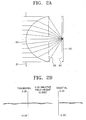
- Figures 2A and 2B are views respectively showing the optical path and the aberration of the first light beam when the first light beam is focused by an objective lens formed according to the design data of Table 1 to form a light spot on a recording surface of the first optical disc, in the compatible optical pickup according to the present invention of Figure 1;
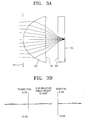
- Figure 3A and 3B are views respectively showing the optical path and the aberration of the second light beam when the second light beam is focused by an objective lens formed according to the design data of Table 1 to form a light spot on a recording surface of the second optical disc, in the compatible optical pickup according to the present invention of Figure 1;
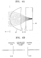
- Figure 4A and 4B are views respectively showing the optical path and the aberration of the third light beam when the third light beam is focused by an objective lens formed according to the design data of Table 1 to form a light spot on a recording surface of the third optical disc, in the compatible optical pickup according to the present invention of Figure 1;
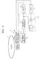
- Figure 5 is a view schematically showing a preferred embodiment of an optical disc system adopting the compatible optical pickup according to the present invention
- Figure 6 is a view schematically showing another preferred embodiment of an NA adjusting member adopted in the compatible optical pickup according to the present invention.
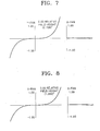
- Figure 7 is a view showing aberration generated when a second light beam having a 650 nm wavelength ⁇ 2 is focused by an objective lens to form a light spot on the recording surface of a DVD when the objective lens is shifted by 0.4 mm during the reproduction of the DVD by using the compatible optical pickup according to the present invention
- Figure 8 is a view showing aberration generated when a third light beam having a 780 nm wavelength ⁇ 3 is focused by an objective lens to form a light spot on the recording surface of a CD when the objective lens is shifted by 0.4 mm during the reproduction of the CD by using the compatible optical pickup according to the present invention
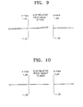
- Figure 9 is a view showing aberration generated when radial tilt is applied to an objective lens corresponding to the amount of shift of the objective lens during the shifting of the objective lens under the same conditions shown in Figure 7;
- Figure 10 is a view showing aberration generated when radial tilt is applied to an objective lens corresponding to the amount of shift of the objective lens during the shifting of the objective lens under the same conditions shown in Figure 8;
- Figure 11 is a view schematically showing a first preferred embodiment of a photodetector and a tracking error signal detection circuit which can be applied to the compatible optical pickup according to the present invention.
- Figure 12 is a view schematically showing a second preferred embodiment of the photodetector and the tracking error signal detection circuit which can be applied to the compatible optical pickup according to the present invention.
- a compatible optical pickup includes a plurality of light sources for emitting light beams having wavelength suitable for the respective optical discs having different formats, a single objective lens, and an actuator capable of making the objective lens tilt in a radial direction of the optical disc.
- the compatible optical pickup according to the present invention has an optical arrangement such that a divergent beam can be incident on the objective lens with respect to an optical disc having a thickness deviated from optimal design conditions of the objective lens, and is operated to apply radial tilt to the objective lens to correspond to the shift of the objective lens when the objective lens is shifted in the radial direction of the objective lens.
- the compatible optical pickup since a divergent beam is used to an optical disc whose thickness is out of a range of the optimal design conditions of the objective lens, not only spherical aberration due to the difference in thickness between the optical discs can be corrected, but also a sufficient working distance so that the optical disc and the objective lens do not collide with each other can be secured. Also, when the objective lens is shifted in the radial direction, generation of aberration, in particular, coma aberration, is restricted so that superior tracking and reproduction signals can be detected.
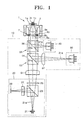
- Figure 1 schematically shows the optical configuration of an optical pickup according to a preferred embodiment of the present invention.
- a compatible optical pickup includes an optical unit 10 for emitting light beams having wavelengths suitable for the respective optical discs 1a, 1b, and 1c toward an optical discs 1 and receiving the light beams traveling back after being reflected by the optical disc 1 to detect an information reproduction signal and/or an error signal, an objective lens 3 for focusing an incident light beam to form a light spot on a recording surface of the optical disc 1, and an actuator 5 for making the objective lens 3 tilt in a radial direction of the optical disc 1.
- the optical unit 10 includes first through third optical units 20, 30, and 40 for emitting first through third light beams 21a, 31a, and 41a having wavelengths suitable for the first through third optical discs 1a, 1b, and 1c having different thicknesses and receiving the first through third light beams 21a, 31a, and 41a traveling back after being reflected by the optical disc 1 to detect an information reproduction signal and/or an error signal, a first optical path changer 53 arranged between the first and second optical units 20 and 30 and the objective lens 3, a second optical path changer 55 arranged between the first optical path changer 53 and the objective lens 3, a first collimating lens 51 arranged between the first optical unit 20 and the first optical path changer 53, and a second collimating lens 57 arranged between the second optical unit 30 and the first optical path changer 53.
- the first optical unit 20, as shown in Figure 1, includes a blue-violet light source 21 for emitting the first light beam 21a having a blue-violet wavelength, for example, a 405 nm wavelength, suitable for the first optical disc 1a, for example, a next generation DVD family optical disc (hereinafter, referred to as the next generation DVD) that has a high density than that of a DVD, a polarizing beam splitter 23 for transmitting or reflecting the incident first light beam 21a according to the polarization thereof, a quarter wave plate to the wavelength of the first light beam 21a for changing the polarization of the first light beam 21a, a photodetector 29 for detecting an information reproduction signal and/or an error signal by receiving the first light beam 21a traveling back after being reflected by the optical disc 1, and a sensing lens 27 arranged between the polarizing beam splitter 23 and the photodetector 29.
- a blue-violet light source 21 for emitting the first light beam 21a having a blue-violet wavelength
- An astigmatism lens may be provided as the sensing lens 27 so that a focus error signal can be detected in an astigmatic method by generating astigmatism in the first light beam 21a.
- a hologram optical module for a near infrared wavelength, for example, a 780 nm wavelength, suitable for the third optical disc 1c, for example, a CD family optical disc (hereinafter, referred to as the CD) may be provided as the third optical unit 40.
- the hologram optical module includes a light source for emitting a light beam having a predetermined wavelength, for example, a 650 nm or 780 nm wavelength, a photodetector arranged at the side of the light source and receiving the light beam traveling back after being reflected by the optical disc 1 to detect an information reproduction and/or error signal, and a hologram element for transmitting most of the incident light beam output from the light source straight and diffracting the light beam traveling back after being reflected by the optical disc 1 into the +1 st order or -1 st order light beam to proceed toward the photodetector.
- a light source for emitting a light beam having a predetermined wavelength, for example, a 650 nm or 780 nm wavelength
- a photodetector arranged at the side of the light source and receiving the light beam traveling back after being reflected by the optical disc 1 to detect an information reproduction and/or error signal
- a hologram element for transmitting most of the incident light beam output from the
- the hologram optical module may further include a grating to detect a tracking error signal, for example, in a DPP (differential push-pull) method.
- a DPP differential push-pull
- the photodetector of the hologram optical module has a structure so that it can detect a tracking error signal in the DPP method.
- detailed descriptions and illustrations of the hologram optical module for a red wavelength for a DVD and the hologram optical module for a near infrared wavelength for a CD respectively adopted as the second and third optical units 30 and 40 will be omitted.
- the second and third optical units 30 and 40 may have the optical structure in which the light source and the photodetector are separately provided as in the first optical unit 20, instead of having a structure of the hologram optical module. Also, a hologram optical module for a blue-violet wavelength, for example, a 405 nm wavelength, for the next generation DVD may be provided as the first optical unit 20.
- the objective lens 3 is optimized to an optical disc having the highest density, for example, the first optical disc 1a, among the first through third optical discs 1a, 1b, and 1c.
- the second and third optical units 30 and 40 preferably includes a photodetector having at least a four-section structure in a direction (a direction R) corresponding to the radial direction of the optical disc, as shown in Figures 11 and 12 which will be described later, to detect a racking error signal in which a tracking error offset is minimized.
- the photodetector of the first optical unit 20 preferably has at least a four-section structure in the direction R, as shown in Figures 11 and 12.
- the first optical path changer 53 is arranged between the first and second optical units 20 and 30 and the objective lens 3, and makes the first and second light beams 21a and 31a output from the first and second optical units 20 and 30 proceed toward the objective lens 3 and the first and second light beams 21a and 31a traveling back after being reflected by the optical disc 1 proceed toward the first and second optical units 20 and 30.
- a beam splitter 54 having a mirror surface 54a at which the first light beam 21a is transmitted while the second light beam 31a is totally reflected may be provided as the first optical path changer 53.
- the second optical path changer 55 is arranged between the first optical path changer 53 and the objective lens 3, and transmits the first and second light beams 21a and 31a output from the first and second optical units 20 and 30 and reflects the third light beam 41a output form the third optical unit 40.
- a beam splitter 56 having a mirror surface 56a at which all or part of the first and second light beams 21a 31a are transmitted while all or part of the third light beam 41a is reflected may be provided as the second optical path changer 55.
- the first collimating lens 51 is arranged between the first optical unit 20 and the first optical path changer 53, and changes the first light beam 21a output from the first optical unit 20 in the form of a divergent beam into a parallel beam to be incident on the objective lens 3.
- the objective lens 3 is designed to be optimized to the first light beam 21a that is a parallel beam.
- the first light beam 21a is incident on the objective lens 3 in the form of a parallel beam, and the objective lens 3 is designed to be optimized to the first light beam 21a and the first optical disc 1a, superior reproduction and tracking error signals can be detected during the shifting of the objective lens 3 in the radial direction.
- the second collimating lens 57 is arranged between the second optical unit 30 and the first optical path changer 53.
- the second collimating lens 57 is preferably provided to change the second light beam 31a output from the second optical unit 30 in the form of a divergent beam to a divergent beam close to a parallel beam.
- the position of the light source of the second optical unit 30 is disposed at a position deviated from the focal point of the second collimating lens 57, that is, at the position shorter than a focal length, the second light beam 31a still diverges after passing through the second collimating lens 57 so that the second light beam 31a can be changed to a divergent beam close to a parallel beam.
- the second light beam 31a is incident on the objective lens 3 in the form of a divergent beam close to a parallel beam
- the second optical disc 1b when the second optical disc 1b is adopted, generation of spherical aberration due to the difference in thickness between the first optical disc 1a and the second optical disc 1b and the difference in wavelength between the second light beam 31a and the first light beam 21a can be restricted.
- the third optical disc 1c since the third light beam 41a output from the third optical unit 40 is incident on the objective lens 3 in the form of a divergent beam, the light source of the third optical unit 40 and the objective lens 3 constitute a finite optical system.
- the third optical disc 1c when the third optical disc 1c is adopted, not only generation of spherical aberration due to the difference in thickness between the first optical disc 1a and the third optical disc 1c and the difference in wavelength between the third light beam 41a and the first light beam 21a can be restricted, but also a sufficient working distance can be secured so that the third optical disc 1c and the objective lens 3 do not collide with each other.
- Figure 1 shows that the second collimating lens 37 is included, it is possible to correct the spherical aberration even when the objective lens 3 and the second optical unit 30 only constitute a finite optical system without the second collimating lens 57.
- a collimating lens (not shown) for changing the third light beam 41a to a divergent beam close to a parallel beam may be further provided between the third optical unit 40 and the second optical path changer 55.
- Figure 1 shows a preferred embodiment of the optical configuration of the optical unit 10 of the compatible optical pickup according to the present invention
- the optical unit 10 of the compatible optical pickup according to the present invention is not limited to the optical configuration of Figure 1. That is, the optical configuration of the optical unit 10 according to the present invention can be modified in a variety of ways within a range of the technical concept of the present invention.
- the objective lens 3 is preferably optimized to the first optical disc 1a that is the highest density optical disc. Also, to compatibly adopt the second and third optical discs 1b and 1c, the objective lens 3 is preferably provided between the second and third optical discs 1b and 1c and the objective lens 3 with a sufficient working distance so that the second and third optical discs 1b and 1c and the objective lens 3 do not collide with each other when the second and third light beams 31a and 41a input in the form of divergent beams are focused to form light spots on the recording surfaces of the second and third optical discs 1b and 1c, respectively.
- the objective lens 3 is preferably has an NA of 0.85 or more to a thickness of 0,1 mm and a 405 nm wavelength.
- the objective lens 3 is designed to the first light beam 21a in the form of a parallel beam.
- the objective lens 3 is optimized to the first optical disc 1a and provided to have a sufficient working distance when the second and third optical discs 1b and 1c are adopted, if the second and third light beams 31a and 41a are incident on the objective lens 3 in the form of a parallel beam, spherical aberration due to the difference in thickness with the first optical disc 1a may be generated in the second and third light beams 31a and 41a formed as light spots on the recording surfaces of the second and third light beams 31a and 41a by being focused by the objective lens 3.
- the second and third light beams 31a and 41a output from the second and third optical units 30 and 40 are incident on the objective lens 3 in the form of divergent beams, the generation of spherical aberration due to the difference in thickness between the second and third optical discs 1b and 1c and the first optical disc 1a can be sufficiently restricted.
- Table 1 shows a detailed design example of the objective lens 3 that can compatibly adopt the first through third optical discs 1a, 1b, and 1c having different thicknesses and can be adopted in the compatible optical pickup according to the present invention.
- Table 1 shows data of the objective lens 3 designed to the first light beam 21a input in the form of a parallel beam and the second and third light beams 31a and 41a input in the form of divergent beams, when the wavelengths of the first through third light beams 21a, 31a, and 41a are 405 nm, 650 nm, and 780 nm, respectively, the thicknesses of the first through third optical discs 1a, 1b, and 1c are 0.1 mm, 0.6 mm, and 1.2 mm, respectively, and the effective NA to the first through third light beams 21a, 31a, and 41a are 0.85, 0.60, and 0.45, respectively.
- BaCD5_HOYA is an optical medium forming the objective lens 3 and has refractive indices of 1.605256, 1.586422, and 1.582509 with respect to the wavelengths of 405 nm, 650 nm, and 780 nm, respectively.
- 'CG' is an optical medium from light incident surfaces of the first through third optical discs 1a, 1b, and 1c to the recording surface and has refractive indices of 1.621462, 1.581922, and 1.575091 with respect to the wavelengths of 405 nm, 650 nm, and 780 nm, respectively.
- K denotes a conic constant of the aspheric surfaces 1 and 2 S2 and S3 that are lens surfaces of the objective lens 3.
- A, B, C, D, E, F, G, H, and J are aspheric coefficients.
- S1-S5 indicating surfaces in Table 1 are shown in Figures 2A through 4a for reference.
- h denotes a height from an optical axis
- c denotes a curvature
- K denotes a conic coefficient
- A-J denote aspheric coefficients.
- the objective lens 3 having the design data of Table 1 has sufficient working distances of 1.15590 mm, 1.09329 mm, and 0.84607 mm with respect to the first through third optical discs 1a, 1b, and 1c having thicknesses of 0.1 mm, 0.6 mm, and 1.2 m, respectively, so that the objective lens 3 does not collide with the optical disc 1 when the second and third optical discs 1b and 1c having thicknesses deviated from the optimal design conditions of the objective lens 3, that is, a DVD and a CD, are adopted.
- the objective lens 3 having the design data of Table 1 is designed to an incident light beam in the form of a divergent beam with respect to a light beam having a wavelength deviated from the optimal design conditions.
- the objective lens 3 since the second and third light beams 31a and 41a are incident on the objective lens 3 in the form of a divergent beam in the compatible optical pickup according to a preferred embodiment of the present invention, the objective lens 3 has a sufficiently low optical path difference (OPD) with respect to the second and third optical discs 1b and 1c.
- OPD optical path difference
- Figures 2A and 2B show the optical path and aberration of the first light beam 21a when a light spot is formed on the recording surface of the first optical disc 1a by focusing the first light beam 21a by using the objective lens 3 formed according to the design data of Table 1, respectively.
- Figures 3A and 3B show the optical path and aberration of the second light beam 31a when a light spot is formed on the recording surface of the second optical disc 1b by focusing the second light beam 31a by using the objective lens 3 formed according to the design data of Table 1, respectively.
- Figures 4A and 4B show the optical path and aberration of the third light beam 41a when a light spot is formed on the recording surface of the third optical disc 1c by focusing the third light beam 41a by using the objective lens 3 formed according to the design data of Table 1, respectively.
- Figures 2B, 3B, and 4B show the OPDs with respect to the first light beam 21a having a 405 nm wavelength, the second light beam 31a having a 650 nm wavelength, and the third light beam 41a having a 780 nm wavelength, respectively.
- the objective lens 3 formed according to the design data of Table 1 has a sufficiently low OPD when it focuses the first through third light beams 21a, 31a, and 41a and forms a light spot on the recording surface of the first through third optical discs 1a, 1b, and 1c.
- the compatible optical pickup according to a preferred embodiment of the present invention adopting the objective lens 3 formed according to the design data of Table 1 can compatibly adopt the first through third optical discs 1a, 1b, and 1c.
- the objective lens 3 is mounted on the actuator 5.
- the actuator 5 is preferably capable of tilting the objective lens 3 in a radial direction of the optical disc 1.
- An actuator that can not only move the objective lens 3 in a focus direction and a tracking direction but also adjust the objective lens 3 in a radial tilt direction is provide as the actuator 5. Since the actuator 5 capable of adjusting the objective lens 3 in the focus direction, tracking direction, and radial tilt direction is a well-known technology in the field to which the present invention pertains, detailed descriptions of the structure and operation of the actuator 5 will be omitted.
- the amount of inclination of the actuator 5, that is, the amount of inclination of the objective lens 3 is proportional to the translational motion of the objective lens 3 in the radial direction of the optical disc 1. Also, the amount of inclination of the objective lens 3 can be detected from the current applied to a coil of a tracking actuator portion of the actuator 5 to make the objective lens 3 perform a translational motion in the radial direction.
- an optical disc system adopting the compatible optical pickup according to the present invention may have the structure as shown in Figure 5 and can control the movement of the objective lens 3 as follows.
- the actuator 5 preferably includes a tilt actuator portion 5a for the control of radial tilting and a tracking actuator portion 5b for the control of tracking.
- the actuator 5 preferably includes a focus actuator portion (not shown) for the control of focusing.
- actuators having a variety of structures capable of applying radial tilt to the objective lens 3 that are well known in the present technical field can be used as the actuator 5 in the compatible optical pickup according to the present invention.
- a tracking error signal TES is detected by using a compatible optical pickup optical system 100 according to the present invention.
- a tracking driving signal TRD is obtained by calculating the TES and the tracking actuator portion 5b and the tilt actuator portion 5a are driven by using the tracking driving signal.
- reference numeral 110 denotes a servo circuit
- reference numeral 111 denotes a low pass filter
- reference numeral 113 denotes a gain adjuster.
- Reference numeral 105 denotes an RF signal amplifier for amplifying a signal output from the photodetectors of the optical units 20, 30, and 40 of the compatible optical pickup optical system 100 according to the present invention.
- Reference numeral 115 denotes a tracking controller and reference numerals 117 and 119 are drivers for driving the tracking actuator portion 5b and the tilt actuator portion 5a, respectively.
- reference numeral 115 denotes a tracking controller and reference numerals 117 and 119 are drivers for driving the tracking actuator portion 5b and the tilt actuator portion 5a, respectively.
- the amount of inclination of the objective lens 3 is proportional to a translational motion of the objective lens 3 in the radial direction of the optical disc 1.
- the amount of tilting of the objective lens 3 can be detected from the current applied to a coil of the tracking actuator portion 5b to make the objective lens 3 perform a translational motion in the radial direction of the optical disc 1.
- the compatible optical pickup according to the present invention further includes an NA adjusting member 7 for adjusting an effective NA with respect to the light beam having a wavelength deviated from the optimal design conditions of the objective lens 3 for a relatively low density optical disc.
- the NA adjusting member 7 includes a central transmission area transmitting an incident light beam for a high density optical disc and a low density optical disc and having a diameter corresponding to an effect NA suitable for at least one low density optical disc and an NA adjustment area, disposed outside the central transmission area to block a light beam for a low density optical disc that is an NA limit object.
- the NA adjusting member 7 has a structure to adjust NA of the second and third light beams 31a and 41a so that the second and third light beams 31a and 41a focused by the objective lens 3 have effective NAs suitable for the second and third optical discs 1 and 1c.
- the NA adjusting member 7 includes a first central transmission area 8a having a diameter corresponding to an effective NA suitable for the second optical disc 1b to make the effective NA of the second light beam 31a to be 0.6 and a second central transmission area 9a having a diameter corresponding to an effective NA suitable for the third optical disc 1c to make the effective NA of the third light beam 41a to be 0.45.
- a first NA adjustment area 8b around the first central transmission area 8a is formed of a hologram or a wavelength selective filter to block the second light beam 31a for the second optical disc 1b, that is an NA limit object, and transmit the first light beam 21a.
- a second NA adjustment area 9b around the second central transmission area 9a is formed of a hologram or a wavelength selective filter to block the third light beam 41a for the third optical disc 1c, that is an NA limit object, and transmit the first and second light beams 21a ad 31a.
- the NA adjusting member 7 is preferably mounted on the actuator 5 together with the objective lens 3.
- the NA adjusting member 7 is provided as a separate member from the objective lens 3, it can be integrally formed with the objective lens 3.
- the first central transmission area 8a and the first NA adjustment area 8b of the NA adjusting member 7 can be formed on one lens surface facing the optical unit 10 of the objective lens 3, whereas the second central transmission area 9a and the second NA adjustment area 9b of the NA adjusting member 7 can be formed on the other lens surface of the objective lens 3.
- the compatible optical pickup according to the present invention may include an NA adjusting member 17 as shown in Figure 6 instead of the NA adjusting member 7.
- the NA adjusting member 17 includes a first central transmission area 17a for transmitting all the wavelengths of the first through third light beams 21a, 31a, and 41a, a first NA adjustment area 17b for transmitting only the wavelengths of the first and second light beams 21a and 31a (light beams in blue-violet and red wavelength), and a second NA adjustment area 17c for transmitting only the wavelength of the first light beam 21a (a light beam in a blue-violet wavelength).
- the diameter of the first central transmission area 17a (the inner diameter of the first NA adjustment area 17b) preferably has a size corresponding to an effective NA, for example, 0.45, suitable for the third optical disc 1c while the diameter of the first NA adjustment area 17b (the inner diameter of the second NA adjustment area 17c) preferably has a size corresponding to an effective NA, for example, 0.6, suitable for the second optical disc 1b.
- the NA adjusting member 17 can be formed by coating one lens surface of the objective lens 3 or an additional transparent plate.
- the coating is performed such that no phase difference is generated between the first central transmission area and the first and second NA adjustment areas 17a, 17b, and 17c. That is, the coating is performed such that the phase change would be identical when the first light beam 21a passes through each of the first central transmission area and the first and second NA adjustment areas 17a, 17b, and 17c.
- the compatible optical pickup having the above structure, as follows, when the first optical disc 1a having a thickness corresponding to the optimal design conditions of the objective lens 3 is adopted, superior reproduction and tracking error signals can be detected and when the second and third optical discs 1b and 1c having thicknesses deviated from the optimal design conditions of the objective lens 3 are adopted, a sufficient working distance can be secured and, since the generation of spherical aberration and coma aberration are restricted, superior reproduction and tracking error signals can be detected.
- the light source 21 of the first optical unit 20 is operated to emit the first light beam 21a.
- the objective lens 3 is designed to be optimal to the wavelength the first light beam 21a and the thickness of the first optical disc 1a, spherical aberration is hardly generated when a light spot is formed on the recording surface of the first optical disc 1a by focusing the first light beam 21a emitted from the first optical unit 20 by the objective lens 3. Also, coma aberration is hardly generated when the objective lens 3 is shifted in the radial direction of the first optical disc 1a. Thus, very superior tracking and reproduction signals can be detected.
- the light sources of the second and third optical units 30 and 40 are operated to emit the second and third light beams 31a and 41a. Since the second and third light beams 31a and 41a are incident on the objective lens 3 as a divergent beam, spherical aberration due to the difference in thickness between the second and third optical discs 1b and 1c and the first optical disc 1a and the difference in wavelength between the second and third light beams 31a and 41a and the first light beam 21a can be sufficiently corrected. Also, as can be seen from the design example of the objective lens of Table 1, a sufficient working distance can be obtained.
- the compatible optical pickup according to a preferred embodiment of the present invention, when the second and third optical discs 1b and 1c deviated from the optimal design conditions of the objective lens 3 are adopted, the generation of coma aberration due to the shift of the objective lens 3 in the radial direction can be sufficiently restricted. Thus, when the second and this optical discs 1b and 1c are adopted, superior reproduction and tracking error signals can be detected.
- FIGS 7 and 8 show the aberration when a light spot is formed on the recording surface of a DVD and a CD by focusing the second light beam 31a having a 650 nm wavelength ⁇ 2 and a third light beam 41a having a 780 nm wavelength ⁇ 3 by the objective lens 3 when the objective lens 3 is shifted by 0.4 mm during the reproduction of the DVD and CD.
- optical aberration in particular, coma aberration
- Table 2 optical aberration (OPDrms) is generated as much as 0.201 ⁇ 2 with respect to a DVD and optical aberration (OPDrms) is generated as much as 0.167 ⁇ 3 with respect to a CD.
- Objective lens shift/Objective lens radial tilt OPDrms DVD 0.0 mm/0° 0.005 ⁇ 2 0.4nnm/0° 0.201 ⁇ 2 0.4 mm/1.2° 0.011 ⁇ 2 CD 0.0 mm/0° 0.001 ⁇ 3 0.4 mm/0° 0.167 ⁇ 3 0.4 mm/2.0° 0.012 ⁇ 3
- the compatible optical pickup according to the present invention when the optical disc having a thickness deviated from the optimal design conditions of the objective lens 3 is adopted, the generation of coma aberration can be restricted during the shift of the objective lens 3 so that superior tracking error and reproduction signals can be detected.
- a push-pull method can be used for the detection of a tracking error signal with respect to a recordable optical disc
- a tracking error signal offset is generated by the shift of the objective lens 3 in the radial direction
- DPP differential push pull
- a tracking error signal detection technology as shown in Figures 11 and 12 is further preferably adopted.
- a photodetector 200 for detecting an information signal and/or error signal by receiving the light beam reflected by the recording surface of the optical disc 1 preferably has a structure having at least four sections divided in a direction corresponding to the radial direction of the optical disc 1.
- the photodetector 200 may be photodetectors of the second and third optical units 30 and 40.
- the photodetector 200 may be the photodetector 29 of the first optical unit 20.
- the photodetector 200 preferably has a structure sectioned such that a base ball pattern portion of a light beam reflected and/or diffracted by the optical disc 1 due to a periodic structure in a track direction of the optical disc 1 is received only by outer section regions S3 and S4 of the photodetector 200.
- the base ball pattern portion means a portion where the 0 th order diffractive light and the +1 st order diffractive light of the light reflected/diffracted by the optical disk 1 are overlapped and a portion where the 0 th order diffractive light and the -1 st order diffractive light of the light reflected/diffracted by the optical disk 1 are overlapped.
- a tracking error signal detection circuit 250 includes a first subtracter 251 for obtaining a subtracting signal between detection signals of inner section regions S1 and S4 of four section regions of the photodetector 200, a second subtracter 255 for obtaining a subtracting signal between detection signals of the outer section regions S3 and S4, a gain adjuster 253 for applying a predetermined gain ⁇ to a signal output from the first subtracter 251, and a third subtracter 257 for obtaining a subtracting signal between a signal output from the gain adjuster 253 and a signal output from the second subtracter 255.
- a tracking error signal TES can be detected as in Mathematic Formula 4.
- ⁇ is a gain
- a predetermined gain ⁇ is applied to a subtracting signal between the detection signals of the inner section regions S1 and S2.
- a gain is applied to a subtracting signal between the detection signals of the outer section regions S3 and S4, instead of applying a gain to a difference signal between the detection signals of the inner section regions S1 and S2, or an appropriate gain to each of the subtracting signal between the inner section regions S1 and S2 and the subtracting signal between the detection signals of the outer section regions S3 and S4.
- the photodetector 200 is described and illustrated to be divided into four sections in a direction corresponding to the radial direction of the optical disc 1 in Figure 11, the photodetector 200, for example, as shown in Figure 12, may have an eight-section structure by being divided into four sections in a direction corresponding to the radial direction of the optical disc 1 and into two sections in a direction corresponding to the tangential direction of the optical-disc 1, or the photodetector 200 may have a sixteen-section structure.
- a tracking error signal detection circuit 250' is modified considering the section structure of a photodetector 200', but is actually the same as the tracking error signal detection circuit 250 shown in Figure 11.
- a tracking error signal detection technology in the DPP method or the tracking error signal detection technology as shown in Figures 11 and 12 can be applied to the first optical disc 1a having the format satisfying the optimal design conditions of the objective lens 3.
- the compatible optical pickup according to the present invention is described and illustrated to include the three optical unit 10 for emitting light beams having different wavelengths to compatible adopt the next generation DVD, DVD, and CD.
- the present invention is not limited thereto and a variety of preferred embodiments of the compatible optical pickup are available.
- a high density optical disc and a low density optical disc having different thicknesses can be compatibly adopted. Also, a superior aberration characteristic can be obtained without additional optical parts with respect to the low density optical disc when the objective lens is shifted in the radial direction of the optical disc.
Landscapes
- Physics & Mathematics (AREA)
- Optics & Photonics (AREA)
- Optical Head (AREA)
- Optical Recording Or Reproduction (AREA)
Applications Claiming Priority (2)
| Application Number | Priority Date | Filing Date | Title |
|---|---|---|---|
| KR1020020031491A KR20030093683A (ko) | 2002-06-05 | 2002-06-05 | 호환형 광픽업 |
| KR2002031491 | 2002-06-05 |
Publications (2)
| Publication Number | Publication Date |
|---|---|
| EP1369853A2 true EP1369853A2 (de) | 2003-12-10 |
| EP1369853A3 EP1369853A3 (de) | 2004-01-21 |
Family
ID=36121962
Family Applications (1)
| Application Number | Title | Priority Date | Filing Date |
|---|---|---|---|
| EP03253435A Withdrawn EP1369853A3 (de) | 2002-06-05 | 2003-05-31 | Kompatibles optisches Abtastgerät |
Country Status (6)
| Country | Link |
|---|---|
| US (1) | US7372794B2 (de) |
| EP (1) | EP1369853A3 (de) |
| JP (1) | JP2004014095A (de) |
| KR (1) | KR20030093683A (de) |
| CN (1) | CN1469358A (de) |
| TW (1) | TWI231492B (de) |
Families Citing this family (22)
| Publication number | Priority date | Publication date | Assignee | Title |
|---|---|---|---|---|
| JP2005071462A (ja) * | 2003-08-22 | 2005-03-17 | Victor Co Of Japan Ltd | 光ピックアップ装置 |
| JP2005108321A (ja) * | 2003-09-30 | 2005-04-21 | Konica Minolta Opto Inc | 光ピックアップ装置及び光情報記録再生装置 |
| JP2005129186A (ja) * | 2003-10-27 | 2005-05-19 | Konica Minolta Opto Inc | 光ピックアップ装置 |
| JP2005293765A (ja) * | 2004-04-02 | 2005-10-20 | Konica Minolta Opto Inc | 光ピックアップ装置 |
| TW200604563A (en) * | 2004-07-22 | 2006-02-01 | Hitachi Maxell | Light shield sheet, optical apparatus, and method of manufacturing light shield sheet |
| JP4522829B2 (ja) * | 2004-11-22 | 2010-08-11 | 株式会社リコー | 光ピックアップ及び補正用収差発生方法とこれを用いた光情報処理装置 |
| KR100669984B1 (ko) * | 2005-01-24 | 2007-01-19 | 삼성전자주식회사 | 광픽업장치 |
| JP2006323907A (ja) * | 2005-05-18 | 2006-11-30 | Hitachi Media Electoronics Co Ltd | 光ピックアップ装置 |
| JPWO2006126466A1 (ja) * | 2005-05-26 | 2008-12-25 | コニカミノルタオプト株式会社 | 光ピックアップ装置及び対物レンズ |
| JP4542031B2 (ja) * | 2005-12-28 | 2010-09-08 | 三星電子株式会社 | 互換系光情報記録再生装置 |
| JP2007280541A (ja) * | 2006-04-07 | 2007-10-25 | Funai Electric Co Ltd | 収差補正装置およびディスク装置 |
| JP4849939B2 (ja) * | 2006-04-10 | 2012-01-11 | Hoya株式会社 | 光情報記録再生装置 |
| JP2007280549A (ja) * | 2006-04-10 | 2007-10-25 | Sony Corp | 光ピックアップ及び光ディスク装置 |
| US7848020B2 (en) * | 2006-06-02 | 2010-12-07 | Jds Uniphase Corporation | Thin-film design for positive and/or negative C-plate |
| EP1892543A1 (de) | 2006-08-23 | 2008-02-27 | JDS Uniphase Corporation | Kartesische Polarisatoren mit lichtausgerichteten Flüssigkristallen |
| JP2008097661A (ja) * | 2006-10-06 | 2008-04-24 | Sanyo Electric Co Ltd | 光ピックアップ装置 |
| JP4850032B2 (ja) | 2006-11-08 | 2012-01-11 | 日立マクセル株式会社 | 光ピックアップレンズ |
| JP2009181689A (ja) * | 2008-01-30 | 2009-08-13 | Jds Uniphase Corp | 2ミラー位相シフタを有する光ピックアップ・ユニット |
| JP4477096B2 (ja) * | 2009-12-14 | 2010-06-09 | 日立マクセル株式会社 | 光ピックアップレンズ |
| JP4932959B2 (ja) * | 2011-09-09 | 2012-05-16 | 日立マクセル株式会社 | 光ディスク装置 |
| JP5827983B2 (ja) * | 2013-10-11 | 2015-12-02 | 日立マクセル株式会社 | 光ディスク装置 |
| JP6820547B2 (ja) * | 2016-03-09 | 2021-01-27 | パナソニックIpマネジメント株式会社 | 記録再生装置 |
Family Cites Families (129)
| Publication number | Priority date | Publication date | Assignee | Title |
|---|---|---|---|---|
| GB508448A (en) | 1937-09-24 | 1939-06-30 | Jeno Dulovits | Improvements in soft effect attachments for use with photographic objectives |
| US2233591A (en) | 1937-09-24 | 1941-03-04 | Dulovits Jeno | Soft effect screen lens |
| US3305294A (en) | 1964-12-03 | 1967-02-21 | Optical Res & Dev Corp | Two-element variable-power spherical lens |
| DE2445333A1 (de) | 1973-10-01 | 1975-04-10 | Philips Nv | Optoelektronisches system zur bestimmung einer abweichung zwischen der istlage und der sollage einer ebene in einem optischen abbildungssystem |
| US3958884A (en) | 1974-04-24 | 1976-05-25 | Vickers Limited | Interferometric apparatus |
| US4210391A (en) | 1977-09-14 | 1980-07-01 | Cohen Allen L | Multifocal zone plate |
| JPS5724336Y2 (de) | 1977-10-08 | 1982-05-26 | ||
| US4340283A (en) | 1978-12-18 | 1982-07-20 | Cohen Allen L | Phase shift multifocal zone plate |
| US4545653A (en) | 1981-01-07 | 1985-10-08 | Digital Recording Corporation | Focusing elements and system for producing a prescribed energy distribution along an axial focal zone |
| JPS5942517A (ja) | 1982-09-02 | 1984-03-09 | Nippon Kogaku Kk <Nikon> | 二重焦点光学系 |
| US4501493A (en) | 1982-10-28 | 1985-02-26 | Sony Corporation | Apparatus for detecting a position of an optical pickup |
| NL8303932A (nl) | 1982-11-17 | 1984-06-18 | Pioneer Electronic Corp | Opneeminrichting voor optische plaat. |
| JPS59147306A (ja) | 1983-02-10 | 1984-08-23 | Sony Corp | フオ−カス誤差検出装置 |
| SE459128B (sv) | 1983-03-29 | 1989-06-05 | Svensk Filmindustri | Avbildningsobjektiv som foermaar att i ett bildplan skarpt avbilda foeremaal paa minst tvaa olika avstaand fraan objektivet |
| JPS59221835A (ja) | 1983-05-31 | 1984-12-13 | Sony Corp | フオ−カス誤差検出装置 |
| JPS6273429A (ja) | 1985-09-26 | 1987-04-04 | Toshiba Corp | 光学式ピツクアツプの位置検出装置 |
| JPH0765407B2 (ja) | 1987-03-04 | 1995-07-19 | カヤバ工業株式会社 | 制振装置の制御方法 |
| US4981342A (en) | 1987-09-24 | 1991-01-01 | Allergan Inc. | Multifocal birefringent lens system |
| EP0311340B1 (de) | 1987-10-05 | 1993-08-04 | Matsushita Electric Industrial Co., Ltd. | Optische Lesekopf |
| US5156943A (en) | 1987-10-25 | 1992-10-20 | Whitney Theodore R | High resolution imagery systems and methods |
| JPH01151022A (ja) | 1987-12-09 | 1989-06-13 | Sharp Corp | 光ピックアップ装置 |
| NL8800133A (nl) | 1988-01-21 | 1989-08-16 | Philips Nv | Inrichting voor het met optische straling aftasten van een informatievlak. |
| EP0334601B1 (de) | 1988-03-25 | 1994-09-07 | Tosoh Corporation | Fehlerdetektorvorrichtung für einen optischen Abtastkopf |
| JPH0798431B2 (ja) | 1988-06-01 | 1995-10-25 | 富士写真フイルム株式会社 | 平版印刷版用支持体 |
| JP2641514B2 (ja) | 1988-07-05 | 1997-08-13 | オリンパス光学工業株式会社 | 単群対物レンズ |
| EP0351471B1 (de) | 1988-07-20 | 1996-01-31 | Allen L. Dr. Cohen | Multifokale, diffraktive optische Vorrichtung |
| US5161148A (en) | 1988-08-05 | 1992-11-03 | Matsushita Electric Industrial Co., Ltd. | Optical pick-up using wavelength guide with grating coupler therein |
| US4995714A (en) | 1988-08-26 | 1991-02-26 | Cohen Allen L | Multifocal optical device with novel phase zone plate and method for making |
| NL9000135A (nl) | 1989-01-30 | 1990-08-16 | Seiko Epson Corp | Focusseermechanisme en optische kop. |
| JPH0315003A (ja) | 1989-03-16 | 1991-01-23 | Omron Corp | グレーティング・レンズおよび集光グレーティング・カプラ |
| JPH02118508A (ja) | 1989-05-01 | 1990-05-02 | Sankyo Seiki Mfg Co Ltd | 光ディスク用レンズ |
| JPH0354740A (ja) | 1989-07-24 | 1991-03-08 | Matsushita Electric Ind Co Ltd | 光学情報記録部材および光学情報記録再生装置 |
| JPH03244450A (ja) | 1990-02-23 | 1991-10-31 | Nidek Co Ltd | 二焦点人工レンズ |
| US5120120A (en) | 1990-07-27 | 1992-06-09 | Cohen Allen L | Multifocal optical device with spurious order suppression and method for manufacture of same |
| US5235581A (en) | 1990-08-09 | 1993-08-10 | Matsushita Electric Industrial Co., Ltd. | Optical recording/reproducing apparatus for optical disks with various disk substrate thicknesses |
| JPH04178931A (ja) | 1990-11-14 | 1992-06-25 | Sanyo Electric Co Ltd | 光学記録または再生機構 |
| US5153778A (en) | 1991-06-19 | 1992-10-06 | At&T Bell Laboratories | Powerless field-corrective lens |
| US5164584A (en) | 1991-06-24 | 1992-11-17 | Ncr Corporation | Optical scanner with power efficient lens |
| US5231624A (en) | 1991-08-01 | 1993-07-27 | Tandy Corporation | System and method using a reduce profile light beam for high density recording on optical media |
| US5619488A (en) | 1991-09-07 | 1997-04-08 | Fuji Xerox Co., Ltd. | Information recording device |
| JPH0581698A (ja) | 1991-09-20 | 1993-04-02 | Sanyo Electric Co Ltd | 波長切換式光ピツクアツプ |
| US5438187A (en) | 1991-11-01 | 1995-08-01 | Spectra-Physics Scanning Systems, Inc. | Multiple focus optical system for data reading applications |
| DE69219735T2 (de) | 1991-11-20 | 1997-09-11 | Sony Corp | Optische Abtasteinrichtung und Fokusservoeinrichtung dafür |
| US5345072A (en) | 1991-12-24 | 1994-09-06 | Matsushita Electric Industrial Co., Ltd. | Focus detection device for reading information from an optical recording medium |
| US5281797A (en) | 1991-12-26 | 1994-01-25 | Hitachi, Ltd. | Short wavelength optical disk head having a changeable aperture |
| JPH0695038A (ja) | 1992-03-19 | 1994-04-08 | Matsushita Electric Ind Co Ltd | 超解像走査光学装置、光学装置の超解像用光源装置及び光学装置の超解像用フィルター |
| JP3200171B2 (ja) | 1992-06-10 | 2001-08-20 | パイオニア株式会社 | 光ディスクプレーヤ |
| US5410468A (en) | 1992-06-26 | 1995-04-25 | Matsushita Electric Industrial Co., Ltd. | Optical pick-up apparatus |
| DE69332730T2 (de) | 1992-08-07 | 2003-10-23 | Matsushita Electric Industrial Co., Ltd. | Optisches Speichergerät |
| US5615200A (en) | 1992-09-10 | 1997-03-25 | Kabushiki Kaisha Toshiba | Light beam shaping device to change an anisotropic beam to an isotropic beam for reducing the size of an optical head |
| JPH0696466A (ja) | 1992-09-14 | 1994-04-08 | Fuji Xerox Co Ltd | 光ピックアップ装置 |
| US5815293A (en) | 1993-02-01 | 1998-09-29 | Matsushita Electric Industrial Co., Ltd. | Compound objective lens having two focal points |
| JP2532818B2 (ja) | 1993-02-01 | 1996-09-11 | 松下電器産業株式会社 | 対物レンズおよび光ヘッド装置 |
| US5349471A (en) | 1993-02-16 | 1994-09-20 | The University Of Rochester | Hybrid refractive/diffractive achromatic lens for optical data storage systems |
| JP3309470B2 (ja) | 1993-03-10 | 2002-07-29 | 松下電器産業株式会社 | 光情報記録再生装置 |
| US5473471A (en) | 1993-04-16 | 1995-12-05 | Matsushita Electric Industrial Co., Ltd. | Complex lens with diffraction grating |
| US5612942A (en) | 1993-11-19 | 1997-03-18 | Nec Corporation | Optical head |
| JPH07176072A (ja) | 1993-12-20 | 1995-07-14 | Hitachi Ltd | 光ヘッド装置 |
| US5930214A (en) | 1994-01-19 | 1999-07-27 | Kabushiki Kaisha Toshiba | Recording/reproducing optical head apparatus compatible with different optical media |
| JP3435249B2 (ja) | 1994-03-11 | 2003-08-11 | 株式会社東芝 | 光学ヘッド装置およびレンズ |
| KR0171076B1 (ko) | 1994-05-13 | 1999-04-15 | 배순훈 | 서로 다른 파장의 레이저 비임을 동시에 각각 발생하여 한쪽면에 복수개의 기록층을 가지는 광디스크를 기록/재생하는 광 픽업 시스템 |
| JP2655077B2 (ja) | 1994-05-17 | 1997-09-17 | 日本電気株式会社 | 光ヘッド装置 |
| JPH0836768A (ja) * | 1994-07-21 | 1996-02-06 | Sony Corp | 対物レンズ駆動装置 |
| JP3240846B2 (ja) | 1994-08-12 | 2001-12-25 | 松下電器産業株式会社 | 光ヘッド |
| US5512158A (en) * | 1995-02-28 | 1996-04-30 | Hewlett-Packard Company | Capillary electrophoresis method and apparatus for electric field uniformity and minimal dispersion of sample fractions |
| US5526338A (en) | 1995-03-10 | 1996-06-11 | Yeda Research & Development Co. Ltd. | Method and apparatus for storage and retrieval with multilayer optical disks |
| ES2149449T3 (es) | 1995-03-15 | 2000-11-01 | Koninkl Philips Electronics Nv | Dispositivo para explorar opticamente un medio de registro. |
| JP2725632B2 (ja) | 1995-05-24 | 1998-03-11 | 日本電気株式会社 | 光ヘッド装置 |
| US5754512A (en) | 1995-05-30 | 1998-05-19 | Matsushita Electric Industrial Co., Ltd. | Correction elements to lower light intensity around an optical axis of an optical head with a plurality of focal points |
| DE69627752T2 (de) | 1995-06-05 | 2003-10-16 | Nec Corp., Tokio/Tokyo | Optische Wiedergabekopfvorrichtung für verschiedene Plattentypen |
| KR100234248B1 (ko) | 1995-06-07 | 1999-12-15 | 윤종용 | 광픽업용 2위치 결상 대물렌즈 |
| KR100234249B1 (ko) | 1995-06-07 | 1999-12-15 | 윤종용 | 광픽업용 2위치 결상 대물렌즈 |
| US5717674A (en) | 1995-06-30 | 1998-02-10 | Sanyo Electrics Co., Ltd. | Three-beam generating diffraction grating, transmission type holographic optical element and optical pickup apparatus using the same |
| JP3476989B2 (ja) | 1995-08-04 | 2003-12-10 | パイオニア株式会社 | 光ピックアップ |
| US5986779A (en) | 1995-08-18 | 1999-11-16 | Matsushita Electric Industrial Co., Ltd. | Multiple focus lens, an optical head apparatus and an optical information recording-reproducing apparatus |
| KR100234257B1 (ko) | 1995-08-30 | 1999-12-15 | 윤종용 | 대물렌즈 장치 및 안정된 포커스 서보 신호를 얻는방법 및 이를 적용한 광픽업 장치 및 두께가 다른 디스크를 판별하는 방법 및 두께가 다른 디스크로부터 정보를 재생하고 기록하는 방법 |
| US5587981A (en) | 1995-09-05 | 1996-12-24 | Kamatani; Yasuo | Multi-standard optical disk reading method having distinction process |
| US5724335A (en) | 1995-10-25 | 1998-03-03 | Konica Corporation | Objective lens for recording and reproducing for use in an optical information recording medium |
| CN1119802C (zh) | 1995-11-22 | 2003-08-27 | 松下电器产业株式会社 | 光度头 |
| KR100269105B1 (ko) | 1995-12-07 | 2000-10-16 | 윤종용 | 두께가다른디스크의호환이가능한기록재생용광픽업 |
| JP3062099B2 (ja) | 1996-02-06 | 2000-07-10 | 日本電気株式会社 | 光ヘッド装置 |
| KR100238266B1 (ko) | 1996-02-14 | 2000-02-01 | 윤종용 | 광학장치 |
| JP3677342B2 (ja) | 1996-02-23 | 2005-07-27 | 松下電器産業株式会社 | 光ヘッド装置および光ディスク装置 |
| US5777803A (en) | 1996-02-23 | 1998-07-07 | Industrial Technology Research Institute | Objective lens for optical pick-up head of optical disk drive |
| WO1997033277A1 (en) | 1996-03-08 | 1997-09-12 | Philips Electronics N.V. | Objective lens and scanning device using such an objective lens |
| JPH09320136A (ja) | 1996-03-26 | 1997-12-12 | Sanyo Electric Co Ltd | 情報記録再生装置 |
| US5768242A (en) | 1996-04-05 | 1998-06-16 | The United States Of America As Representd By The Administrator Of The National Aeronautics And Space Administration | Apparatus and method for focusing a light beam in a three-dimensional recording medium by a dynamic holographic device |
| GB2312549A (en) | 1996-04-26 | 1997-10-29 | Daewoo Electronics Co Ltd | Optical pickup device |
| JP3426084B2 (ja) | 1996-05-24 | 2003-07-14 | シャープ株式会社 | 光学式記録再生装置 |
| US5933401A (en) * | 1996-06-07 | 1999-08-03 | Samsung Electronics Co., Ltd. | Optical pickup having plural optical sources and plural optical detectors |
| KR100234261B1 (ko) | 1996-06-07 | 1999-12-15 | 윤종용 | 호환형 광픽업장치 |
| JPH103671A (ja) | 1996-06-18 | 1998-01-06 | Ricoh Co Ltd | 光ピックアップ装置及び光ピックアップ装置におけるトラッキング信号生成方法 |
| JP3844153B2 (ja) | 1996-06-18 | 2006-11-08 | 松下電器産業株式会社 | 光ヘッド装置および光情報処理方法 |
| US5659533A (en) | 1996-07-23 | 1997-08-19 | Sampo Corporation | Method of using a single pick-up head to read and store data on discs of different thicknesses and structure of a pick-up head apparatus therefor |
| US5881034A (en) * | 1996-08-20 | 1999-03-09 | Sony Corporation | Apparatus for driving objective lens |
| JPH1064097A (ja) * | 1996-08-21 | 1998-03-06 | Minebea Co Ltd | 光ピックアップ装置 |
| US5884879A (en) * | 1996-08-23 | 1999-03-23 | Gruenenfelder; Marc A. | Ergonomic support pad |
| JPH10106019A (ja) | 1996-09-24 | 1998-04-24 | Nec Corp | 2波長分離型光ヘッド |
| DE69720641T2 (de) | 1996-10-23 | 2004-04-08 | Konica Corp. | Verfahren zur Aufzeichnung und Wiedergabe eines optischen Aufzeichnungsträgers, Objektivlinse sowie Herstellungsmethode der Objektivlinse |
| CN1199162C (zh) | 1996-10-31 | 2005-04-27 | 三洋电机株式会社 | 光拾波装置 |
| KR100209918B1 (ko) | 1997-03-28 | 1999-07-15 | 윤종용 | 홀로그램형링렌즈를 사용하여 cd-r과 호환하는 dvd용 광픽업 |
| US6285645B1 (en) * | 1997-05-27 | 2001-09-04 | Asahi Glass Company Ltd. | Optical device |
| KR100291557B1 (ko) | 1997-08-30 | 2001-06-01 | 윤종용 | 환형차폐면을사용한cd-r및dvd호환광픽업 |
| US6343058B1 (en) * | 1997-10-30 | 2002-01-29 | Ricoh Company, Ltd. | Optical pickup device applicable to two kinds of recording media with minimized deterioration of a beam spot |
| US6449235B1 (en) * | 1998-04-04 | 2002-09-10 | Lg Electronics, Inc. | Optical pick-up apparatus and optical recording/reproducing apparatus using the same |
| JP3443668B2 (ja) * | 1998-04-30 | 2003-09-08 | 富士通株式会社 | 収差補正方法及び収差補正装置 |
| JP2000187870A (ja) | 1998-12-21 | 2000-07-04 | Ricoh Co Ltd | 光ピックアップ装置 |
| US6545958B1 (en) * | 1998-08-31 | 2003-04-08 | Ricoh Company, Ltd. | Optical-pickup device and tilt-detecting method thereof |
| DE69933830T2 (de) * | 1998-09-14 | 2007-06-28 | Matsushita Electric Industrial Co., Ltd., Kadoma | Neigungserkennungsvorrichtung, optisches Plattengerät, und Neigungssteuerverfahren |
| WO2000030082A1 (en) * | 1998-11-17 | 2000-05-25 | Fujitsu Limited | Optical storage device |
| US6650612B1 (en) * | 1999-03-31 | 2003-11-18 | Matsushita Electric Industrial Co., Ltd. | Optical head and recording reproduction method |
| EP1178474A1 (de) * | 1999-05-11 | 2002-02-06 | Matsushita Electric Industrial Co., Ltd. | Optischer kopf |
| JP3668054B2 (ja) | 1999-06-29 | 2005-07-06 | 京セラミタ株式会社 | キノン誘導体およびこれを用いた電子写真感光体 |
| EP1119847A1 (de) * | 1999-07-28 | 2001-08-01 | Koninklijke Philips Electronics N.V. | Optische abtastvorrichtung |
| JP2001043559A (ja) | 1999-07-30 | 2001-02-16 | Matsushita Electric Ind Co Ltd | 光ヘッド及び光ディスク装置 |
| JP4578656B2 (ja) | 1999-09-16 | 2010-11-10 | 三星電子株式会社 | 光記録再生機器用エラー信号検出装置 |
| KR100636103B1 (ko) | 1999-10-21 | 2006-10-18 | 삼성전자주식회사 | 광픽업 조립체 |
| JP2001126284A (ja) * | 1999-10-29 | 2001-05-11 | Matsushita Electric Ind Co Ltd | チルト制御装置 |
| KR100644581B1 (ko) * | 1999-10-30 | 2006-11-13 | 삼성전자주식회사 | 트랙킹 에러신호 검출장치 및 재생신호 검출장치 |
| JP2001184686A (ja) * | 1999-12-28 | 2001-07-06 | Hitachi Ltd | 対物レンズ駆動装置 |
| KR20010060784A (ko) * | 1999-12-28 | 2001-07-07 | 구자홍 | 광픽업 장치와 이를 이용한 틸트 검출 및 보상방법 |
| TW468164B (en) * | 2000-03-24 | 2001-12-11 | Ind Tech Res Inst | Conduction-wire suspension type actuator structure and current route disposition method |
| JP3967525B2 (ja) * | 2000-05-12 | 2007-08-29 | オリンパス株式会社 | レンズ駆動装置 |
| JP2002298352A (ja) | 2001-04-03 | 2002-10-11 | Matsushita Electric Ind Co Ltd | 光情報処理装置 |
| JP4817035B2 (ja) * | 2001-05-09 | 2011-11-16 | コニカミノルタホールディングス株式会社 | 対物レンズ、光ピックアップ装置、及び記録・再生装置 |
| JP2003067972A (ja) * | 2001-05-29 | 2003-03-07 | Nec Corp | 光ヘッド装置および光学式情報記録再生装置 |
| KR100828246B1 (ko) * | 2001-09-20 | 2008-05-07 | 엘지전자 주식회사 | 홀로그램 소자 및 그 홀로그램 소자를 이용한 광픽업 장치 |
| JP2003296959A (ja) * | 2002-03-26 | 2003-10-17 | Samsung Electro Mech Co Ltd | 波長選択性開口制限素子と波長選択性ビームスプリッタ及びそれを備えた光ピックアップ装置 |
| WO2003091764A1 (en) * | 2002-04-18 | 2003-11-06 | Matsushita Electric Industrial Co., Ltd. | Optical element, optical head, optical information recording/reproduction device, computer, video recording device, video reproduction device, server, and car navigation system |
-
2002
- 2002-06-05 KR KR1020020031491A patent/KR20030093683A/ko not_active Abandoned
-
2003
- 2003-04-22 TW TW092109300A patent/TWI231492B/zh not_active IP Right Cessation
- 2003-04-30 JP JP2003125427A patent/JP2004014095A/ja active Pending
- 2003-05-31 EP EP03253435A patent/EP1369853A3/de not_active Withdrawn
- 2003-06-05 CN CNA031412297A patent/CN1469358A/zh active Pending
- 2003-06-05 US US10/454,838 patent/US7372794B2/en not_active Expired - Fee Related
Also Published As
| Publication number | Publication date |
|---|---|
| US20040032815A1 (en) | 2004-02-19 |
| CN1469358A (zh) | 2004-01-21 |
| TW200307932A (en) | 2003-12-16 |
| JP2004014095A (ja) | 2004-01-15 |
| US7372794B2 (en) | 2008-05-13 |
| KR20030093683A (ko) | 2003-12-11 |
| TWI231492B (en) | 2005-04-21 |
| EP1369853A3 (de) | 2004-01-21 |
Similar Documents
| Publication | Publication Date | Title |
|---|---|---|
| EP1369853A2 (de) | Kompatibles optisches Abtastgerät | |
| JP3970747B2 (ja) | 位相補正器及びこれを採用した互換型光ピックアップ | |
| EP1001414B1 (de) | Kompatibles optisches Abtastgerät | |
| EP1313095B1 (de) | Kompatibles optisches Abstastgerät | |
| USRE43106E1 (en) | Optical pickup compatible with a digital versatile disk and a recordable compact disk using a holographic ring lens | |
| US7280458B2 (en) | Optical pickup apparatus and optimal light spot focusing method | |
| KR20040086751A (ko) | 광픽업 장치 및 광픽업 장치용 대물 렌즈 | |
| EP1174865B1 (de) | Kompatibles optisches Abtastgerät | |
| JP4595184B2 (ja) | 光ピックアップ装置及び対物レンズ | |
| KR100940205B1 (ko) | 호환형 광픽업 | |
| US6614600B2 (en) | Objective lens and optical pickup apparatus | |
| KR100509493B1 (ko) | 호환형 광픽업 | |
| EP0918321A2 (de) | Mit optischen Aufzeichnungsmedien kompatibler optischer Abtastkopf | |
| US8493831B2 (en) | Compatible optical pickup and optical recording and/or reproducing apparatus employing the same | |
| US6545823B2 (en) | Double-wavelength aperture restricting filter and optical pickup apparatus using the same | |
| JPH1027373A (ja) | 光ヘッドおよび光ディスク装置 | |
| WO2011033786A1 (ja) | 光ピックアップ光学系 | |
| KR100716332B1 (ko) | 광학 헤드 및 광디스크 장치 | |
| US6999399B2 (en) | Objective lens, optical pickup device, recorder and reproducer | |
| KR20050055480A (ko) | 멀티 기록/재생 광픽업장치 | |
| US20060109771A1 (en) | Optical pickup device | |
| JP4385038B2 (ja) | 対物レンズ | |
| JP2005327375A (ja) | 位相光学素子及び光ピックアップ装置 | |
| KR20030023312A (ko) | 이종 기록매체 호환 광픽업 장치 | |
| KR20030040018A (ko) | 호환형 광픽업 |
Legal Events
| Date | Code | Title | Description |
|---|---|---|---|
| PUAI | Public reference made under article 153(3) epc to a published international application that has entered the european phase |
Free format text: ORIGINAL CODE: 0009012 |
|
| PUAL | Search report despatched |
Free format text: ORIGINAL CODE: 0009013 |
|
| 17P | Request for examination filed |
Effective date: 20030620 |
|
| AK | Designated contracting states |
Kind code of ref document: A2 Designated state(s): AT BE BG CH CY CZ DE DK EE ES FI FR GB GR HU IE IT LI LU MC NL PT RO SE SI SK TR |
|
| AX | Request for extension of the european patent |
Extension state: AL LT LV MK |
|
| AK | Designated contracting states |
Kind code of ref document: A3 Designated state(s): AT BE BG CH CY CZ DE DK EE ES FI FR GB GR HU IE IT LI LU MC NL PT RO SE SI SK TR |
|
| AX | Request for extension of the european patent |
Extension state: AL LT LV MK |
|
| 17Q | First examination report despatched |
Effective date: 20040507 |
|
| AKX | Designation fees paid |
Designated state(s): DE FR GB NL |
|
| STAA | Information on the status of an ep patent application or granted ep patent |
Free format text: STATUS: THE APPLICATION IS DEEMED TO BE WITHDRAWN |
|
| 18D | Application deemed to be withdrawn |
Effective date: 20090113 |