EP1367218A1 - Expansionsmaschine - Google Patents
Expansionsmaschine Download PDFInfo
- Publication number
- EP1367218A1 EP1367218A1 EP02701713A EP02701713A EP1367218A1 EP 1367218 A1 EP1367218 A1 EP 1367218A1 EP 02701713 A EP02701713 A EP 02701713A EP 02701713 A EP02701713 A EP 02701713A EP 1367218 A1 EP1367218 A1 EP 1367218A1
- Authority
- EP
- European Patent Office
- Prior art keywords
- pressure
- steam
- axial piston
- piston cylinders
- group
- Prior art date
- Legal status (The legal status is an assumption and is not a legal conclusion. Google has not performed a legal analysis and makes no representation as to the accuracy of the status listed.)
- Granted
Links
Images


Classifications
-
- F—MECHANICAL ENGINEERING; LIGHTING; HEATING; WEAPONS; BLASTING
- F04—POSITIVE - DISPLACEMENT MACHINES FOR LIQUIDS; PUMPS FOR LIQUIDS OR ELASTIC FLUIDS
- F04B—POSITIVE-DISPLACEMENT MACHINES FOR LIQUIDS; PUMPS
- F04B27/00—Multi-cylinder pumps specially adapted for elastic fluids and characterised by number or arrangement of cylinders
- F04B27/04—Multi-cylinder pumps specially adapted for elastic fluids and characterised by number or arrangement of cylinders having cylinders in star- or fan-arrangement
- F04B27/06—Multi-cylinder pumps specially adapted for elastic fluids and characterised by number or arrangement of cylinders having cylinders in star- or fan-arrangement the cylinders being movable, e.g. rotary
-
- F—MECHANICAL ENGINEERING; LIGHTING; HEATING; WEAPONS; BLASTING
- F01—MACHINES OR ENGINES IN GENERAL; ENGINE PLANTS IN GENERAL; STEAM ENGINES
- F01B—MACHINES OR ENGINES, IN GENERAL OR OF POSITIVE-DISPLACEMENT TYPE, e.g. STEAM ENGINES
- F01B13/00—Reciprocating-piston machines or engines with rotating cylinders in order to obtain the reciprocating-piston motion
- F01B13/04—Reciprocating-piston machines or engines with rotating cylinders in order to obtain the reciprocating-piston motion with more than one cylinder
-
- F—MECHANICAL ENGINEERING; LIGHTING; HEATING; WEAPONS; BLASTING
- F01—MACHINES OR ENGINES IN GENERAL; ENGINE PLANTS IN GENERAL; STEAM ENGINES
- F01B—MACHINES OR ENGINES, IN GENERAL OR OF POSITIVE-DISPLACEMENT TYPE, e.g. STEAM ENGINES
- F01B17/00—Reciprocating-piston machines or engines characterised by use of uniflow principle
- F01B17/02—Engines
- F01B17/04—Steam engines
-
- F—MECHANICAL ENGINEERING; LIGHTING; HEATING; WEAPONS; BLASTING
- F01—MACHINES OR ENGINES IN GENERAL; ENGINE PLANTS IN GENERAL; STEAM ENGINES
- F01B—MACHINES OR ENGINES, IN GENERAL OR OF POSITIVE-DISPLACEMENT TYPE, e.g. STEAM ENGINES
- F01B3/00—Reciprocating-piston machines or engines with cylinder axes coaxial with, or parallel or inclined to, main shaft axis
- F01B3/02—Reciprocating-piston machines or engines with cylinder axes coaxial with, or parallel or inclined to, main shaft axis with wobble-plate
-
- F—MECHANICAL ENGINEERING; LIGHTING; HEATING; WEAPONS; BLASTING
- F04—POSITIVE - DISPLACEMENT MACHINES FOR LIQUIDS; PUMPS FOR LIQUIDS OR ELASTIC FLUIDS
- F04B—POSITIVE-DISPLACEMENT MACHINES FOR LIQUIDS; PUMPS
- F04B1/00—Multi-cylinder machines or pumps characterised by number or arrangement of cylinders
- F04B1/12—Multi-cylinder machines or pumps characterised by number or arrangement of cylinders having cylinder axes coaxial with, or parallel or inclined to, main shaft axis
- F04B1/20—Multi-cylinder machines or pumps characterised by number or arrangement of cylinders having cylinder axes coaxial with, or parallel or inclined to, main shaft axis having rotary cylinder block
- F04B1/22—Multi-cylinder machines or pumps characterised by number or arrangement of cylinders having cylinder axes coaxial with, or parallel or inclined to, main shaft axis having rotary cylinder block having two or more sets of cylinders or pistons
Definitions
- the present invention relates to an expander that includes a casing, an output shaft for outputting a driving force, a rotor integral with the output shaft and rotatably supported in the casing, a plurality of groups of axial piston cylinders arranged annularly in the rotor along the radial direction so as to surround an axis of the output shaft, and a common swash plate fixed to the casing and guiding pistons of the plurality of groups of axial piston cylinders in the direction of the axis.
- Japanese Patent No. 2874300 and Japanese Utility Model Registration Application Laid-open No. 48-54702 disclose a piston pump or a piston motor that includes two groups of axial piston cylinders arranged on radially inner and outer sides. Either of these employs an incompressible fluid such as oil as the working medium, the groups of axial piston cylinders on the radially inner and outer sides are arranged with their phases displaced circumferentially, and in the former case the piston diameter of the group of axial piston cylinders on the radially inner side is smaller than the piston diameter of the group of axial piston cylinders on the radially outer side.
- Japanese Patent Application Laid-open No. 2000-320453 discloses an expander in which a group of axial piston cylinders and a group of vanes are arranged respectively on the radially inner side and the radially outer side of a rotor, and supplying high-temperature, high-pressure steam to the group of vanes via the group of axial piston cylinders converts pressure energy into mechanical energy.
- Expanders employing high-temperature, high-pressure steam as the working medium can be divided into a vane type in which a rotor slidably supporting a vane is disposed within a cam ring, a radial type in which a plurality of cylinders and pistons are arranged radially relative to an axis, and an axial type in which a plurality of cylinders and pistons are arranged parallel to an axis.
- the vane type expander has the advantage that a high steam expansion ratio can be obtained, a long sealing length between the tip of the vane and the inner periphery of the cam ring is required relative to the volume, and since sealing is difficult, there is a large amount of steam leakage, which is a problem.
- the axial type expander since the axial type expander has its cylinders and pistons arranged in the axial direction, dead space between the cylinders can be made small and the layout on a radial cross section can be made compact, and the dimensions thereof can be made smaller than the radial type expanders where the dead space is large. Furthermore, the amount of steam leaking between the cylinders and the pistons is smaller than the amount of steam leaking between the vane and the cam ring and, moreover, since it is possible to employ a rotary valve having a flat sliding surface and low leakage of steam, a higher output can be achieved compared with the vane type or radial type expanders.
- the present invention has been attained in view of the above-mentioned circumstances, and an object thereof is to achieve a further decrease in the dimensions and a further increase in the output of the axial type expander.
- an expander that includes a casing, an output shaft for outputting a driving force, a rotor integral with the output shaft and rotatably supported in the casing, a plurality of groups of axial piston cylinders arranged annularly in the rotor along the radial direction so as to surround an axis of the output shaft, and a common swash plate fixed to the casing and guiding pistons of the plurality of groups of axial piston cylinders in the direction of the axis, wherein the more radially outwardly positioned the pistons of the plurality of groups of axial piston cylinders the larger the diameter, and a high-temperature, high-pressure working medium is supplied sequentially from the group of axial piston cylinders on the radially inner side to the group of axial piston cylinders on the radially outer side, the plurality of groups of axial piston cylinders being connected in line.
- the heat dissipated from the group of axial piston cylinders on the radially inner side, on which the high-temperature working medium acts can be recovered by the group of axial piston cylinders on the radially outer side, on which the low-temperature working medium acts, thereby decreasing any loss of thermal energy.
- an expander wherein a working medium supply/discharge part formed from an intake/exhaust valve for supplying and discharging the working medium to and from the plurality of groups of axial piston cylinders, a power conversion part formed from the rotor, and an output part formed from the output shaft and the swash plate are arranged sequentially from one end of the axis to the other end thereof.
- a rotary valve 61 of embodiments corresponds to the intake/exhaust valve of the present invention.
- an expander M of the present embodiment is used in, for example, a Rankine cycle system, and the thermal energy and the pressure energy of high-temperature, high-pressure steam as a working medium are converted into mechanical energy and output.
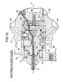
- a casing 11 of the expander M is formed from a casing main body 12, a front cover 15 fitted via a seal 13 in a front opening of the casing main body 12 and joined thereto via a plurality of bolts 14, and a rear cover 18 fitted via a seal 16 in a rear opening of the casing main body 12 and joined thereto via a plurality of bolts 17.
- An oil pan 19 abuts against a lower opening of the casing main body 12 via a seal 20 and is joined thereto via a plurality of bolts 21. Furthermore, a breather chamber dividing wall 23 is superimposed on an upper surface of the casing main body 12 via a seal 22 (see FIG. 12), a breather chamber cover 25 is further superimposed on an upper surface of the breather chamber dividing wall 23 via a seal 24 (see FIG. 12), and they are together secured to the casing main body 12 by means of a plurality of bolts 26.
- a rotor 27 and an output shaft 28 that can rotate around an axis L extending in the fore-and-aft direction in the center of the casing 11 are united by welding.
- a rear part of the rotor 27 is rotatably supported in the casing main body 12 via an angular ball bearing 29 and a seal 30, and a front part of the output shaft 28 is rotatably supported in the front cover 15 via an angular ball bearing 31 and a seal 32.
- a swash plate holder 36 is fitted via two seals 33 and 34 and a knock pin 35 in a rear face of the front cover 15 and fixed thereto via a plurality of bolts 37, and a swash plate 39 is rotatably supported in the swash plate holder 36 via an angular ball bearing 38.
- the rotational axis of the swash plate 39 is inclined relative to the axis L of the rotor 27 and the output shaft 28, and the angle of inclination is fixed.
- Seven sleeves 41 formed from members that are separate from the rotor 27 are arranged within the rotor 27 so as to surround the axis L at equal intervals in the circumferential direction.
- High-pressure pistons 43 are slidably fitted in high-pressure cylinders 42 formed at inner peripheries of the sleeves 41, which are supported by sleeve support bores 27a of the rotor 27.
- Hemispherical parts of the high-pressure pistons 43 projecting forward from forward end openings of the high-pressure cylinders 42 abut against and press against seven dimples 39a recessed in a rear surface of the swash plate 39.
- Heat resistant metal seals 44 are fitted between the rear ends of the sleeves 41 and the sleeve support bores 27a of the rotor 27, and a single set plate 45 retaining the front ends of the sleeves 41 in this state is fixed to a front surface of the rotor 27 by means of a plurality of bolts 46.
- the sleeve support bores 27a have a slightly larger diameter in the vicinity of their bases, thus forming a gap ⁇ (see FIG. 3) between themselves and the outer peripheries of the sleeves 41.
- the high-pressure pistons 43 include pressure rings 47 and oil rings 48 for sealing the sliding surfaces with the high-pressure cylinders 42, and the sliding range of the pressure rings 47 and the sliding range of the oil rings 48 are set so as not to overlap each other.
- tapered openings 45a widening toward the front are formed in the set plate 45.
- the sliding range of the pressure rings 47 and the sliding range of the oil rings 48 are set so as not to overlap each other, oil attached to the inner walls of the high-pressure cylinders 42 against which the oil rings 48 slide will not be taken into high-pressure operating chambers 82 due to sliding of the pressure rings 47, thereby reliably preventing the oil from contaminating the steam.
- the high-pressure pistons 43 have a slightly smaller diameter part between the pressure rings 47 and the oil rings 48 (see FIG. 3), thereby effectively preventing the oil attached to the sliding surfaces of the oil rings 48 from moving to the sliding surfaces of the pressure rings 47.
- the high-pressure cylinders 42 are formed by fitting the seven sleeves 41 in the sleeve support bores 27a of the rotor 27, a material having excellent thermal conductivity, heat resistance, abrasion resistance, strength, etc. can be selected for the sleeves 41. This not only improves the performance and the reliability, but also machining becomes easy compared with a case in which the high-pressure cylinders 42 are directly machined in the rotor 27, and the machining precision also increases. When any one of the sleeves 41 is worn or damaged, it is possible to exchange only the sleeve 41 with an abnormality, without exchanging the entire rotor 27, and this is economical.
- the gap ⁇ is formed between the outer periphery of the sleeves 41 and the rotor 27 by slightly enlarging the diameter of the sleeve support bores 27a in the vicinity of the base, even when the rotor 27 is thermally deformed by the high-temperature, high-pressure steam supplied to the high-pressure operating chambers 82, this is prevented from affecting the sleeves 41, thereby preventing the high-pressure cylinders 42 from distorting.
- the seven high-pressure cylinders 42 and the seven high-pressure pistons 43 fitted therein form a first group of axial piston cylinders 49.
- Seven low-pressure cylinders 50 are arranged at circumferentially equal intervals on the outer peripheral part of the rotor 27 so as to surround the axis L and the radially outer side of the high-pressure cylinders 42.
- These low-pressure cylinders 50 have a larger diameter than that of the high-pressure cylinders 42, and the pitch at which the low-pressure cylinders 50 are arranged in the circumferential direction is displaced by half a pitch relative to the pitch at which the high-pressure cylinders 42 are arranged in the circumferential direction.
- the seven low-pressure cylinders 50 have low-pressure pistons 51 slidably fitted thereinto, and these low-pressure pistons 51 are connected to the swash plate 39 via links 52. That is, spherical parts 52a at the front end of the links 52 are swingably supported in spherical bearings 54 fixed to the swash plate 39 via nuts 53, and spherical parts 52b at the rear end of the links 52 are swingably supported in spherical bearings 56 fixed to the low-pressure pistons 51 by clips 55.
- a pressure ring 78 and an oil ring 79 are fitted around the outer periphery of each of the low-pressure pistons 51 in the vicinity of the top surface thereof so as to adjoin each other. Since the sliding ranges of the pressure ring 78 and the oil ring 79 overlap each other, an oil film is formed on the sliding surface of the pressure ring 78, thus enhancing the sealing characteristics and the lubrication.
- the seven low-pressure cylinders 50 and the seven low-pressure pistons 41 fitted therein form a second group of axial piston cylinders 57.
- the front ends of the high-pressure pistons 43 of the first group of axial piston cylinders 49 are made in the form of hemispheres and are made to abut against the dimples 39a formed in the swash plate 39, it is unnecessary to connect the high-pressure pistons 43 to the swash plate 39 mechanically, thus reducing the number of parts and improving the ease of assembly.
- the low-pressure pistons 51 of the second group of axial piston cylinders 57 are connected to the swash plate 39 via the links 52 and their front and rear spherical bearings 54 and 56, and even when the temperature and the pressure of medium-temperature, medium-pressure steam supplied to the second group of axial piston cylinders 57 become insufficient and the pressure of low-pressure operating chambers 84 becomes negative, there is no possibility of the low-pressure pistons 51 becoming detached from the swash plate 39 and causing knocking or damage.
- the rotor 27 and the output shaft 28, which are united, are supported respectively by the angular ball bearing 29 provided on the casing main body 12 and the angular ball bearing 31 provided on the front cover 15, by adjusting the thickness of a shim 58 disposed between the casing main body 12 and the angular ball bearing 29 and the thickness of a shim 59 disposed between the front cover 15 and the angular ball bearing 31, the longitudinal position of the rotor 27 along the axis L can be adjusted.
- the relative positional relationship in the axis L direction between the high-pressure and low-pressure pistons 43 and 51 guided by the swash plate 39, and the high-pressure and low-pressure cylinders 42 and 50 provided in the rotor 27 can be changed, thereby adjusting the expansion ratio of the steam in the high-pressure and low-pressure operating chambers 82 and 84.
- a rotary valve 61 is housed in a circular cross-section recess 27b opening on the rear end surface of the rotor 27 and a circular cross-section recess 18a opening on a front surface of the rear cover 18.
- the rotary valve 61 which is disposed along the axis L, includes a rotary valve main body 62, a stationary valve plate 63, and a movable valve plate 64.
- the movable valve plate 64 is fixed to the rotor 27 via a knock pin 66 and a bolt 67 while being fitted to the base of the recess 27b of the rotor 27 via a gasket 65.
- the stationary valve plate 63 which abuts against the movable valve plate 64 via a flat sliding surface 68, is joined via a knock pin 69 to the rotary valve main body 62 so that there is no relative rotation therebetween.
- the movable valve plate 64 and the stationary valve plate 63 therefore rotate relative to each other on the sliding surface 68 in a state in which they are in intimate contact with each other.
- the stationary valve plate 63 and the movable valve plate 64 are made of a material having excellent durability, such as a super hard alloy or a ceramic, and the sliding surface 68 can be provided with or coated with a member having heat resistance, lubrication, corrosion resistance, and abrasion resistance.
- the rotary valve main body 62 is a stepped cylindrical member having a large diameter part 62a, a medium diameter part 62b, and a small diameter part 62c; an annular sliding member 70 fitted around the outer periphery of the large diameter part 62a is slidably fitted in the recess 27b of the rotor 27 via a cylindrical sliding surface 71, and the medium diameter part 62b and the small diameter part 62c are fitted in the recess 18a of the rear cover 18 via seals 72 and 73.
- the sliding member 70 is made of a material having excellent durability, such as a super hard alloy or a ceramic.
- a plurality of (for example, seven) preload springs 75 are supported in the rear cover 18 so as to surround the axis L, and the rotary valve main body 62, which has a step 62d between the medium diameter part 62b and the small diameter part 62c pressed by these preload springs 75, is biased forward so as to make the sliding surface 68 of the stationary valve plate 63 and the movable valve plate 64 come into intimate contact with each other.
- a pressure chamber 76 is defined between the bottom of the recess 18a of the rear cover 18 and the rear end surface of the small diameter part 62c of the rotary valve main body 62, and a steam supply pipe 77 connected so as to run though the rear cover 18 communicates with the pressure chamber 76.
- the rotary valve main body 62 is therefore biased forward by the steam pressure acting on the pressure chamber 76 in addition to the resilient force of the preload springs 75.
- a high-pressure stage steam intake route for supplying high-temperature, high-pressure steam to the first group of axial piston cylinders 49 is shown in FIG. 16 by a mesh pattern.
- a first steam passage P1 having its upstream end communicating with the pressure chamber 76, to which the high-temperature, high-pressure steam is supplied from the steam supply pipe 77, runs through the rotary valve main body 62, opens on the surface at which the rotary valve main body 62 is joined to the stationary valve plate 63, and communicates with a second steam passage P2 running through the stationary valve plate 63.
- the joining surface is equipped with a seal 81 (see FIG. 7 and FIG. 16), which seals the outer periphery of a connecting part between the first and second steam passages P1 and P2.
- Seven third steam passages P3 (see FIG. 5) and seven fourth steam passages P4 are formed respectively in the movable valve plate 64 and the rotor 27 at circumferentially equal intervals, and the downstream ends of the fourth steam passages P4 communicate with the seven high-pressure operating chambers 82 defined between the high-pressure cylinders 42 and the high-pressure pistons 43 of the first group of axial piston cylinders 49.
- an opening of the second steam passage P2 formed in the stationary valve plate 63 does not open evenly to the front and rear of the top dead center (TDC) of the high-pressure pistons 43, but opens displaced slightly forward in the direction of rotation of the rotor 27, which is shown by the arrow R.
- a high-pressure stage steam discharge route and a low-pressure stage steam intake route for discharging medium-temperature, medium-pressure steam from the first group of axial piston cylinders 49 and supplying it to the second group of axial piston cylinders 57 are shown in FIG. 17 by a mesh pattern.
- an arc-shaped fifth steam passage P5 (see FIG. 6) opens on a front surface of the stationary valve plate 63, and this fifth steam passage P5 communicates with a circular sixth steam passage P6 opening on a rear surface of the stationary valve plate 63 (see FIG. 7).
- the fifth steam passage P5 opens from a position displaced slightly forward in the direction of rotation of the rotor 27, which is shown by the arrow R, relative to the bottom dead center (BDC) of the high-pressure pistons 43 to a position slightly displaced backward in the rotational direction relative to the TDC.
- BDC bottom dead center
- a seventh steam passage P7 extending in the axis L direction and an eighth steam passage P8 extending in a substantially radial direction.
- the upstream end of the seventh steam passage P7 communicates with the downstream end of the sixth steam passage P6.
- the downstream end of the seventh steam passage P7 communicates with a tenth steam passage P10 running radially through the sliding member 70 via a ninth steam passage P9 within a coupling member 83 disposed so as to bridge between the rotary valve main body 62 and the sliding member 70.
- the tenth steam passage P10 communicates with the seven low-pressure operating chambers 84 defined between the low-pressure cylinders 50 and the low-pressure pistons 44 of the second group of axial piston cylinders 57 via seven eleventh steam passages P11 formed radially in the rotor 27.
- the outer periphery of a part where the sixth and seventh steam passages P6 and P7 are connected is sealed by equipping the joining surfaces with a seal 85 (see FIG. 7 and FIG. 17).
- Two seals 86 and 87 are disposed between the inner periphery of the sliding member 70 and the rotary valve main body 62, and a seal 88 is disposed between the outer periphery of the coupling member 83 and the sliding member 70.
- the interiors of the rotor 27 and the output shaft 28 are hollowed out to define a pressure regulating chamber 89, and this pressure regulating chamber 89 communicates with the eighth steam passage P8 via a twelfth steam passage P12 and a thirteenth steam passage P13 formed in the rotary valve main body 62, a fourteenth steam passage P14 formed in the stationary valve plate 63, and a fifteenth steam passage P15 running through the interior of the bolt 67.
- the pressure of the medium-temperature, medium-pressure steam discharged from the seven third steam passages P3 into the fifth steam passage P5 pulsates seven times per rotation of the rotor 27, but since the eighth steam passage P8, which is partway along the supply of the medium-temperature, medium-pressure steam to the second group of axial piston cylinders 57, is connected to the pressure regulating chamber 89, the pressure pulsations are dampened, steam at a constant pressure is supplied to the second group of axial piston cylinders 57, and the efficiency with which the low-pressure operating chambers 84 are charged with the steam can be enhanced.
- the pressure regulating chamber 89 is formed by utilizing dead spaces in the centers of the rotor 27 and the output shaft 28, the dimensions of the expander M are not increased, the hollowing out brings about a weight reduction effect and, moreover, since the outer periphery of the pressure regulating chamber 89 is surrounded by the first group of axial piston cylinders 49, which are operated by the high-temperature, high-pressure steam, there is no resultant heat loss in the medium-temperature, medium-pressure steam supplied to the second group of axial piston cylinders 57.
- the rotor 27 can be cooled by the medium-temperature, medium-pressure steam in the pressure regulating chamber 89, and the resulting heated medium-temperature, medium-pressure steam enables the output of the second group of axial piston cylinders 57 to be increased.
- FIG. 18 A steam discharge route for discharging the low-temperature, low-pressure steam from the second group of axial piston cylinders 57 is shown in FIG. 18 by a mesh pattern.
- an arc-shaped sixteenth steam passage P16 that can communicate with the seven eleventh steam passages P11 formed in the rotor 27 is cut out in the sliding surface 71 of the sliding member 70.
- This sixteenth steam passage P16 communicates with a seventeenth steam passage P17 that is cut out in an arc-shape in the outer periphery of the rotary valve main body 62.
- the sixteenth steam passage P16 opens from a position displaced slightly forward in the direction of rotation of the rotor 27, which is shown by the arrow R, relative to the BDC of the low-pressure pistons 51 to a position rotationally slightly backward relative to the TDC.
- This allows the eleventh steam passages P11 of the rotor 27 to communicate with the sixteenth steam passage P16 of the sliding member 70 over an angular range that starts from the BDC and does not overlap the tenth steam passage P10 (preferably, immediately before overlapping the tenth steam passage P10), and in this range the steam is discharged from the eleventh steam passages P11 to the sixteenth steam passage P16.
- the seventeenth steam passage P17 further communicates with a steam discharge chamber 90 formed between the rotary valve main body 62 and the rear cover 18 via an eighteenth steam passage P18 to a twentieth steam passage P20 formed within the rotary valve main body 62 and a cutout 18d of the rear cover 18, and this steam discharge chamber 90 communicates with a steam discharge hole 18c formed in the rear cover 18.
- the plurality of preload springs 75 apply a preset load to the rotary valve main body 62 and bias it forward in the axis L direction
- the high-temperature, high-pressure steam supplied from the steam supply pipe 77 to the pressure chamber 76 biases the rotary valve main body 62 forward in the axis L direction
- a surface pressure is generated on the sliding surface 68 between the stationary valve plate 63 and the movable valve plate 64 in response to the pressure of the high-temperature, high-pressure steam, and it is thus possible to prevent yet more effectively the steam from leaking past the sliding surface 68.
- a valve for supplying the medium-temperature, medium-pressure steam to the second group of axial piston cylinders 57 is formed on the cylindrical sliding surface 71 on the outer periphery of the rotary valve main body 62, since the pressure of the medium-temperature, medium-pressure steam passing through the valve is lower than the pressure of the high-temperature, high-pressure steam, the leakage of the steam can be suppressed to a practically acceptable level by maintaining a predetermined clearance without generating a surface pressure on the sliding surface 71.
- the first steam passage P1 through which the high-temperature, high-pressure steam passes, the seventh steam passage P7 and the eighth steam passage P8 through which the medium-temperature, medium-pressure steam passes, and the seventeenth steam passage P17 to the twentieth steam passage P20 through which the low-temperature, low-pressure steam passes are collectively formed within the rotary valve main body 62, not only can the steam temperature be prevented from dropping, but also the parts (for example, the seal 81) sealing the high-temperature, high-pressure steam can be cooled by the low-temperature, low-pressure steam, thus improving the durability.
- the rotary valve 61 can be attached to and detached from the casing main body 12 merely by removing the rear cover 18 from the casing main body 12, the ease of maintenance operations such as repair, cleaning, and replacement can be greatly improved. Furthermore, although the temperature of the rotary valve 61 through which the high-temperature, high-pressure steam passes becomes high, since the swash plate 39 and the output shaft 28, where lubrication by oil is required, are disposed on the opposite side to the rotary valve 61 relative to the rotor 27, the oil is prevented from being heated by the heat of the rotary valve 61 when it is at high temperature, which would degrade the performance in lubricating the swash plate 39 and the output shaft 28. Moreover, the oil can exhibit a function of cooling the rotary valve 61, thus preventing overheating.
- Provided within the lower breather chamber 101 so as to project upward are three dividing walls 12c to 12e having their upper ends in contact with a lower surface of the breather chamber dividing wall 23.
- the through hole 12b opens at one end of a labyrinth formed by these dividing walls 12c to 12e, and four oil return holes 12f running through the upper wall 12a are formed partway along the route to the other end of the labyrinth.
- the oil return holes 12f are formed at the lowest position of the lower breather chamber 101 (see FIG. 14), and the oil condensed within the lower breather chamber 101 can therefore be reliably returned to the lubrication chamber 102.
- An upper breather chamber 103 is defined between the breather chamber dividing wall 23 and the breather chamber cover 25, and this upper breather chamber 103 communicates with the lower breather chamber 101 via four through holes 23a and 23b running through the breather chamber dividing wall 23 and projecting in a chimney-shape within the upper breather chamber 103.
- a recess 12g is formed in the upper wall 12a of the casing main body 12 at a position below a condensed water return hole 23c running through the breather chamber dividing wall 23, and the periphery of the recess 12g is sealed by a seal 104.
- first breather passage B1 formed in the breather chamber dividing wall 23 opens at mid height in the upper breather chamber 103.
- the other end of the first breather passage B1 communicates with the steam discharge chamber 90 via a second breather passage B2 formed in the casing main body 12 and a third breather passage B3 formed in the rear cover 18.
- the recess 12g which is formed in the upper wall 12a, communicates with the steam discharge chamber 90 via a fourth breather passage B4 formed in the casing main body 12 and the third breather passage B3.
- the outer periphery of a part providing communication between the first breather passage B1 and the second breather passage B2 is sealed by a seal 105.
- a coupling 106 communicating with the lower breather chamber 101 and a coupling 107 communicating with the oil pan 19 are connected together by a transparent oil level gauge 108, and the oil level within the lubrication chamber 102 can be checked from the outside by the oil level of this oil level gauge 108. That is, the lubrication chamber 102 has a sealed structure, it is difficult to insert an oil level gauge from the outside from the viewpoint of maintaining sealing characteristics, and the structure will inevitably become complicated. However, this oil level gauge 108 enables the oil level to be checked easily from the outside while maintaining the lubrication chamber 102 in a sealed state.
- high-temperature, high-pressure steam generated by heating water in an evaporator is supplied to the pressure chamber 76 of the expander M via the steam supply pipe 77, and reaches the sliding surface 68 with the movable valve plate 64 via the first steam passage P1 formed in the rotary valve main body 62 of the rotary valve 61 and the second steam passage P2 formed in the stationary valve plate 63 integral with the rotary valve main body 62.
- the second steam passage P2 opening on the sliding surface 68 communicates momentarily with the third steam passages P3 formed in the movable valve plate 64 rotating integrally with the rotor 27, and the high-temperature, high-pressure steam is supplied, via the fourth steam passage P4 formed in the rotor 27, from the third steam passages P3 to, among the seven high-pressure operating chambers 82 of the first group of axial piston cylinders 49, the high-pressure operating chamber 82 that is present at the top dead center.
- the high-temperature, high-pressure steam expands within the high-pressure operating chamber 82 and causes the high-pressure piston 43 fitted in the high-pressure cylinder 42 of the sleeve 41 to be pushed forward from top dead center toward bottom dead center, and the front end of the high-pressure piston 43 presses against the dimple 39a of the swash plate 39.
- the reaction force that the high-pressure pistons 43 receive from the swash plate 39 gives a rotational torque to the rotor 27.
- the high-temperature, high-pressure steam is supplied into a fresh high-pressure operating chamber 82, thus continuously rotating the rotor 27.
- the medium-temperature, medium-pressure steam pushed out of the high-pressure operating chamber 82 is supplied to the eleventh steam passage P11 communicating with the low-pressure operating chamber 84 that, among the second group of axial piston cylinders 57, has reached top dead center accompanying rotation of the rotor 27, via the fourth steam passage P4 of the rotor 27, the third steam passage P3 of the movable valve plate 64, the sliding surface 68, the fifth steam passage P5 and the sixth steam passage P6 of the stationary valve plate 63, the seventh steam passage P7 to the tenth steam passage P10 of the rotary valve main body 62, and the sliding surface 71.
- the low-pressure piston 51 fitted in the low-pressure cylinder 50 is pushed forward from top dead center toward bottom dead center, and the link 52 connected to the low-pressure piston 51 presses against the swash plate 39.
- the pressure force of the low-pressure piston 51 is converted into a rotational force of the swash plate 39 via the link 52, and this rotational force transmits a rotational torque from the high-pressure piston 43 to the rotor 27 via the dimple 39a of the swash plate 39.
- the rotational torque is transmitted to the rotor 27, which rotates synchronously with the swash plate 39.
- the link 52 carries out a function of maintaining a connection between the low-pressure piston 51 and the swash plate 39, and it is arranged that the rotational torque due to the expansion is transmitted from the high-pressure piston 43 to the rotor 27 rotating synchronously with the swash plate 39 via the dimples 39a of the swash plate 39 as described above.
- the medium-temperature, medium-pressure steam is supplied into a fresh low-pressure operating chamber 84, thus continuously rotating the rotor 27.
- the pressure of the medium-temperature, medium-pressure steam discharged from the high-pressure operating chambers 82 of the first group of axial piston cylinders 49 pulsates seven times for each revolution of the rotor 27, but by damping these pulsations by the pressure regulating chamber 89 steam at a constant pressure can be supplied to the second group of axial piston cylinders 57, thereby enhancing the efficiency with which the low-pressure operating chambers 84 are charged with the steam.
- axial type expanders characteristically have a high space efficiency compared with radial type expanders
- the space efficiency can be further enhanced.
- the first group of axial piston cylinders 49 which are required to have only a small diameter because they are operated by high-pressure steam having a small volume, are arranged on the radially inner side
- the second group of axial piston cylinders 57 which are required to have a large diameter because they are operated by low-pressure steam having a large volume, are arranged on the radially outer side, the space can be utilized effectively, thus making the expander M still smaller.
- the cylinders 42 and 50 and the pistons 43 and 51 that are used have circular cross sections, which enables machining to be carried out with high precision, the amount of steam leakage can be reduced in comparison with a case in which vanes are used, and a yet higher output can thus be anticipated.
- the first group of axial piston cylinders 49 operated by high-temperature steam are arranged on the radially inner side
- the second group of axial piston cylinders 57 operated by low-temperature steam are arranged on the radially outer side
- the difference in temperature between the second group of axial piston cylinders 57 and the outside of the casing 11 can be minimized, the amount of heat released outside the casing 11 can be minimized, and the efficiency of the expander M can be enhanced.
- the heat escaping from the high-temperature first group of axial piston cylinders 49 on the radially inner side can be recovered by the low-temperature second group of axial piston cylinders 57 on the radially outer side, the efficiency of the expander M can be further enhanced.
- the sliding surface 68 on the high-pressure side is present deeper within the recess 27b of the rotor 27 than the sliding surface 71 on the low-pressure side, the difference in pressure between the outside of the casing 11 and the sliding surface 71 on the low-pressure side can be minimized, the amount of leakage of steam from the sliding surface 71 on the low-pressure side can be reduced and, moreover, the pressure of steam leaking from the sliding surface 68 on the high-pressure side can be recovered by the sliding surface 71 on the low-pressure side and utilized effectively.
- the oil stored in the oil pan 19 is stirred and splashed by the rotor 27 rotating within the lubrication chamber 102 of the casing 11, thereby lubricating a sliding section between the high-pressure cylinders 42 and the high-pressure pistons 43, a sliding section between the low-pressure cylinders 50 and the low-pressure pistons 51, the angular ball bearing 31 supporting the output shaft 28, the angular ball bearing 29 supporting the rotor 27, the angular ball bearing 38 supporting the swash plate 39, a sliding section between the high-pressure pistons 43 and the swash plate 39, the spherical bearings 54 and 56 at opposite ends of the links 52, etc.
- the interior of the lubrication chamber 102 is filled with oil mist generated by splashing due to stirring of the oil, and oil vapor generated by vaporization due to heating by a high-temperature section of the rotor 27, and this is mixed with steam leaking into the lubrication chamber 102 from the high-pressure operating chambers 82 and low-pressure operating chambers 84.
- the pressure of the lubrication chamber 102 becomes higher than the pressure of the steam discharge chamber 90 due to leakage of the steam, the mixture of oil content and steam flows through the through hole 12b formed in the upper wall 12a of the casing main body 12 into the lower breather chamber 101.
- the interior of the lower breather chamber 101 has a labyrinth structure due to the dividing walls 12c to 12e; the oil that condenses while passing therethrough drops through the four oil return holes 12f formed in the upper wall 12a of the casing main body 12, and is returned to the lubrication chamber 102.
- the steam from which the oil content has been removed passes through the four through holes 23a and 23b of the breather chamber dividing wall 23, flows into the upper breather chamber 103, and condenses by losing its heat to the outside air via the breather chamber cover 25, which defines an upper wall of the upper breather chamber 103.
- Water that has condensed within the upper breather chamber 103 passes through the condensed water return hole 23c formed in the breather chamber dividing wall 23 and drops into the recess 12g without flowing into the four through holes 23a, 23b projecting in a chimney-shape within the upper breather chamber 103, and is discharged therefrom into the steam discharge chamber 90 via the fourth breather passage B4 and the third breather passage B3.
- the amount of condensed water returned into the steam discharge chamber 90 corresponds to the amount of steam that has leaked from the high-pressure operating chambers 82 and the low-pressure operating chambers 84 into the lubrication chamber 102. Furthermore, since the steam discharge chamber 90 and the upper breather chamber 103 always communicate with each other via the first steam passage B1 to the third steam passage B3, which function as pressure equilibration passages, pressure equilibrium between the steam discharge chamber 90 and the lubrication chamber 102 can be maintained.
- the pressure of the lubrication chamber 102 becomes lower than the pressure of the steam discharge chamber 90, the steam in the steam discharge chamber 90 might be expected to flow into the lubrication chamber 102 via the third breather passage B3, the second breather passage B2, the first breather passage B1, the upper breather chamber 103, and the lower breather chamber 101, but after completion of the warming-up, because of the leakage of steam into the lubrication chamber 102, the pressure of the lubrication chamber 102 becomes higher than the pressure of the steam discharge chamber 90, and the above-mentioned oil and steam separation is started.
- FIG. 19 shows a sliding surface 68 of a stationary valve plate 63 and corresponds to FIG. 6, which shows the first embodiment.
- the resilient force of preset springs 75 and the pressure of high-temperature, high-pressure steam acting on a pressure chamber 76 give a sealing surface pressure to the sliding surface 68, but it is difficult to secure a uniform sealing surface pressure over the entire area of the sliding surface 68. This is because the high-temperature, high-pressure steam is supplied to a second steam passage P2 and third steam passages P3 passing through the sliding surface 68, and this high-temperature, high-pressure steam acts to detach the stationary valve plate 63 from a movable valve plate 64 and thereby reduce the sealing surface pressure.
- medium-temperature, medium-pressure steam is supplied to a fifth steam passage P5 and the third steam passages P3 running through the sliding surface 68, and since the pressure thereof is lower than the pressure of the high-temperature, high-pressure steam, its action of detaching the sliding surface 68 and thereby reducing the sealing surface pressure is also small.
- the steam pressures of the second steam passage P2, the third steam passages P, and the fifth steam passage P5 apply an imbalanced load to the sliding surface 68, thus causing the sealing performance of the sliding surface 68 to deteriorate.
- annular first pressure channel G1 is machined in the sliding surface 68 of the stationary valve plate 63 so as to surround the outer periphery of a fourteenth steam passage P14 passing along the axis L, the first pressure channel G1 being made to communicate with the fifth steam passage P5 through which the medium-temperature, medium-pressure steam passes, and an arc-shaped second pressure channel G2 is machined so as to surround the outer periphery of the first pressure channel G1, the second pressure channel G2 being made to communicate with the second steam passage P2 through which the high-temperature, high-pressure steam passes.
- the actions of the first and second pressure channels G1 and G2 ease the uneven sealing surface pressure on the sliding surface 68, and deterioration of the sealing characteristics and generation of friction due to uneven contact with the sliding surface 68 can be prevented. Furthermore, when the steam leaking from the high-pressure second pressure channel G2 flows into the low-pressure first pressure channel G1, an abrasive powder is discharged into the first pressure channel G1, and an effect of preventing it from flowing into the high-pressure operating chambers 82 is thus exhibited. Moreover, the steam is uniformly distributed on the sliding surface 68, where lubrication by oil cannot be expected, thereby improving the lubrication performance.
- the third embodiment is a modification of the second embodiment; a second pressure channel G2 communicating with a second steam passage P2 through which high-temperature, high-pressure steam passes is omitted, and only a first pressure channel G1 communicating with a fifth steam passage P15 through which medium-temperature, medium-pressure steam passes is provided.
- a second pressure channel G2 communicating with a second steam passage P2 through which high-temperature, high-pressure steam passes is omitted, and only a first pressure channel G1 communicating with a fifth steam passage P15 through which medium-temperature, medium-pressure steam passes is provided.
- first group of axial piston cylinders 49 and the second group of axial piston cylinders 57 are provided, but three or more sets of groups of axial piston cylinders may be provided.
- the expander related to the present invention can be applied desirably to a Rankine cycle system, but it can be applied to any purpose and is not limited to the Rankine cycle system.
Applications Claiming Priority (3)
| Application Number | Priority Date | Filing Date | Title |
|---|---|---|---|
| JP2001061423 | 2001-03-06 | ||
| JP2001061423 | 2001-03-06 | ||
| PCT/JP2002/001987 WO2002077415A1 (fr) | 2001-03-06 | 2002-03-05 | Machine de detente |
Publications (3)
| Publication Number | Publication Date |
|---|---|
| EP1367218A1 true EP1367218A1 (de) | 2003-12-03 |
| EP1367218A4 EP1367218A4 (de) | 2004-11-03 |
| EP1367218B1 EP1367218B1 (de) | 2006-09-13 |
Family
ID=18920720
Family Applications (1)
| Application Number | Title | Priority Date | Filing Date |
|---|---|---|---|
| EP02701713A Expired - Lifetime EP1367218B1 (de) | 2001-03-06 | 2002-03-05 | Expansionsmaschine |
Country Status (8)
| Country | Link |
|---|---|
| US (1) | US7406911B2 (de) |
| EP (1) | EP1367218B1 (de) |
| KR (1) | KR20030078955A (de) |
| CN (1) | CN1494632A (de) |
| BR (1) | BR0207848A (de) |
| CA (1) | CA2439600A1 (de) |
| DE (1) | DE60214685T8 (de) |
| WO (1) | WO2002077415A1 (de) |
Cited By (2)
| Publication number | Priority date | Publication date | Assignee | Title |
|---|---|---|---|---|
| WO2005057009A1 (de) * | 2003-12-15 | 2005-06-23 | Brueninghaus Hydromatik Gmbh | Axialkolbenmaschine zum unabhängigen fördern in mehrere hydraulische kreislaüfe |
| WO2005073511A1 (de) * | 2004-01-29 | 2005-08-11 | Enginion Ag | Ventilgesteuerte expansionsmachine |
Families Citing this family (11)
| Publication number | Priority date | Publication date | Assignee | Title |
|---|---|---|---|---|
| US7111457B1 (en) * | 2004-06-12 | 2006-09-26 | Hydro-Gear Limited Partnership | Diagnostic system for a hydrostatic transmission or transaxle |
| DE102006058556A1 (de) * | 2006-12-08 | 2008-06-12 | Iav Gmbh Ingenieurgesellschaft Auto Und Verkehr | Anordnung von Sekundärantrieben, die in Wirkverbindung mit einer Kardanwelle stehen |
| DE102008047275C5 (de) | 2007-12-13 | 2013-07-11 | Renate Geipel | Expansionsmaschine |
| JP4833237B2 (ja) * | 2008-03-03 | 2011-12-07 | 川崎重工業株式会社 | 電動機一体型油圧モータ |
| KR200458096Y1 (ko) * | 2009-09-15 | 2012-01-18 | 한일이화주식회사 | 열융착기 |
| CN103644295B (zh) * | 2013-12-15 | 2015-11-18 | 中国科学院工程热物理研究所 | 一种单阀膨胀机的活塞系统 |
| DE102014209892A1 (de) * | 2014-05-23 | 2015-11-26 | Mahle International Gmbh | Axialkolbenmaschine |
| DE102014210774B4 (de) * | 2014-06-05 | 2020-03-26 | Danfoss Power Solutions Gmbh & Co. Ohg | Hydraulischer Antrieb mit einer verstellbaren hydraulischen Axialkolbenmaschine in Dry-Case Bauweise |
| KR101604764B1 (ko) | 2014-08-27 | 2016-03-18 | 주식회사 엔진텍 | 사판식 팽창기 |
| KR101603091B1 (ko) | 2014-09-11 | 2016-03-14 | 주식회사 엔진텍 | 사판식 팽창기의 윤활시스템 |
| JP6688724B2 (ja) * | 2016-03-28 | 2020-04-28 | 株式会社神戸製鋼所 | 液圧回転機 |
Citations (4)
| Publication number | Priority date | Publication date | Assignee | Title |
|---|---|---|---|---|
| GB240107A (en) * | 1925-06-26 | 1925-09-24 | Adrianus Anthony Wilton Van Re | Improvements in steam or other fluid engines |
| GB328182A (en) * | 1929-08-26 | 1930-04-24 | Nicolas Herzmark | Improvements in air compressors |
| JPH10184532A (ja) * | 1996-12-26 | 1998-07-14 | Daikin Ind Ltd | 可変容量形ピストンポンプ |
| US6074174A (en) * | 1998-01-15 | 2000-06-13 | Thomas Industries Inc. | Fluid pumping apparatus |
Family Cites Families (20)
| Publication number | Priority date | Publication date | Assignee | Title |
|---|---|---|---|---|
| US1840864A (en) * | 1920-11-24 | 1932-01-12 | Elwyn M Rayburn | Power transmission apparatus |
| US2520632A (en) * | 1945-03-22 | 1950-08-29 | Torq Electric Mfg Company | Hydraulic pump or motor |
| US2445281A (en) | 1945-10-04 | 1948-07-13 | Charles H Rystrom | Hydraulic pump |
| GB1013041A (en) * | 1962-05-07 | 1965-12-15 | Council Scient Ind Res | Improvements in liquid pressure engines |
| ES285781A1 (es) | 1962-06-08 | 1963-08-16 | Cambi Idraulici Badalini Spa | Cambio hidráulico continuo de recuperación de energía, particularmente adaptado para vehículos automóviles |
| DE1500457A1 (de) | 1965-08-18 | 1969-07-10 | Joh Neukirch | Axialkolbengetriebe |
| US3364679A (en) * | 1965-10-21 | 1968-01-23 | Chrysler Corp | Hydrostatic transmission |
| DE1655051A1 (de) | 1966-06-15 | 1971-03-25 | Cambi Idraulici Badalini Spa | Hydraulisches Geschwindigkeitswechselgetriebe |
| IT1082968B (it) * | 1977-04-05 | 1985-05-21 | Gherner Lidio | Motore idraulico a pistoni assiali |
| JPS5776357A (en) | 1980-10-31 | 1982-05-13 | Honda Motor Co Ltd | Hydraulic stepless transmission |
| DE3841382C1 (de) * | 1988-12-08 | 1990-03-15 | Hydromatik Gmbh, 7915 Elchingen, De | |
| JPH02283870A (ja) * | 1989-04-05 | 1990-11-21 | Zahnradfab Friedrichshafen Ag | 軸方向ピストンポンプ |
| JPH03242473A (ja) * | 1990-02-15 | 1991-10-29 | Daikin Ind Ltd | アキシャルピストン機械 |
| JP2874300B2 (ja) | 1990-07-27 | 1999-03-24 | ダイキン工業株式会社 | 多連ピストンポンプ |
| JP3031154B2 (ja) * | 1994-02-28 | 2000-04-10 | 株式会社日立製作所 | 等速継手 |
| JPH1047243A (ja) | 1996-07-29 | 1998-02-17 | Nippon Soken Inc | 斜板型圧縮機 |
| JP2927248B2 (ja) * | 1996-08-08 | 1999-07-28 | 株式会社日立製作所 | 等速継手 |
| JP3724929B2 (ja) * | 1997-09-11 | 2005-12-07 | 本田技研工業株式会社 | 斜板式油圧装置 |
| JP4134381B2 (ja) * | 1998-06-22 | 2008-08-20 | ダイキン工業株式会社 | 可変容量形ピストンポンプ |
| JP2000320453A (ja) | 1999-03-05 | 2000-11-21 | Honda Motor Co Ltd | 膨脹機能および圧縮機能を持つ回転式流体機械およびベーン式流体機械 |
-
2002
- 2002-03-05 EP EP02701713A patent/EP1367218B1/de not_active Expired - Lifetime
- 2002-03-05 CA CA002439600A patent/CA2439600A1/en not_active Abandoned
- 2002-03-05 KR KR10-2003-7011374A patent/KR20030078955A/ko active IP Right Grant
- 2002-03-05 CN CNA02806075XA patent/CN1494632A/zh active Pending
- 2002-03-05 DE DE60214685T patent/DE60214685T8/de not_active Expired - Fee Related
- 2002-03-05 WO PCT/JP2002/001987 patent/WO2002077415A1/ja active IP Right Grant
- 2002-03-05 US US10/469,762 patent/US7406911B2/en not_active Expired - Fee Related
- 2002-03-05 BR BR0207848-1A patent/BR0207848A/pt not_active IP Right Cessation
Patent Citations (4)
| Publication number | Priority date | Publication date | Assignee | Title |
|---|---|---|---|---|
| GB240107A (en) * | 1925-06-26 | 1925-09-24 | Adrianus Anthony Wilton Van Re | Improvements in steam or other fluid engines |
| GB328182A (en) * | 1929-08-26 | 1930-04-24 | Nicolas Herzmark | Improvements in air compressors |
| JPH10184532A (ja) * | 1996-12-26 | 1998-07-14 | Daikin Ind Ltd | 可変容量形ピストンポンプ |
| US6074174A (en) * | 1998-01-15 | 2000-06-13 | Thomas Industries Inc. | Fluid pumping apparatus |
Non-Patent Citations (1)
| Title |
|---|
| See also references of WO02077415A1 * |
Cited By (3)
| Publication number | Priority date | Publication date | Assignee | Title |
|---|---|---|---|---|
| WO2005057009A1 (de) * | 2003-12-15 | 2005-06-23 | Brueninghaus Hydromatik Gmbh | Axialkolbenmaschine zum unabhängigen fördern in mehrere hydraulische kreislaüfe |
| US7458312B2 (en) | 2003-12-15 | 2008-12-02 | Brueninghaus Hydromatik, Gmbh | Axial piston machine for independent delivery into a plurality of hydraulic circuits |
| WO2005073511A1 (de) * | 2004-01-29 | 2005-08-11 | Enginion Ag | Ventilgesteuerte expansionsmachine |
Also Published As
| Publication number | Publication date |
|---|---|
| DE60214685D1 (de) | 2006-10-26 |
| EP1367218B1 (de) | 2006-09-13 |
| DE60214685T8 (de) | 2007-05-16 |
| EP1367218A4 (de) | 2004-11-03 |
| US7406911B2 (en) | 2008-08-05 |
| KR20030078955A (ko) | 2003-10-08 |
| US20040144088A1 (en) | 2004-07-29 |
| CN1494632A (zh) | 2004-05-05 |
| DE60214685T2 (de) | 2007-01-04 |
| CA2439600A1 (en) | 2002-10-03 |
| BR0207848A (pt) | 2004-06-22 |
| WO2002077415A1 (fr) | 2002-10-03 |
Similar Documents
| Publication | Publication Date | Title |
|---|---|---|
| US6910333B2 (en) | Rankine cycle device of internal combustion engine | |
| EP1367218B1 (de) | Expansionsmaschine | |
| US6948316B2 (en) | Rankine cycle system | |
| EP1367219B1 (de) | Hydraulische rotationsmaschine | |
| EP1367220B1 (de) | Hydraulische rotationsmaschine | |
| US6846163B2 (en) | Rotary fluid machine having rotor segments on the outer periphery of a rotor core | |
| EP1469162A1 (de) | Rotationsfluidmaschine | |
| JP3923331B2 (ja) | 膨張機 | |
| JP4104351B2 (ja) | 膨張機 | |
| US20040216602A1 (en) | Rotating fluid machine | |
| US20040216601A1 (en) | Rotating fluid machine | |
| US20050089410A1 (en) | Rotating fluid machine | |
| US20050158181A1 (en) | Expansion engine | |
| JP2005171954A (ja) | 回転流体機械 | |
| JP2003232202A (ja) | 回転式流体機械 | |
| JP2003232201A (ja) | 回転式流体機械 | |
| JP2005046760A (ja) | 分離装置 | |
| JP2004204766A (ja) | 回転流体機械 | |
| JP2003239703A (ja) | 回転式流体機械 |
Legal Events
| Date | Code | Title | Description |
|---|---|---|---|
| PUAI | Public reference made under article 153(3) epc to a published international application that has entered the european phase |
Free format text: ORIGINAL CODE: 0009012 |
|
| 17P | Request for examination filed |
Effective date: 20030909 |
|
| AK | Designated contracting states |
Kind code of ref document: A1 Designated state(s): AT BE CH CY DE DK ES FI FR GB GR IE IT LI LU MC NL PT SE TR |
|
| AX | Request for extension of the european patent |
Extension state: AL LT LV MK RO SI |
|
| A4 | Supplementary search report drawn up and despatched |
Effective date: 20040920 |
|
| 17Q | First examination report despatched |
Effective date: 20041122 |
|
| GRAP | Despatch of communication of intention to grant a patent |
Free format text: ORIGINAL CODE: EPIDOSNIGR1 |
|
| GRAS | Grant fee paid |
Free format text: ORIGINAL CODE: EPIDOSNIGR3 |
|
| GRAA | (expected) grant |
Free format text: ORIGINAL CODE: 0009210 |
|
| AK | Designated contracting states |
Kind code of ref document: B1 Designated state(s): DE ES FR GB IT |
|
| PG25 | Lapsed in a contracting state [announced via postgrant information from national office to epo] |
Ref country code: IT Free format text: LAPSE BECAUSE OF FAILURE TO SUBMIT A TRANSLATION OF THE DESCRIPTION OR TO PAY THE FEE WITHIN THE PRESCRIBED TIME-LIMIT;WARNING: LAPSES OF ITALIAN PATENTS WITH EFFECTIVE DATE BEFORE 2007 MAY HAVE OCCURRED AT ANY TIME BEFORE 2007. THE CORRECT EFFECTIVE DATE MAY BE DIFFERENT FROM THE ONE RECORDED. Effective date: 20060913 |
|
| REG | Reference to a national code |
Ref country code: GB Ref legal event code: FG4D |
|
| REF | Corresponds to: |
Ref document number: 60214685 Country of ref document: DE Date of ref document: 20061026 Kind code of ref document: P |
|
| PG25 | Lapsed in a contracting state [announced via postgrant information from national office to epo] |
Ref country code: ES Free format text: LAPSE BECAUSE OF FAILURE TO SUBMIT A TRANSLATION OF THE DESCRIPTION OR TO PAY THE FEE WITHIN THE PRESCRIBED TIME-LIMIT Effective date: 20061224 |
|
| EN | Fr: translation not filed | ||
| PLBE | No opposition filed within time limit |
Free format text: ORIGINAL CODE: 0009261 |
|
| STAA | Information on the status of an ep patent application or granted ep patent |
Free format text: STATUS: NO OPPOSITION FILED WITHIN TIME LIMIT |
|
| 26N | No opposition filed |
Effective date: 20070614 |
|
| GBPC | Gb: european patent ceased through non-payment of renewal fee |
Effective date: 20070305 |
|
| PG25 | Lapsed in a contracting state [announced via postgrant information from national office to epo] |
Ref country code: DE Free format text: LAPSE BECAUSE OF NON-PAYMENT OF DUE FEES Effective date: 20071002 |
|
| PG25 | Lapsed in a contracting state [announced via postgrant information from national office to epo] |
Ref country code: FR Free format text: LAPSE BECAUSE OF FAILURE TO SUBMIT A TRANSLATION OF THE DESCRIPTION OR TO PAY THE FEE WITHIN THE PRESCRIBED TIME-LIMIT Effective date: 20070518 Ref country code: GB Free format text: LAPSE BECAUSE OF NON-PAYMENT OF DUE FEES Effective date: 20070305 |
|
| PG25 | Lapsed in a contracting state [announced via postgrant information from national office to epo] |
Ref country code: FR Free format text: LAPSE BECAUSE OF FAILURE TO SUBMIT A TRANSLATION OF THE DESCRIPTION OR TO PAY THE FEE WITHIN THE PRESCRIBED TIME-LIMIT Effective date: 20060913 |