EP1363794B1 - Seitlich neigbares dreiradfahrzeug - Google Patents
Seitlich neigbares dreiradfahrzeug Download PDFInfo
- Publication number
- EP1363794B1 EP1363794B1 EP01912125A EP01912125A EP1363794B1 EP 1363794 B1 EP1363794 B1 EP 1363794B1 EP 01912125 A EP01912125 A EP 01912125A EP 01912125 A EP01912125 A EP 01912125A EP 1363794 B1 EP1363794 B1 EP 1363794B1
- Authority
- EP
- European Patent Office
- Prior art keywords
- vehicle
- control unit
- wheels
- sensors
- automatic device
- Prior art date
- Legal status (The legal status is an assumption and is not a legal conclusion. Google has not performed a legal analysis and makes no representation as to the accuracy of the status listed.)
- Expired - Lifetime
Links
- 239000000725 suspension Substances 0.000 title 1
- 238000005096 rolling process Methods 0.000 claims abstract description 14
- 230000007246 mechanism Effects 0.000 claims abstract description 12
- 238000000034 method Methods 0.000 claims abstract description 3
- 230000008569 process Effects 0.000 claims abstract description 3
- 230000001133 acceleration Effects 0.000 claims description 3
- 230000000694 effects Effects 0.000 claims description 3
- 239000000446 fuel Substances 0.000 claims description 2
- 230000008901 benefit Effects 0.000 abstract description 5
- 238000010586 diagram Methods 0.000 description 2
- 239000011159 matrix material Substances 0.000 description 2
- 239000000243 solution Substances 0.000 description 2
- 230000003068 static effect Effects 0.000 description 2
- 229910000831 Steel Inorganic materials 0.000 description 1
- 230000009471 action Effects 0.000 description 1
- 239000004020 conductor Substances 0.000 description 1
- 230000007717 exclusion Effects 0.000 description 1
- 238000002347 injection Methods 0.000 description 1
- 239000007924 injection Substances 0.000 description 1
- 238000011089 mechanical engineering Methods 0.000 description 1
- 230000004044 response Effects 0.000 description 1
- 230000000284 resting effect Effects 0.000 description 1
- 230000002441 reversible effect Effects 0.000 description 1
- 239000010959 steel Substances 0.000 description 1
- 230000007704 transition Effects 0.000 description 1
Images


Classifications
-
- B—PERFORMING OPERATIONS; TRANSPORTING
- B62—LAND VEHICLES FOR TRAVELLING OTHERWISE THAN ON RAILS
- B62K—CYCLES; CYCLE FRAMES; CYCLE STEERING DEVICES; RIDER-OPERATED TERMINAL CONTROLS SPECIALLY ADAPTED FOR CYCLES; CYCLE AXLE SUSPENSIONS; CYCLE SIDE-CARS, FORECARS, OR THE LIKE
- B62K5/00—Cycles with handlebars, equipped with three or more main road wheels
- B62K5/10—Cycles with handlebars, equipped with three or more main road wheels with means for inwardly inclining the vehicle body on bends
-
- B—PERFORMING OPERATIONS; TRANSPORTING
- B60—VEHICLES IN GENERAL
- B60G—VEHICLE SUSPENSION ARRANGEMENTS
- B60G17/00—Resilient suspensions having means for adjusting the spring or vibration-damper characteristics, for regulating the distance between a supporting surface and a sprung part of vehicle or for locking suspension during use to meet varying vehicular or surface conditions, e.g. due to speed or load
- B60G17/015—Resilient suspensions having means for adjusting the spring or vibration-damper characteristics, for regulating the distance between a supporting surface and a sprung part of vehicle or for locking suspension during use to meet varying vehicular or surface conditions, e.g. due to speed or load the regulating means comprising electric or electronic elements
- B60G17/016—Resilient suspensions having means for adjusting the spring or vibration-damper characteristics, for regulating the distance between a supporting surface and a sprung part of vehicle or for locking suspension during use to meet varying vehicular or surface conditions, e.g. due to speed or load the regulating means comprising electric or electronic elements characterised by their responsiveness, when the vehicle is travelling, to specific motion, a specific condition, or driver input
- B60G17/0162—Resilient suspensions having means for adjusting the spring or vibration-damper characteristics, for regulating the distance between a supporting surface and a sprung part of vehicle or for locking suspension during use to meet varying vehicular or surface conditions, e.g. due to speed or load the regulating means comprising electric or electronic elements characterised by their responsiveness, when the vehicle is travelling, to specific motion, a specific condition, or driver input mainly during a motion involving steering operation, e.g. cornering, overtaking
-
- B—PERFORMING OPERATIONS; TRANSPORTING
- B60—VEHICLES IN GENERAL
- B60G—VEHICLE SUSPENSION ARRANGEMENTS
- B60G17/00—Resilient suspensions having means for adjusting the spring or vibration-damper characteristics, for regulating the distance between a supporting surface and a sprung part of vehicle or for locking suspension during use to meet varying vehicular or surface conditions, e.g. due to speed or load
- B60G17/015—Resilient suspensions having means for adjusting the spring or vibration-damper characteristics, for regulating the distance between a supporting surface and a sprung part of vehicle or for locking suspension during use to meet varying vehicular or surface conditions, e.g. due to speed or load the regulating means comprising electric or electronic elements
- B60G17/017—Resilient suspensions having means for adjusting the spring or vibration-damper characteristics, for regulating the distance between a supporting surface and a sprung part of vehicle or for locking suspension during use to meet varying vehicular or surface conditions, e.g. due to speed or load the regulating means comprising electric or electronic elements characterised by their use when the vehicle is stationary, e.g. during loading, engine start-up or switch-off
-
- B—PERFORMING OPERATIONS; TRANSPORTING
- B60—VEHICLES IN GENERAL
- B60G—VEHICLE SUSPENSION ARRANGEMENTS
- B60G21/00—Interconnection systems for two or more resiliently-suspended wheels, e.g. for stabilising a vehicle body with respect to acceleration, deceleration or centrifugal forces
- B60G21/007—Interconnection systems for two or more resiliently-suspended wheels, e.g. for stabilising a vehicle body with respect to acceleration, deceleration or centrifugal forces means for adjusting the wheel inclination
-
- B—PERFORMING OPERATIONS; TRANSPORTING
- B60—VEHICLES IN GENERAL
- B60G—VEHICLE SUSPENSION ARRANGEMENTS
- B60G21/00—Interconnection systems for two or more resiliently-suspended wheels, e.g. for stabilising a vehicle body with respect to acceleration, deceleration or centrifugal forces
- B60G21/02—Interconnection systems for two or more resiliently-suspended wheels, e.g. for stabilising a vehicle body with respect to acceleration, deceleration or centrifugal forces permanently interconnected
- B60G21/04—Interconnection systems for two or more resiliently-suspended wheels, e.g. for stabilising a vehicle body with respect to acceleration, deceleration or centrifugal forces permanently interconnected mechanically
- B60G21/05—Interconnection systems for two or more resiliently-suspended wheels, e.g. for stabilising a vehicle body with respect to acceleration, deceleration or centrifugal forces permanently interconnected mechanically between wheels on the same axle but on different sides of the vehicle, i.e. the left and right wheel suspensions being interconnected
- B60G21/055—Stabiliser bars
- B60G21/0551—Mounting means therefor
- B60G21/0553—Mounting means therefor adjustable
- B60G21/0555—Mounting means therefor adjustable including an actuator inducing vehicle roll
-
- B—PERFORMING OPERATIONS; TRANSPORTING
- B62—LAND VEHICLES FOR TRAVELLING OTHERWISE THAN ON RAILS
- B62K—CYCLES; CYCLE FRAMES; CYCLE STEERING DEVICES; RIDER-OPERATED TERMINAL CONTROLS SPECIALLY ADAPTED FOR CYCLES; CYCLE AXLE SUSPENSIONS; CYCLE SIDE-CARS, FORECARS, OR THE LIKE
- B62K5/00—Cycles with handlebars, equipped with three or more main road wheels
- B62K5/02—Tricycles
- B62K5/027—Motorcycles with three wheels
-
- B—PERFORMING OPERATIONS; TRANSPORTING
- B62—LAND VEHICLES FOR TRAVELLING OTHERWISE THAN ON RAILS
- B62K—CYCLES; CYCLE FRAMES; CYCLE STEERING DEVICES; RIDER-OPERATED TERMINAL CONTROLS SPECIALLY ADAPTED FOR CYCLES; CYCLE AXLE SUSPENSIONS; CYCLE SIDE-CARS, FORECARS, OR THE LIKE
- B62K5/00—Cycles with handlebars, equipped with three or more main road wheels
- B62K5/02—Tricycles
- B62K5/05—Tricycles characterised by a single rear wheel
-
- B—PERFORMING OPERATIONS; TRANSPORTING
- B62—LAND VEHICLES FOR TRAVELLING OTHERWISE THAN ON RAILS
- B62K—CYCLES; CYCLE FRAMES; CYCLE STEERING DEVICES; RIDER-OPERATED TERMINAL CONTROLS SPECIALLY ADAPTED FOR CYCLES; CYCLE AXLE SUSPENSIONS; CYCLE SIDE-CARS, FORECARS, OR THE LIKE
- B62K5/00—Cycles with handlebars, equipped with three or more main road wheels
- B62K5/02—Tricycles
- B62K5/06—Frames for tricycles
-
- B—PERFORMING OPERATIONS; TRANSPORTING
- B62—LAND VEHICLES FOR TRAVELLING OTHERWISE THAN ON RAILS
- B62K—CYCLES; CYCLE FRAMES; CYCLE STEERING DEVICES; RIDER-OPERATED TERMINAL CONTROLS SPECIALLY ADAPTED FOR CYCLES; CYCLE AXLE SUSPENSIONS; CYCLE SIDE-CARS, FORECARS, OR THE LIKE
- B62K5/00—Cycles with handlebars, equipped with three or more main road wheels
- B62K5/08—Cycles with handlebars, equipped with three or more main road wheels with steering devices acting on two or more wheels
-
- B—PERFORMING OPERATIONS; TRANSPORTING
- B60—VEHICLES IN GENERAL
- B60G—VEHICLE SUSPENSION ARRANGEMENTS
- B60G2300/00—Indexing codes relating to the type of vehicle
- B60G2300/12—Cycles; Motorcycles
- B60G2300/122—Trikes
Definitions
- the present invention refers to a device for locking the banking, i.e. rolling motion, of a pair of rolling wheels in an engine and/or motor driven vehicle having three or more wheels.
- a rolling-wheel vehicle is a double track vehicle having two rolling wheels on the front axle and possibly also on the rear one. Their spindles are in fact attached to a first end portion of respective springs, whose second end portion is attached to the end portions of a rocker lever having its fulcrum hinged on to the frame along the longitudinal mid-plane of the vehicle.
- said springs do extend and contract in the same manner and this enables a moving vehicle to behave in the same way of a traditional two-wheeled motor-cycle, i.e. to be able to take a well-defined configuration of dynamic equilibrium.
- Suitable devices which are adapted to be actuated by the driver, are provided to lock the banking of the rocker lever and of the associated wheels so as to maintain the springs at a different elongation.
- the behaviour of the vehicle, when at a standstill or moving at a very low speed, is consequently much like a traditional four-wheeled motor-car, i.e. the vehicle is also permitted to have a configuration of static equilibrium.
- WO97/27071 From WO97/27071 is known a device for locking the tilting mechanism of the vehicle only at low speeds. However WO97/27071 does not teach to take into account at least a second parameter as input data from the control unit of the automatic device.
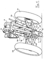
- FIG 1 only two steel tubes 1A, 1B which are a part of the loop frame and extend downwards in the front portion of the vehicle and the members 3A, 3B, 4 and 5 of a lattice-like structure 30 are shown.
- the structure 30 is welded to the tubes 1A, 1B and supports a linkage mechanism 20 connecting the front left-side wheel 2A and the front right-side wheel 2B with each other so as to enable them to not only steer, but also bank, i. e. roll, with respect to the longitudinal mid plane PM of the vehicle.
- the linkage mechanism 20 comprises:
- control unit 50 which among other things comprises a microprocessor, there is further connected, via a corresponding number of conductor leads 52, a number n ⁇ 2 of sensors 51 adapted to detect an equal number of signals referred to state and configuration parameters of the vehicle.
- parameters that are suitable to an implementation of the present invention are : speed, acceleration, pressure in the braking-circuit, opening state of the butterfly valve of the carburettor (or the fuel injection valve).
- the invention calls for the possibility for at least a part of the signals detected by sensors 51 to be displayed on the dashboard of the vehicle and to equip the vehicle with a manual control accessible by the driver for actuating resp. releasing the locking device 10 which can also provided with a corresponding signal display on the dashboard and/or acoustical indication facility.
- the control unit 50 processes, according to an operational programme properly defined when the vehicle itself is being designed, input data consisting of the signals detected by at least two of the said n sensors 51 to obtain an appropriate control of the two double-acting cylinders 11A, 11B.
- the said input data form an n-dimension matrix having as result a well defined percentage value of opening (i.e. of the free cross-section) of the proportional valves such, as the one indicated at 17A, in the circuits also comprising the double acting cylinders 11A, 11B.
- Variations in one or more of said input signal (namely of the state and configuration conditions of the vehicle) have as a result corresponding different values of the percentage of opening of said proportional valves.
- the direction of the oil flow in the above mentioned circuits is determined by the banking of the two wheels 2A, 2B, i.e. by the inclination of the rods 21A, 21B (to which the lower end portions of the cylinders 11A, 11B are attached, as explained here above) in their relative movement about the axes X, Y of the fulcra 31, 32 with respect to the longitudinal mid plane PM of the vehicle.
- the oil arriving from the reservoirs, such as the one indicated at 19A, to the double-acting cylinders 11A and 11B results in a locking effect of the banking of the front wheels 2A, 2B with a progression that depends on the above cited percentage of opening of the proportional valves such as the one indicated at 17A, which in turn depends on the actual conditions of the vehicle.
- One of the input data of the microprocessor of the control unit 50 is preferably the running speed of the vehicle, in such a manner as to enable, on obvious safety grounds, the device of the present invention to actually be operative only when the vehicle is either stopped or running at a speed that lies below a rather low limit speed.
- the following table shows the percentage of opening of each one of the proportional two-way valves such as the one indicated at 17A (output datum of the microprocessor of the control unit 50) as a function of the speed and the acceleration of the vehicle (input data of the microprocessor), as detected by the respective sensors 51 and received via the respective connection lines 52.
- the proportional two-way valves such as the one indicated at 17A open, thereby enabling the oil to flow from the double-acting cylinders 11A, 11B with the result that the locking action is gradually terminated. Accordingly, as the vehicle keeps moving on, the two front wheels 2A, 2B with the linkage mechanism 20 will again be free of banking (rolling) with respect to the longitudinal mid plane PM about the axes X, Y of the fulcra 31, 32.
- the microprocessor of the control unit 50 enables them to be energized only when input data are received which indicate an emergency situation in driving the vehicle, such as for instance a situation of overpressure of the oil in the cylinder 11A and/or 11B brought about by at least one of the wheels 2A, 2B having bumped against an obstacle and the effects of such a bump having therefore been transmitted via the members of the linkage mechanism 20.
- a simplified variant of the present invention does not require any use of the afore mentioned one-way oil-pressure limiting valves such as the one indicated at 18A.
- Another simplified variant calls for the use of both double-acting cylinders 11A and 11B in a single circuit, so as to be fed in parallel by only one proportional two-way valve 17A and an oil compensating reservoir.
- a further variant which is more sophisticated than the above cited ones, but has the advantage of further improving the convenience in driving the vehicle, calls for the use of a reversible oil pump which, upon the banking of the front wheels 2A and 2B having been locked, reverses the oil flow in the cylinders 11A, 11B, so as to annul the banking.
- a different embodiment of the present invention calls for the use of other operating means than the afore mentioned double-acting cylinders to lock the banking of the wheels.
- These means may for instance be reversing electric motors which, in response to the output of the control unit 50, either activate or de-activate mechanical joints that are associated to members of the linkage mechanism 20.
Landscapes
- Engineering & Computer Science (AREA)
- Mechanical Engineering (AREA)
- Vehicle Body Suspensions (AREA)
- Automatic Cycles, And Cycles In General (AREA)
- Motorcycle And Bicycle Frame (AREA)
Claims (9)
- Automatikvorrichtung (10) zur Verwendung in einem Kraftfahrzeug mit drei oder mehr Rädern und einem Anlenkungsmechanismus (20) zum Miteinanderverbinden eines Paares von Rädern (2A, 2B), so dass ihnen eine Schräglage in Bezug auf die longitudinale Mittelebene (PM) des Fahrzeugs einzunehmen gestattet wird, umfassend:- eine Steuer- und/oder Regeleinheit (50), die als Eingangsdaten die Signale verwendet, welche sie von Sensoren (51) empfängt, die zum Detektieren von Zustands- und Konfigurationsparametern des Fahrzeugs angeordnet sind, und- Betriebsmittel (11A, 11B), die so ausgebildet sind, dass sie auf Glieder (21A, 21B) des Anlenkungsmechanismus (20) wirken, welche jedem derartigen eine Schräglage einnehmenden Rad (2A, 2B) zugeordnet sind, um so die Querneigung des Paares von Rädern (2A, 2B) festzustellen,dadurch gekennzeichnet, dass die Steuer- und/oder Regeleinheit so ausgebildet ist, dass sie die Eingangsdaten verarbeitet, um nur dann, wenn das Fahrzeug entweder angehalten wird oder mit einer unter einer vorgegebenen Grenze liegenden Geschwindigkeit läuft, für jede Kombination von n = 2 Eingangsdaten ein einziges Ausgangssignal zu erzeugen, welches einen modulierten Betrieb der Betriebsmittel (11A, 11B) verursacht.
- Automatikvorrichtung nach Anspruch 1, dadurch gekennzeichnet, dass zusätzlich zu Geschwindigkeitssensoren Beschleunigungssensoren und/oder Bremskreislaufdrucksensoren und/oder Neigungssensoren und/oder Lenkungssensoren und/oder Kraftstofffließratensensoren mit der Steuer- und/oder Regeleinheit (50) verbunden sind, um sie mit ihren Eingangsdaten zu versorgen.
- Automatikvorrichtung nach Anspruch 1 oder 2, dadurch gekennzeichnet, dass die Betriebsmittel (11A, 11B) an Bereichen (1A, 1B) des Fahrzeugschleifenrahmens sowie an starren Stäben (21A, 21B), die mit den Spindeln (24A, 24B) der eine Schräglage einnehmenden Räder (2A, 2B) verbunden sind und zentral mit Drehpunkten (31, 32) entlang Achsen (X, Y) versehen sind, die parallel zueinander sind und auf der longitudinalen Mittelebene (PM) des Fahrzeugs liegen, festgelegt sind.
- Automatikvorrichtung nach einem der voranstehenden Ansprüche, dadurch gekennzeichnet, dass die Betriebsmittel (11A, 11B) doppeltwirkende Zylinder sind, welche zu mindestens einem Hydraulikkreislauf gehören, der ferner mindestens ein Proportionalventilmittel (17A), vorzugsweise vom doppeltwirkenden Typ, welches so ausgebildet ist, dass es das von der Steuer- und/oder Regeleinheit (50) verarbeitete Ausgangssignal empfängt, umfasst.
- Automatikvorrichtung nach Anspruch 4, dadurch gekennzeichnet, dass jeder der doppeltwirkenden Zylinder (11A, 11B) eine Komponente eines dedizierten Kreislaufs ist, der zusätzlich zu dem Proportionalventilmittel (17A) ein Paar Ölleitungen (12A, 12B, 13A, 13B), ein mit Öl vorgefülltes Reservoir (19A) und ein Öldruckbegrenzungsmittel (18A) umfasst, welches so ausgebildet ist, dass es nur in Gegenwart eines von der Steuer- und/oder Regeleinheit (50) detektierten Störfalls angesteuert wird.
- Automatikvorrichtung nach Anspruch 4, dadurch gekennzeichnet, dass die doppeltwirkenden Zylinder (11A, 11B) in einem einzigen Kreislauf parallel geschaltet sind, der u.a. ein einziges Proportional-Zwei-Wege-Ventilmittel (17A) und ein Ölkompensationsreservoir umfasst.
- Automatikvorrichtung nach einem der Ansprüche 1 bis 3, dadurch gekennzeichnet, dass die Betriebsmittel (11A, 11B) Elektromotoren, vorzugsweise vom Schrittmotorentyp, von denen jeder das von der Steuer- und/oder Regeleinheit (50) verarbeitete Ausgangssignal empfängt, und zugeordnete mechanische Gelenke, welche auf Elemente des Anlenkungsmechanismus (20) wirken, umfassen.
- Kraftfahrzeug mit drei oder mehr Rädern, von denen mindestens zwei (2A, 2B) durch einen Anlenkungsmechanismus (20) miteinander verbunden sind, so dass sie in Bezug auf die longitudinale Mittellinienebene (PM) eine Schräglage einnehmen können, dadurch gekennzeichnet, dass es mit einer Automatikvorrichtung (10) nach mindestens einem der voranstehenden Ansprüche ausgestattet ist.
- Kraftfahrzeug nach Anspruch 8, dadurch gekennzeichnet, dass es per se bekannte Mittel umfasst zum Anzeigen mindestens eines Teils des Signale, welche von den Sensoren (51) detektiert werden und die Eingangsdaten der Steuer- und/oder Regeleinheit (50) bilden.
Applications Claiming Priority (1)
| Application Number | Priority Date | Filing Date | Title |
|---|---|---|---|
| PCT/IT2001/000093 WO2002068228A1 (en) | 2001-02-27 | 2001-02-27 | Three wheeled vehicle with tilting suspension system |
Publications (3)
| Publication Number | Publication Date |
|---|---|
| EP1363794A1 EP1363794A1 (de) | 2003-11-26 |
| EP1363794B1 true EP1363794B1 (de) | 2006-05-24 |
| EP1363794B8 EP1363794B8 (de) | 2006-07-19 |
Family
ID=11133625
Family Applications (1)
| Application Number | Title | Priority Date | Filing Date |
|---|---|---|---|
| EP01912125A Expired - Lifetime EP1363794B8 (de) | 2001-02-27 | 2001-02-27 | Seitlich neigbares dreiradfahrzeug |
Country Status (8)
| Country | Link |
|---|---|
| EP (1) | EP1363794B8 (de) |
| AT (1) | ATE327114T1 (de) |
| CY (1) | CY1105420T1 (de) |
| DE (1) | DE60119985T2 (de) |
| DK (1) | DK1363794T3 (de) |
| ES (1) | ES2266170T3 (de) |
| PT (1) | PT1363794E (de) |
| WO (1) | WO2002068228A1 (de) |
Cited By (2)
| Publication number | Priority date | Publication date | Assignee | Title |
|---|---|---|---|---|
| EP2199122A1 (de) * | 2008-12-19 | 2010-06-23 | Yamaha Hatsudoki Kabushiki Kaisha | Sattelfahrzeug |
| US10086901B2 (en) | 2014-03-24 | 2018-10-02 | Yamaha Hatsudoki Kabushiki Kaisha | Saddle riding type vehicle |
Families Citing this family (36)
| Publication number | Priority date | Publication date | Assignee | Title |
|---|---|---|---|---|
| ITMI20040171A1 (it) | 2004-02-04 | 2004-05-04 | Piaggio & C Spa | Dispositivo anti-rollio per veicoli |
| ITMI20040172A1 (it) * | 2004-02-04 | 2004-05-04 | Piaggio & C Spa | Dispositivo di arresto corsa delle sospensioni di un veicolo |
| ITMI20041160A1 (it) | 2004-06-10 | 2004-09-10 | Piaggio & C Spa | Sistema eletronico di controllo per gruppi di funzionamento di un veicolo |
| ITMI20041452A1 (it) * | 2004-07-20 | 2004-10-20 | Piaggio & C Spa | Dispositivo di azionamento selettivo |
| ITMI20041710A1 (it) * | 2004-09-08 | 2004-12-08 | Piaggio & C Spa | Sistema elettronico di controllo per gruppi di funzionamento di un veicolo |
| ES2284383B1 (es) * | 2006-03-16 | 2008-10-16 | Gustavo Herrera Florido | Mecanismo estabilizador pendular aplicable a vehiculos automoviles. |
| CN102596697B (zh) * | 2009-09-08 | 2014-12-10 | Ino8私人有限公司 | 用于倾斜车辆的倾斜控制 |
| US8498773B2 (en) | 2010-05-20 | 2013-07-30 | GM Global Technology Operations LLC | Stability enhancing system and method for enhancing the stability of a vehicle |
| ITTV20100144A1 (it) | 2010-11-02 | 2012-05-03 | Giovanni Antonio Chiuppani | Dispositivi per consentire l'inclinazione laterale ed insieme impedire la caduta laterale da fermo dei veicoli rollanti. |
| DE102014201630B4 (de) | 2013-03-07 | 2021-09-02 | Ford Global Technologies, Llc | Seitlich neigbares, mehrspuriges Fahrzeug |
| DE102014201127B4 (de) | 2013-03-07 | 2022-02-03 | Ford Global Technologies, Llc | Seitlich neigbares, mehrspuriges Fahrzeug |
| DE102014201632B4 (de) | 2013-03-07 | 2021-09-02 | Ford Global Technologies, Llc | Seitlich neigbares, mehrspuriges Fahrzeug |
| DE102014201670A1 (de) | 2013-03-07 | 2014-09-11 | Ford Global Technologies, Llc | Seitlich neigbares, mehrspuriges Fahrzeug |
| DE102014201668B4 (de) | 2013-03-07 | 2021-09-02 | Ford Global Technologies, Llc | Seitlich neigbares, mehrspuriges Fahrzeug |
| JPWO2015146680A1 (ja) * | 2014-03-24 | 2017-04-13 | ヤマハ発動機株式会社 | 鞍乗型車両 |
| CA2943760C (en) * | 2014-03-24 | 2019-02-12 | Yamaha Hatsudoki Kabushiki Kaisha | Saddle riding type vehicle with two front wheels and lockable linkage |
| DE102014217246B3 (de) | 2014-08-29 | 2015-12-24 | Ford Global Technologies, Llc | Stabilisierungsanordnung für ein Neigefahrwerk eines Fahrzeugs |
| DE102014217386B4 (de) | 2014-09-01 | 2024-11-14 | Ford Global Technologies, Llc | Verfahren zum Betrieb eines Neigefahrwerks für ein schienenungebundenes Fahrzeug |
| US10076939B2 (en) | 2014-11-26 | 2018-09-18 | Ford Global Technologies, Llc | Suspension systems for laterally tiltable multitrack vehicles |
| US9925843B2 (en) | 2015-02-24 | 2018-03-27 | Ford Global Technologies, Llc | Rear suspension systems for laterally tiltable multitrack vehicles |
| US10023019B2 (en) | 2015-02-24 | 2018-07-17 | Ford Global Technologies, Llc | Rear suspension systems with rotary devices for laterally tiltable multitrack vehicles |
| ITUB20152758A1 (it) | 2015-08-03 | 2017-02-03 | Piaggio & C Spa | Sospensione per ruota di motoveicolo, gruppo ruota di motoveicolo, avantreno di motoveicolo e relativo motoveicolo |
| CA3005807A1 (en) | 2015-11-20 | 2017-05-26 | Yamaha Hatsudoki Kabushiki Kaisha | Leaning vehicle |
| EP3378748B1 (de) | 2015-11-20 | 2023-08-09 | Yamaha Hatsudoki Kabushiki Kaisha | Neigefahrzeug |
| CA3005803A1 (en) * | 2015-11-20 | 2017-05-26 | Yamaha Hatsudoki Kabushiki Kaisha | Leaning vehicle |
| JP6408168B2 (ja) | 2015-11-20 | 2018-10-17 | ヤマハ発動機株式会社 | 車両 |
| JP6393932B2 (ja) | 2016-09-29 | 2018-09-26 | 本田技研工業株式会社 | 前二輪揺動車両の揺動制御装置 |
| JP6469060B2 (ja) * | 2016-09-29 | 2019-02-13 | 本田技研工業株式会社 | 前二輪揺動車両の揺動制御装置 |
| TWI615311B (zh) * | 2017-07-27 | 2018-02-21 | 光陽工業股份有限公司 | 具有防傾斜鎖定功能的車輛 |
| CN109367668A (zh) * | 2017-08-03 | 2019-02-22 | 光阳工业股份有限公司 | 具有防倾斜锁定功能的车辆 |
| NL2022123B1 (en) | 2018-12-03 | 2020-06-30 | Carver B V | Self-balancing tilting vehicle with tilting priority |
| NL2022122B1 (en) * | 2018-12-03 | 2020-06-30 | Carver B V | Self-balancing tilting vehicle with tilting lock |
| US11338877B2 (en) * | 2019-06-25 | 2022-05-24 | Julian Zheng | Two-wheel automatic balance reset mechanism and system |
| AU2021228369A1 (en) | 2020-02-25 | 2022-09-15 | Weiss Nominees Pty Ltd | Motor vehicle control |
| DE102021203459B3 (de) | 2021-04-08 | 2022-08-25 | Zf Friedrichshafen Ag | Integration von Betriebsbremse, Feststellbremse und Kippsicherung |
| CN114312195A (zh) * | 2022-02-25 | 2022-04-12 | 北京牛电信息技术有限责任公司 | 一种悬架总成及车辆 |
Family Cites Families (6)
| Publication number | Priority date | Publication date | Assignee | Title |
|---|---|---|---|---|
| US4660853A (en) * | 1984-02-21 | 1987-04-28 | Jephcott Edmund F N | Vehicle body tilting mechanism |
| FR2646379B1 (fr) * | 1989-04-26 | 1994-06-10 | Girardi Philippe | Dispositif hydraulique de commande de roulis d'un vehicule a trois roues inclinable |
| GB2279047A (en) * | 1993-06-16 | 1994-12-21 | David Dovison | Banking suspension |
| DE19541872C2 (de) * | 1995-11-09 | 2000-01-27 | Franz Kleine Agrartechnik Gmbh | Selbstfahrende Rübenerntemaschine |
| AT403566B (de) * | 1996-01-25 | 1998-03-25 | Geiser Friedrich | Motorisiertes fahrzeug, insbesondere dreirad, mit zwei drehbar am fahrzeugramen angelenkten, gefederten schwingen |
| IT1290518B1 (it) | 1997-04-02 | 1998-12-04 | Protos S R L | Veicolo a tre ruote coperto,con ingombri contenuti,alta mobilita' e possibilita' di trasporto leggero |
-
2001
- 2001-02-27 ES ES01912125T patent/ES2266170T3/es not_active Expired - Lifetime
- 2001-02-27 WO PCT/IT2001/000093 patent/WO2002068228A1/en not_active Ceased
- 2001-02-27 DE DE60119985T patent/DE60119985T2/de not_active Expired - Lifetime
- 2001-02-27 DK DK01912125T patent/DK1363794T3/da active
- 2001-02-27 AT AT01912125T patent/ATE327114T1/de not_active IP Right Cessation
- 2001-02-27 EP EP01912125A patent/EP1363794B8/de not_active Expired - Lifetime
- 2001-02-27 PT PT01912125T patent/PT1363794E/pt unknown
-
2006
- 2006-08-16 CY CY20061101149T patent/CY1105420T1/el unknown
Cited By (2)
| Publication number | Priority date | Publication date | Assignee | Title |
|---|---|---|---|---|
| EP2199122A1 (de) * | 2008-12-19 | 2010-06-23 | Yamaha Hatsudoki Kabushiki Kaisha | Sattelfahrzeug |
| US10086901B2 (en) | 2014-03-24 | 2018-10-02 | Yamaha Hatsudoki Kabushiki Kaisha | Saddle riding type vehicle |
Also Published As
| Publication number | Publication date |
|---|---|
| ES2266170T3 (es) | 2007-03-01 |
| WO2002068228A1 (en) | 2002-09-06 |
| PT1363794E (pt) | 2006-10-31 |
| DE60119985T2 (de) | 2007-05-31 |
| DE60119985D1 (de) | 2006-06-29 |
| EP1363794A1 (de) | 2003-11-26 |
| DK1363794T3 (da) | 2006-10-02 |
| CY1105420T1 (el) | 2010-04-28 |
| EP1363794B8 (de) | 2006-07-19 |
| ATE327114T1 (de) | 2006-06-15 |
Similar Documents
| Publication | Publication Date | Title |
|---|---|---|
| EP1363794B1 (de) | Seitlich neigbares dreiradfahrzeug | |
| US6328125B1 (en) | Tilting vehicle | |
| US4484648A (en) | Ultra narrow enclosed motor vehicles | |
| JP6469060B2 (ja) | 前二輪揺動車両の揺動制御装置 | |
| JP6393932B2 (ja) | 前二輪揺動車両の揺動制御装置 | |
| CN101511617B (zh) | 三轮或四轮摩托车平稳控制系统 | |
| WO2012165332A1 (ja) | 自動二輪車 | |
| JPH05508595A (ja) | 自動車の車輪を能動的に調節するための装置 | |
| JPH07251622A (ja) | 車高調整機能付リーフスプリング式サスペンション | |
| JPH023585A (ja) | 自動二輪車の補助車輪装置 | |
| EP3835188B1 (de) | Sattelfahrzeug | |
| JPH0789324A (ja) | 車両のスタビライザ装置 | |
| JPS6082417A (ja) | ハイドロニユ−マチツク懸架装置 | |
| JPH0526526U (ja) | スタビライザ制御装置 | |
| JP2941618B2 (ja) | 自動車に使用されるリア・サスペンション | |
| JP2937736B2 (ja) | 異常入力制限機構を有する多軸車の緊急ステアリング機構 | |
| JPH0576806U (ja) | 平衡梁式懸架装置 | |
| CA2220084C (en) | Stabilization system | |
| JPH0717526Y2 (ja) | 流体圧式アクティブサスペンション | |
| EP0905007A1 (de) | Vorder-und hinterradlenksystem für fahrzeuge | |
| JPH0741844B2 (ja) | 自動車の後軸操舵装置 | |
| JP2585826Y2 (ja) | 多軸車における複数転舵時の異常入力制限機構 | |
| JPH0664436A (ja) | 車両用サスペンション装置 | |
| JP2520486Y2 (ja) | 総輪操舵装置 | |
| JP2558162B2 (ja) | 後軸操舵装置 |
Legal Events
| Date | Code | Title | Description |
|---|---|---|---|
| PUAI | Public reference made under article 153(3) epc to a published international application that has entered the european phase |
Free format text: ORIGINAL CODE: 0009012 |
|
| 17P | Request for examination filed |
Effective date: 20030819 |
|
| AK | Designated contracting states |
Kind code of ref document: A1 Designated state(s): AT BE CH CY DE DK ES FI FR GB GR IE IT LI LU MC NL PT SE TR |
|
| AX | Request for extension of the european patent |
Extension state: AL LT LV MK RO SI |
|
| 17Q | First examination report despatched |
Effective date: 20050420 |
|
| GRAP | Despatch of communication of intention to grant a patent |
Free format text: ORIGINAL CODE: EPIDOSNIGR1 |
|
| GRAS | Grant fee paid |
Free format text: ORIGINAL CODE: EPIDOSNIGR3 |
|
| GRAA | (expected) grant |
Free format text: ORIGINAL CODE: 0009210 |
|
| AK | Designated contracting states |
Kind code of ref document: B1 Designated state(s): AT BE CH CY DE DK ES FI FR GB GR IE IT LI LU MC NL PT SE TR |
|
| PG25 | Lapsed in a contracting state [announced via postgrant information from national office to epo] |
Ref country code: IT Free format text: LAPSE BECAUSE OF FAILURE TO SUBMIT A TRANSLATION OF THE DESCRIPTION OR TO PAY THE FEE WITHIN THE PRESCRIBED TIME-LIMIT;WARNING: LAPSES OF ITALIAN PATENTS WITH EFFECTIVE DATE BEFORE 2007 MAY HAVE OCCURRED AT ANY TIME BEFORE 2007. THE CORRECT EFFECTIVE DATE MAY BE DIFFERENT FROM THE ONE RECORDED. Effective date: 20060524 |
|
| REG | Reference to a national code |
Ref country code: GB Ref legal event code: FG4D |
|
| REG | Reference to a national code |
Ref country code: CH Ref legal event code: EP |
|
| RAP2 | Party data changed (patent owner data changed or rights of a patent transferred) |
Owner name: PIAGGIO & C. S.P.A. |
|
| REG | Reference to a national code |
Ref country code: IE Ref legal event code: FG4D |
|
| REF | Corresponds to: |
Ref document number: 60119985 Country of ref document: DE Date of ref document: 20060629 Kind code of ref document: P |
|
| NLT2 | Nl: modifications (of names), taken from the european patent patent bulletin |
Owner name: PIAGGIO & C. S.P.A. Effective date: 20060621 |
|
| REG | Reference to a national code |
Ref country code: SE Ref legal event code: TRGR |
|
| REG | Reference to a national code |
Ref country code: GB Ref legal event code: 732E |
|
| REG | Reference to a national code |
Ref country code: CH Ref legal event code: NV Representative=s name: A. BRAUN, BRAUN, HERITIER, ESCHMANN AG PATENTANWAE |
|
| REG | Reference to a national code |
Ref country code: DK Ref legal event code: T3 |
|
| REG | Reference to a national code |
Ref country code: GR Ref legal event code: EP Ref document number: 20060402887 Country of ref document: GR |
|
| REG | Reference to a national code |
Ref country code: PT Ref legal event code: SC4A Effective date: 20060817 |
|
| REG | Reference to a national code |
Ref country code: FR Ref legal event code: TP |
|
| ET | Fr: translation filed | ||
| REG | Reference to a national code |
Ref country code: ES Ref legal event code: FG2A Ref document number: 2266170 Country of ref document: ES Kind code of ref document: T3 |
|
| PLBE | No opposition filed within time limit |
Free format text: ORIGINAL CODE: 0009261 |
|
| STAA | Information on the status of an ep patent application or granted ep patent |
Free format text: STATUS: NO OPPOSITION FILED WITHIN TIME LIMIT |
|
| 26N | No opposition filed |
Effective date: 20070227 |
|
| PGFP | Annual fee paid to national office [announced via postgrant information from national office to epo] |
Ref country code: CH Payment date: 20080214 Year of fee payment: 8 Ref country code: DK Payment date: 20080215 Year of fee payment: 8 |
|
| PGFP | Annual fee paid to national office [announced via postgrant information from national office to epo] |
Ref country code: FI Payment date: 20080214 Year of fee payment: 8 Ref country code: IE Payment date: 20080218 Year of fee payment: 8 Ref country code: LU Payment date: 20080303 Year of fee payment: 8 Ref country code: MC Payment date: 20080128 Year of fee payment: 8 Ref country code: NL Payment date: 20080203 Year of fee payment: 8 Ref country code: PT Payment date: 20080206 Year of fee payment: 8 Ref country code: SE Payment date: 20080219 Year of fee payment: 8 |
|
| REG | Reference to a national code |
Ref country code: CH Ref legal event code: PFA Owner name: PIAGGIO & C. S.P.A. Free format text: PIAGGIO & C. S.P.A.#VIALE RINALDO PIAGGIO 25#56025 PONTEDERA (PISA) (IT) -TRANSFER TO- PIAGGIO & C. S.P.A.#VIALE RINALDO PIAGGIO 25#56025 PONTEDERA (PISA) (IT) |
|
| PGFP | Annual fee paid to national office [announced via postgrant information from national office to epo] |
Ref country code: AT Payment date: 20080213 Year of fee payment: 8 Ref country code: CY Payment date: 20080121 Year of fee payment: 8 |
|
| PGFP | Annual fee paid to national office [announced via postgrant information from national office to epo] |
Ref country code: TR Payment date: 20080131 Year of fee payment: 8 Ref country code: BE Payment date: 20080417 Year of fee payment: 8 |
|
| PGFP | Annual fee paid to national office [announced via postgrant information from national office to epo] |
Ref country code: GR Payment date: 20090129 Year of fee payment: 9 |
|
| BERE | Be: lapsed |
Owner name: *PIAGGIO & C. S.P.A. Effective date: 20090228 |
|
| REG | Reference to a national code |
Ref country code: PT Ref legal event code: MM4A Free format text: LAPSE DUE TO NON-PAYMENT OF FEES Effective date: 20090827 |
|
| PG25 | Lapsed in a contracting state [announced via postgrant information from national office to epo] |
Ref country code: MC Free format text: LAPSE BECAUSE OF NON-PAYMENT OF DUE FEES Effective date: 20090228 |
|
| REG | Reference to a national code |
Ref country code: CH Ref legal event code: PL |
|
| EUG | Se: european patent has lapsed | ||
| REG | Reference to a national code |
Ref country code: DK Ref legal event code: EBP |
|
| PG25 | Lapsed in a contracting state [announced via postgrant information from national office to epo] |
Ref country code: AT Free format text: LAPSE BECAUSE OF NON-PAYMENT OF DUE FEES Effective date: 20090227 Ref country code: FI Free format text: LAPSE BECAUSE OF NON-PAYMENT OF DUE FEES Effective date: 20090227 Ref country code: CH Free format text: LAPSE BECAUSE OF NON-PAYMENT OF DUE FEES Effective date: 20090228 Ref country code: PT Free format text: LAPSE BECAUSE OF NON-PAYMENT OF DUE FEES Effective date: 20090827 Ref country code: LI Free format text: LAPSE BECAUSE OF NON-PAYMENT OF DUE FEES Effective date: 20090228 |
|
| NLV4 | Nl: lapsed or anulled due to non-payment of the annual fee |
Effective date: 20090901 |
|
| PG25 | Lapsed in a contracting state [announced via postgrant information from national office to epo] |
Ref country code: NL Free format text: LAPSE BECAUSE OF NON-PAYMENT OF DUE FEES Effective date: 20090901 |
|
| PG25 | Lapsed in a contracting state [announced via postgrant information from national office to epo] |
Ref country code: CY Free format text: LAPSE BECAUSE OF NON-PAYMENT OF DUE FEES Effective date: 20090227 |
|
| PG25 | Lapsed in a contracting state [announced via postgrant information from national office to epo] |
Ref country code: IE Free format text: LAPSE BECAUSE OF NON-PAYMENT OF DUE FEES Effective date: 20090227 |
|
| PG25 | Lapsed in a contracting state [announced via postgrant information from national office to epo] |
Ref country code: BE Free format text: LAPSE BECAUSE OF NON-PAYMENT OF DUE FEES Effective date: 20090228 |
|
| PG25 | Lapsed in a contracting state [announced via postgrant information from national office to epo] |
Ref country code: DK Free format text: LAPSE BECAUSE OF NON-PAYMENT OF DUE FEES Effective date: 20090831 |
|
| PG25 | Lapsed in a contracting state [announced via postgrant information from national office to epo] |
Ref country code: IT Free format text: LAPSE BECAUSE OF NON-PAYMENT OF DUE FEES Effective date: 20090227 |
|
| PG25 | Lapsed in a contracting state [announced via postgrant information from national office to epo] |
Ref country code: LU Free format text: LAPSE BECAUSE OF NON-PAYMENT OF DUE FEES Effective date: 20090227 |
|
| PG25 | Lapsed in a contracting state [announced via postgrant information from national office to epo] |
Ref country code: SE Free format text: LAPSE BECAUSE OF NON-PAYMENT OF DUE FEES Effective date: 20090228 |
|
| PGRI | Patent reinstated in contracting state [announced from national office to epo] |
Ref country code: IT Effective date: 20110616 |
|
| PG25 | Lapsed in a contracting state [announced via postgrant information from national office to epo] |
Ref country code: TR Free format text: LAPSE BECAUSE OF NON-PAYMENT OF DUE FEES Effective date: 20090227 |
|
| REG | Reference to a national code |
Ref country code: DE Ref legal event code: R082 Ref document number: 60119985 Country of ref document: DE Representative=s name: HOEGER, STELLRECHT & PARTNER PATENTANWAELTE MB, DE |
|
| REG | Reference to a national code |
Ref country code: FR Ref legal event code: PLFP Year of fee payment: 16 |
|
| REG | Reference to a national code |
Ref country code: FR Ref legal event code: PLFP Year of fee payment: 17 |
|
| REG | Reference to a national code |
Ref country code: FR Ref legal event code: PLFP Year of fee payment: 18 |
|
| REG | Reference to a national code |
Ref country code: DE Ref legal event code: R082 Ref document number: 60119985 Country of ref document: DE Representative=s name: HOEGER, STELLRECHT & PARTNER PATENTANWAELTE MB, DE |
|
| PGFP | Annual fee paid to national office [announced via postgrant information from national office to epo] |
Ref country code: GB Payment date: 20200219 Year of fee payment: 20 Ref country code: ES Payment date: 20200302 Year of fee payment: 20 Ref country code: IT Payment date: 20200206 Year of fee payment: 20 |
|
| PGFP | Annual fee paid to national office [announced via postgrant information from national office to epo] |
Ref country code: FR Payment date: 20200228 Year of fee payment: 20 |
|
| PGFP | Annual fee paid to national office [announced via postgrant information from national office to epo] |
Ref country code: DE Payment date: 20200430 Year of fee payment: 20 |
|
| REG | Reference to a national code |
Ref country code: DE Ref legal event code: R071 Ref document number: 60119985 Country of ref document: DE |
|
| REG | Reference to a national code |
Ref country code: GB Ref legal event code: PE20 Expiry date: 20210226 |
|
| PG25 | Lapsed in a contracting state [announced via postgrant information from national office to epo] |
Ref country code: GB Free format text: LAPSE BECAUSE OF EXPIRATION OF PROTECTION Effective date: 20210226 |
|
| REG | Reference to a national code |
Ref country code: ES Ref legal event code: FD2A Effective date: 20210625 |
|
| PG25 | Lapsed in a contracting state [announced via postgrant information from national office to epo] |
Ref country code: ES Free format text: LAPSE BECAUSE OF EXPIRATION OF PROTECTION Effective date: 20210228 |