EP1363382B1 - Elektroantrieb - Google Patents
Elektroantrieb Download PDFInfo
- Publication number
- EP1363382B1 EP1363382B1 EP02405402A EP02405402A EP1363382B1 EP 1363382 B1 EP1363382 B1 EP 1363382B1 EP 02405402 A EP02405402 A EP 02405402A EP 02405402 A EP02405402 A EP 02405402A EP 1363382 B1 EP1363382 B1 EP 1363382B1
- Authority
- EP
- European Patent Office
- Prior art keywords
- drive according
- stator
- rotor
- stop
- bearing
- Prior art date
- Legal status (The legal status is an assumption and is not a legal conclusion. Google has not performed a legal analysis and makes no representation as to the accuracy of the status listed.)
- Expired - Lifetime
Links
- 230000004323 axial length Effects 0.000 claims abstract description 5
- 238000006073 displacement reaction Methods 0.000 claims description 5
- 238000009413 insulation Methods 0.000 claims description 4
- 238000007789 sealing Methods 0.000 claims description 4
- 229920002994 synthetic fiber Polymers 0.000 claims 1
- 238000005520 cutting process Methods 0.000 description 3
- XEEYBQQBJWHFJM-UHFFFAOYSA-N Iron Chemical compound [Fe] XEEYBQQBJWHFJM-UHFFFAOYSA-N 0.000 description 2
- 238000003860 storage Methods 0.000 description 2
- 239000004020 conductor Substances 0.000 description 1
- 230000005484 gravity Effects 0.000 description 1
- 229910052742 iron Inorganic materials 0.000 description 1
- 238000003475 lamination Methods 0.000 description 1
- 238000004519 manufacturing process Methods 0.000 description 1
- 230000013011 mating Effects 0.000 description 1
- 238000004804 winding Methods 0.000 description 1
Images
Classifications
-
- H—ELECTRICITY
- H02—GENERATION; CONVERSION OR DISTRIBUTION OF ELECTRIC POWER
- H02K—DYNAMO-ELECTRIC MACHINES
- H02K5/00—Casings; Enclosures; Supports
- H02K5/04—Casings or enclosures characterised by the shape, form or construction thereof
- H02K5/22—Auxiliary parts of casings not covered by groups H02K5/06-H02K5/20, e.g. shaped to form connection boxes or terminal boxes
- H02K5/225—Terminal boxes or connection arrangements
-
- H—ELECTRICITY
- H02—GENERATION; CONVERSION OR DISTRIBUTION OF ELECTRIC POWER
- H02K—DYNAMO-ELECTRIC MACHINES
- H02K3/00—Details of windings
- H02K3/46—Fastening of windings on the stator or rotor structure
- H02K3/52—Fastening salient pole windings or connections thereto
- H02K3/521—Fastening salient pole windings or connections thereto applicable to stators only
- H02K3/525—Annular coils, e.g. for cores of the claw-pole type
-
- H—ELECTRICITY
- H02—GENERATION; CONVERSION OR DISTRIBUTION OF ELECTRIC POWER
- H02K—DYNAMO-ELECTRIC MACHINES
- H02K5/00—Casings; Enclosures; Supports
-
- H—ELECTRICITY
- H02—GENERATION; CONVERSION OR DISTRIBUTION OF ELECTRIC POWER
- H02K—DYNAMO-ELECTRIC MACHINES
- H02K5/00—Casings; Enclosures; Supports
- H02K5/04—Casings or enclosures characterised by the shape, form or construction thereof
- H02K5/16—Means for supporting bearings, e.g. insulating supports or means for fitting bearings in the bearing-shields
- H02K5/173—Means for supporting bearings, e.g. insulating supports or means for fitting bearings in the bearing-shields using bearings with rolling contact, e.g. ball bearings
-
- H—ELECTRICITY
- H02—GENERATION; CONVERSION OR DISTRIBUTION OF ELECTRIC POWER
- H02K—DYNAMO-ELECTRIC MACHINES
- H02K7/00—Arrangements for handling mechanical energy structurally associated with dynamo-electric machines, e.g. structural association with mechanical driving motors or auxiliary dynamo-electric machines
- H02K7/06—Means for converting reciprocating motion into rotary motion or vice versa
-
- H—ELECTRICITY
- H02—GENERATION; CONVERSION OR DISTRIBUTION OF ELECTRIC POWER
- H02K—DYNAMO-ELECTRIC MACHINES
- H02K7/00—Arrangements for handling mechanical energy structurally associated with dynamo-electric machines, e.g. structural association with mechanical driving motors or auxiliary dynamo-electric machines
- H02K7/08—Structural association with bearings
- H02K7/081—Structural association with bearings specially adapted for worm gear drives
-
- H—ELECTRICITY
- H02—GENERATION; CONVERSION OR DISTRIBUTION OF ELECTRIC POWER
- H02K—DYNAMO-ELECTRIC MACHINES
- H02K2201/00—Specific aspects not provided for in the other groups of this subclass relating to the magnetic circuits
- H02K2201/12—Transversal flux machines
-
- H—ELECTRICITY
- H02—GENERATION; CONVERSION OR DISTRIBUTION OF ELECTRIC POWER
- H02K—DYNAMO-ELECTRIC MACHINES
- H02K37/00—Motors with rotor rotating step by step and without interrupter or commutator driven by the rotor, e.g. stepping motors
- H02K37/10—Motors with rotor rotating step by step and without interrupter or commutator driven by the rotor, e.g. stepping motors of permanent magnet type
- H02K37/12—Motors with rotor rotating step by step and without interrupter or commutator driven by the rotor, e.g. stepping motors of permanent magnet type with stationary armatures and rotating magnets
- H02K37/14—Motors with rotor rotating step by step and without interrupter or commutator driven by the rotor, e.g. stepping motors of permanent magnet type with stationary armatures and rotating magnets with magnets rotating within the armatures
Definitions
- the present invention relates to a linear drive, with stator and rotor.
- the rotor of such electric drives is generally supported by at least two bearings on both sides of the rotor (cf. JP-A-01 077 442 ).
- this solution ensures stable storage of the rotor, but the bearings take up much space, and the bearings, especially ball bearings, represent a relatively expensive part of the electric drive.
- an electric drive with a single rotor bearing is known, which is arranged within the axial length of the rotor.
- the electric drive is designed as a rotary drive.
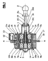
- the linear drive according to FIG. 1 has an actuating rod (1) whose head (2) can be coupled to an adjustable part, for example the reflector of a vehicle lighting.
- the head (2) opposite end of the control rod (1) is designed as a screw (3) and engages in a sleeve (4) which is provided in the middle with internal thread (5).
- the sleeve (4) serves as a hub of a rotor. It is rotatably supported by means of a ball bearing (6). On both sides of the ball bearing symmetrically to the same on the hub (4) two identical, permanent magnetic rings (7a and 7b) attached.
- the stator of the drive has two parts (8a and 8b) lying substantially symmetrically to the median plane (M) of the motor.
- the two stator parts are each provided with a coil (9a or 9b) which lie in a respective coil former (10a or 10b).
- the stator plates are closed on the outside and provided inside with unspecified, the rotor rings (7a and 7b) opposite stator teeth.
- shortened stator sections (11a and 11b) form a recess or a window in which a plug housing (12) is held.
- Connecting wires of the stator coils are connected to contact pins (13), which serve to connect a plug of a connecting cable.
- One of the contact pins serves as a ground contact pin and is connected to an extension of the stator lamination designed as a cutting clamp.
- Both stator parts are provided with fastening cams (14), which can serve to connect the drive to a suitable carrier.
- the two stator parts are provided with inwardly directed angles (15), which each with one radial and an axial mating surface the outer ring of the ball bearing (6) and thus ensure accurate mutual radial and axial centering between the rotor and stator.
- the bobbin (10a) is integrally provided with an approximately cylindrical extension (10c), at its outer end a guide (10d) for the control rod (1) is formed.
- the outer end of the extension (10c) also serves as an end stop for a plate (16) connected to the control rod (1) and the collar (2a) of the head 2.
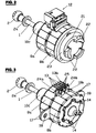
- FIG. 2 shows a variant of the drive.
- the structure corresponds largely to that of FIG. 1, and corresponding parts are the same as in Fig. 1.
- the control rod opposite end face of the bobbin is provided in this case with a cylindrical extension (21), formed on the mounting cam (22) are.
- the extension can also be attached to the cams (14) as a separate part.
- On the extension (21) a sealing ring (23) is placed.
- the drive can very easily in a correspondingly for the passage of the cam (22) provided with cutouts opening of a housing, such as a headlight housing, inserted and anchored bayonet-like, wherein the sealing ring (23) for a secure seal of the interior, in which are the active parts of the drive, provides. This results in a particularly advantageous use of the inventive drive according to claim 10.
- Fig. 3 corresponds largely to Fig. 2. It additionally shows the flanges 17 and each designed as a cutting terminal extension 24a and 24b of the stator 8a and 8b. Only with the insulation displacement terminal 24b, a contact pin 13b is connected, which serves the mass connection. The remaining contact pins 13 are connected to insulation displacement terminals 25, which are anchored in the bobbins 10a (in the back, not visible in FIG. 3) and 10b and connected to the winding terminals.
- the insulation displacement terminals 24 and 25 can also be used for direct connection to conductors of a connection cable.
Landscapes
- Engineering & Computer Science (AREA)
- Power Engineering (AREA)
- Connection Of Motors, Electrical Generators, Mechanical Devices, And The Like (AREA)
- Motor Or Generator Frames (AREA)
- Lighting Device Outwards From Vehicle And Optical Signal (AREA)
- Toys (AREA)
- Valve Device For Special Equipments (AREA)
- Surgical Instruments (AREA)
Description
- Die vorliegende Erfindung betrifft einen Linearantrieb, mit Stator und Rotor. Der Rotor derartiger Elektroantriebe ist im allgemeinen mittels mindestens zweier Lager beidseitig des Rotors gelagert (cf.
JP-A-01 077 442 - Es ist allerdings auch bekannt, nur einseitig des Rotors eine Lagerstelle anzubringen, aber das führt zu einer unstabilen Lagerung (cf.
EP-A-623 989 - Aus der
FR 2 555 835 - Aus der
US 4,398,109 ist ein Elektroantrieb mit einer verschiebbaren Gewindestange und einem einzigen Rotorlager bekannt, welches innerhalb der axialen Länge des Rotors angeordnet ist. Die Endanschläge für die Gewindestange sind an einem Rotorteil angeordnet und mit Stufen versehen, um ein Einschneiden der Gewindestange in das Rotorteil zu verhindern. Diese Ausgestaltung hat den Nachteil, dass die Herstellung des Elektroantriebs relativ teuer und aufwändig ist. - Ziel der Erfindung ist es, die genannten Hauptnachteile zu vermeiden, also eine kostengünstige, kompakte Bauweise zu ermöglichen. Die Lösung ist durch den Elektroantrieb gemäss Anspruch 1 gegeben. Ist ein Rotorlager axial innerhalb der axialen Länge des Rotors anbeordnet, ist nur eine Lagerstelle erforderlich und eventuelle Kippbewegungen des Rotors wirken sich bei einer gegebenen totalen Rotorlänge nur je entsprechend der Hälfte dieser Länge aus, so dass bei sonst gleichen Voraussetzungen mit einem geringeren Luftspalt und damit insgesamt geringeren Gesamtabmessungen gearbeitet werden kann. Weitere spezifische Konstruktionsmerkmale und deren Vorteile sind aus der folgenden Beschreibung und der Zeichnung ersichtlich, in welcher
- Fig. 1
- einen Axialschnitt durch einen elektrischen Linearantrieb, und
- Fig. 2 + 3
- räumliche Ansichten etwas anderer Ausführungen eines Linearantriebs
- Der Linearantrieb gemäss Fig. 1 weist eine Stellstange (1) auf, deren Kopf (2) mit einem einstellbaren Teil, beispielsweise dem Reflektor einer Fahrzeugbeleuchtung, gekuppelt sein kann. Das dem Kopf (2) gegenüberliegende Ende der Stellstange (1) ist als Schraube (3) ausgebildet und greift in eine Hülse (4), die in der Mitte mit Innengewinde (5) versehen ist. Die Hülse (4) dient als Nabe eines Rotors. Sie ist mittels eines Kugellagers (6) drehbar gelagert. Beidseits des Kugellagers sind symmetrisch zu demselben auf der Nabe (4) zwei gleichartige, permanentmagnetische Ringe (7a bzw. 7b) befestigt. Der Stator des Antriebs weist zwei im wesentlichen symmetrisch zur Mittelebene (M) des Motors liegende Teile (8a und 8b) auf. Die beiden Statorteile sind mit je einer Spule (9a bzw. 9b) versehen, die in je einem Spulenkörper (10a bzw. 10b) liegen. In der für Schrittmotoren üblichen Weise sind die Statorbleche aussen geschlossen und innen mit nicht näher bezeichneten, den Rotorringen (7a bzw. 7b) gegenüber liegenden Statorzähnen versehen. Wie in Fig. 1 oben dargestellt, bilden verkürzte Statorabschnitte (11a bzw. 11b) eine Ausnehmung bzw. ein Fenster, in welchem ein Steckergehäuse (12) gehalten ist. Anschlussdrähte der Statorspulen sind mit Kontaktstiften (13) verbunden, welche dem Anschluss eines Steckers eines Anschlusskabels dienen. Einer der Kontaktstifte dient als Masse-Kontaktstift und ist mit einem als Schneidklemme ausgebildeten Fortsatz des Statorbleches verbunden. Beide Statorteile sind mit Befestigungsnocken (14) versehen, welche zur Verbindung des Antriebs mit einem geeigneten Träger dienen können. Die beiden Statorteile sind mit nach innen gerichteten Winkeln (15) versehen, welche mit je einer radialen und einer axialen Passfläche den äusseren Ring des Kugellagers (6) umfasssen und damit eine genaue gegenseitige radiale und axiale Zentrierung zwischen Rotor und Stator gewährleisten. Wie in Fig. 1 unten ersichtlich, ist der Spulenkörper (10a) einteilig mit einem etwa zylindrischen Fortsatz (10c) versehen, an dessen äusserem Ende eine Führung (10d) für die Stellstange (1) gebildet ist. Das äussere Ende des Fortsatzes (10c) dient auch als Endanschlag für einen mit der Stellstange (1) verbundenen Teller (16) und den Bund (2a) des Kopfs 2.
- In Fig. 1 sind zwei Ergänzungsmöglichkeiten bzw. Varianten angedeutet. Die Statoreisen könnten, wie in Fig. 1 unten angedeutet, an diametral gegenüber liegenden Stellen mit nach aussen stehenden Flanschen (17) mit einem durchgehenden Loch (18) zur Montage des Antriebs versehen sein. Zur Drehsicherung der Stellstange (1) kann dieselbe beispielsweise mit einer Nut (19) versehen sein, in welche ein Nocken (20) des Fortsatzes (10c) des Spulenkörpers (10a) eingreift.
- Die sich aus der Gesamtkonzeption des Antriebs ergebenden Vorteile, soweit sie nicht bereits erwähnt wurden, können im wesentlichen wie folgt zusammengefasst werden:
- Bei gleicher Baugrösse des Motors wird das Statorpaket um die bisher durch die Lagerung genutzte Länge breiter.
- Das Lager wird axial und radial direkt durch die Haltstatoren befestigt.
- Sind Flansche (17, 18) vorgesehen, ist eine Befestigung des Antriebs ohne zusätzliche Teile möglich. Dabei kann der Schwerpunkt des Motors gegebenenfalls unter der Befestigungsstelle liegen, was im Falle von Schwingungen vorteilhaft ist. Da keine zusätzlichen Teile verwendet werden, ist die Kraftkette Befestigung - An-/Abtriebsschraube kurz und steif. Entsprechendes gilt bei Montage mittels der Befestigungsnocken (14), d.h., auch in diesem Falle sind keine besonderen Befestigungsorgane anzubringen.
- Wie erwähnt, dient auch das Statorblech zur direkten elektrischen Verbindung mit dem Masse-Kontakt-Stift.
- Fig.2 zeigt eine Ausführungsvariante des Antriebs. Der Aufbau entspricht weitgehend demjenigen nach Fig. 1, und entsprechende Teile sind gleich bezeichnet wie in Fig. 1. Die der Stellstange gegenüber liegende Stirnseite des Spulenkörpers ist in diesem Fall mit einem zylindrischen Fortsatz (21) versehen, an dem Montagenocken (22) angeformt sind. Der Fortsatz kann auch als separates Teil an die Nocken (14) angebaut werden. Auf den Fortsatz (21) ist ein Dichtungsring (23) aufgesetzt. Bei dieser Ausführung kann der Antrieb sehr einfach in eine entsprechend für den Durchtritt der Nocken (22) mit Ausschnitten versehene Öffnung eines Gehäuses, beispielsweise eines Scheinwerfergehäuses, eingeschoben und bajonettartig verankert werden, wobei der Dichtungsring (23) für eine sichere Abdichtung des Innenraums, in welchem sich die aktiven Teile des Antriebs befinden, sorgt. Es ergibt sich somit eine besonders vorteilhafte Verwendung des erfindungsgemässen Antriebs gemäss Anspruch 10.
- Fig. 3 entspricht weitgehend der Fig. 2. Sie zeigt zusätzlich die Flansche 17 und je einen als Schneidklemme ausgebildeten Fortsatz 24a bzw. 24b der Statorteile 8a und 8b. Nur mit der Schneidklemme 24b ist ein Kontaktstift 13b verbunden, welcher dem Massenanschluss dient. Die übrigen Kontaktstifte 13 sind mit Schneidklemmen 25 verbunden, welche in den Spulenkörpern 10a (in Fig. 3 hinten, nicht sichtbar) und 10b verankert und mit den Wicklungsanschlüssen verbunden sind. Die Schneidklemmen 24 und 25 können auch der direkten Verbindung mit Leitern eines Anschlusskabels dienen.
Claims (11)
- Elektroantrieb, welcher folgende Komponenten umfasst:einen Stator (8, 9, 10),einen Rotor (7a, 7b) mit einer Gewindehülse (4, 5),ein einziges Rotorlager (6), welches axial innerhalb der axialen Länge des Rotors angeordnet ist,eine axial verschiebbare Gewindestange (1), welche in die Gewindehülse (4, 5) greift und einen ersten Anschlag (16) und einen zweiten Anschlag (2a) umfasst, undeinen Fortsatz (10c) mit einem Ende (10d), durch welches die Gewindestange (1) hindurchgeführt ist, dadurch gekennzeichnet, daßdas Ende (10d) zwischen dem ersten (16) und zweiten Anschlag (2a) angeordnet ist und als Endanschlag für die beiden Anschläge (16, 2a) wirkt.
- Antrieb nach Anspruch 1, dadurch gekennzeichnet, dass die Gewindestange (1) mit einer Nut (19) versehen ist, in welche ein Nocken (20) des Fortsatzes (10c) eingreift.
- Antrieb nach Anspruch 1 oder 2, dadurch gekennzeichnet, dass das Lager (6) axial in der Rotormitte (M) angebracht ist.
- Antrieb nach einem der Ansprüche 1 - 3, dadurch gekennzeichnet, dass Stator (8, 9, 10) und Rotor (4, 5, 7) je zwei axial versetzte Teile (8a, 8b; 7a, 7b) aufweisen, wobei das Lager (6), bzw. der äussere Ring eines Kugellagers, zwischen den Statorteilen (8a, 8b) gehalten ist.
- Antrieb nach Anspruch 4, dadurch gekennzeichnet, dass das Lager (6) zwischen Passflächen von tiefgezogenen und/oder gebogenen Stator-Blechteilen (15) gehalten ist und dabei die Statorteile radial und axial zentriert.
- Antrieb nach einem der Ansprüche 1 - 5, dadurch gekennzeichnet, dass die Stator-Blechteile (8a, 8b) radiale Befestigungsflansche (17, 18) und Halter (11a, 11b) für eine Anschlussbuchse (12) zur Aufnahme des Steckers eines Anschlusskabels aufweist.
- Antrieb nach einem der Ansprüche 1 - 6, dadurch gekennzeichnet, dass Statorblechfortsätze (24a, 24b) als Schneidklemmen ausgebildet sind, von welchen mindestens einer (24b) mit einem Kontaktstift (13b) oder einem Anschlussleiter einen Massenanschluss bildet.
- Antrieb nach einem der Ansprüche 2 - 7, mit mindestens einem Spulenkörper (10a) aus Kunststoff, dadurch gekennzeichnet, dass der Spulenkörper als feststehender Teil einer Drehsicherung (19, 20) für die Gewindestange (1) dient.
- Antrieb nach einem der Ansprüche 1 - 8, gekennzeichnet durch einteilig mit dem Statorblech (8a, 8b) geformte Montageflansche (17, 18).
- Antrieb nach einem der Ansprüche 2 - 9, dadurch gekennzeichnet, dass er an mindestens einer seiner Stirnseiten mit Montageorganen, z.B. Nocken (22) zur Bajonettverbindung und Dichtungsmitteln, z.B. einem Dichtungsring (23) versehen ist.
- Antrieb nach einem der vorangehenden Ansprüche, dadurch gekennzeichnet, dass der erste Anschlag ein Teller (16) und/oder der zweite Anschlag ein Bund (2a) ist.
Priority Applications (5)
| Application Number | Priority Date | Filing Date | Title |
|---|---|---|---|
| DE50211425T DE50211425D1 (de) | 2002-05-17 | 2002-05-17 | Elektroantrieb |
| DE20221499U DE20221499U1 (de) | 2002-05-17 | 2002-05-17 | Elektroantrieb |
| AT02405402T ATE382202T1 (de) | 2002-05-17 | 2002-05-17 | Elektroantrieb |
| EP02405402A EP1363382B1 (de) | 2002-05-17 | 2002-05-17 | Elektroantrieb |
| US10/437,039 US6888277B2 (en) | 2002-05-17 | 2003-05-14 | Electro drive |
Applications Claiming Priority (1)
| Application Number | Priority Date | Filing Date | Title |
|---|---|---|---|
| EP02405402A EP1363382B1 (de) | 2002-05-17 | 2002-05-17 | Elektroantrieb |
Publications (2)
| Publication Number | Publication Date |
|---|---|
| EP1363382A1 EP1363382A1 (de) | 2003-11-19 |
| EP1363382B1 true EP1363382B1 (de) | 2007-12-26 |
Family
ID=29266038
Family Applications (1)
| Application Number | Title | Priority Date | Filing Date |
|---|---|---|---|
| EP02405402A Expired - Lifetime EP1363382B1 (de) | 2002-05-17 | 2002-05-17 | Elektroantrieb |
Country Status (4)
| Country | Link |
|---|---|
| US (1) | US6888277B2 (de) |
| EP (1) | EP1363382B1 (de) |
| AT (1) | ATE382202T1 (de) |
| DE (2) | DE50211425D1 (de) |
Families Citing this family (26)
| Publication number | Priority date | Publication date | Assignee | Title |
|---|---|---|---|---|
| JP2004153891A (ja) * | 2002-10-29 | 2004-05-27 | Mitsubishi Electric Corp | 回転電機 |
| DE102005054912B4 (de) * | 2005-11-17 | 2009-01-08 | Minebea Co., Ltd. | Linearstellantrieb |
| DE102005055868B4 (de) * | 2005-11-23 | 2008-06-12 | Minebea Co., Ltd. | Gewindetrieb für einen Linearstellmotor und Linearstellmotor |
| UA84707C2 (ru) * | 2006-01-30 | 2008-11-25 | Станислав Иванович Гусак | Электрическая машина для энергоустановки с потоком среды через трубу |
| DE102007016529A1 (de) * | 2007-04-05 | 2008-10-09 | Ejot Gmbh & Co. Kg | Axial verstellbare Stellstange mit Schraubengewinde und verdrehbarem Mutterstück |
| DE102007016652B4 (de) * | 2007-04-05 | 2013-05-23 | Hsian-Yi Huang | Auf- und abwärts bewegbarer Schrittmotor |
| US7513663B2 (en) * | 2007-04-25 | 2009-04-07 | Visteon Global Technologies, Inc. | Adaptive lighting system having dynamic recalibration |
| GB0713864D0 (en) * | 2007-07-17 | 2007-08-29 | Sheppard & Charnley Ltd | Electric motor/generator assembly |
| EP2051353B1 (de) * | 2007-10-15 | 2019-02-20 | Schaeffler Technologies AG & Co. KG | Antriebseinheit |
| DE102009000975A1 (de) | 2008-03-18 | 2009-09-24 | Saia-Burgess Murten Ag | Verfahren zur Herstellung einer Rotoraufhängung für einen Elektroantrieb und Rotoraufhängung |
| DE102008030016A1 (de) * | 2008-06-24 | 2009-12-31 | Schaeffler Kg | Linearstellantrieb, insbesondere zum Verstellen der Klappen in Kfz-Turboladern |
| KR101558563B1 (ko) | 2008-07-28 | 2015-10-08 | 엘지이노텍 주식회사 | 스텝 액츄에이터 |
| KR101567061B1 (ko) * | 2008-07-28 | 2015-11-09 | 엘지이노텍 주식회사 | 스텝 액츄에이터와 인쇄회로기판용 케이스의 결합 구조 |
| CH699672A1 (de) * | 2008-10-15 | 2010-04-15 | Saia Burgess Murten Ag | Aktuator mit einem Elektromotor und einem Gehäuseteil. |
| DE102008054330A1 (de) | 2008-11-03 | 2010-05-06 | Minebea Co., Ltd. | Zweiteiliges Motorgehäuse mit Bajonett-Verbindung |
| US8549804B2 (en) | 2010-10-21 | 2013-10-08 | Kimball International, Inc. | Office partition electrical system |
| DE102012019873A1 (de) | 2012-10-10 | 2013-05-02 | Daimler Ag | Elektrische Maschine und Verfahren zum Herstellen einer elektrischen Maschine |
| CN103795221A (zh) * | 2012-10-31 | 2014-05-14 | 上海鸣志电器股份有限公司 | 带防转螺杆的步进直线电机 |
| DE102012221992B4 (de) * | 2012-11-30 | 2023-06-15 | August Steinmeyer Gmbh & Co. Kg | Antriebseinrichtung, insbesondere Motor mit Kugel-Gewindetrieb |
| GB2508868A (en) | 2012-12-13 | 2014-06-18 | Johnson Electric Sa | Suspension system for the rotor of a linear actuator |
| DE102013015951A1 (de) * | 2013-09-25 | 2015-03-26 | Diehl Bgt Defence Gmbh & Co. Kg | Spindelaktuator |
| CN205081661U (zh) * | 2015-09-22 | 2016-03-09 | 大陆汽车电子(芜湖)有限公司 | 定子总成及包含该定子总成的步进驱动电机 |
| CN205544743U (zh) * | 2016-04-19 | 2016-08-31 | 合肥新沪屏蔽泵有限公司 | 泵组件 |
| CN115102357B (zh) * | 2022-07-25 | 2022-11-01 | 常州市丰源微特电机有限公司 | 一种微型直线步进电机、压装定向装置及其使用方法 |
| DE102023116040A1 (de) * | 2023-06-20 | 2024-12-24 | Schaeffler Technologies AG & Co. KG | Elektrische Maschine |
| CN118646236A (zh) * | 2024-05-28 | 2024-09-13 | 宁波精华电子科技股份有限公司 | 一种步进调光电机结构 |
Citations (2)
| Publication number | Priority date | Publication date | Assignee | Title |
|---|---|---|---|---|
| US4398109A (en) * | 1979-12-29 | 1983-08-09 | Kabushiki Kaisha Tokai Rika Denki Seisakusho | Electric motor |
| FR2555835A1 (fr) * | 1983-11-30 | 1985-05-31 | Portescap | Moteur electrique a rotor aimante en forme de disque |
Family Cites Families (23)
| Publication number | Priority date | Publication date | Assignee | Title |
|---|---|---|---|---|
| DE2458722A1 (de) * | 1974-12-12 | 1976-06-24 | Licentia Gmbh | Blechpaket einer elektrischen maschine |
| JPS6359746A (ja) * | 1986-08-29 | 1988-03-15 | Canon Inc | モ−タ |
| JPS63190265A (ja) * | 1987-01-30 | 1988-08-05 | キヤノン株式会社 | モ−タのリ−ド線接続構造 |
| JPH082161B2 (ja) | 1987-09-16 | 1996-01-10 | 博 寺町 | 複合サ−ボモ−タ |
| JPH083191Y2 (ja) * | 1989-02-17 | 1996-01-29 | 株式会社安川電機 | キャンドモータ |
| US5099161A (en) * | 1990-10-16 | 1992-03-24 | Savair Inc. | Compact electric linear actuator with tubular rotor |
| US5247216A (en) * | 1991-12-30 | 1993-09-21 | North American Philips Corporation | Stepper motor with integrated assembly |
| DE4206026A1 (de) * | 1992-02-27 | 1993-09-16 | Hella Kg Hueck & Co | Scheinwerfer fuer fahrzeuge |
| FR2691023A1 (fr) * | 1992-05-05 | 1993-11-12 | Rena France | Perfectionnement pour moteur électrique et pompe hydraulique équipée d'un tel moteur. |
| JPH06311686A (ja) * | 1993-04-20 | 1994-11-04 | Daikin Ind Ltd | 高速型モータ |
| EP0623989B1 (de) * | 1993-05-03 | 1997-03-05 | SAIA-Burgess Electronics AG | Linearantrieb |
| WO1996027936A1 (en) * | 1995-03-03 | 1996-09-12 | Tri-Tech, Inc. | Electric motor cup with monolithic mounting flange |
| US5811903A (en) * | 1995-09-26 | 1998-09-22 | Sankyo Seiki Mfg. Co., Ltd. | Motor |
| DE19547895A1 (de) * | 1995-12-21 | 1997-06-26 | Philips Patentverwaltung | Klauenpolschrittmotor mit einem Stator |
| JPH1094236A (ja) * | 1996-09-13 | 1998-04-10 | Sanyo Electric Co Ltd | 小形モータ |
| FR2770185B1 (fr) * | 1997-10-24 | 1999-12-03 | Valeo Vision | Projecteur comportant un correcteur d'orientation et correcteur d'orientation pour projecteur, notamment pour vehicule automobile |
| JP3592508B2 (ja) * | 1997-11-25 | 2004-11-24 | アスモ株式会社 | ステッピングモータ、光軸調整装置及び移動範囲設定方法 |
| CA2321585C (en) * | 1998-02-26 | 2007-09-04 | Tri-Tech, Inc. | Linear/rotary motor and method of use |
| JP2000014118A (ja) * | 1998-06-29 | 2000-01-14 | Minebea Co Ltd | ステッピングモータ |
| JP2000116082A (ja) * | 1998-09-30 | 2000-04-21 | Japan Servo Co Ltd | 外周駆動形電動機 |
| DE19858208B4 (de) * | 1998-12-17 | 2004-03-04 | Fhp Motors Gmbh | Schutzleiteranschluß an einem lamellierten Ständerblechpaket eines Elektromotors |
| FR2803451B1 (fr) * | 1999-12-30 | 2002-03-15 | Crouzet Automatismes | Moteur a rotor etanche avec roulement a billes |
| JP2001341577A (ja) * | 2000-05-31 | 2001-12-11 | Mitsubishi Electric Corp | 車両用前照灯システム、及び車両用前照灯の照射軸調整装置 |
-
2002
- 2002-05-17 EP EP02405402A patent/EP1363382B1/de not_active Expired - Lifetime
- 2002-05-17 DE DE50211425T patent/DE50211425D1/de not_active Expired - Lifetime
- 2002-05-17 DE DE20221499U patent/DE20221499U1/de not_active Expired - Lifetime
- 2002-05-17 AT AT02405402T patent/ATE382202T1/de not_active IP Right Cessation
-
2003
- 2003-05-14 US US10/437,039 patent/US6888277B2/en not_active Expired - Lifetime
Patent Citations (2)
| Publication number | Priority date | Publication date | Assignee | Title |
|---|---|---|---|---|
| US4398109A (en) * | 1979-12-29 | 1983-08-09 | Kabushiki Kaisha Tokai Rika Denki Seisakusho | Electric motor |
| FR2555835A1 (fr) * | 1983-11-30 | 1985-05-31 | Portescap | Moteur electrique a rotor aimante en forme de disque |
Also Published As
| Publication number | Publication date |
|---|---|
| US20030214191A1 (en) | 2003-11-20 |
| ATE382202T1 (de) | 2008-01-15 |
| EP1363382A1 (de) | 2003-11-19 |
| DE50211425D1 (de) | 2008-02-07 |
| US6888277B2 (en) | 2005-05-03 |
| DE20221499U1 (de) | 2006-02-23 |
Similar Documents
| Publication | Publication Date | Title |
|---|---|---|
| EP1363382B1 (de) | Elektroantrieb | |
| EP1689065B1 (de) | Stator eines Elektromotors und Verfahren zu seiner Herstellung | |
| DE69009346T2 (de) | Elektrische Motorpumpe mit Spaltrohr. | |
| DE102006021242B4 (de) | Elektromotor | |
| DE19705974A1 (de) | Elektromotor für eine Pumpe oder einen Lüfter | |
| DE102006019689B4 (de) | Motor und Bürstenhalter hierfür | |
| EP2182616A2 (de) | Bürstenloser Gleichstrommotor | |
| DE29516656U1 (de) | Kollektorloser Elektromotor | |
| DE102007044230A1 (de) | Drehmelder und bürstenfreier Motor | |
| WO2015048956A2 (de) | Positionierung eines umspritzten stators für einen kupplungsaktor oder einen getriebeaktor und einbringen eines rotorlagemagneten in einen solchen aktor | |
| DE102013113363A1 (de) | Stator für einen elektronisch kommutierten Gleichstrommotor | |
| EP0666424A1 (de) | Lüfter mit einem Lüfterrad | |
| EP1023759A1 (de) | Elektromotor, insbesondere mit einem lüfterrad zur bildung eines axial- oder radiallüfters | |
| DE102014218034A1 (de) | Positionierung eines umspritzten Stators für einen Kupplungsaktor oder einen Getriebeaktor und Einbringen eines Rotorlagemagneten in einen solchen Aktor | |
| DE102018106947A1 (de) | Elektromotor und Verfahren zum Montieren eines Elektromotors | |
| EP1882295B1 (de) | Elektrohydraulisches aggregat in verdichteter bauweise | |
| DE102008064131A1 (de) | Elektrische Maschine | |
| DE19748150B4 (de) | Spindelmotor mit Kontaktierung | |
| DE102007049209B4 (de) | Gleichstrommotor | |
| DE4309382A1 (de) | Elektronisch kommutierter Elektromotor | |
| DE102016124390A1 (de) | Motor vom Innenrotortyp | |
| EP1420503A1 (de) | Motorgehäuse | |
| EP3391509B1 (de) | Elektromotor | |
| WO2022233616A1 (de) | Antriebsvorrichtung mit einem bürstenlosen elektromotor | |
| EP0410488B1 (de) | Antriebseinheit mit einem Elektromotor |
Legal Events
| Date | Code | Title | Description |
|---|---|---|---|
| PUAI | Public reference made under article 153(3) epc to a published international application that has entered the european phase |
Free format text: ORIGINAL CODE: 0009012 |
|
| AK | Designated contracting states |
Kind code of ref document: A1 Designated state(s): AT BE CH CY DE DK ES FI FR GB GR IE IT LI LU MC NL PT SE TR |
|
| AX | Request for extension of the european patent |
Extension state: AL LT LV MK RO SI |
|
| 17P | Request for examination filed |
Effective date: 20040315 |
|
| AKX | Designation fees paid |
Designated state(s): AT BE CH CY DE DK ES FI FR GB GR IE IT LI LU MC NL PT SE TR |
|
| 17Q | First examination report despatched |
Effective date: 20050629 |
|
| GRAP | Despatch of communication of intention to grant a patent |
Free format text: ORIGINAL CODE: EPIDOSNIGR1 |
|
| GRAS | Grant fee paid |
Free format text: ORIGINAL CODE: EPIDOSNIGR3 |
|
| GRAA | (expected) grant |
Free format text: ORIGINAL CODE: 0009210 |
|
| RAP1 | Party data changed (applicant data changed or rights of an application transferred) |
Owner name: SAIA-BURGES MURTEN AG |
|
| AK | Designated contracting states |
Kind code of ref document: B1 Designated state(s): AT BE CH CY DE DK ES FI FR GB GR IE IT LI LU MC NL PT SE TR |
|
| REG | Reference to a national code |
Ref country code: GB Ref legal event code: FG4D Free format text: NOT ENGLISH |
|
| REG | Reference to a national code |
Ref country code: IE Ref legal event code: FG4D Free format text: LANGUAGE OF EP DOCUMENT: GERMAN |
|
| REG | Reference to a national code |
Ref country code: CH Ref legal event code: EP |
|
| REF | Corresponds to: |
Ref document number: 50211425 Country of ref document: DE Date of ref document: 20080207 Kind code of ref document: P |
|
| PG25 | Lapsed in a contracting state [announced via postgrant information from national office to epo] |
Ref country code: SE Free format text: LAPSE BECAUSE OF FAILURE TO SUBMIT A TRANSLATION OF THE DESCRIPTION OR TO PAY THE FEE WITHIN THE PRESCRIBED TIME-LIMIT Effective date: 20080326 |
|
| PG25 | Lapsed in a contracting state [announced via postgrant information from national office to epo] |
Ref country code: NL Free format text: LAPSE BECAUSE OF FAILURE TO SUBMIT A TRANSLATION OF THE DESCRIPTION OR TO PAY THE FEE WITHIN THE PRESCRIBED TIME-LIMIT Effective date: 20071226 Ref country code: FI Free format text: LAPSE BECAUSE OF FAILURE TO SUBMIT A TRANSLATION OF THE DESCRIPTION OR TO PAY THE FEE WITHIN THE PRESCRIBED TIME-LIMIT Effective date: 20071226 |
|
| NLV1 | Nl: lapsed or annulled due to failure to fulfill the requirements of art. 29p and 29m of the patents act | ||
| GBV | Gb: ep patent (uk) treated as always having been void in accordance with gb section 77(7)/1977 [no translation filed] | ||
| PG25 | Lapsed in a contracting state [announced via postgrant information from national office to epo] |
Ref country code: ES Free format text: LAPSE BECAUSE OF FAILURE TO SUBMIT A TRANSLATION OF THE DESCRIPTION OR TO PAY THE FEE WITHIN THE PRESCRIBED TIME-LIMIT Effective date: 20080406 |
|
| PG25 | Lapsed in a contracting state [announced via postgrant information from national office to epo] |
Ref country code: PT Free format text: LAPSE BECAUSE OF FAILURE TO SUBMIT A TRANSLATION OF THE DESCRIPTION OR TO PAY THE FEE WITHIN THE PRESCRIBED TIME-LIMIT Effective date: 20080526 |
|
| REG | Reference to a national code |
Ref country code: IE Ref legal event code: FD4D |
|
| EN | Fr: translation not filed | ||
| PG25 | Lapsed in a contracting state [announced via postgrant information from national office to epo] |
Ref country code: IE Free format text: LAPSE BECAUSE OF FAILURE TO SUBMIT A TRANSLATION OF THE DESCRIPTION OR TO PAY THE FEE WITHIN THE PRESCRIBED TIME-LIMIT Effective date: 20071226 Ref country code: DK Free format text: LAPSE BECAUSE OF FAILURE TO SUBMIT A TRANSLATION OF THE DESCRIPTION OR TO PAY THE FEE WITHIN THE PRESCRIBED TIME-LIMIT Effective date: 20071226 |
|
| PLBE | No opposition filed within time limit |
Free format text: ORIGINAL CODE: 0009261 |
|
| STAA | Information on the status of an ep patent application or granted ep patent |
Free format text: STATUS: NO OPPOSITION FILED WITHIN TIME LIMIT |
|
| BERE | Be: lapsed |
Owner name: SAIA-BURGES MURTEN A.G. Effective date: 20080531 |
|
| 26N | No opposition filed |
Effective date: 20080929 |
|
| PG25 | Lapsed in a contracting state [announced via postgrant information from national office to epo] |
Ref country code: GB Free format text: LAPSE BECAUSE OF FAILURE TO SUBMIT A TRANSLATION OF THE DESCRIPTION OR TO PAY THE FEE WITHIN THE PRESCRIBED TIME-LIMIT Effective date: 20071226 Ref country code: MC Free format text: LAPSE BECAUSE OF NON-PAYMENT OF DUE FEES Effective date: 20080531 |
|
| REG | Reference to a national code |
Ref country code: CH Ref legal event code: PL |
|
| PG25 | Lapsed in a contracting state [announced via postgrant information from national office to epo] |
Ref country code: GR Free format text: LAPSE BECAUSE OF FAILURE TO SUBMIT A TRANSLATION OF THE DESCRIPTION OR TO PAY THE FEE WITHIN THE PRESCRIBED TIME-LIMIT Effective date: 20080327 Ref country code: CH Free format text: LAPSE BECAUSE OF NON-PAYMENT OF DUE FEES Effective date: 20080531 Ref country code: LI Free format text: LAPSE BECAUSE OF NON-PAYMENT OF DUE FEES Effective date: 20080531 |
|
| PG25 | Lapsed in a contracting state [announced via postgrant information from national office to epo] |
Ref country code: BE Free format text: LAPSE BECAUSE OF NON-PAYMENT OF DUE FEES Effective date: 20080531 |
|
| PG25 | Lapsed in a contracting state [announced via postgrant information from national office to epo] |
Ref country code: FR Free format text: LAPSE BECAUSE OF FAILURE TO SUBMIT A TRANSLATION OF THE DESCRIPTION OR TO PAY THE FEE WITHIN THE PRESCRIBED TIME-LIMIT Effective date: 20081017 |
|
| PG25 | Lapsed in a contracting state [announced via postgrant information from national office to epo] |
Ref country code: CY Free format text: LAPSE BECAUSE OF FAILURE TO SUBMIT A TRANSLATION OF THE DESCRIPTION OR TO PAY THE FEE WITHIN THE PRESCRIBED TIME-LIMIT Effective date: 20071226 |
|
| PG25 | Lapsed in a contracting state [announced via postgrant information from national office to epo] |
Ref country code: AT Free format text: LAPSE BECAUSE OF NON-PAYMENT OF DUE FEES Effective date: 20080517 |
|
| PG25 | Lapsed in a contracting state [announced via postgrant information from national office to epo] |
Ref country code: LU Free format text: LAPSE BECAUSE OF NON-PAYMENT OF DUE FEES Effective date: 20080517 |
|
| PG25 | Lapsed in a contracting state [announced via postgrant information from national office to epo] |
Ref country code: TR Free format text: LAPSE BECAUSE OF FAILURE TO SUBMIT A TRANSLATION OF THE DESCRIPTION OR TO PAY THE FEE WITHIN THE PRESCRIBED TIME-LIMIT Effective date: 20071226 |
|
| PG25 | Lapsed in a contracting state [announced via postgrant information from national office to epo] |
Ref country code: IT Free format text: LAPSE BECAUSE OF NON-PAYMENT OF DUE FEES Effective date: 20080531 |
|
| REG | Reference to a national code |
Ref country code: DE Ref legal event code: R082 Ref document number: 50211425 Country of ref document: DE Representative=s name: PUSCHMANN BORCHERT BARDEHLE PATENTANWAELTE PAR, DE |
|
| REG | Reference to a national code |
Ref country code: DE Ref legal event code: R081 Ref document number: 50211425 Country of ref document: DE Owner name: JOHNSON ELECTRIC SWITZERLAND AG, CH Free format text: FORMER OWNER: SAIA-BURGESS MURTEN AG, MURTEN, CH Effective date: 20111012 Ref country code: DE Ref legal event code: R082 Ref document number: 50211425 Country of ref document: DE Representative=s name: PUSCHMANN BORCHERT BARDEHLE PATENTANWAELTE PAR, DE Effective date: 20111012 |
|
| REG | Reference to a national code |
Ref country code: DE Ref legal event code: R082 Ref document number: 50211425 Country of ref document: DE Representative=s name: PUSCHMANN BORCHERT BARDEHLE PATENTANWAELTE PAR, DE Ref country code: DE Ref legal event code: R081 Ref document number: 50211425 Country of ref document: DE Owner name: JOHNSON ELECTRIC INTERNATIONAL AG, CH Free format text: FORMER OWNER: JOHNSON ELECTRIC SWITZERLAND AG, MURTEN, CH Ref country code: DE Ref legal event code: R082 Ref document number: 50211425 Country of ref document: DE Representative=s name: PUSCHMANN BORCHERT KAISER KLETTNER PATENTANWAE, DE |
|
| PGFP | Annual fee paid to national office [announced via postgrant information from national office to epo] |
Ref country code: DE Payment date: 20210420 Year of fee payment: 20 |
|
| REG | Reference to a national code |
Ref country code: DE Ref legal event code: R071 Ref document number: 50211425 Country of ref document: DE |