EP1363382B1 - Electric drive - Google Patents
Electric drive Download PDFInfo
- Publication number
- EP1363382B1 EP1363382B1 EP02405402A EP02405402A EP1363382B1 EP 1363382 B1 EP1363382 B1 EP 1363382B1 EP 02405402 A EP02405402 A EP 02405402A EP 02405402 A EP02405402 A EP 02405402A EP 1363382 B1 EP1363382 B1 EP 1363382B1
- Authority
- EP
- European Patent Office
- Prior art keywords
- drive according
- stator
- rotor
- stop
- bearing
- Prior art date
- Legal status (The legal status is an assumption and is not a legal conclusion. Google has not performed a legal analysis and makes no representation as to the accuracy of the status listed.)
- Expired - Lifetime
Links
Images
Classifications
-
- H—ELECTRICITY
- H02—GENERATION; CONVERSION OR DISTRIBUTION OF ELECTRIC POWER
- H02K—DYNAMO-ELECTRIC MACHINES
- H02K5/00—Casings; Enclosures; Supports
- H02K5/04—Casings or enclosures characterised by the shape, form or construction thereof
- H02K5/22—Auxiliary parts of casings not covered by groups H02K5/06-H02K5/20, e.g. shaped to form connection boxes or terminal boxes
- H02K5/225—Terminal boxes or connection arrangements
-
- H—ELECTRICITY
- H02—GENERATION; CONVERSION OR DISTRIBUTION OF ELECTRIC POWER
- H02K—DYNAMO-ELECTRIC MACHINES
- H02K3/00—Details of windings
- H02K3/46—Fastening of windings on the stator or rotor structure
- H02K3/52—Fastening salient pole windings or connections thereto
- H02K3/521—Fastening salient pole windings or connections thereto applicable to stators only
- H02K3/525—Annular coils, e.g. for cores of the claw-pole type
-
- H—ELECTRICITY
- H02—GENERATION; CONVERSION OR DISTRIBUTION OF ELECTRIC POWER
- H02K—DYNAMO-ELECTRIC MACHINES
- H02K5/00—Casings; Enclosures; Supports
-
- H—ELECTRICITY
- H02—GENERATION; CONVERSION OR DISTRIBUTION OF ELECTRIC POWER
- H02K—DYNAMO-ELECTRIC MACHINES
- H02K5/00—Casings; Enclosures; Supports
- H02K5/04—Casings or enclosures characterised by the shape, form or construction thereof
- H02K5/16—Means for supporting bearings, e.g. insulating supports or means for fitting bearings in the bearing-shields
- H02K5/173—Means for supporting bearings, e.g. insulating supports or means for fitting bearings in the bearing-shields using bearings with rolling contact, e.g. ball bearings
-
- H—ELECTRICITY
- H02—GENERATION; CONVERSION OR DISTRIBUTION OF ELECTRIC POWER
- H02K—DYNAMO-ELECTRIC MACHINES
- H02K7/00—Arrangements for handling mechanical energy structurally associated with dynamo-electric machines, e.g. structural association with mechanical driving motors or auxiliary dynamo-electric machines
- H02K7/06—Means for converting reciprocating motion into rotary motion or vice versa
-
- H—ELECTRICITY
- H02—GENERATION; CONVERSION OR DISTRIBUTION OF ELECTRIC POWER
- H02K—DYNAMO-ELECTRIC MACHINES
- H02K7/00—Arrangements for handling mechanical energy structurally associated with dynamo-electric machines, e.g. structural association with mechanical driving motors or auxiliary dynamo-electric machines
- H02K7/08—Structural association with bearings
- H02K7/081—Structural association with bearings specially adapted for worm gear drives
-
- H—ELECTRICITY
- H02—GENERATION; CONVERSION OR DISTRIBUTION OF ELECTRIC POWER
- H02K—DYNAMO-ELECTRIC MACHINES
- H02K2201/00—Specific aspects not provided for in the other groups of this subclass relating to the magnetic circuits
- H02K2201/12—Transversal flux machines
-
- H—ELECTRICITY
- H02—GENERATION; CONVERSION OR DISTRIBUTION OF ELECTRIC POWER
- H02K—DYNAMO-ELECTRIC MACHINES
- H02K37/00—Motors with rotor rotating step by step and without interrupter or commutator driven by the rotor, e.g. stepping motors
- H02K37/10—Motors with rotor rotating step by step and without interrupter or commutator driven by the rotor, e.g. stepping motors of permanent magnet type
- H02K37/12—Motors with rotor rotating step by step and without interrupter or commutator driven by the rotor, e.g. stepping motors of permanent magnet type with stationary armatures and rotating magnets
- H02K37/14—Motors with rotor rotating step by step and without interrupter or commutator driven by the rotor, e.g. stepping motors of permanent magnet type with stationary armatures and rotating magnets with magnets rotating within the armatures
Abstract
Description
Die vorliegende Erfindung betrifft einen Linearantrieb, mit Stator und Rotor. Der Rotor derartiger Elektroantriebe ist im allgemeinen mittels mindestens zweier Lager beidseitig des Rotors gelagert (cf.
Es ist allerdings auch bekannt, nur einseitig des Rotors eine Lagerstelle anzubringen, aber das führt zu einer unstabilen Lagerung (cf.
Aus der
Aus der
Ziel der Erfindung ist es, die genannten Hauptnachteile zu vermeiden, also eine kostengünstige, kompakte Bauweise zu ermöglichen. Die Lösung ist durch den Elektroantrieb gemäss Anspruch 1 gegeben. Ist ein Rotorlager axial innerhalb der axialen Länge des Rotors anbeordnet, ist nur eine Lagerstelle erforderlich und eventuelle Kippbewegungen des Rotors wirken sich bei einer gegebenen totalen Rotorlänge nur je entsprechend der Hälfte dieser Länge aus, so dass bei sonst gleichen Voraussetzungen mit einem geringeren Luftspalt und damit insgesamt geringeren Gesamtabmessungen gearbeitet werden kann. Weitere spezifische Konstruktionsmerkmale und deren Vorteile sind aus der folgenden Beschreibung und der Zeichnung ersichtlich, in welcher
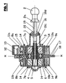
- Fig. 1
- einen Axialschnitt durch einen elektrischen Linearantrieb, und
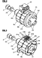
- Fig. 2 + 3
- räumliche Ansichten etwas anderer Ausführungen eines Linearantriebs
- Fig. 1
- an axial section through an electric linear drive, and
- Fig. 2 + 3
- Spatial views of something different versions of a linear actuator
Der Linearantrieb gemäss Fig. 1 weist eine Stellstange (1) auf, deren Kopf (2) mit einem einstellbaren Teil, beispielsweise dem Reflektor einer Fahrzeugbeleuchtung, gekuppelt sein kann. Das dem Kopf (2) gegenüberliegende Ende der Stellstange (1) ist als Schraube (3) ausgebildet und greift in eine Hülse (4), die in der Mitte mit Innengewinde (5) versehen ist. Die Hülse (4) dient als Nabe eines Rotors. Sie ist mittels eines Kugellagers (6) drehbar gelagert. Beidseits des Kugellagers sind symmetrisch zu demselben auf der Nabe (4) zwei gleichartige, permanentmagnetische Ringe (7a bzw. 7b) befestigt. Der Stator des Antriebs weist zwei im wesentlichen symmetrisch zur Mittelebene (M) des Motors liegende Teile (8a und 8b) auf. Die beiden Statorteile sind mit je einer Spule (9a bzw. 9b) versehen, die in je einem Spulenkörper (10a bzw. 10b) liegen. In der für Schrittmotoren üblichen Weise sind die Statorbleche aussen geschlossen und innen mit nicht näher bezeichneten, den Rotorringen (7a bzw. 7b) gegenüber liegenden Statorzähnen versehen. Wie in Fig. 1 oben dargestellt, bilden verkürzte Statorabschnitte (11a bzw. 11b) eine Ausnehmung bzw. ein Fenster, in welchem ein Steckergehäuse (12) gehalten ist. Anschlussdrähte der Statorspulen sind mit Kontaktstiften (13) verbunden, welche dem Anschluss eines Steckers eines Anschlusskabels dienen. Einer der Kontaktstifte dient als Masse-Kontaktstift und ist mit einem als Schneidklemme ausgebildeten Fortsatz des Statorbleches verbunden. Beide Statorteile sind mit Befestigungsnocken (14) versehen, welche zur Verbindung des Antriebs mit einem geeigneten Träger dienen können. Die beiden Statorteile sind mit nach innen gerichteten Winkeln (15) versehen, welche mit je einer radialen und einer axialen Passfläche den äusseren Ring des Kugellagers (6) umfasssen und damit eine genaue gegenseitige radiale und axiale Zentrierung zwischen Rotor und Stator gewährleisten. Wie in Fig. 1 unten ersichtlich, ist der Spulenkörper (10a) einteilig mit einem etwa zylindrischen Fortsatz (10c) versehen, an dessen äusserem Ende eine Führung (10d) für die Stellstange (1) gebildet ist. Das äussere Ende des Fortsatzes (10c) dient auch als Endanschlag für einen mit der Stellstange (1) verbundenen Teller (16) und den Bund (2a) des Kopfs 2.The linear drive according to FIG. 1 has an actuating rod (1) whose head (2) can be coupled to an adjustable part, for example the reflector of a vehicle lighting. The head (2) opposite end of the control rod (1) is designed as a screw (3) and engages in a sleeve (4) which is provided in the middle with internal thread (5). The sleeve (4) serves as a hub of a rotor. It is rotatably supported by means of a ball bearing (6). On both sides of the ball bearing symmetrically to the same on the hub (4) two identical, permanent magnetic rings (7a and 7b) attached. The stator of the drive has two parts (8a and 8b) lying substantially symmetrically to the median plane (M) of the motor. The two stator parts are each provided with a coil (9a or 9b) which lie in a respective coil former (10a or 10b). In the usual way for stepper motors, the stator plates are closed on the outside and provided inside with unspecified, the rotor rings (7a and 7b) opposite stator teeth. As shown in Fig. 1 above, shortened stator sections (11a and 11b) form a recess or a window in which a plug housing (12) is held. Connecting wires of the stator coils are connected to contact pins (13), which serve to connect a plug of a connecting cable. One of the contact pins serves as a ground contact pin and is connected to an extension of the stator lamination designed as a cutting clamp. Both stator parts are provided with fastening cams (14), which can serve to connect the drive to a suitable carrier. The two stator parts are provided with inwardly directed angles (15), which each with one radial and an axial mating surface the outer ring of the ball bearing (6) and thus ensure accurate mutual radial and axial centering between the rotor and stator. As seen in Fig. 1 below, the bobbin (10a) is integrally provided with an approximately cylindrical extension (10c), at its outer end a guide (10d) for the control rod (1) is formed. The outer end of the extension (10c) also serves as an end stop for a plate (16) connected to the control rod (1) and the collar (2a) of the
In Fig. 1 sind zwei Ergänzungsmöglichkeiten bzw. Varianten angedeutet. Die Statoreisen könnten, wie in Fig. 1 unten angedeutet, an diametral gegenüber liegenden Stellen mit nach aussen stehenden Flanschen (17) mit einem durchgehenden Loch (18) zur Montage des Antriebs versehen sein. Zur Drehsicherung der Stellstange (1) kann dieselbe beispielsweise mit einer Nut (19) versehen sein, in welche ein Nocken (20) des Fortsatzes (10c) des Spulenkörpers (10a) eingreift.
- Die sich aus der Gesamtkonzeption des Antriebs ergebenden Vorteile, soweit sie nicht bereits erwähnt wurden, können im wesentlichen wie folgt zusammengefasst werden:
- Bei gleicher Baugrösse des Motors wird das Statorpaket um die bisher durch die Lagerung genutzte Länge breiter.
- Das Lager wird axial und radial direkt durch die Haltstatoren befestigt.
- Sind Flansche (17, 18) vorgesehen, ist eine Befestigung des Antriebs ohne zusätzliche Teile möglich. Dabei kann der Schwerpunkt des Motors gegebenenfalls unter der Befestigungsstelle liegen, was im Falle von Schwingungen vorteilhaft ist. Da keine zusätzlichen Teile verwendet werden, ist die Kraftkette Befestigung - An-/Abtriebsschraube kurz und steif. Entsprechendes gilt bei Montage mittels der Befestigungsnocken (14), d.h., auch in diesem Falle sind keine besonderen Befestigungsorgane anzubringen.
- Wie erwähnt, dient auch das Statorblech zur direkten elektrischen Verbindung mit dem Masse-Kontakt-Stift.
- The advantages resulting from the overall design of the drive, if not already mentioned, can essentially be summarized as follows:
- With the same size of the motor, the stator is wider by the previously used by the storage length.
- The bearing is fixed axially and radially directly by the holding stators.
- Flanges (17, 18) are provided, a mounting of the drive is possible without additional parts. The center of gravity of the engine may be below the attachment point, which is advantageous in the case of vibrations. Since no additional parts are used, the force chain attachment - driving / driving screw is short and stiff. The same applies when mounting by means of the attachment cams (14), ie, in this case, too, no special attachment devices are to be attached.
- As mentioned, the stator plate also serves for direct electrical connection to the ground contact pin.
Fig.2 zeigt eine Ausführungsvariante des Antriebs. Der Aufbau entspricht weitgehend demjenigen nach Fig. 1, und entsprechende Teile sind gleich bezeichnet wie in Fig. 1. Die der Stellstange gegenüber liegende Stirnseite des Spulenkörpers ist in diesem Fall mit einem zylindrischen Fortsatz (21) versehen, an dem Montagenocken (22) angeformt sind. Der Fortsatz kann auch als separates Teil an die Nocken (14) angebaut werden. Auf den Fortsatz (21) ist ein Dichtungsring (23) aufgesetzt. Bei dieser Ausführung kann der Antrieb sehr einfach in eine entsprechend für den Durchtritt der Nocken (22) mit Ausschnitten versehene Öffnung eines Gehäuses, beispielsweise eines Scheinwerfergehäuses, eingeschoben und bajonettartig verankert werden, wobei der Dichtungsring (23) für eine sichere Abdichtung des Innenraums, in welchem sich die aktiven Teile des Antriebs befinden, sorgt. Es ergibt sich somit eine besonders vorteilhafte Verwendung des erfindungsgemässen Antriebs gemäss Anspruch 10.2 shows a variant of the drive. The structure corresponds largely to that of FIG. 1, and corresponding parts are the same as in Fig. 1. The control rod opposite end face of the bobbin is provided in this case with a cylindrical extension (21), formed on the mounting cam (22) are. The extension can also be attached to the cams (14) as a separate part. On the extension (21) a sealing ring (23) is placed. In this embodiment, the drive can very easily in a correspondingly for the passage of the cam (22) provided with cutouts opening of a housing, such as a headlight housing, inserted and anchored bayonet-like, wherein the sealing ring (23) for a secure seal of the interior, in which are the active parts of the drive, provides. This results in a particularly advantageous use of the inventive drive according to claim 10.
Fig. 3 entspricht weitgehend der Fig. 2. Sie zeigt zusätzlich die Flansche 17 und je einen als Schneidklemme ausgebildeten Fortsatz 24a bzw. 24b der Statorteile 8a und 8b. Nur mit der Schneidklemme 24b ist ein Kontaktstift 13b verbunden, welcher dem Massenanschluss dient. Die übrigen Kontaktstifte 13 sind mit Schneidklemmen 25 verbunden, welche in den Spulenkörpern 10a (in Fig. 3 hinten, nicht sichtbar) und 10b verankert und mit den Wicklungsanschlüssen verbunden sind. Die Schneidklemmen 24 und 25 können auch der direkten Verbindung mit Leitern eines Anschlusskabels dienen.Fig. 3 corresponds largely to Fig. 2. It additionally shows the
Claims (11)
- Electro drive, comprising the following components:a stator (8, 9, 10),a rotor (7a, 7b) having a threaded sleeve (4, 5),a single rotor bearing (6) that is axially arranged within the axial length of the rotor,an axially displaceable threaded rod (1) that engages in the threaded sleeve (4, 5) and comprises a first stop (16) and a second stop (2a), anda prolongation (10c) having an end (10d) through which the threaded rod (1) is guided,characterised in that
the end (10d) is located between the first (16) and the second stop (2a) and serves as an end stop for the two stops (16, 2a). - Drive according to claim 1, characterised in that the threaded rod (1) is provided with a groove (19) in which a cam (20) of the prolongation (10c) engages.
- Drive according to claim 1 or 2, characterised in that the bearing (6) is arranged axially in the centre (M) of the rotor.
- Drive according to one of claims 1 to 3, characterised in that the stator (8, 9, 10) and the rotor (4, 5, 7) each comprise two axially offset portions (8a, 8b; 7a, 7b), the bearing (6), or the outer race of a ball bearing, being held between the stator portions (8a, 8b).
- Drive according to claim 4, characterised in that the bearing (6) is held between fitting surfaces of deep-drawn and/or bent stator plate portions (15), thereby centring the stator portions radially and axially.
- Drive according to one of claims 1 to 5, characterised in that the stator plate portions (8a, 8b) comprise radial mounting flanges (17, 18) and holders (11a, 11b) for a connector socket (12) for receiving the plug of a connecting cable.
- Drive according to one of claims 1 to 6, characterised in that stator plate projections (24a, 24b) are designed as insulation displacement contacts of which at least one (24b) forms a ground connection with a contact pin (13b) or a connecting lead.
- Drive according to one of claims 2 to 7, comprising at least one bobbin (10a) of synthetic material, characterised in that the bobbin serves as a stationary part of a rotational lock (19, 20) for the threaded rod (1).
- Drive according to one of claims 1 to 8, characterised by mounting flanges (17, 18) that are integrally formed with the stator plate (8a, 8b).
- Drive according to one of claims 2 to 9, characterised in that it is provided on at least one of its face sides with mounting members, e.g. cams (22) for a bayonet attachment, and with sealing means, e.g. a sealing ring (23).
- Drive according to one of the preceding claims, characterised in that the first stop is a disk (16) and/or the second stop is a collar (2a).
Priority Applications (5)
| Application Number | Priority Date | Filing Date | Title |
|---|---|---|---|
| DE50211425T DE50211425D1 (en) | 2002-05-17 | 2002-05-17 | electric drive |
| DE20221499U DE20221499U1 (en) | 2002-05-17 | 2002-05-17 | Linear actuator integrating electric motor with spindle drive for e.g. adjusting headlamp, has single rotor bearing located within axial length of rotor. |
| EP02405402A EP1363382B1 (en) | 2002-05-17 | 2002-05-17 | Electric drive |
| AT02405402T ATE382202T1 (en) | 2002-05-17 | 2002-05-17 | ELECTRIC DRIVE |
| US10/437,039 US6888277B2 (en) | 2002-05-17 | 2003-05-14 | Electro drive |
Applications Claiming Priority (1)
| Application Number | Priority Date | Filing Date | Title |
|---|---|---|---|
| EP02405402A EP1363382B1 (en) | 2002-05-17 | 2002-05-17 | Electric drive |
Publications (2)
| Publication Number | Publication Date |
|---|---|
| EP1363382A1 EP1363382A1 (en) | 2003-11-19 |
| EP1363382B1 true EP1363382B1 (en) | 2007-12-26 |
Family
ID=29266038
Family Applications (1)
| Application Number | Title | Priority Date | Filing Date |
|---|---|---|---|
| EP02405402A Expired - Lifetime EP1363382B1 (en) | 2002-05-17 | 2002-05-17 | Electric drive |
Country Status (4)
| Country | Link |
|---|---|
| US (1) | US6888277B2 (en) |
| EP (1) | EP1363382B1 (en) |
| AT (1) | ATE382202T1 (en) |
| DE (2) | DE20221499U1 (en) |
Families Citing this family (24)
| Publication number | Priority date | Publication date | Assignee | Title |
|---|---|---|---|---|
| JP2004153891A (en) * | 2002-10-29 | 2004-05-27 | Mitsubishi Electric Corp | Rotary electric machine |
| DE102005054912B4 (en) * | 2005-11-17 | 2009-01-08 | Minebea Co., Ltd. | Linear Actuator |
| DE102005055868B4 (en) * | 2005-11-23 | 2008-06-12 | Minebea Co., Ltd. | Screw drive for a linear actuator and linear actuator |
| UA84707C2 (en) * | 2006-01-30 | 2008-11-25 | Станислав Иванович Гусак | Electric machine for power unit with medium flow through pipe |
| DE102007016529A1 (en) * | 2007-04-05 | 2008-10-09 | Ejot Gmbh & Co. Kg | Axially adjustable control rod with screw thread and turnable nut piece |
| DE102007016652B4 (en) * | 2007-04-05 | 2013-05-23 | Hsian-Yi Huang | Up and down stepper motor |
| US7513663B2 (en) * | 2007-04-25 | 2009-04-07 | Visteon Global Technologies, Inc. | Adaptive lighting system having dynamic recalibration |
| GB0713864D0 (en) | 2007-07-17 | 2007-08-29 | Sheppard & Charnley Ltd | Electric motor/generator assembly |
| EP2051353B1 (en) * | 2007-10-15 | 2019-02-20 | Schaeffler Technologies AG & Co. KG | Drive unit |
| DE102009000975A1 (en) | 2008-03-18 | 2009-09-24 | Saia-Burgess Murten Ag | Rotor suspension manufacturing method for electric drive i.e. linear drive, involves inserting rotor bearing into casing and fixing rotor bearing by deforming of casing, where casing is provided with flange at fixation unit |
| DE102008030016A1 (en) | 2008-06-24 | 2009-12-31 | Schaeffler Kg | Linear actuator, in particular for adjusting the flaps in motor vehicle turbochargers |
| KR101558563B1 (en) * | 2008-07-28 | 2015-10-08 | 엘지이노텍 주식회사 | Step Actuator |
| KR101567061B1 (en) * | 2008-07-28 | 2015-11-09 | 엘지이노텍 주식회사 | Connecting structure between step actuator and cases of printed circuit board |
| CH699672A1 (en) * | 2008-10-15 | 2010-04-15 | Saia Burgess Murten Ag | Actuator for use in e.g. heating-ventilation-air conditioning system of motor vehicle, has coils arranged at coil body, and housing part formed as support for transmission, where housing part is formed as single piece with coil body |
| DE102008054330A1 (en) | 2008-11-03 | 2010-05-06 | Minebea Co., Ltd. | Claw pole motor i.e. linear stepping motor, has housing part connected with stator part of stator, where stator part comprises coil element that is arranged in axial direction partly outside housing part |
| US8549804B2 (en) | 2010-10-21 | 2013-10-08 | Kimball International, Inc. | Office partition electrical system |
| DE102012019873A1 (en) | 2012-10-10 | 2013-05-02 | Daimler Ag | Electrical machine e.g. permanent magnet synchronous machine, has a bearing arrangement having two bearings rotatably mounted on a stator and arranged in axial direction within the axial extent of the stator and/or the rotor |
| CN103795221A (en) * | 2012-10-31 | 2014-05-14 | 上海鸣志电器股份有限公司 | Stepping linear motor equipped with rotation-proof screw rod |
| DE102012221992B4 (en) * | 2012-11-30 | 2023-06-15 | August Steinmeyer Gmbh & Co. Kg | Drive device, in particular motor with ball screw drive |
| GB2508868A (en) | 2012-12-13 | 2014-06-18 | Johnson Electric Sa | Suspension system for the rotor of a linear actuator |
| DE102013015951A1 (en) * | 2013-09-25 | 2015-03-26 | Diehl Bgt Defence Gmbh & Co. Kg | spindle actuator |
| CN205081661U (en) * | 2015-09-22 | 2016-03-09 | 大陆汽车电子(芜湖)有限公司 | Stator assembly and contain step drive motor of this stator assembly |
| CN205544743U (en) * | 2016-04-19 | 2016-08-31 | 合肥新沪屏蔽泵有限公司 | Pump assembly |
| CN115102357B (en) * | 2022-07-25 | 2022-11-01 | 常州市丰源微特电机有限公司 | Miniature linear stepping motor, press-fitting orientation device and use method thereof |
Citations (2)
| Publication number | Priority date | Publication date | Assignee | Title |
|---|---|---|---|---|
| US4398109A (en) * | 1979-12-29 | 1983-08-09 | Kabushiki Kaisha Tokai Rika Denki Seisakusho | Electric motor |
| FR2555835A1 (en) * | 1983-11-30 | 1985-05-31 | Portescap | ELECTRIC MOTOR WITH DISC-LIKE MAGNET ROTOR |
Family Cites Families (23)
| Publication number | Priority date | Publication date | Assignee | Title |
|---|---|---|---|---|
| DE2458722A1 (en) * | 1974-12-12 | 1976-06-24 | Licentia Gmbh | Laminated core for electric machine - has earthing plugs set into outer circumference and formed by pairs of parallel radial slots |
| JPS6359746A (en) * | 1986-08-29 | 1988-03-15 | Canon Inc | Motor |
| JPS63190265A (en) * | 1987-01-30 | 1988-08-05 | キヤノン株式会社 | Construction of motor lead joint |
| JPH082161B2 (en) | 1987-09-16 | 1996-01-10 | 博 寺町 | Combined servo motor |
| JPH083191Y2 (en) * | 1989-02-17 | 1996-01-29 | 株式会社安川電機 | Canned motor |
| US5099161A (en) * | 1990-10-16 | 1992-03-24 | Savair Inc. | Compact electric linear actuator with tubular rotor |
| US5247216A (en) * | 1991-12-30 | 1993-09-21 | North American Philips Corporation | Stepper motor with integrated assembly |
| DE4206026A1 (en) * | 1992-02-27 | 1993-09-16 | Hella Kg Hueck & Co | HEADLIGHTS FOR VEHICLES |
| FR2691023A1 (en) * | 1992-05-05 | 1993-11-12 | Rena France | Improvement for electric motor and hydraulic pump equipped with such a motor. |
| JPH06311686A (en) * | 1993-04-20 | 1994-11-04 | Daikin Ind Ltd | High-speed motor |
| DE69401840T2 (en) * | 1993-05-03 | 1997-06-12 | Saia Burgess Electronics Ag | linear actuator |
| WO1996027936A1 (en) * | 1995-03-03 | 1996-09-12 | Tri-Tech, Inc. | Electric motor cup with monolithic mounting flange |
| US5811903A (en) * | 1995-09-26 | 1998-09-22 | Sankyo Seiki Mfg. Co., Ltd. | Motor |
| DE19547895A1 (en) * | 1995-12-21 | 1997-06-26 | Philips Patentverwaltung | Claw pole stepper motor with a stator |
| JPH1094236A (en) * | 1996-09-13 | 1998-04-10 | Sanyo Electric Co Ltd | Small-sized motor |
| FR2770185B1 (en) * | 1997-10-24 | 1999-12-03 | Valeo Vision | PROJECTOR COMPRISING AN ORIENTATION CORRECTOR AND ORIENTATION CORRECTOR FOR A PROJECTOR, PARTICULARLY FOR A MOTOR VEHICLE |
| JP3592508B2 (en) * | 1997-11-25 | 2004-11-24 | アスモ株式会社 | Stepping motor, optical axis adjusting device, and moving range setting method |
| CA2321585C (en) * | 1998-02-26 | 2007-09-04 | Tri-Tech, Inc. | Linear/rotary motor and method of use |
| JP2000014118A (en) * | 1998-06-29 | 2000-01-14 | Minebea Co Ltd | Stepping motor |
| JP2000116082A (en) * | 1998-09-30 | 2000-04-21 | Japan Servo Co Ltd | Outer periphery drive electric motor |
| DE19858208B4 (en) * | 1998-12-17 | 2004-03-04 | Fhp Motors Gmbh | Protective conductor connection on a laminated stator core of an electric motor |
| FR2803451B1 (en) * | 1999-12-30 | 2002-03-15 | Crouzet Automatismes | WATERPROOF ROTOR MOTOR WITH BALL BEARING |
| JP2001341577A (en) * | 2000-05-31 | 2001-12-11 | Mitsubishi Electric Corp | Vehicular headlight system and illumination axis adjuster for vehicular headlight |
-
2002
- 2002-05-17 DE DE20221499U patent/DE20221499U1/en not_active Expired - Lifetime
- 2002-05-17 DE DE50211425T patent/DE50211425D1/en not_active Expired - Lifetime
- 2002-05-17 EP EP02405402A patent/EP1363382B1/en not_active Expired - Lifetime
- 2002-05-17 AT AT02405402T patent/ATE382202T1/en not_active IP Right Cessation
-
2003
- 2003-05-14 US US10/437,039 patent/US6888277B2/en not_active Expired - Lifetime
Patent Citations (2)
| Publication number | Priority date | Publication date | Assignee | Title |
|---|---|---|---|---|
| US4398109A (en) * | 1979-12-29 | 1983-08-09 | Kabushiki Kaisha Tokai Rika Denki Seisakusho | Electric motor |
| FR2555835A1 (en) * | 1983-11-30 | 1985-05-31 | Portescap | ELECTRIC MOTOR WITH DISC-LIKE MAGNET ROTOR |
Also Published As
| Publication number | Publication date |
|---|---|
| US20030214191A1 (en) | 2003-11-20 |
| DE20221499U1 (en) | 2006-02-23 |
| US6888277B2 (en) | 2005-05-03 |
| EP1363382A1 (en) | 2003-11-19 |
| DE50211425D1 (en) | 2008-02-07 |
| ATE382202T1 (en) | 2008-01-15 |
Similar Documents
| Publication | Publication Date | Title |
|---|---|---|
| EP1363382B1 (en) | Electric drive | |
| EP2322807B1 (en) | Pump unit | |
| DE102005013326B4 (en) | Electric motor | |
| EP2139094B1 (en) | Stator and connecting arrangement of an electric machine | |
| DE102006019689B4 (en) | Motor and brush holder for this | |
| EP1882295B1 (en) | Electrohydraulic aggregate with a compact construction | |
| EP1689065A1 (en) | Stator for an electrical machine | |
| DE60017300T2 (en) | Brush holder assembly for a DC motor | |
| DE19705974A1 (en) | Electric motor for a pump or a fan | |
| DE102007044230A1 (en) | Resolver and brushless motor | |
| EP2182616A2 (en) | Brushless DC motor | |
| WO2015048956A2 (en) | Positioning an overmolded stator for a clutch actuator or a transmission actuator and introducing a rotor position magnet into such an actuator | |
| DE102016223844B4 (en) | Electric motor and cooling fan module with such an electric motor | |
| EP1023759A1 (en) | Electromotor, especially with a fan wheel for forming an axial or radial fan | |
| EP0666424A1 (en) | Fan with rotor, in particular a radial fan rotor | |
| DE102014218034A1 (en) | Positioning a molded stator for a clutch actuator or a gear actuator and introducing a rotor magnet in such an actuator | |
| EP2548291B1 (en) | External rotor motor | |
| DE19748150B4 (en) | Spindle motor with contacting | |
| DE4309382A1 (en) | Electronically commutated electric motor | |
| DE102016124390A1 (en) | Motor of inner rotor type | |
| EP0410488B1 (en) | Drive unit with an electric motor | |
| WO2010145876A1 (en) | Use of a starting device | |
| DE10137541B4 (en) | Electromagnetic device | |
| CH693014A5 (en) | Rotor for electric micro motor with stator with at least two windings has rotor section with permanent magnet irreversibly attached to two ends of divided rotor shaft | |
| EP2579432B1 (en) | Choke coil |
Legal Events
| Date | Code | Title | Description |
|---|---|---|---|
| PUAI | Public reference made under article 153(3) epc to a published international application that has entered the european phase |
Free format text: ORIGINAL CODE: 0009012 |
|
| AK | Designated contracting states |
Kind code of ref document: A1 Designated state(s): AT BE CH CY DE DK ES FI FR GB GR IE IT LI LU MC NL PT SE TR |
|
| AX | Request for extension of the european patent |
Extension state: AL LT LV MK RO SI |
|
| 17P | Request for examination filed |
Effective date: 20040315 |
|
| AKX | Designation fees paid |
Designated state(s): AT BE CH CY DE DK ES FI FR GB GR IE IT LI LU MC NL PT SE TR |
|
| 17Q | First examination report despatched |
Effective date: 20050629 |
|
| GRAP | Despatch of communication of intention to grant a patent |
Free format text: ORIGINAL CODE: EPIDOSNIGR1 |
|
| GRAS | Grant fee paid |
Free format text: ORIGINAL CODE: EPIDOSNIGR3 |
|
| GRAA | (expected) grant |
Free format text: ORIGINAL CODE: 0009210 |
|
| RAP1 | Party data changed (applicant data changed or rights of an application transferred) |
Owner name: SAIA-BURGES MURTEN AG |
|
| AK | Designated contracting states |
Kind code of ref document: B1 Designated state(s): AT BE CH CY DE DK ES FI FR GB GR IE IT LI LU MC NL PT SE TR |
|
| REG | Reference to a national code |
Ref country code: GB Ref legal event code: FG4D Free format text: NOT ENGLISH |
|
| REG | Reference to a national code |
Ref country code: IE Ref legal event code: FG4D Free format text: LANGUAGE OF EP DOCUMENT: GERMAN |
|
| REG | Reference to a national code |
Ref country code: CH Ref legal event code: EP |
|
| REF | Corresponds to: |
Ref document number: 50211425 Country of ref document: DE Date of ref document: 20080207 Kind code of ref document: P |
|
| PG25 | Lapsed in a contracting state [announced via postgrant information from national office to epo] |
Ref country code: SE Free format text: LAPSE BECAUSE OF FAILURE TO SUBMIT A TRANSLATION OF THE DESCRIPTION OR TO PAY THE FEE WITHIN THE PRESCRIBED TIME-LIMIT Effective date: 20080326 |
|
| PG25 | Lapsed in a contracting state [announced via postgrant information from national office to epo] |
Ref country code: NL Free format text: LAPSE BECAUSE OF FAILURE TO SUBMIT A TRANSLATION OF THE DESCRIPTION OR TO PAY THE FEE WITHIN THE PRESCRIBED TIME-LIMIT Effective date: 20071226 Ref country code: FI Free format text: LAPSE BECAUSE OF FAILURE TO SUBMIT A TRANSLATION OF THE DESCRIPTION OR TO PAY THE FEE WITHIN THE PRESCRIBED TIME-LIMIT Effective date: 20071226 |
|
| NLV1 | Nl: lapsed or annulled due to failure to fulfill the requirements of art. 29p and 29m of the patents act | ||
| GBV | Gb: ep patent (uk) treated as always having been void in accordance with gb section 77(7)/1977 [no translation filed] | ||
| PG25 | Lapsed in a contracting state [announced via postgrant information from national office to epo] |
Ref country code: ES Free format text: LAPSE BECAUSE OF FAILURE TO SUBMIT A TRANSLATION OF THE DESCRIPTION OR TO PAY THE FEE WITHIN THE PRESCRIBED TIME-LIMIT Effective date: 20080406 |
|
| PG25 | Lapsed in a contracting state [announced via postgrant information from national office to epo] |
Ref country code: PT Free format text: LAPSE BECAUSE OF FAILURE TO SUBMIT A TRANSLATION OF THE DESCRIPTION OR TO PAY THE FEE WITHIN THE PRESCRIBED TIME-LIMIT Effective date: 20080526 |
|
| REG | Reference to a national code |
Ref country code: IE Ref legal event code: FD4D |
|
| EN | Fr: translation not filed | ||
| PG25 | Lapsed in a contracting state [announced via postgrant information from national office to epo] |
Ref country code: IE Free format text: LAPSE BECAUSE OF FAILURE TO SUBMIT A TRANSLATION OF THE DESCRIPTION OR TO PAY THE FEE WITHIN THE PRESCRIBED TIME-LIMIT Effective date: 20071226 Ref country code: DK Free format text: LAPSE BECAUSE OF FAILURE TO SUBMIT A TRANSLATION OF THE DESCRIPTION OR TO PAY THE FEE WITHIN THE PRESCRIBED TIME-LIMIT Effective date: 20071226 |
|
| PLBE | No opposition filed within time limit |
Free format text: ORIGINAL CODE: 0009261 |
|
| STAA | Information on the status of an ep patent application or granted ep patent |
Free format text: STATUS: NO OPPOSITION FILED WITHIN TIME LIMIT |
|
| BERE | Be: lapsed |
Owner name: SAIA-BURGES MURTEN A.G. Effective date: 20080531 |
|
| 26N | No opposition filed |
Effective date: 20080929 |
|
| PG25 | Lapsed in a contracting state [announced via postgrant information from national office to epo] |
Ref country code: GB Free format text: LAPSE BECAUSE OF FAILURE TO SUBMIT A TRANSLATION OF THE DESCRIPTION OR TO PAY THE FEE WITHIN THE PRESCRIBED TIME-LIMIT Effective date: 20071226 Ref country code: MC Free format text: LAPSE BECAUSE OF NON-PAYMENT OF DUE FEES Effective date: 20080531 |
|
| REG | Reference to a national code |
Ref country code: CH Ref legal event code: PL |
|
| PG25 | Lapsed in a contracting state [announced via postgrant information from national office to epo] |
Ref country code: GR Free format text: LAPSE BECAUSE OF FAILURE TO SUBMIT A TRANSLATION OF THE DESCRIPTION OR TO PAY THE FEE WITHIN THE PRESCRIBED TIME-LIMIT Effective date: 20080327 Ref country code: CH Free format text: LAPSE BECAUSE OF NON-PAYMENT OF DUE FEES Effective date: 20080531 Ref country code: LI Free format text: LAPSE BECAUSE OF NON-PAYMENT OF DUE FEES Effective date: 20080531 |
|
| PG25 | Lapsed in a contracting state [announced via postgrant information from national office to epo] |
Ref country code: BE Free format text: LAPSE BECAUSE OF NON-PAYMENT OF DUE FEES Effective date: 20080531 |
|
| PG25 | Lapsed in a contracting state [announced via postgrant information from national office to epo] |
Ref country code: FR Free format text: LAPSE BECAUSE OF FAILURE TO SUBMIT A TRANSLATION OF THE DESCRIPTION OR TO PAY THE FEE WITHIN THE PRESCRIBED TIME-LIMIT Effective date: 20081017 |
|
| PG25 | Lapsed in a contracting state [announced via postgrant information from national office to epo] |
Ref country code: CY Free format text: LAPSE BECAUSE OF FAILURE TO SUBMIT A TRANSLATION OF THE DESCRIPTION OR TO PAY THE FEE WITHIN THE PRESCRIBED TIME-LIMIT Effective date: 20071226 |
|
| PG25 | Lapsed in a contracting state [announced via postgrant information from national office to epo] |
Ref country code: AT Free format text: LAPSE BECAUSE OF NON-PAYMENT OF DUE FEES Effective date: 20080517 |
|
| PG25 | Lapsed in a contracting state [announced via postgrant information from national office to epo] |
Ref country code: LU Free format text: LAPSE BECAUSE OF NON-PAYMENT OF DUE FEES Effective date: 20080517 |
|
| PG25 | Lapsed in a contracting state [announced via postgrant information from national office to epo] |
Ref country code: TR Free format text: LAPSE BECAUSE OF FAILURE TO SUBMIT A TRANSLATION OF THE DESCRIPTION OR TO PAY THE FEE WITHIN THE PRESCRIBED TIME-LIMIT Effective date: 20071226 |
|
| PG25 | Lapsed in a contracting state [announced via postgrant information from national office to epo] |
Ref country code: IT Free format text: LAPSE BECAUSE OF NON-PAYMENT OF DUE FEES Effective date: 20080531 |
|
| REG | Reference to a national code |
Ref country code: DE Ref legal event code: R082 Ref document number: 50211425 Country of ref document: DE Representative=s name: PUSCHMANN BORCHERT BARDEHLE PATENTANWAELTE PAR, DE |
|
| REG | Reference to a national code |
Ref country code: DE Ref legal event code: R081 Ref document number: 50211425 Country of ref document: DE Owner name: JOHNSON ELECTRIC SWITZERLAND AG, CH Free format text: FORMER OWNER: SAIA-BURGESS MURTEN AG, MURTEN, CH Effective date: 20111012 Ref country code: DE Ref legal event code: R082 Ref document number: 50211425 Country of ref document: DE Representative=s name: PUSCHMANN BORCHERT BARDEHLE PATENTANWAELTE PAR, DE Effective date: 20111012 |
|
| REG | Reference to a national code |
Ref country code: DE Ref legal event code: R082 Ref document number: 50211425 Country of ref document: DE Representative=s name: PUSCHMANN BORCHERT BARDEHLE PATENTANWAELTE PAR, DE Ref country code: DE Ref legal event code: R081 Ref document number: 50211425 Country of ref document: DE Owner name: JOHNSON ELECTRIC INTERNATIONAL AG, CH Free format text: FORMER OWNER: JOHNSON ELECTRIC SWITZERLAND AG, MURTEN, CH Ref country code: DE Ref legal event code: R082 Ref document number: 50211425 Country of ref document: DE Representative=s name: PUSCHMANN BORCHERT KAISER KLETTNER PATENTANWAE, DE |
|
| PGFP | Annual fee paid to national office [announced via postgrant information from national office to epo] |
Ref country code: DE Payment date: 20210420 Year of fee payment: 20 |
|
| REG | Reference to a national code |
Ref country code: DE Ref legal event code: R071 Ref document number: 50211425 Country of ref document: DE |