EP1349437A2 - Rail avec bus de données - Google Patents
Rail avec bus de données Download PDFInfo
- Publication number
- EP1349437A2 EP1349437A2 EP03090066A EP03090066A EP1349437A2 EP 1349437 A2 EP1349437 A2 EP 1349437A2 EP 03090066 A EP03090066 A EP 03090066A EP 03090066 A EP03090066 A EP 03090066A EP 1349437 A2 EP1349437 A2 EP 1349437A2
- Authority
- EP
- European Patent Office
- Prior art keywords
- sensor
- busbar
- terminals
- central control
- conductor rail
- Prior art date
- Legal status (The legal status is an assumption and is not a legal conclusion. Google has not performed a legal analysis and makes no representation as to the accuracy of the status listed.)
- Granted
Links
Images


Classifications
-
- F—MECHANICAL ENGINEERING; LIGHTING; HEATING; WEAPONS; BLASTING
- F21—LIGHTING
- F21V—FUNCTIONAL FEATURES OR DETAILS OF LIGHTING DEVICES OR SYSTEMS THEREOF; STRUCTURAL COMBINATIONS OF LIGHTING DEVICES WITH OTHER ARTICLES, NOT OTHERWISE PROVIDED FOR
- F21V21/00—Supporting, suspending, or attaching arrangements for lighting devices; Hand grips
- F21V21/14—Adjustable mountings
- F21V21/15—Adjustable mountings specially adapted for power operation, e.g. by remote control
-
- H—ELECTRICITY
- H01—ELECTRIC ELEMENTS
- H01R—ELECTRICALLY-CONDUCTIVE CONNECTIONS; STRUCTURAL ASSOCIATIONS OF A PLURALITY OF MUTUALLY-INSULATED ELECTRICAL CONNECTING ELEMENTS; COUPLING DEVICES; CURRENT COLLECTORS
- H01R25/00—Coupling parts adapted for simultaneous co-operation with two or more identical counterparts, e.g. for distributing energy to two or more circuits
- H01R25/14—Rails or bus-bars constructed so that the counterparts can be connected thereto at any point along their length
-
- H—ELECTRICITY
- H05—ELECTRIC TECHNIQUES NOT OTHERWISE PROVIDED FOR
- H05B—ELECTRIC HEATING; ELECTRIC LIGHT SOURCES NOT OTHERWISE PROVIDED FOR; CIRCUIT ARRANGEMENTS FOR ELECTRIC LIGHT SOURCES, IN GENERAL
- H05B47/00—Circuit arrangements for operating light sources in general, i.e. where the type of light source is not relevant
- H05B47/10—Controlling the light source
- H05B47/175—Controlling the light source by remote control
- H05B47/18—Controlling the light source by remote control via data-bus transmission
-
- H—ELECTRICITY
- H05—ELECTRIC TECHNIQUES NOT OTHERWISE PROVIDED FOR
- H05B—ELECTRIC HEATING; ELECTRIC LIGHT SOURCES NOT OTHERWISE PROVIDED FOR; CIRCUIT ARRANGEMENTS FOR ELECTRIC LIGHT SOURCES, IN GENERAL
- H05B47/00—Circuit arrangements for operating light sources in general, i.e. where the type of light source is not relevant
- H05B47/10—Controlling the light source
- H05B47/175—Controlling the light source by remote control
- H05B47/19—Controlling the light source by remote control via wireless transmission
- H05B47/195—Controlling the light source by remote control via wireless transmission the transmission using visible or infrared light
-
- F—MECHANICAL ENGINEERING; LIGHTING; HEATING; WEAPONS; BLASTING
- F21—LIGHTING
- F21V—FUNCTIONAL FEATURES OR DETAILS OF LIGHTING DEVICES OR SYSTEMS THEREOF; STRUCTURAL COMBINATIONS OF LIGHTING DEVICES WITH OTHER ARTICLES, NOT OTHERWISE PROVIDED FOR
- F21V21/00—Supporting, suspending, or attaching arrangements for lighting devices; Hand grips
- F21V21/34—Supporting elements displaceable along a guiding element
- F21V21/35—Supporting elements displaceable along a guiding element with direct electrical contact between the supporting element and electric conductors running along the guiding element
-
- F—MECHANICAL ENGINEERING; LIGHTING; HEATING; WEAPONS; BLASTING
- F21—LIGHTING
- F21V—FUNCTIONAL FEATURES OR DETAILS OF LIGHTING DEVICES OR SYSTEMS THEREOF; STRUCTURAL COMBINATIONS OF LIGHTING DEVICES WITH OTHER ARTICLES, NOT OTHERWISE PROVIDED FOR
- F21V23/00—Arrangement of electric circuit elements in or on lighting devices
- F21V23/04—Arrangement of electric circuit elements in or on lighting devices the elements being switches
- F21V23/0442—Arrangement of electric circuit elements in or on lighting devices the elements being switches activated by means of a sensor, e.g. motion or photodetectors
-
- H—ELECTRICITY
- H05—ELECTRIC TECHNIQUES NOT OTHERWISE PROVIDED FOR
- H05B—ELECTRIC HEATING; ELECTRIC LIGHT SOURCES NOT OTHERWISE PROVIDED FOR; CIRCUIT ARRANGEMENTS FOR ELECTRIC LIGHT SOURCES, IN GENERAL
- H05B47/00—Circuit arrangements for operating light sources in general, i.e. where the type of light source is not relevant
- H05B47/10—Controlling the light source
- H05B47/175—Controlling the light source by remote control
- H05B47/19—Controlling the light source by remote control via wireless transmission
Definitions
- the invention relates to a busbar system with a data line, comprising a or multiple terminals at any location in the busbar system are flexibly detachably connectable, with a common central control system is provided, and at least one of the terminals is a sensor or a receiver, with which signals can be received and via the data line to the central Control system are conductive.
- adjustable parameters include the selection of lights that are on and the desired brightness with which the lights shine.
- the lights are actuated by means of switches, for example on a door, which can also be configured as a dimmer. With these dimmers can the brightness the lights are set.
- busbar systems that allow luminaires to be flexibly powered To lay a layman in any number and position at desired positions.
- the Busbar consists of a mostly U-shaped metal profile, which in or on the Ceiling of a room is firmly attached. Inside the busbar are insulated Conductors provided. Each luminaire is provided with an adapter attached to the Busbar system is attached and by means of built-in contacts with the Power line is connected.
- Such busbar systems have the advantage that the Position of the lights can also be adjusted by the layman.
- the Busbar systems have the advantage that they are already installed in new buildings can, even if their use and according to the exact number, type and location the lamps used is not yet known. In such busbar systems However, the lights can not be controlled individually. It is therefore necessary to provide the lights with information about the desired operating state.
- Cable ducts are solid installed plastic pipes or profiles, in which a variety of power cables, Data lines and other cables can be stirred loosely.
- On the plastic pipe There are permanently integrated connections on which the cables laid in this way are tapped and energy or information can be obtained through a suitable interface can.
- the connections are permanently installed at predetermined points of the Cable channel. Additional connections can only be made through a specialist be installed comparatively large effort.
- EIB European Installation Bus
- the system is i.a. described in the publication "Daylight Dependent Lighting Systems Based on Installation Buses "by P.T. Knoop, Progress-Ber.VDI Series 6 No. 396 1998.
- Each connected light is in this system via a node with the power rail and the data line connected.
- the node has a data processing unit.
- the nodes are together with an information generator and a translator in an actuator provided which is fixedly connected to the busbar.
- everyone at the System connected node is doing with respect to the communication of connected devices equally.
- Each connected device is transmitter and Receiver of information communicated via a BUS system.
- a central control unit is not provided.
- the system is therefore suitable for quasi arbitrarily large applications such as the management of complex building services for large Building. However, the system is too expensive for many simpler applications consuming.
- the object is achieved in that the terminals individually are addressable without own control functions and and a data transfer after the master-slave principle exclusively between a terminal and the central Control system takes place.
- Information also in the opposite direction to the control computer.
- the Control computer can be the information provided by the sensor or receiver record, centrally process and the results to control other connected Provide terminals.
- the terminals are carried out according to cost.
- the terminals need no own data processing units.
- the already existing infrastructure for the Power supply is made available simultaneously for data communication, wherein a particularly high level of flexibility is guaranteed, since the devices from the layman without special effort can be installed. This makes use in such Particularly attractive cases in which the type of use changes frequently and the Installations are each provided at different locations.
- DALI Digital Addressable Lighting Interface
- terminals first of all lights are particularly suitable. It can too other consumers, such as monitors, sounders, digital and analogue Recording and playback devices for music, spoken texts or other sounds be provided.
- monitors sounders
- digital and analogue Recording and playback devices for music, spoken texts or other sounds.
- the Terminal set in operation, the operation set or changed. If one of the If a terminal is a monitor, video sequences or images may become visible if the sensor receives a predetermined signal.
- the terminal may also be a display system which depends on a given sensor signal gives a direction indication.
- a display system can be a lit or glowing arrow, or even a display with different Display options. This can be used to set up a person guidance system.
- means for logging sensor signals or information based on the sensor signals can be provided. Then the system can be used for monitoring and subsequent evaluation of operations. For this purpose, means for generating an alarm or emergency call signal are particularly suitable.
- the connected sensors can be acoustic and / or optical signals, for Take an example in the form of pictures, picture sequences or video sequences. It can also be provided counting means. Then events can be recorded statistically or otherwise and thus provide additional information.
- the sensors can as Presence sensors may be formed, which triggers an actuation of remaining terminals if persons are present and means of switching off the terminals when the People have moved away. This is especially suitable for saving energy.
- the central control computer mechanical adjustment be provided by means of which the position and orientation of the terminals is adjustable. It can continue to be controlled by the central control computer means for changing the Be provided color of connected lights. It can also be used with lights be provided optical means whose properties by means of adjustment at the central Control computer are changeable. Then the properties can be bad too achievable lights are optimally adjusted and complete scenarios without large Effort can be changed and programmed.
- the device may be a smaller device to a BUS system be coupled.
- a suitable interface or a coupler be provided.
- you can get large numbers of terminals in complex Applications are used.
- a sensor can also be a receiver be provided, the control signals of a transmitter for controlling other terminals receives.
- This receiver can be infrared signals or radio signals or the like receive. Then the operations are triggered by a command.
- Such a busbar system can be used for lighting and staging Shop windows and stages, as a tour guide and lighting in museums and Exhibition rooms, for the localization of persons or objects in one Building or used as a control system in buildings with public traffic.
- All sensors that detect relevant physical quantities are suitable. To include temperature, humidity, air quality, smoke detectors, Motion detector, brightness, in the visible and UV range, noise level, tension and Pressure etc. The latter can be used for detection of burglary and vandalism become.
- a part of a busbar 10 is shown schematically.
- Such Busbar is already known.
- the busbar 10 is in Fig.1b again in Cross section shown.
- the bus bar 10 has a substantially U-shaped Cross-section, with U. open at the bottom.
- the U-shaped profile can be any Connecting parts by means of a suitable, not shown, adapter are attached.
- Die Busbars are known in the art, e.g. from US 5,869,786 and therefore need will not be described further here.
- the busbar 10 is further provided with a Data line 11 in the form of two copper cables 13 and 15 provided. The data can flow here in both directions.
- a control unit 12 is provided (1a).
- the control unit 12 takes over the control and regulation of all of the Busbar connected terminals.
- the control unit 12 can also be used as an adapter in be used in any position of the busbar.
- the illustrated in Fig .. Situation can work without data bus complex systems and is therefore comparatively inexpensive. Due to the limited number of devices it is but only suitable for smaller applications.
- the coupler 14 enables data transmission from the busbar 10 on a bus system.
- bus systems can be EIB or LON. This will be the Scope enlarged.
- the control unit 12 leads here extensive Functions based on the complex bus system.
- Such a bus system can serve to link a plurality of busbars. This is shown in Fig.3. Here are five bus bars 16, 18, 20, 22 and 24 via each own coupler 28, 30, 32, 34 and 36 and the data bus with the central Control unit 26 connected. It's always just a coupler for a variety of Terminals provided.
- FIG. 4 is a simple illumination system 38th shown.
- a lamp 40 is movably arranged in a holder 42.
- the light is on provided with a ballast 44.
- the lighting arrangement is with a Adapter 46 is clamped to the busbar, which connects to the Power line and the data line manufactures.
- the ballast 44 is used for recording of data processing means for adjusting the operating state of the lamp 40th
- the Operating state is in particular by dimming, switching, turning and Pivoting the lamp is set.
- optical means such as color filters, lenses or mirrors be used.
- the required data receives the Illumination system 38 from a central control computer, not shown. This is represented by an arrow 48.
- the infrared receiver 50 receives Data from an infrared transmitter 52, the user 54 in the manner of a Remote control is operated. Instead of data transmission by means of infrared signals can also a data transmission via radio or a cable done. The current values of the rail section for the operating state are on a display of the Remote control 52 is displayed. By entering new data can then the operating state be changed at the illumination system 38. For this, the infrared signals first sent to the receiver 50. This is shown by an arrow 56. Of the Receiver 50 converts the infrared signals into a data stream and passes them to the central control computer on. This is shown by an arrow 58.
- Remote control are also poorly accessible lighting systems on stages or the like easily adjustable. Other lights can be through the same receiver be controlled. Such more complex lighting systems occur, for example, in Shop windows or stages on.
- Motors are provided in the form of servo or stepper motors which control the position of the lights, e.g. can adjust the angle of rotation.
- a Daylight sensor 60 used instead of a controllable receiver.
- the daylight represented by an arrow 62, becomes detected by the sensor 60 and the associated measured variable to the central control computer passed. This is shown by an arrow 64.
- the data is evaluated in the central control computer and the number of lights to be switched on, their position and their degree of dimming for the connected luminaires Lighting systems determined.
- the control signals are from the central control unit via the data line integrated in the busbar to the illumination system 66 passed. This is shown by the arrow 68.
- sensors can realize an intelligent building management, the energy savings in the Lighting area reached.
- a daylight sensor others can Sensors are used, the measured values in addition to lighting systems and others Affect systems such as blinds. These include noise level meters, UV light sensors, distance meters, presence sensors, motion detectors or Window / door contacts.
- FIG. 6 shows a lighting system in the form of a simple control system. After activation of the control system by means of a sensor or a receiver selected lights 70 activated. Other lights 74 that are not on the way stay switched off. The Ortsunmonye 72 then only needs the lights follow one after another to reach a destination. The lights in Connection with presence sensors or motion detectors activated one after the other to show the way. They can also be activated at the same time. The Lights can also be designed as arrows, or Wegspawne on the ground project it.
- a bus bar system 76 in a museum or shown an exhibition.
- a local radio transmitter 78 distributes those for all exhibits 80 provided audio information on one channel each. This is indicated by arrows 82 shown.
- a receiving device 84 In the area of the exhibits 80 is in each case a receiving device 84 at the busbar. The receiving device 84 receives the signals 82 on the channel to the receiver 84 associated exhibit 80.
- About the data line of the Bus 76 is the required radio channel selected and as an infrared sound signal All headphones 86, which are located in this area, sent. Instead of one Infrared transmission can also be used a radio transmission. This is through an arrow 88 is shown.
- the radio transmitter do not need large amounts of data are transmitted to the receiver, but only the information over the radio channel.
- a speaker can also be used activated when a person is in front of an exhibit.
- Fig. 8 is another solution for the information exchange in a museum shown.
- the information i. the audio information too various exhibits 90 in the museum, already completely in the receiver 92 deposited.
- the targeted, locally linked retrieval of the information takes place via a Infrared transmitter 94 on the power rail. Again, a radio transmission may take place Infrared transmission done.
- the selection of information is through the Data transmission of the busbar fixed. This principle is also very good to use a control system.
- FIG 9 is on the power rail, an infrared transmitter 96 on the shoulder of a person 98th attached.
- the transmitter 98 continuously broadcasts person-specific encoding that at significant locations in a complex building of infrared receivers 100 is recognized. This is shown by an arrow 102.
- the data is about the Busbar 106 forwarded to the central control unit. This is by the arrow 104 is shown.
- the data includes information about the current location of a Person who can be recorded by a central office and, if necessary, logged.
- the central office is thus continuously informed about the position and length of stay of all interested persons in the house. Also objects, such as files or the like can be located in this way.
- the localization system is particularly well suited for use in hospitals, retirement homes etc. where doctors or Nurses must be quickly findable.
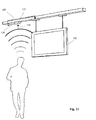
- the use of another terminal in the form of an infrared receiver 108 with a display 110 is shown in Fig.10.
- the display 110 (or a suitable Monitor) is used for playback of text and image information that has a high Require storage space and require a high transfer rate.
- a Transmission over the data line 112 of the busbar system is therefore not meaningful.
- the actual data is therefore from an infrared transmitter 116, which a memory 118 is coupled to the infrared receiver 108 of the display 110 transmitted, wherein the control is carried out via the data line 112 of the busbar.
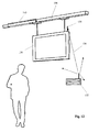
- the information may also be contained in a memory included in the display 120 is integrated. This case is shown in FIG. 11.
- a sensor 122 takes Environment information, e.g. the noise level. This is indicated by an arrow 124 shown.
- the information is passed on to the central control unit. This is shown by an arrow 126.
- the control unit in turn initiates commands to Adjust the volume to the display 120. This is indicated by an arrow 128 shown.
- the brightness can be regulated by means of a control Brightness sensor can be adjusted.
- the system of Figure 11 is particularly well suited for use as a billboard for information texts, departure times at the airport terminal, but also for advertising recordings. It can work together with the display Presence and counting systems are used, which provide information about the number of Delivered persons. This is particularly interesting for the advertising industry.
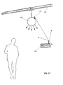
- Fig.12 also a display 130 is shown.
- the data is using an external video transmitter 132 to a receiver 136.
- multiple displays can Receive video information.
- control commands from the central control unit can via the busbar 138 in addition to the power supply and a selection and Controlling the displays done. This is shown by an arrow 140.
- the control of the displays may be based on information provided by Sensors are recorded.
- Fig.13 an application is shown in which a public address system 142 to the Busbar 144 is connected.
- the sound system receives in the shown Representation information by means of an infrared receiver 146 of the data from a Infrared transmitter 148 receives.
- Volume, type and extent of radiated Audio information can again be controlled by the central control unit. In conjunction with a localization system as described with reference to FIG was, this can be a locally limited exclamation of the person sought.
- the selected sound system 142 automatically to the Radio channel switched the exclamation, while the rest of the system is not affected is.
- the volume of the sound system can also vary depending on the signals a noise level sensor or a presence sensor are set.
- the applications described above require terminals that are in one Busbar system can be used.
- the terminals can communicate with each other combined and changed. Add or remove devices can be made by the layman.
- Such a terminal is a Signal light. This is shown in FIG. 14.
- the signal light 150 receives its data from the data line of the bus bar 152, which implements it (without feedback). This is shown by an arrow 154.
- a luminous surface 156 which consists of a variety is composed of light-emitting diodes, it may vary depending on the data received any color will light up or blink.
- a suitable symbol are formed, such as an arrow, in the appropriate direction indicates which the instructed visitor should follow. By the combination of arrow and Number, letter or color, which light up alternately, can also be several Persons are directed.
- This form of the Visitor guidance comes from a prepared database maintained by staff at the Reception or by the visitor himself to be activated at a computer terminal by simply the desired destination is selected. On the monitor is then the letter or the Number to be followed to reach the selected destination.
- Analogous to a personal guidance module on a visual basis is also a Wegleitmodul or passenger orientation module provided on an acoustic basis. This is special suitable for the blind and visually impaired.
- a device is 160 shown.
- the device 160 consists of the combination of a distance or Motion detector 162 with a speaker 166.
- the device is located on the busbar 168th If a person or a movement is registered, sounds softly but for the Short range loud enough a brief information about the location.
- the device is also in Shopfitting applicable. Customers are then targeted to the products in the location Near field pointed. Together with a sensor, for example a distance detector, can also highlight lighting on appropriate goods and shelves to be activated.
- the safety module is connectable to the ballast or integrated into the ballast. He exists in essential from a fuse. With the installation of a safety module should be prevented that in case of defects in a terminal contact between the Power line of the data line is made. The data line can then be virtually free be designed accessible and needs due to the low flowing currents should not be secured against accidental contact by the user.
- the security module is designed as an adapter, which by a simple Plug connection can be connected.
Applications Claiming Priority (2)
| Application Number | Priority Date | Filing Date | Title |
|---|---|---|---|
| DE10212232 | 2002-03-19 | ||
| DE10212232A DE10212232A1 (de) | 2002-03-19 | 2002-03-19 | Stromschiene mit Datenleitung |
Publications (3)
| Publication Number | Publication Date |
|---|---|
| EP1349437A2 true EP1349437A2 (fr) | 2003-10-01 |
| EP1349437A3 EP1349437A3 (fr) | 2004-11-10 |
| EP1349437B1 EP1349437B1 (fr) | 2010-05-26 |
Family
ID=27797938
Family Applications (1)
| Application Number | Title | Priority Date | Filing Date |
|---|---|---|---|
| EP03090066A Expired - Lifetime EP1349437B1 (fr) | 2002-03-19 | 2003-03-14 | Rail avec bus de données |
Country Status (7)
| Country | Link |
|---|---|
| US (1) | US6933444B2 (fr) |
| EP (1) | EP1349437B1 (fr) |
| AT (1) | ATE469531T1 (fr) |
| AU (1) | AU2003201014B2 (fr) |
| CA (1) | CA2422399C (fr) |
| DE (2) | DE10212232A1 (fr) |
| ES (1) | ES2345609T3 (fr) |
Cited By (6)
| Publication number | Priority date | Publication date | Assignee | Title |
|---|---|---|---|---|
| WO2008145204A1 (fr) * | 2007-05-25 | 2008-12-04 | Cooper Crouse-Hinds Gmbh | Dispositif d'éclairage et module de rail |
| EP2287978A1 (fr) * | 2009-08-17 | 2011-02-23 | Zumtobel Lighting GmbH | Système de rails conducteurs doté d'une prise à double face |
| EP2687992A1 (fr) * | 2012-07-18 | 2014-01-22 | Google Inc. | Procédé de déclassement automatique de participants à un réseau |
| WO2014122591A3 (fr) * | 2013-02-07 | 2015-05-21 | Koninklijke Philips N.V. | Système de distribution de puissance et de données |
| IT201900021723A1 (it) * | 2019-11-20 | 2021-05-20 | Reggiani Illuminazione | Sistema di illuminazione |
| EP4063726A1 (fr) * | 2021-03-25 | 2022-09-28 | H4X e.U. | Syst?me d'éclairage |
Families Citing this family (44)
| Publication number | Priority date | Publication date | Assignee | Title |
|---|---|---|---|---|
| US7632004B2 (en) * | 2004-07-06 | 2009-12-15 | Tseng-Lu Chien | LED night light with more than 1 optics means |
| US20050169015A1 (en) * | 2003-09-18 | 2005-08-04 | Luk John F. | LED color changing luminaire and track light system |
| FR2874444A1 (fr) * | 2004-12-03 | 2006-02-24 | France Telecom | Procede et systeme de guidage par liaison radio courte distance |
| DE102005008996B4 (de) * | 2005-01-21 | 2014-02-13 | Tridonic Gmbh & Co Kg | Verfahren und Vorrichtung zum Einstellen eines kontinuierlichen Dimmbetriebes oder eines Dimmbetriebes mit nur zwei Pegeln |
| DE102005019632A1 (de) | 2005-04-26 | 2006-11-09 | Erco Leuchten Gmbh | Leuchte, Betriebsgerät, Stromschiene, Schaltungsanordnung und Stromschienen-Adapter |
| CN101325894B (zh) * | 2005-12-12 | 2010-12-29 | 皇家飞利浦电子股份有限公司 | 用于产生局部光的光系统和方法 |
| DE102006035557A1 (de) * | 2006-04-21 | 2007-11-15 | Erco Leuchten Gmbh | Leuchte |
| DE102006028074A1 (de) * | 2006-06-19 | 2007-12-20 | Münchner Hybrid Systemtechnik GmbH | Leuchtensystem |
| US8807796B2 (en) | 2006-09-12 | 2014-08-19 | Huizhou Light Engine Ltd. | Integrally formed light emitting diode light wire and uses thereof |
| US8567992B2 (en) * | 2006-09-12 | 2013-10-29 | Huizhou Light Engine Ltd. | Integrally formed light emitting diode light wire and uses thereof |
| US8052303B2 (en) * | 2006-09-12 | 2011-11-08 | Huizhou Light Engine Ltd. | Integrally formed single piece light emitting diode light wire and uses thereof |
| AU2007296902B2 (en) | 2006-09-12 | 2011-08-25 | Huizhou Light Engine Ltd. | Integrally formed single piece light emitting diode light wire |
| NL1033358C2 (nl) * | 2007-02-08 | 2008-08-11 | Stas Marinus Barbara Arnoldus | Railsysteem voor het ophangen en aansluiten van audiovisuele artikelen en verlichtingsartikelen, alsmede audiovisuele artikelen en verlichtingsartikelen geschikt om te worden opgenomen in een dergelijk railsysteem. |
| JP5450098B2 (ja) * | 2007-02-12 | 2014-03-26 | コーニンクレッカ フィリップス エヌ ヴェ | 照明システムのための制御モジュール、照明システム及び照明システムのための照明モジュール |
| CN101408297B (zh) * | 2007-10-12 | 2010-06-02 | 富准精密工业(深圳)有限公司 | 可远程监控的发光二极管灯具及其远程监控方法 |
| DE102007001000A1 (de) | 2007-12-05 | 2009-06-18 | Semperlux Aktiengesellschaft - Lichttechnische Werke - | Stromschiene mit Datenleitung |
| DE102008017509A1 (de) | 2008-04-04 | 2009-10-08 | Semperlux Aktiengesellschaft - Lichttechnische Werke - | Installation mit DALI-Bus |
| US20090315478A1 (en) * | 2008-06-19 | 2009-12-24 | Mccolgin Jerry L | Lighting system having master and slave lighting fixtures |
| US8258721B2 (en) * | 2008-09-16 | 2012-09-04 | Evolution Lighting, Llc | Remotely controllable track lighting system |
| WO2010147602A1 (fr) * | 2009-06-18 | 2010-12-23 | Litelab Corp. | Système de distribution de puissance pour éclairage hid, led, ou sur rail fluorescent |
| CN102612623A (zh) * | 2009-09-11 | 2012-07-25 | D·S·斯皮罗 | 用于顶棚安装系统的方法和设备 |
| DE102009044063B3 (de) * | 2009-09-21 | 2011-03-24 | Semperlux Aktiengesellschaft - Lichttechnische Werke - | Anordnung zur Vermeidung oder Verringerung der Schädigung von strahlungsempfindlichen Exponanten, insbesondere in Ausstellungen oder Museen |
| US8344655B2 (en) * | 2010-01-25 | 2013-01-01 | Altman Stage Lighting Co., Inc. | Power and data track lighting system |
| US9328882B2 (en) * | 2010-09-13 | 2016-05-03 | Exposure Illumination Architects, Inc. | Methods and apparatus for ceiling mounted systems |
| US9149350B2 (en) | 2010-12-01 | 2015-10-06 | David J. Ahearn | Track lighting system |
| CN102647821B (zh) * | 2011-02-18 | 2014-12-03 | 光宝电子(广州)有限公司 | 灯具 |
| DE102011017582A1 (de) * | 2011-04-27 | 2012-10-31 | Zumtobel Lighting Gmbh | Anordnung zur Erfassung des Tageslichts und System und Verfahren zur tageslichtabhängigen Steuerung |
| JP5796167B2 (ja) * | 2011-06-07 | 2015-10-21 | パナソニックIpマネジメント株式会社 | 照明システム |
| WO2013124779A1 (fr) * | 2012-02-22 | 2013-08-29 | Koninklijke Philips N.V. | Connecteur électrique |
| US20130308303A1 (en) * | 2012-05-17 | 2013-11-21 | D2 Lighting | Lighting System for an Architectural Ceiling Structure |
| US9360196B2 (en) | 2012-06-15 | 2016-06-07 | Rtc Industries, Inc. | Low voltage power supply for a merchandise display system |
| US9225131B2 (en) * | 2012-06-15 | 2015-12-29 | RTC Industries, Incorporated | Low voltage power supply with magnetic connections |
| BR112015021284A2 (pt) | 2013-03-07 | 2017-07-18 | Koninklijke Philips Nv | sistema de iluminação, calha adequada para uso no sistema de iluminação e módulo de iluminação adequado para uso no sistema de iluminação |
| US9269256B2 (en) * | 2013-12-17 | 2016-02-23 | Lenovo Enterprise Solutions (Singapore) Pte. Ltd. | Dynamic activation of service indicators based upon service personnel proximity |
| US20150308642A1 (en) * | 2014-04-23 | 2015-10-29 | General Led, Inc. | Self-Aiming Track Light Fixture System and Method |
| DE102015112838A1 (de) | 2015-08-05 | 2017-02-09 | Selux Ag | Beleuchtungsanordnung für Stromschienen |
| WO2017066666A1 (fr) | 2015-10-16 | 2017-04-20 | Hubbell Incorporated | Luminaire modulaire à très grande hauteur |
| DE202016004226U1 (de) | 2016-07-06 | 2016-11-11 | Helmut Senkel | Schienensystem mit verfahrbaren Verbrauchern |
| IT201600107003A1 (it) * | 2016-10-24 | 2018-04-24 | Bticino Spa | Impianto elettrico a vista a bassissima tensione. |
| DE202016007008U1 (de) | 2016-11-15 | 2017-02-23 | Helmut Senkel | Induktiv betriebenes Stromschienensystem |
| JP2018163319A (ja) * | 2017-03-27 | 2018-10-18 | 東芝ライテック株式会社 | 照明ダクトに取り付ける情報提供装置、および照明ダクトシステム |
| DE202017102463U1 (de) * | 2017-04-26 | 2018-07-27 | Zumtobel Lighting Gmbh | Leuchtensystem |
| EP3742939A1 (fr) | 2018-01-26 | 2020-12-02 | RTC Industries, Inc. | Système d'alimentation basse tension pour un dispositif de présentation de marchandises |
| DE102018105749A1 (de) * | 2018-03-13 | 2019-09-19 | Osram Gmbh | Stromschienensystem und stromschienenanordnung zur datenübertragung |
Citations (1)
| Publication number | Priority date | Publication date | Assignee | Title |
|---|---|---|---|---|
| DE4020807A1 (de) | 1990-06-29 | 1992-01-02 | Siemens Ag | Anzeigefeld zur ein- und ausgabe von daten |
Family Cites Families (14)
| Publication number | Priority date | Publication date | Assignee | Title |
|---|---|---|---|---|
| JPS62276689A (ja) | 1986-05-26 | 1987-12-01 | ホーチキ株式会社 | 避難誘導表示器の制御装置 |
| GB2215105A (en) * | 1988-02-16 | 1989-09-13 | Richard William Henry Ford | Personnel evacuation system |
| DE3812465C2 (de) | 1988-04-12 | 1998-10-08 | Semperlux Gmbh | Stromschiene |
| US5241380A (en) * | 1991-05-31 | 1993-08-31 | Video Sentry Corporation | Track mounted surveillance system having multiple use conductors |
| US5336849A (en) * | 1992-01-17 | 1994-08-09 | The Wiremold Company | Raceway assembly for power and communications conductors |
| DE4241862C2 (de) * | 1992-12-11 | 2001-03-01 | Ceag Sicherheitstechnik Gmbh | Sicherheitssystem sowie Verfahren, mit dem das Sicherheitssystem betrieben wird |
| FI101758B1 (fi) * | 1996-02-16 | 1998-08-14 | Nordic Aluminium Oyj | Sovitelma kosketinkiskon yhteydessä |
| DE19615840A1 (de) * | 1996-04-20 | 1997-10-30 | Bosch Gmbh Robert | Elektrisches Hausgerät |
| DE19819279C1 (de) | 1998-04-30 | 1999-03-25 | Dorma Gmbh & Co Kg | Antriebssystem für ein Trennwandsystem |
| DE29906910U1 (de) * | 1999-04-16 | 2000-08-24 | Busch Dieter & Co Prueftech | Hängevorrichtung für elektrisch zu kontaktierende Gegenstände |
| DE59912599D1 (de) * | 1998-11-30 | 2005-11-03 | Busch Dieter & Co Prueftech | Überwachungssystem, basierend auf einer Hängevorrichtung für elektrisch zu kontaktierende Gegenstände |
| DE29917691U1 (de) * | 1999-10-07 | 2000-04-06 | Schlagheck Design Gmbh | Adapter zur Halterung von Lichtquellen |
| JP2001273814A (ja) * | 2000-03-28 | 2001-10-05 | Matsushita Electric Works Ltd | 熱線センサ付き自動スイッチ |
| DE10018073A1 (de) | 2000-03-31 | 2001-10-04 | Briloner Leuchten Gmbh | Beleuchtungsvorrichtung |
-
2002
- 2002-03-19 DE DE10212232A patent/DE10212232A1/de not_active Ceased
-
2003
- 2003-03-14 AU AU2003201014A patent/AU2003201014B2/en not_active Ceased
- 2003-03-14 DE DE50312732T patent/DE50312732D1/de not_active Expired - Lifetime
- 2003-03-14 ES ES03090066T patent/ES2345609T3/es not_active Expired - Lifetime
- 2003-03-14 AT AT03090066T patent/ATE469531T1/de active
- 2003-03-14 EP EP03090066A patent/EP1349437B1/fr not_active Expired - Lifetime
- 2003-03-18 CA CA2422399A patent/CA2422399C/fr not_active Expired - Fee Related
- 2003-03-18 US US10/390,007 patent/US6933444B2/en not_active Expired - Lifetime
Patent Citations (1)
| Publication number | Priority date | Publication date | Assignee | Title |
|---|---|---|---|---|
| DE4020807A1 (de) | 1990-06-29 | 1992-01-02 | Siemens Ag | Anzeigefeld zur ein- und ausgabe von daten |
Cited By (12)
| Publication number | Priority date | Publication date | Assignee | Title |
|---|---|---|---|---|
| WO2008145204A1 (fr) * | 2007-05-25 | 2008-12-04 | Cooper Crouse-Hinds Gmbh | Dispositif d'éclairage et module de rail |
| RU2448298C2 (ru) * | 2007-05-25 | 2012-04-20 | Купер Краус-Хайндс Гмбх | Осветительная арматура и реечный модуль |
| US8226279B2 (en) | 2007-05-25 | 2012-07-24 | Cooper Crouse-Hinds Gmbh | Lighting fixture and rail module |
| CN101680643B (zh) * | 2007-05-25 | 2012-12-26 | 库珀·克劳斯-海因兹有限责任公司 | 灯具和导轨模块 |
| EP2287978A1 (fr) * | 2009-08-17 | 2011-02-23 | Zumtobel Lighting GmbH | Système de rails conducteurs doté d'une prise à double face |
| EP2687992A1 (fr) * | 2012-07-18 | 2014-01-22 | Google Inc. | Procédé de déclassement automatique de participants à un réseau |
| US8706934B2 (en) | 2012-07-18 | 2014-04-22 | Google Inc. | System and method for automatic decommissioning of network participants by closing select circuits in order to change a plurality of mechanical states of the network participants |
| US9230762B2 (en) | 2012-07-18 | 2016-01-05 | Google Inc. | System for automatic decommissioning of network participants wherein device has a deflective member having various states and various lengths |
| US9569331B2 (en) | 2012-07-18 | 2017-02-14 | Google Inc. | System for automatic decommissioning of network participants based on pressure applied to compression element within the device |
| WO2014122591A3 (fr) * | 2013-02-07 | 2015-05-21 | Koninklijke Philips N.V. | Système de distribution de puissance et de données |
| IT201900021723A1 (it) * | 2019-11-20 | 2021-05-20 | Reggiani Illuminazione | Sistema di illuminazione |
| EP4063726A1 (fr) * | 2021-03-25 | 2022-09-28 | H4X e.U. | Syst?me d'éclairage |
Also Published As
| Publication number | Publication date |
|---|---|
| CA2422399C (fr) | 2012-02-07 |
| CA2422399A1 (fr) | 2003-09-19 |
| EP1349437A3 (fr) | 2004-11-10 |
| ES2345609T3 (es) | 2010-09-28 |
| DE50312732D1 (de) | 2010-07-08 |
| US6933444B2 (en) | 2005-08-23 |
| AU2003201014A1 (en) | 2003-10-16 |
| AU2003201014B2 (en) | 2006-12-21 |
| ATE469531T1 (de) | 2010-06-15 |
| US20030179578A1 (en) | 2003-09-25 |
| EP1349437B1 (fr) | 2010-05-26 |
| DE10212232A1 (de) | 2003-10-09 |
Similar Documents
| Publication | Publication Date | Title |
|---|---|---|
| EP1349437B1 (fr) | Rail avec bus de données | |
| DE102008017656A1 (de) | Notlichtleuchte und Rettungszeichen | |
| DE4124794C2 (de) | Beleuchtungsanlage mit verfahrbaren, eine Dimm- und Schalteinheit enthaltenden Leuchtkörpern | |
| EP2382418B1 (fr) | Systeme modulaire de chauffage et d'eclairage | |
| EP1008971B1 (fr) | Système de surveillance avec dispositif de suspension pour objets électroconducteurs | |
| DE19544027A1 (de) | Bussystem, insbesondere zur elektrischen Installation | |
| DE102005050209A1 (de) | Vorrichtung zur Einspeisung eines Videosignals in eine Anzeigevorrichtung und Betriebsverfahren hierfür | |
| DE20221024U1 (de) | Stromschiene mit Datenleitung | |
| DE60223277T2 (de) | System und verfahren zur steuerung des betriebs elektrischer geräte | |
| DE10001252B4 (de) | Überwachungssystem | |
| DE202020103910U1 (de) | Intelligente Fluchtweganzeigevorrichtung für optisch-akustische Fluchtweglenkung, sowie Wegleitsystem | |
| DE102014220553A1 (de) | Multifunktionseinheit und Objektüberwachungssystem | |
| EP3557548A1 (fr) | Module combiné destiné au montage mural ou au plafond | |
| EP3201703B1 (fr) | Commande pour des éclairages de bâtiment et d'autres installations techniques domestiques | |
| WO2018229272A1 (fr) | Dispositif pour pièces d'installation électriques | |
| DE19756705C2 (de) | Beleuchtungssystem | |
| EP3664304B1 (fr) | Entrée et sortie de données et transport de données par l'intermédiaire d'une conduite d'alimentation électrique des systèmes d'éclairage | |
| DE102014220059A1 (de) | Steuerung für Gebäudebeleuchtungen und andere Haustechnikinstallationen | |
| DE102014220055A1 (de) | Steuerung für Gebäudebeleuchtungen und andere Haustechnikinstallationen | |
| EP1437927A2 (fr) | Luminaire | |
| EP2473888B1 (fr) | Appareil de commande à écran de visualisation | |
| DE3900605A1 (de) | Bewegungsmelder | |
| EP2530933A2 (fr) | Appareil de formation et de stockage d'images | |
| DE102004063796A1 (de) | Verfahren und Anordnung zur Fernübertragung von Daten, die wenigstens Bilddaten umfassen | |
| DE102021210512A1 (de) | Ansteuerverfahren zum Verändern der Helligkeit in der Umgebung eines Elektrogeräts |
Legal Events
| Date | Code | Title | Description |
|---|---|---|---|
| PUAI | Public reference made under article 153(3) epc to a published international application that has entered the european phase |
Free format text: ORIGINAL CODE: 0009012 |
|
| AK | Designated contracting states |
Kind code of ref document: A2 Designated state(s): AT BE BG CH CY CZ DE DK EE ES FI FR GB GR HU IE IT LI LU MC NL PT RO SE SI SK TR |
|
| AX | Request for extension of the european patent |
Extension state: AL LT LV MK |
|
| PUAL | Search report despatched |
Free format text: ORIGINAL CODE: 0009013 |
|
| AK | Designated contracting states |
Kind code of ref document: A3 Designated state(s): AT BE BG CH CY CZ DE DK EE ES FI FR GB GR HU IE IT LI LU MC NL PT RO SE SI SK TR |
|
| AX | Request for extension of the european patent |
Extension state: AL LT LV MK |
|
| 17P | Request for examination filed |
Effective date: 20050504 |
|
| AKX | Designation fees paid |
Designated state(s): AT BE BG CH CY CZ DE DK EE ES FI FR GB GR HU IE IT LI LU MC NL PT RO SE SI SK TR |
|
| 17Q | First examination report despatched |
Effective date: 20080812 |
|
| GRAP | Despatch of communication of intention to grant a patent |
Free format text: ORIGINAL CODE: EPIDOSNIGR1 |
|
| GRAS | Grant fee paid |
Free format text: ORIGINAL CODE: EPIDOSNIGR3 |
|
| GRAA | (expected) grant |
Free format text: ORIGINAL CODE: 0009210 |
|
| AK | Designated contracting states |
Kind code of ref document: B1 Designated state(s): AT BE BG CH CY CZ DE DK EE ES FI FR GB GR HU IE IT LI LU MC NL PT RO SE SI SK TR |
|
| REG | Reference to a national code |
Ref country code: GB Ref legal event code: FG4D Free format text: NOT ENGLISH |
|
| REG | Reference to a national code |
Ref country code: CH Ref legal event code: EP |
|
| REG | Reference to a national code |
Ref country code: IE Ref legal event code: FG4D Free format text: LANGUAGE OF EP DOCUMENT: GERMAN |
|
| REF | Corresponds to: |
Ref document number: 50312732 Country of ref document: DE Date of ref document: 20100708 Kind code of ref document: P |
|
| REG | Reference to a national code |
Ref country code: NL Ref legal event code: VDEP Effective date: 20100526 |
|
| REG | Reference to a national code |
Ref country code: ES Ref legal event code: FG2A Ref document number: 2345609 Country of ref document: ES Kind code of ref document: T3 |
|
| PG25 | Lapsed in a contracting state [announced via postgrant information from national office to epo] |
Ref country code: SE Free format text: LAPSE BECAUSE OF FAILURE TO SUBMIT A TRANSLATION OF THE DESCRIPTION OR TO PAY THE FEE WITHIN THE PRESCRIBED TIME-LIMIT Effective date: 20100526 |
|
| PG25 | Lapsed in a contracting state [announced via postgrant information from national office to epo] |
Ref country code: FI Free format text: LAPSE BECAUSE OF FAILURE TO SUBMIT A TRANSLATION OF THE DESCRIPTION OR TO PAY THE FEE WITHIN THE PRESCRIBED TIME-LIMIT Effective date: 20100526 Ref country code: SI Free format text: LAPSE BECAUSE OF FAILURE TO SUBMIT A TRANSLATION OF THE DESCRIPTION OR TO PAY THE FEE WITHIN THE PRESCRIBED TIME-LIMIT Effective date: 20100526 |
|
| PG25 | Lapsed in a contracting state [announced via postgrant information from national office to epo] |
Ref country code: GR Free format text: LAPSE BECAUSE OF FAILURE TO SUBMIT A TRANSLATION OF THE DESCRIPTION OR TO PAY THE FEE WITHIN THE PRESCRIBED TIME-LIMIT Effective date: 20100827 Ref country code: CY Free format text: LAPSE BECAUSE OF FAILURE TO SUBMIT A TRANSLATION OF THE DESCRIPTION OR TO PAY THE FEE WITHIN THE PRESCRIBED TIME-LIMIT Effective date: 20100526 |
|
| REG | Reference to a national code |
Ref country code: IE Ref legal event code: FD4D |
|
| PG25 | Lapsed in a contracting state [announced via postgrant information from national office to epo] |
Ref country code: DK Free format text: LAPSE BECAUSE OF FAILURE TO SUBMIT A TRANSLATION OF THE DESCRIPTION OR TO PAY THE FEE WITHIN THE PRESCRIBED TIME-LIMIT Effective date: 20100526 Ref country code: EE Free format text: LAPSE BECAUSE OF FAILURE TO SUBMIT A TRANSLATION OF THE DESCRIPTION OR TO PAY THE FEE WITHIN THE PRESCRIBED TIME-LIMIT Effective date: 20100526 Ref country code: IE Free format text: LAPSE BECAUSE OF FAILURE TO SUBMIT A TRANSLATION OF THE DESCRIPTION OR TO PAY THE FEE WITHIN THE PRESCRIBED TIME-LIMIT Effective date: 20100526 Ref country code: NL Free format text: LAPSE BECAUSE OF FAILURE TO SUBMIT A TRANSLATION OF THE DESCRIPTION OR TO PAY THE FEE WITHIN THE PRESCRIBED TIME-LIMIT Effective date: 20100526 Ref country code: PT Free format text: LAPSE BECAUSE OF FAILURE TO SUBMIT A TRANSLATION OF THE DESCRIPTION OR TO PAY THE FEE WITHIN THE PRESCRIBED TIME-LIMIT Effective date: 20100927 |
|
| PG25 | Lapsed in a contracting state [announced via postgrant information from national office to epo] |
Ref country code: SK Free format text: LAPSE BECAUSE OF FAILURE TO SUBMIT A TRANSLATION OF THE DESCRIPTION OR TO PAY THE FEE WITHIN THE PRESCRIBED TIME-LIMIT Effective date: 20100526 Ref country code: RO Free format text: LAPSE BECAUSE OF FAILURE TO SUBMIT A TRANSLATION OF THE DESCRIPTION OR TO PAY THE FEE WITHIN THE PRESCRIBED TIME-LIMIT Effective date: 20100526 Ref country code: CZ Free format text: LAPSE BECAUSE OF FAILURE TO SUBMIT A TRANSLATION OF THE DESCRIPTION OR TO PAY THE FEE WITHIN THE PRESCRIBED TIME-LIMIT Effective date: 20100526 |
|
| PG25 | Lapsed in a contracting state [announced via postgrant information from national office to epo] |
Ref country code: IT Free format text: LAPSE BECAUSE OF FAILURE TO SUBMIT A TRANSLATION OF THE DESCRIPTION OR TO PAY THE FEE WITHIN THE PRESCRIBED TIME-LIMIT Effective date: 20100526 |
|
| PLBE | No opposition filed within time limit |
Free format text: ORIGINAL CODE: 0009261 |
|
| STAA | Information on the status of an ep patent application or granted ep patent |
Free format text: STATUS: NO OPPOSITION FILED WITHIN TIME LIMIT |
|
| 26N | No opposition filed |
Effective date: 20110301 |
|
| REG | Reference to a national code |
Ref country code: DE Ref legal event code: R097 Ref document number: 50312732 Country of ref document: DE Effective date: 20110228 |
|
| BERE | Be: lapsed |
Owner name: SEMPERLUX AKTIENGESELLSCHAFT, LICHTTECHNISCHE WER Effective date: 20110331 |
|
| PG25 | Lapsed in a contracting state [announced via postgrant information from national office to epo] |
Ref country code: MC Free format text: LAPSE BECAUSE OF NON-PAYMENT OF DUE FEES Effective date: 20110331 |
|
| REG | Reference to a national code |
Ref country code: CH Ref legal event code: PL |
|
| PG25 | Lapsed in a contracting state [announced via postgrant information from national office to epo] |
Ref country code: BE Free format text: LAPSE BECAUSE OF NON-PAYMENT OF DUE FEES Effective date: 20110331 |
|
| PG25 | Lapsed in a contracting state [announced via postgrant information from national office to epo] |
Ref country code: LI Free format text: LAPSE BECAUSE OF NON-PAYMENT OF DUE FEES Effective date: 20110331 Ref country code: CH Free format text: LAPSE BECAUSE OF NON-PAYMENT OF DUE FEES Effective date: 20110331 |
|
| REG | Reference to a national code |
Ref country code: DE Ref legal event code: R082 Ref document number: 50312732 Country of ref document: DE Representative=s name: PATENTANWAELTE WEISSE & WOLGAST, DE |
|
| REG | Reference to a national code |
Ref country code: DE Ref legal event code: R081 Ref document number: 50312732 Country of ref document: DE Owner name: SELUX AKTIENGESELLSCHAFT, DE Free format text: FORMER OWNER: SEMPERLUX AKTIENGESELLSCHAFT - LICHTTECHNISCHE WERKE -, 12277 BERLIN, DE Effective date: 20120919 Ref country code: DE Ref legal event code: R082 Ref document number: 50312732 Country of ref document: DE Representative=s name: WEISSE, RENATE, DIPL.-PHYS. DR.-ING., DE Effective date: 20120919 Ref country code: DE Ref legal event code: R082 Ref document number: 50312732 Country of ref document: DE Representative=s name: PATENTANWAELTE WEISSE & WOLGAST, DE Effective date: 20120919 |
|
| REG | Reference to a national code |
Ref country code: AT Ref legal event code: MM01 Ref document number: 469531 Country of ref document: AT Kind code of ref document: T Effective date: 20110314 |
|
| PG25 | Lapsed in a contracting state [announced via postgrant information from national office to epo] |
Ref country code: AT Free format text: LAPSE BECAUSE OF NON-PAYMENT OF DUE FEES Effective date: 20110314 |
|
| PG25 | Lapsed in a contracting state [announced via postgrant information from national office to epo] |
Ref country code: LU Free format text: LAPSE BECAUSE OF NON-PAYMENT OF DUE FEES Effective date: 20110314 |
|
| REG | Reference to a national code |
Ref country code: DE Ref legal event code: R082 Ref document number: 50312732 Country of ref document: DE Representative=s name: WEISSE, RENATE, DIPL.-PHYS. DR.-ING., DE |
|
| PG25 | Lapsed in a contracting state [announced via postgrant information from national office to epo] |
Ref country code: BG Free format text: LAPSE BECAUSE OF FAILURE TO SUBMIT A TRANSLATION OF THE DESCRIPTION OR TO PAY THE FEE WITHIN THE PRESCRIBED TIME-LIMIT Effective date: 20100826 Ref country code: TR Free format text: LAPSE BECAUSE OF FAILURE TO SUBMIT A TRANSLATION OF THE DESCRIPTION OR TO PAY THE FEE WITHIN THE PRESCRIBED TIME-LIMIT Effective date: 20100526 |
|
| PG25 | Lapsed in a contracting state [announced via postgrant information from national office to epo] |
Ref country code: HU Free format text: LAPSE BECAUSE OF FAILURE TO SUBMIT A TRANSLATION OF THE DESCRIPTION OR TO PAY THE FEE WITHIN THE PRESCRIBED TIME-LIMIT Effective date: 20100526 |
|
| REG | Reference to a national code |
Ref country code: FR Ref legal event code: PLFP Year of fee payment: 13 |
|
| REG | Reference to a national code |
Ref country code: FR Ref legal event code: PLFP Year of fee payment: 14 |
|
| REG | Reference to a national code |
Ref country code: FR Ref legal event code: PLFP Year of fee payment: 15 |
|
| PGFP | Annual fee paid to national office [announced via postgrant information from national office to epo] |
Ref country code: DE Payment date: 20170328 Year of fee payment: 15 |
|
| PGFP | Annual fee paid to national office [announced via postgrant information from national office to epo] |
Ref country code: GB Payment date: 20170323 Year of fee payment: 15 |
|
| PGFP | Annual fee paid to national office [announced via postgrant information from national office to epo] |
Ref country code: FR Payment date: 20170327 Year of fee payment: 15 |
|
| PGFP | Annual fee paid to national office [announced via postgrant information from national office to epo] |
Ref country code: ES Payment date: 20170327 Year of fee payment: 15 |
|
| REG | Reference to a national code |
Ref country code: DE Ref legal event code: R119 Ref document number: 50312732 Country of ref document: DE |
|
| GBPC | Gb: european patent ceased through non-payment of renewal fee |
Effective date: 20180314 |
|
| PG25 | Lapsed in a contracting state [announced via postgrant information from national office to epo] |
Ref country code: DE Free format text: LAPSE BECAUSE OF NON-PAYMENT OF DUE FEES Effective date: 20181002 |
|
| PG25 | Lapsed in a contracting state [announced via postgrant information from national office to epo] |
Ref country code: GB Free format text: LAPSE BECAUSE OF NON-PAYMENT OF DUE FEES Effective date: 20180314 |
|
| PG25 | Lapsed in a contracting state [announced via postgrant information from national office to epo] |
Ref country code: FR Free format text: LAPSE BECAUSE OF NON-PAYMENT OF DUE FEES Effective date: 20180331 |
|
| REG | Reference to a national code |
Ref country code: ES Ref legal event code: FD2A Effective date: 20190911 |
|
| PG25 | Lapsed in a contracting state [announced via postgrant information from national office to epo] |
Ref country code: ES Free format text: LAPSE BECAUSE OF NON-PAYMENT OF DUE FEES Effective date: 20180315 |