EP1349437A2 - Conductor rail system with control line - Google Patents
Conductor rail system with control line Download PDFInfo
- Publication number
- EP1349437A2 EP1349437A2 EP03090066A EP03090066A EP1349437A2 EP 1349437 A2 EP1349437 A2 EP 1349437A2 EP 03090066 A EP03090066 A EP 03090066A EP 03090066 A EP03090066 A EP 03090066A EP 1349437 A2 EP1349437 A2 EP 1349437A2
- Authority
- EP
- European Patent Office
- Prior art keywords
- sensor
- busbar
- terminals
- central control
- conductor rail
- Prior art date
- Legal status (The legal status is an assumption and is not a legal conclusion. Google has not performed a legal analysis and makes no representation as to the accuracy of the status listed.)
- Granted
Links
Images


Classifications
-
- F—MECHANICAL ENGINEERING; LIGHTING; HEATING; WEAPONS; BLASTING
- F21—LIGHTING
- F21V—FUNCTIONAL FEATURES OR DETAILS OF LIGHTING DEVICES OR SYSTEMS THEREOF; STRUCTURAL COMBINATIONS OF LIGHTING DEVICES WITH OTHER ARTICLES, NOT OTHERWISE PROVIDED FOR
- F21V21/00—Supporting, suspending, or attaching arrangements for lighting devices; Hand grips
- F21V21/14—Adjustable mountings
- F21V21/15—Adjustable mountings specially adapted for power operation, e.g. by remote control
-
- H—ELECTRICITY
- H01—ELECTRIC ELEMENTS
- H01R—ELECTRICALLY-CONDUCTIVE CONNECTIONS; STRUCTURAL ASSOCIATIONS OF A PLURALITY OF MUTUALLY-INSULATED ELECTRICAL CONNECTING ELEMENTS; COUPLING DEVICES; CURRENT COLLECTORS
- H01R25/00—Coupling parts adapted for simultaneous co-operation with two or more identical counterparts, e.g. for distributing energy to two or more circuits
- H01R25/14—Rails or bus-bars constructed so that the counterparts can be connected thereto at any point along their length
-
- H—ELECTRICITY
- H05—ELECTRIC TECHNIQUES NOT OTHERWISE PROVIDED FOR
- H05B—ELECTRIC HEATING; ELECTRIC LIGHT SOURCES NOT OTHERWISE PROVIDED FOR; CIRCUIT ARRANGEMENTS FOR ELECTRIC LIGHT SOURCES, IN GENERAL
- H05B47/00—Circuit arrangements for operating light sources in general, i.e. where the type of light source is not relevant
- H05B47/10—Controlling the light source
- H05B47/175—Controlling the light source by remote control
- H05B47/18—Controlling the light source by remote control via data-bus transmission
-
- H—ELECTRICITY
- H05—ELECTRIC TECHNIQUES NOT OTHERWISE PROVIDED FOR
- H05B—ELECTRIC HEATING; ELECTRIC LIGHT SOURCES NOT OTHERWISE PROVIDED FOR; CIRCUIT ARRANGEMENTS FOR ELECTRIC LIGHT SOURCES, IN GENERAL
- H05B47/00—Circuit arrangements for operating light sources in general, i.e. where the type of light source is not relevant
- H05B47/10—Controlling the light source
- H05B47/175—Controlling the light source by remote control
- H05B47/19—Controlling the light source by remote control via wireless transmission
- H05B47/195—Controlling the light source by remote control via wireless transmission the transmission using visible or infrared light
-
- F—MECHANICAL ENGINEERING; LIGHTING; HEATING; WEAPONS; BLASTING
- F21—LIGHTING
- F21V—FUNCTIONAL FEATURES OR DETAILS OF LIGHTING DEVICES OR SYSTEMS THEREOF; STRUCTURAL COMBINATIONS OF LIGHTING DEVICES WITH OTHER ARTICLES, NOT OTHERWISE PROVIDED FOR
- F21V21/00—Supporting, suspending, or attaching arrangements for lighting devices; Hand grips
- F21V21/34—Supporting elements displaceable along a guiding element
- F21V21/35—Supporting elements displaceable along a guiding element with direct electrical contact between the supporting element and electric conductors running along the guiding element
-
- F—MECHANICAL ENGINEERING; LIGHTING; HEATING; WEAPONS; BLASTING
- F21—LIGHTING
- F21V—FUNCTIONAL FEATURES OR DETAILS OF LIGHTING DEVICES OR SYSTEMS THEREOF; STRUCTURAL COMBINATIONS OF LIGHTING DEVICES WITH OTHER ARTICLES, NOT OTHERWISE PROVIDED FOR
- F21V23/00—Arrangement of electric circuit elements in or on lighting devices
- F21V23/04—Arrangement of electric circuit elements in or on lighting devices the elements being switches
- F21V23/0442—Arrangement of electric circuit elements in or on lighting devices the elements being switches activated by means of a sensor, e.g. motion or photodetectors
-
- H—ELECTRICITY
- H05—ELECTRIC TECHNIQUES NOT OTHERWISE PROVIDED FOR
- H05B—ELECTRIC HEATING; ELECTRIC LIGHT SOURCES NOT OTHERWISE PROVIDED FOR; CIRCUIT ARRANGEMENTS FOR ELECTRIC LIGHT SOURCES, IN GENERAL
- H05B47/00—Circuit arrangements for operating light sources in general, i.e. where the type of light source is not relevant
- H05B47/10—Controlling the light source
- H05B47/175—Controlling the light source by remote control
- H05B47/19—Controlling the light source by remote control via wireless transmission
Definitions
- the invention relates to a busbar system with a data line, comprising a or multiple terminals at any location in the busbar system are flexibly detachably connectable, with a common central control system is provided, and at least one of the terminals is a sensor or a receiver, with which signals can be received and via the data line to the central Control system are conductive.
- adjustable parameters include the selection of lights that are on and the desired brightness with which the lights shine.
- the lights are actuated by means of switches, for example on a door, which can also be configured as a dimmer. With these dimmers can the brightness the lights are set.
- busbar systems that allow luminaires to be flexibly powered To lay a layman in any number and position at desired positions.
- the Busbar consists of a mostly U-shaped metal profile, which in or on the Ceiling of a room is firmly attached. Inside the busbar are insulated Conductors provided. Each luminaire is provided with an adapter attached to the Busbar system is attached and by means of built-in contacts with the Power line is connected.
- Such busbar systems have the advantage that the Position of the lights can also be adjusted by the layman.
- the Busbar systems have the advantage that they are already installed in new buildings can, even if their use and according to the exact number, type and location the lamps used is not yet known. In such busbar systems However, the lights can not be controlled individually. It is therefore necessary to provide the lights with information about the desired operating state.
- Cable ducts are solid installed plastic pipes or profiles, in which a variety of power cables, Data lines and other cables can be stirred loosely.
- On the plastic pipe There are permanently integrated connections on which the cables laid in this way are tapped and energy or information can be obtained through a suitable interface can.
- the connections are permanently installed at predetermined points of the Cable channel. Additional connections can only be made through a specialist be installed comparatively large effort.
- EIB European Installation Bus
- the system is i.a. described in the publication "Daylight Dependent Lighting Systems Based on Installation Buses "by P.T. Knoop, Progress-Ber.VDI Series 6 No. 396 1998.
- Each connected light is in this system via a node with the power rail and the data line connected.
- the node has a data processing unit.
- the nodes are together with an information generator and a translator in an actuator provided which is fixedly connected to the busbar.
- everyone at the System connected node is doing with respect to the communication of connected devices equally.
- Each connected device is transmitter and Receiver of information communicated via a BUS system.
- a central control unit is not provided.
- the system is therefore suitable for quasi arbitrarily large applications such as the management of complex building services for large Building. However, the system is too expensive for many simpler applications consuming.
- the object is achieved in that the terminals individually are addressable without own control functions and and a data transfer after the master-slave principle exclusively between a terminal and the central Control system takes place.
- Information also in the opposite direction to the control computer.
- the Control computer can be the information provided by the sensor or receiver record, centrally process and the results to control other connected Provide terminals.
- the terminals are carried out according to cost.
- the terminals need no own data processing units.
- the already existing infrastructure for the Power supply is made available simultaneously for data communication, wherein a particularly high level of flexibility is guaranteed, since the devices from the layman without special effort can be installed. This makes use in such Particularly attractive cases in which the type of use changes frequently and the Installations are each provided at different locations.
- DALI Digital Addressable Lighting Interface
- terminals first of all lights are particularly suitable. It can too other consumers, such as monitors, sounders, digital and analogue Recording and playback devices for music, spoken texts or other sounds be provided.
- monitors sounders
- digital and analogue Recording and playback devices for music, spoken texts or other sounds.
- the Terminal set in operation, the operation set or changed. If one of the If a terminal is a monitor, video sequences or images may become visible if the sensor receives a predetermined signal.
- the terminal may also be a display system which depends on a given sensor signal gives a direction indication.
- a display system can be a lit or glowing arrow, or even a display with different Display options. This can be used to set up a person guidance system.
- means for logging sensor signals or information based on the sensor signals can be provided. Then the system can be used for monitoring and subsequent evaluation of operations. For this purpose, means for generating an alarm or emergency call signal are particularly suitable.
- the connected sensors can be acoustic and / or optical signals, for Take an example in the form of pictures, picture sequences or video sequences. It can also be provided counting means. Then events can be recorded statistically or otherwise and thus provide additional information.
- the sensors can as Presence sensors may be formed, which triggers an actuation of remaining terminals if persons are present and means of switching off the terminals when the People have moved away. This is especially suitable for saving energy.
- the central control computer mechanical adjustment be provided by means of which the position and orientation of the terminals is adjustable. It can continue to be controlled by the central control computer means for changing the Be provided color of connected lights. It can also be used with lights be provided optical means whose properties by means of adjustment at the central Control computer are changeable. Then the properties can be bad too achievable lights are optimally adjusted and complete scenarios without large Effort can be changed and programmed.
- the device may be a smaller device to a BUS system be coupled.
- a suitable interface or a coupler be provided.
- you can get large numbers of terminals in complex Applications are used.
- a sensor can also be a receiver be provided, the control signals of a transmitter for controlling other terminals receives.
- This receiver can be infrared signals or radio signals or the like receive. Then the operations are triggered by a command.
- Such a busbar system can be used for lighting and staging Shop windows and stages, as a tour guide and lighting in museums and Exhibition rooms, for the localization of persons or objects in one Building or used as a control system in buildings with public traffic.
- All sensors that detect relevant physical quantities are suitable. To include temperature, humidity, air quality, smoke detectors, Motion detector, brightness, in the visible and UV range, noise level, tension and Pressure etc. The latter can be used for detection of burglary and vandalism become.
- a part of a busbar 10 is shown schematically.
- Such Busbar is already known.
- the busbar 10 is in Fig.1b again in Cross section shown.
- the bus bar 10 has a substantially U-shaped Cross-section, with U. open at the bottom.
- the U-shaped profile can be any Connecting parts by means of a suitable, not shown, adapter are attached.
- Die Busbars are known in the art, e.g. from US 5,869,786 and therefore need will not be described further here.
- the busbar 10 is further provided with a Data line 11 in the form of two copper cables 13 and 15 provided. The data can flow here in both directions.
- a control unit 12 is provided (1a).
- the control unit 12 takes over the control and regulation of all of the Busbar connected terminals.
- the control unit 12 can also be used as an adapter in be used in any position of the busbar.
- the illustrated in Fig .. Situation can work without data bus complex systems and is therefore comparatively inexpensive. Due to the limited number of devices it is but only suitable for smaller applications.
- the coupler 14 enables data transmission from the busbar 10 on a bus system.
- bus systems can be EIB or LON. This will be the Scope enlarged.
- the control unit 12 leads here extensive Functions based on the complex bus system.
- Such a bus system can serve to link a plurality of busbars. This is shown in Fig.3. Here are five bus bars 16, 18, 20, 22 and 24 via each own coupler 28, 30, 32, 34 and 36 and the data bus with the central Control unit 26 connected. It's always just a coupler for a variety of Terminals provided.
- FIG. 4 is a simple illumination system 38th shown.
- a lamp 40 is movably arranged in a holder 42.
- the light is on provided with a ballast 44.
- the lighting arrangement is with a Adapter 46 is clamped to the busbar, which connects to the Power line and the data line manufactures.
- the ballast 44 is used for recording of data processing means for adjusting the operating state of the lamp 40th
- the Operating state is in particular by dimming, switching, turning and Pivoting the lamp is set.
- optical means such as color filters, lenses or mirrors be used.
- the required data receives the Illumination system 38 from a central control computer, not shown. This is represented by an arrow 48.
- the infrared receiver 50 receives Data from an infrared transmitter 52, the user 54 in the manner of a Remote control is operated. Instead of data transmission by means of infrared signals can also a data transmission via radio or a cable done. The current values of the rail section for the operating state are on a display of the Remote control 52 is displayed. By entering new data can then the operating state be changed at the illumination system 38. For this, the infrared signals first sent to the receiver 50. This is shown by an arrow 56. Of the Receiver 50 converts the infrared signals into a data stream and passes them to the central control computer on. This is shown by an arrow 58.
- Remote control are also poorly accessible lighting systems on stages or the like easily adjustable. Other lights can be through the same receiver be controlled. Such more complex lighting systems occur, for example, in Shop windows or stages on.
- Motors are provided in the form of servo or stepper motors which control the position of the lights, e.g. can adjust the angle of rotation.
- a Daylight sensor 60 used instead of a controllable receiver.
- the daylight represented by an arrow 62, becomes detected by the sensor 60 and the associated measured variable to the central control computer passed. This is shown by an arrow 64.
- the data is evaluated in the central control computer and the number of lights to be switched on, their position and their degree of dimming for the connected luminaires Lighting systems determined.
- the control signals are from the central control unit via the data line integrated in the busbar to the illumination system 66 passed. This is shown by the arrow 68.
- sensors can realize an intelligent building management, the energy savings in the Lighting area reached.
- a daylight sensor others can Sensors are used, the measured values in addition to lighting systems and others Affect systems such as blinds. These include noise level meters, UV light sensors, distance meters, presence sensors, motion detectors or Window / door contacts.
- FIG. 6 shows a lighting system in the form of a simple control system. After activation of the control system by means of a sensor or a receiver selected lights 70 activated. Other lights 74 that are not on the way stay switched off. The Ortsunmonye 72 then only needs the lights follow one after another to reach a destination. The lights in Connection with presence sensors or motion detectors activated one after the other to show the way. They can also be activated at the same time. The Lights can also be designed as arrows, or Wegspawne on the ground project it.
- a bus bar system 76 in a museum or shown an exhibition.
- a local radio transmitter 78 distributes those for all exhibits 80 provided audio information on one channel each. This is indicated by arrows 82 shown.
- a receiving device 84 In the area of the exhibits 80 is in each case a receiving device 84 at the busbar. The receiving device 84 receives the signals 82 on the channel to the receiver 84 associated exhibit 80.
- About the data line of the Bus 76 is the required radio channel selected and as an infrared sound signal All headphones 86, which are located in this area, sent. Instead of one Infrared transmission can also be used a radio transmission. This is through an arrow 88 is shown.
- the radio transmitter do not need large amounts of data are transmitted to the receiver, but only the information over the radio channel.
- a speaker can also be used activated when a person is in front of an exhibit.
- Fig. 8 is another solution for the information exchange in a museum shown.
- the information i. the audio information too various exhibits 90 in the museum, already completely in the receiver 92 deposited.
- the targeted, locally linked retrieval of the information takes place via a Infrared transmitter 94 on the power rail. Again, a radio transmission may take place Infrared transmission done.
- the selection of information is through the Data transmission of the busbar fixed. This principle is also very good to use a control system.
- FIG 9 is on the power rail, an infrared transmitter 96 on the shoulder of a person 98th attached.
- the transmitter 98 continuously broadcasts person-specific encoding that at significant locations in a complex building of infrared receivers 100 is recognized. This is shown by an arrow 102.
- the data is about the Busbar 106 forwarded to the central control unit. This is by the arrow 104 is shown.
- the data includes information about the current location of a Person who can be recorded by a central office and, if necessary, logged.
- the central office is thus continuously informed about the position and length of stay of all interested persons in the house. Also objects, such as files or the like can be located in this way.
- the localization system is particularly well suited for use in hospitals, retirement homes etc. where doctors or Nurses must be quickly findable.
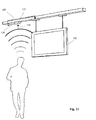
- the use of another terminal in the form of an infrared receiver 108 with a display 110 is shown in Fig.10.
- the display 110 (or a suitable Monitor) is used for playback of text and image information that has a high Require storage space and require a high transfer rate.
- a Transmission over the data line 112 of the busbar system is therefore not meaningful.
- the actual data is therefore from an infrared transmitter 116, which a memory 118 is coupled to the infrared receiver 108 of the display 110 transmitted, wherein the control is carried out via the data line 112 of the busbar.
- the information may also be contained in a memory included in the display 120 is integrated. This case is shown in FIG. 11.
- a sensor 122 takes Environment information, e.g. the noise level. This is indicated by an arrow 124 shown.
- the information is passed on to the central control unit. This is shown by an arrow 126.
- the control unit in turn initiates commands to Adjust the volume to the display 120. This is indicated by an arrow 128 shown.
- the brightness can be regulated by means of a control Brightness sensor can be adjusted.
- the system of Figure 11 is particularly well suited for use as a billboard for information texts, departure times at the airport terminal, but also for advertising recordings. It can work together with the display Presence and counting systems are used, which provide information about the number of Delivered persons. This is particularly interesting for the advertising industry.
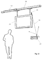
- Fig.12 also a display 130 is shown.
- the data is using an external video transmitter 132 to a receiver 136.
- multiple displays can Receive video information.
- control commands from the central control unit can via the busbar 138 in addition to the power supply and a selection and Controlling the displays done. This is shown by an arrow 140.
- the control of the displays may be based on information provided by Sensors are recorded.
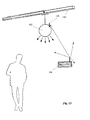
- Fig.13 an application is shown in which a public address system 142 to the Busbar 144 is connected.
- the sound system receives in the shown Representation information by means of an infrared receiver 146 of the data from a Infrared transmitter 148 receives.
- Volume, type and extent of radiated Audio information can again be controlled by the central control unit. In conjunction with a localization system as described with reference to FIG was, this can be a locally limited exclamation of the person sought.
- the selected sound system 142 automatically to the Radio channel switched the exclamation, while the rest of the system is not affected is.
- the volume of the sound system can also vary depending on the signals a noise level sensor or a presence sensor are set.
- the applications described above require terminals that are in one Busbar system can be used.
- the terminals can communicate with each other combined and changed. Add or remove devices can be made by the layman.
- Such a terminal is a Signal light. This is shown in FIG. 14.
- the signal light 150 receives its data from the data line of the bus bar 152, which implements it (without feedback). This is shown by an arrow 154.
- a luminous surface 156 which consists of a variety is composed of light-emitting diodes, it may vary depending on the data received any color will light up or blink.
- a suitable symbol are formed, such as an arrow, in the appropriate direction indicates which the instructed visitor should follow. By the combination of arrow and Number, letter or color, which light up alternately, can also be several Persons are directed.
- This form of the Visitor guidance comes from a prepared database maintained by staff at the Reception or by the visitor himself to be activated at a computer terminal by simply the desired destination is selected. On the monitor is then the letter or the Number to be followed to reach the selected destination.
- Analogous to a personal guidance module on a visual basis is also a Wegleitmodul or passenger orientation module provided on an acoustic basis. This is special suitable for the blind and visually impaired.
- a device is 160 shown.
- the device 160 consists of the combination of a distance or Motion detector 162 with a speaker 166.
- the device is located on the busbar 168th If a person or a movement is registered, sounds softly but for the Short range loud enough a brief information about the location.
- the device is also in Shopfitting applicable. Customers are then targeted to the products in the location Near field pointed. Together with a sensor, for example a distance detector, can also highlight lighting on appropriate goods and shelves to be activated.
- the safety module is connectable to the ballast or integrated into the ballast. He exists in essential from a fuse. With the installation of a safety module should be prevented that in case of defects in a terminal contact between the Power line of the data line is made. The data line can then be virtually free be designed accessible and needs due to the low flowing currents should not be secured against accidental contact by the user.
- the security module is designed as an adapter, which by a simple Plug connection can be connected.
Landscapes
- Engineering & Computer Science (AREA)
- General Engineering & Computer Science (AREA)
- Computer Networks & Wireless Communication (AREA)
- Circuit Arrangement For Electric Light Sources In General (AREA)
- Cable Transmission Systems, Equalization Of Radio And Reduction Of Echo (AREA)
- Selective Calling Equipment (AREA)
- Train Traffic Observation, Control, And Security (AREA)
- Machines For Laying And Maintaining Railways (AREA)
- Arrangements For Transmission Of Measured Signals (AREA)
- Connections Arranged To Contact A Plurality Of Conductors (AREA)
Abstract
Description
Die Erfindung betrifft ein Stromschienensystem mit einer Datenleitung, enthaltend ein oder mehrere Endgeräte, die an beliebigen Positionen in dem Stromschienensystem flexibel lösbar anschließbar sind, wobei ein gemeinsames zentrales Steuersystem vorgesehen ist, und wenigstens eines der Endgeräte ein Sensor oder ein Empfänger ist, mit welchem Signale aufnehmbar und über die Datenleitung an das zentrale Steuerungssystem leitbar sind.The invention relates to a busbar system with a data line, comprising a or multiple terminals at any location in the busbar system are flexibly detachably connectable, with a common central control system is provided, and at least one of the terminals is a sensor or a receiver, with which signals can be received and via the data line to the central Control system are conductive.
Bei der Gebäudetechnik und insbesondere bei der Beleuchtung von Gebäuden, oder Teilen von Gebäuden werden häufig Leuchten mit einstellbaren Parametern eingesetzt. Zu diesen einstellbaren Parametern gehört die Auswahl von Leuchten, die eingeschaltet werden sollen und die gewünschte Helligkeit, mit welcher die Leuchten strahlen. Üblicherweise werden die Leuchten mittels Schaltern zum Beispiel an einer Tür betätigt, die auch als Dimmer ausgestaltet sein können. Mit diesen Dimmern kann die Helligkeit der Leuchten eingestellt werden. In building technology and in particular in the lighting of buildings, or Parts of buildings are often used lights with adjustable parameters. These adjustable parameters include the selection of lights that are on and the desired brightness with which the lights shine. Usually, the lights are actuated by means of switches, for example on a door, which can also be configured as a dimmer. With these dimmers can the brightness the lights are set.
Es gibt weiterhin Stromschienensysteme, die es ermöglichen Leuchten flexibel durch einen Laien in beliebiger Zahl und Lage an gewünschten Positionen anzubringen. Die Stromschiene besteht aus einem meist U-förmigen Metallprofil, welches in oder an der Decke eines Raumes fest angebracht wird. Innerhalb der Stromschiene sind isolierte Leiterbahnen vorgesehen. Jede Leuchte ist mit einem Adapter versehen, der an dem Stromschienensystem befestigt wird und mittels eingebauter Kontakte mit der Stromleitung verbunden wird. Solche Stromschienensysteme haben den Vorteil, daß die Position der Leuchten auch vom Laien eingestellt werden können. Weiterhin haben die Stromschienensysteme den Vorteil, daß sie in neuen Gebäuden bereits verlegt werden können, auch wenn deren Nutzung und entsprechend die genaue Anzahl, Art und Lage der verwendeten Leuchten noch nicht feststeht. Bei derartigen Stromschienensystemen können die Leuchten jedoch nicht einzeln angesteuert werden. Es ist daher erforderlich, die Leuchten mit Informationen über den gewünschten Betriebszustand zu versorgen.There are also busbar systems that allow luminaires to be flexibly powered To lay a layman in any number and position at desired positions. The Busbar consists of a mostly U-shaped metal profile, which in or on the Ceiling of a room is firmly attached. Inside the busbar are insulated Conductors provided. Each luminaire is provided with an adapter attached to the Busbar system is attached and by means of built-in contacts with the Power line is connected. Such busbar systems have the advantage that the Position of the lights can also be adjusted by the layman. Furthermore, the Busbar systems have the advantage that they are already installed in new buildings can, even if their use and according to the exact number, type and location the lamps used is not yet known. In such busbar systems However, the lights can not be controlled individually. It is therefore necessary to provide the lights with information about the desired operating state.
Die Übertragung sämtlicher Informationen mittels Funk- oder Infrarotsendern und Empfängern zu diesem Zweck ist zwar prinzipiell möglich, jedoch störanfällig. Das Verfahren produziert den sogenannten Elektrosmog, der Störungen anderer Geräte bewirken kann. Auch ist die Verwendung der erforderlichen Sender und Empfänger kostenintensiv. Bei Infrarotübertragung können andere Systeme, die sich ebenfalls im Raum befinden gestört werden.The transmission of all information by means of radio or infrared transmitters and Although receivers for this purpose are in principle possible, but prone to failure. The Process produces the so-called electrosmog, the interference of other devices can cause. Also, the use of the required sender and receiver expensive. In infrared transmission, other systems that are also in the Room are disturbed.
Die Informationsübertragung über fest installierte Kabel kombiniert mit einer Stromversorgung über Kabelkanäle ist ebenfalls bekannt. Kabelkanäle sind fest installierte Kunststoffrohre oder -profile, in denen eine Vielzahl von Stromkabeln, Datenleitungen und anderen Kabeln lose gerührt werden kann. An dem Kunststoffrohr sind fest integrierte Anschlüsse vorgesehen, an denen die so verlegten Kabel angezapft und Energie oder Informationen über eine geeignete Schnittstelle entnommen werden können. Die Anschlüsse liegen dabei fest installiert an vorgegebenen Punkten des Kabelkanals. Zusätzliche Anschlüsse können nur über einen Fachmann mit vergleichsweise großem Aufwand installiert werden.The transmission of information via permanently installed cables combined with a Power supply via cable channels is also known. Cable ducts are solid installed plastic pipes or profiles, in which a variety of power cables, Data lines and other cables can be stirred loosely. On the plastic pipe There are permanently integrated connections on which the cables laid in this way are tapped and energy or information can be obtained through a suitable interface can. The connections are permanently installed at predetermined points of the Cable channel. Additional connections can only be made through a specialist be installed comparatively large effort.
Es ist weiterhin unter der Bezeichnung EIB (European Installation Bus) ein System mit einer Stromschiene und einer Datenleitung bekannt. Das System ist u.a. beschrieben in der Druckschrift "Tageslichtabhängige Beleuchtungssysteme auf der Basis von Installationsbussen" von P.T. Knoop, Fortschritt-Ber. VDI Reihe 6 Nr. 396 1998. Jede angeschlossene Leuchte ist bei diesem System über einen Knoten mit der Stromschiene und der Datenleitung verbunden. Der Knoten weist eine Datenverarbeitungseinheit auf. Die Knoten sind zusammen mit einem Informationsgenerator und einem Übersetzer in einem Aktor vorgesehen, der fest mit der Stromschiene verbunden ist. Jeder an das System angeschlossene Knoten ist dabei bezüglich der Kommunikation der angeschlossenen Geräte gleichberechtigt. Jedes angeschlossene Gerät ist Sender und Empfänger von Informationen, die über ein BUS-System kommuniziert werden. Eine zentrale Steuereinheit ist nicht vorgesehen. Das System eignet sich daher für quasi beliebig große Anwendungen wie die Verwaltung komplexer Gebäudetechnik für große Gebäude. Das System ist aber für viele einfachere Anwendungen zu teuer und aufwendig.It is also under the name of EIB (European Installation Bus) a system with a power rail and a data line known. The system is i.a. described in the publication "Daylight Dependent Lighting Systems Based on Installation Buses "by P.T. Knoop, Progress-Ber.VDI Series 6 No. 396 1998. Each connected light is in this system via a node with the power rail and the data line connected. The node has a data processing unit. The nodes are together with an information generator and a translator in an actuator provided which is fixedly connected to the busbar. Everyone at the System connected node is doing with respect to the communication of connected devices equally. Each connected device is transmitter and Receiver of information communicated via a BUS system. A central control unit is not provided. The system is therefore suitable for quasi arbitrarily large applications such as the management of complex building services for large Building. However, the system is too expensive for many simpler applications consuming.
Ein weiteres solches System ist aus der der DE 299 06 910 U1 bekannt. Dort wird eine Hängevorrichtung für elektrisch zu kontaktierende Gegenstände offenbart. Auch dabei handelt es sich um ein bidirektionales Zweidraht-Bussystem, d.h. um ein System, bei welchem die angeschlossenen Endgeräte über eine eigene Intelligenz verfügen. Das beschriebene System ist mit erheblichen Kosten verbunden, da jedes Endgerät mit einem Mikroprozessor ausgestattet werden muß.Another such system is known from DE 299 06 910 U1. There will be one Hanging device for objects to be electrically contacted disclosed. Also here it is a bidirectional two-wire bus system, i. to a system, at which the connected terminals have their own intelligence. The described system is associated with considerable costs, since each terminal with a Microprocessor must be equipped.
Aus der DE 38 12 465 C2 ist es weiterhin bekannt, einfache für die Beleuchtungstechnik vorgesehene Stromschienen mit Datenleitungen zu kombinieren. Das System weist eine zentrale Steuereinheit auf, welche die Steuerung des Systems übernimmt (Master-Slave-System). Die angeschlossenen Leuchten können über ein einfaches Vorschaltgerät und einen Adapter mit der Stromschiene verbunden werden. Über die Datenleitung können Steuerdaten in Richtung auf die Leuchten kommuniziert werden. Dadurch wird die zentrale Einstellung zum Beispiel der Helligkeit erreicht.From DE 38 12 465 C2, it is also known, simple for lighting technology intended busbars to be combined with data lines. The system has a Central control unit, which takes over the control of the system (master-slave system). The connected lights can be controlled via a simple ballast and an adapter to be connected to the power rail. Over the data line can Control data in the direction of the lights are communicated. This will be the central setting for example the brightness reached.
Bei dem bekannten Stromschienensystem mit Datenleitung fließen die Daten in Form von Steuerbefehlen vom zentralen Steuerrechner zu den angeschlossenen Leuchten. Eine Veränderung des Betriebszustands kann daher nur durch ein Programm oder eine Eingabe am Steuerrechner erreicht werden. In the known busbar system with data line, the data flows in the form of control commands from the central control computer to the connected lights. A Changing the operating state can therefore only by a program or a Input to the control computer can be achieved.
Es ist Aufgabe der Erfindung, ein Stromschienensystem zu schaffen, bei dem angeschlossene Endgeräte in Abhängigkeit von den Umgebungsbedingungen steuerbar sind und welches kostengünstig realisierbar ist.It is an object of the invention to provide a busbar system, in which Connected terminals controllable depending on the environmental conditions are and which is inexpensive to implement.
Erfindungsgemäß wird die Aufgabe dadurch gelöst, daß die Endgeräte individuell addressierbar ohne eigene Steuerfunktionen sind und und eine Datenübertragung nach dem Master-Slave-Prinzip ausschließlich zwischen einem Endgerät und dem zentralen Steuersystem erfolgt. Durch die Verwendung von Sensoren oder Empfängern fließen Informationen auch in der entgegengesetzten Richtung zum Steuerrechner. Der Steuerrechner kann die vom Sensor oder Empfänger gelieferten Informationen aufnehmen, zentral verarbeiten und die Resultate zur Steuerung weiterer angeschlossener Endgeräte vorsehen. Durch die Verwendung eines gemeinsamen Steuerrechners können die Endgeräte entsprechend kostengünstig ausgeführt werden. Die Endgeräte brauchen keine eigenen Datenverarbeitungseinheiten. Die ohnehin vorhandene Infrastruktur für die Stromversorgung wird gleichzeitig für die Datenkommunikation nutzbar gemacht, wobei eine besonders hohe Flexibilität gewährleistet wird, da die Endgeräte vom Laien ohne besonderen Aufwand installiert werden können. Dies macht die Verwendung in solchen Fällen besonders attraktiv, in denen die Nutzungsart häufig wechselt und die Installationen entsprechend jeweils an unterschiedlichen Stellen vorgesehen sind. Für die Kommunikation eignen sich diverse Standards, zum Beispiel der Kommunikations-Standard DALI (Digital Addressable Lighting Interface).According to the invention the object is achieved in that the terminals individually are addressable without own control functions and and a data transfer after the master-slave principle exclusively between a terminal and the central Control system takes place. Flow through the use of sensors or receivers Information also in the opposite direction to the control computer. Of the Control computer can be the information provided by the sensor or receiver record, centrally process and the results to control other connected Provide terminals. By using a common control computer can the terminals are carried out according to cost. The terminals need no own data processing units. The already existing infrastructure for the Power supply is made available simultaneously for data communication, wherein a particularly high level of flexibility is guaranteed, since the devices from the layman without special effort can be installed. This makes use in such Particularly attractive cases in which the type of use changes frequently and the Installations are each provided at different locations. For the Communication is suitable for various standards, for example the communication standard DALI (Digital Addressable Lighting Interface).
Als Endgeräte sind zunächst einmal Leuchten besonders geeignet. Es können auch andere Verbraucher, wie Monitore, akustische Signalgeber, digitale und analoge Aufnahme- und Abspielgeräte für Musik, gesprochene Texte oder sonstige Geräusche vorgesehen sein. Jedes Mal, wenn der Sensor ein vorgegebenes Signal empfängt wird das Endgerät in Betrieb genommen, der Betrieb eingestellt oder verändert. Wenn eines der Endgeräte ein Monitor ist, können Videosequenzen oder Bilder sichtbar werden, wenn der Sensor ein vorgegebenes Signal empfängt. As terminals first of all lights are particularly suitable. It can too other consumers, such as monitors, sounders, digital and analogue Recording and playback devices for music, spoken texts or other sounds be provided. Each time the sensor receives a given signal, the Terminal set in operation, the operation set or changed. If one of the If a terminal is a monitor, video sequences or images may become visible if the sensor receives a predetermined signal.
Das Endgerät kann auch ein Anzeigesystem sein, welches in Abhängigkeit von einem vorgegebenen Sensorsignal einen Richtungshinweis abgibt. Ein solches Anzeigesystem kann ein beleuchter oder leuchtender Pfeil sein, oder auch ein Display mit verschiedenen Anzeigemöglichkeiten. Damit kann ein Personenleitsystem aufgebaut werden.The terminal may also be a display system which depends on a given sensor signal gives a direction indication. Such a display system can be a lit or glowing arrow, or even a display with different Display options. This can be used to set up a person guidance system.
Es können weiterhin Mittel zur Protokollierung von Sensorsignalen oder auf den
Sensorsignalen basierenden Informationen vorgesehen sein. Dann kann das System zur
Überwachung und nachträglichen Auswertung von Vorgängen verwendet werden.
Hierfür sind auch Mittel zur Erzeugung eines Alarm- oder Notrufsignals besonders
geeignet.Furthermore, means for logging sensor signals or information based on the sensor signals can be provided. Then the system can be used for monitoring and subsequent evaluation of operations.
For this purpose, means for generating an alarm or emergency call signal are particularly suitable.
Die angeschlossenen Sensoren können akustische und/oder optische Signale, zum Beispiel in Form von Bildern, Bildfolgen oder Videosequenzen aufnehmen. Es können auch Zählmittel vorgesehen sein. Dann können Vorgänge statistisch oder anders erfasst werden und liefern so zusätzliche Informationen. Die Sensoren können als Anwesenheitssensoren ausgebildet sein, die eine Betätigung übriger Endgeräte auslöst wenn Personen anwesend sind und Mittel zum Abschalten der Endgeräte, wenn die Personen sich entfernt haben. Dies ist besonders zum Einsparen von Energie geeignet.The connected sensors can be acoustic and / or optical signals, for Take an example in the form of pictures, picture sequences or video sequences. It can Also be provided counting means. Then events can be recorded statistically or otherwise and thus provide additional information. The sensors can as Presence sensors may be formed, which triggers an actuation of remaining terminals if persons are present and means of switching off the terminals when the People have moved away. This is especially suitable for saving energy.
Es können vom zentralen Steuerrechner ansteuerbare mechanische Einstellmittel vorgesehen sein, mittels derer die Lage und Ausrichtung der Endgeräte einstellbar ist. Es können weiterhin vom zentralen Steuerrechner ansteuerbare Mittel zur Veränderung der Farbe von angeschlossenen Leuchten vorgesehen sein. Es können auch Leuchten mit optischen Mitteln vorgesehen sein, deren Eigenschaften mittels Einstellung am zentralen Steuerrechner veränderbar sind. Dann können auch die Eigenschaften schlecht erreichbarer Leuchten optimal eingestellt werden und komplette Szenarien ohne großen Aufwand verändert und programmiert werden.It can be controlled by the central control computer mechanical adjustment be provided by means of which the position and orientation of the terminals is adjustable. It can continue to be controlled by the central control computer means for changing the Be provided color of connected lights. It can also be used with lights be provided optical means whose properties by means of adjustment at the central Control computer are changeable. Then the properties can be bad too achievable lights are optimally adjusted and complete scenarios without large Effort can be changed and programmed.
Bei größeren Anwendungen kann die Anordnung als kleinerer Baustein an ein BUS-System ankoppelbar sein. Hierfür kann eine geeignete Schnittstelle oder ein Koppler vorgesehen sein. Dann können auch große Zahlen von Endgeräten in komplexen Anwendungen eingesetzt werden. Statt eines Sensors kann auch ein Empfänger vorgesehen sein, der Steuersignale eines Senders zur Steuerung weiterer Endgeräte erhält. Dieser Empfänger kann Infrarot-Signale oder Funksignale oder dergleichen erhalten. Dann werden die Vorgänge durch einen Befehl ausgelöst.For larger applications, the device may be a smaller device to a BUS system be coupled. For this purpose, a suitable interface or a coupler be provided. Then you can get large numbers of terminals in complex Applications are used. Instead of a sensor can also be a receiver be provided, the control signals of a transmitter for controlling other terminals receives. This receiver can be infrared signals or radio signals or the like receive. Then the operations are triggered by a command.
Ein solches Stromschienensystem kann zur Beleuchtung und Inszenierung von Schaufenstern und Bühnen, als Tourguide und Beleuchtung in Museen und Ausstellungsräumen, zur Lokalisierung von Personen oder Gegenständen in einem Gebäude oder als Leitsystem in Gebäuden mit Publikumsverkehr verwendet werden.Such a busbar system can be used for lighting and staging Shop windows and stages, as a tour guide and lighting in museums and Exhibition rooms, for the localization of persons or objects in one Building or used as a control system in buildings with public traffic.
Es sind alle Sensoren geeignet, die relevante physikalische Größen erfassen. Dazu gehören besonders Temperatur, Luftfeuchtigkeit, Luftqualität, Rauchmelder, Bewegungsmelder, Helligkeit, im sichtbaren und UV-Bereich, Geräuschpegel, Zug- und Druck etc. Letztere können für die Erkennung von Einbruch und Vandalismus verwendet werden.All sensors that detect relevant physical quantities are suitable. To include temperature, humidity, air quality, smoke detectors, Motion detector, brightness, in the visible and UV range, noise level, tension and Pressure etc. The latter can be used for detection of burglary and vandalism become.
Ausgestaltungen der Erfindung sind Gegenstand der Unteransprüche. Ein Ausführungsbeispiel ist nachstehend unter Bezugnahme auf die beigefügten Zeichnungen näher erläutert.Embodiments of the invention are the subject of the dependent claims. One Embodiment is described below with reference to the accompanying drawings explained in more detail.
- Fig.1a1a
- zeigt schematisch eine Stromschiene mit angeschlossener zentralen Steuereinheit.schematically shows a busbar with connected central Control unit.
- Fig.1b1b shows
- zeigt die Stromschiene aus Fig.1a im Querschnittshows the busbar of Figure 1a in cross section
- Fig.2Fig.2
- zeigt schematisch eine Stromschiene, die über einen Koppler mit einem Datenbus verbunden ist.schematically shows a busbar, via a coupler with a Data bus is connected.
- Fig.3Figure 3
- zeigt eine Mehrzahl von Stromschienen, die jeweils über einen Koppler mit einem Datenbus verbunden sind.shows a plurality of bus bars, each via a coupler with connected to a data bus.
- Fig.4Figure 4
- zeigt eine Stromschiene mit einem Beleuchtungssystem und einem Infrarot-Empfänger shows a bus bar with a lighting system and an infrared receiver
- Fig.5Figure 5
- zeigt eine Stromschiene mit einem Beleuchtungssystem und einem Tageslichtsensorshows a bus bar with a lighting system and a Daylight sensor
- Fig.6Figure 6
- zeigt Beleuchtungssystem mit Stromschienen in Form eines einfachen Leitsystemsshows lighting system with busbars in the form of a simple control system
- Fig.7Figure 7
- veranschaulicht die Verwendung eines Stromschienensystems mit einem Infrarotsender in einem Museumillustrates the use of a busbar system with a Infrared transmitter in a museum
- Fig.8Figure 8
- veranschaulicht die Verwendung eines Stromschienensystems in einem Museum, bei dem Informationen bereits im Empfangsgerät des Anwenders hinterlegt sind.illustrates the use of a bus bar system in one Museum, where information already in the receiver of the user are deposited.
- Fig.9Figure 9
- zeigt den Einsatz eines Stromschienensystems zur Lokalisierung von Personen.shows the use of a busbar system for the localization of People.
- Fig. 10Fig. 10
- zeigt ein Stromschienensystem mit einem Empfänger, welcher Informationen zur Darstellung auf einem Display empfängt.shows a busbar system with a receiver, which Receive information about presentation on a display.
- Fig.11Figure 11
- zeigt ein Stromschienensystem mit einem Display, dessen Betriebseinstellungen in Abhängigkeit von einem Sensor gesteuert werden.shows a busbar system with a display whose Operating settings are controlled in dependence on a sensor.
- Fig.12Figure 12
- zeigt ein Stromschienensystem, bei welchem ein Display Informationen aus einem Sender erhältshows a busbar system, in which a display information a station receives
- Fig.13Figure 13
- zeigt ein Stromschienensystem, an welchem ein Empfänger mit einem Lautsprecher angeschlossen ist, der Audioinformationen wiedergibt.shows a busbar system to which a receiver with a Speaker that plays audio information.
- Fig.14Figure 14
- zeigt eine an einer Stromschiene angeschlossene Signalleuchte.shows a signal light connected to a power rail.
- Fig.15Figure 15
- zeigt ein Personenleitmodul auf akustischer Basisshows a Personenleitmodul on an acoustic basis
In Fig.1a ist schematisch ein Teil einer Stromschiene 10 gezeigt. Eine solche
Stromschiene ist bereits bekannt. Die Stromschiene 10 ist in Fig.1b nochmals im
Querschnitt gezeigt. Die Stromschiene 10 hat einen im wesentlichen U-förmigen
Querschnitt, mit nach unten hin geöffnetem U. In das U-förmige Profil können beliebige
Anschlußteile mittels eines geeigneten, nicht dargestellten, Adapters befestigt werden.
Der Kontakt mit der Stromquelle erfolgt über Kabel 17, 19, 21 und 23. Die
Stromschienen sind im prinzip bekannt, z.B. aus der US 5,869,786 und brauchen daher
hier nicht weiter beschrieben werden. Die Stromschiene 10 ist weiterhin mit einer
Datenleitung 11 in Form von zwei Kupferkabeln 13 und 15 versehen. Die Daten können
hier in beiden Richtungen fließen. Es ist weiterhin eine Steuereinheit 12 vorgesehen
(Fig.1a). Die Steuereinheit 12 übernimmt die Steuerung und Regelung sämtlicher an die
Stromschiene angeschlossenen Endgeräte. Die Steuereinheit 12 kann auch als Adapter in
beliebiger Position der Stromschiene eingesetzt werden. Die in Fig. dargestellte
Situation kann ohne aufwendige Bus-Systeme zur Datenübertragung arbeiten und ist
daher vergleichsweise kostengünstig. Aufgrund der begrenzten Zahl an Endgeräten ist sie
jedoch nur für kleinere Anwendungen geeignet.In Fig.1a a part of a
In Fig.2 ist zwischen der Stromschiene 10 und der Steuereinheit 12 ein Koppler 14
vorgesehen. Der Koppler 14 ermöglicht die Datenübertragung von der Stromschiene 10
auf ein Bussystem. Solche Bussysteme können EIB oder LON sein. Dadurch wird der
Anwendungsbereich vergrößert. Die Steuereinheit 12 führt hier umfangreiche
Funktionen auf der Basis des komplexen Bussystems aus.2, between the
Ein solches Bussystem kann zur Verknüpfung einer Vielzahl von Stromschienen dienen.
Dies ist in Fig.3 dargestellt. Hier sind fünf Stromschienen 16, 18, 20, 22 und 24 über
jeweils eigene Koppler 28, 30, 32, 34 und 36 und den Datenbus mit der zentralen
Steuereinheit 26 verbunden. Es ist immer nur ein Koppler für eine Vielzahl von
Endgeräte vorgesehen. Such a bus system can serve to link a plurality of busbars.
This is shown in Fig.3. Here are five
Je nach angeschlossenem Endgerät sind unterschiedliche Verwendungen der
beschriebenen Systeme möglich. In Fig. 4 ist ein einfaches Beleuchtungssystem 38
gezeigt. Eine Leuchte 40 ist beweglich in einer Halterung 42 angeordnet. Die Leuchte ist
mit einem Vorschaltgerät 44 versehen. Die Beleuchtungsanordnung ist mit einem
Adapter 46 an der Stromschiene festgeklemmt, welcher die Verbindung mit der
Stromleitung und der Datenleitung herstellt. Das Vorschaltgerät 44 dient zur Aufnahme
von Datenverarbeitungsmitteln zur Einstellung des Betriebszustands der Leuchte 40. Der
Betriebszustand wird dabei insbesondere durch Dimmen, Schalten, Drehen und
Schwenken der Leuchte eingestellt. Für komplexere Anwendungen in der
Beleuchtungstechnik können auch optische Mittel wie Farbfilter, Linsen oder Spiegel
eingesetzt werden. Dann kann der Betriebszustand durch unterschiedliche Fokussierung,
Farben etc. beeinflusst werden. Die hierfür erforderlichen Daten erhält das
Beleuchtungssystem 38 von einem nicht dargestellten zentralen Steuerrechner. Dies ist
durch einen Pfeil 48 dargestellt.Depending on the connected terminal are different uses of
described systems possible. In Fig. 4 is a simple illumination system 38th
shown. A
Zur Einstellung des Betriebszustands des Beleuchtungssystems ist ein Infrarot-Empfänger
50 in der Stromschiene vorgesehen. Der Infrarot-Empfänger 50 empfängt
Daten von einem Infrarot-Sender 52, der vom Anwender 54 nach Art einer
Fernbedienung betätigt wird. Statt einer Datenübertragung mittels Infrarot-Signalen kann
auch eine Datenübertragung per Funk oder einem Kabel erfolgen. Die aktuellen Werte
des Schienenabschnitts für den Betriebszustands werden auf einem Display der
Fernbedienung 52 angezeigt. Durch Eingabe neuer Daten kann dann der Betriebszustand
am Beleuchtungssystem 38 verändert werden. Hierfür werden die Infrarot-Signale
zunächst an den Empfänger 50 gesendet. Dies ist durch einen Pfeil 56 dargestellt. Der
Empfänger 50 wandelt die Infrarot-Signale in einen Datenstrom und gibt diese an den
zentralen Steuerrechner weiter. Dies ist durch einen Pfeil 58 dargestellt. Mittels der
Fernbedienung sind auch schlecht erreichbare Beleuchtungssysteme auf Bühnen oder
dergleichen gut einstellbar. Weitere Leuchten können durch den gleichen Empfänger
angesteuert werden. Solche komplexere Beleuchtungssysteme treten zum Beispiel in
Schaufenstern oder Bühnen auf. Zur mechanischen Einstellung der Leuchten sind
Motoren in Form von Servo- oder Schrittmotoren vorgesehen, die die Lage der Leuchten,
z.B. den Drehwinkel einstellen können. To adjust the operating state of the lighting system is an
Statt eines ansteuerbaren Empfängers wird im Ausführungsbeispiel von Fig.5 ein
Tageslichtsensor 60 eingesetzt. Das Tageslicht, repräsentiert durch einen Pfeil 62, wird
vom Sensor 60 detektiert und die zugehörige Meßgröße an den zentralen Steuerrechner
weitergegeben. Dies ist durch einen Pfeil 64 dargestellt. In größeren Räumen werden
mehrere solcher Sensoren angeordnet, die ebenfalls Meßdaten an den Steuerrechner
weitergeben. Im zentralen Steuerrechner werden die Daten ausgewertet und Anzahl der
anzuschaltenden Leuchten, ihre Lage und ihr Dimmgrad für die angeschlossenen
Beleuchtungssysteme ermittelt. Die Steuersignale werden von der zentralen Steuereinheit
über die in der Stromschiene integrierte Datenleitung an das Beleuchtungssystem 66
weitergegeben. Dies ist durch den Pfeil 68 dargestellt. Durch den Einsatz von Sensoren
lässt sich ein intelligentes Gebäudemanagement realisieren, das Energieeinsparungen im
Beleuchtungsbereich erreicht. Statt eines Tageslichtsensors können auch andere
Sensoren eingesetzt werden, deren Meßwerte neben Beleuchtungssystemen auch andere
Systeme, wie zum Beispiel Jalousien beeinflussen. Hierzu zählen Geräuschpegelmesser,
UV-Lichtsensoren, Distanzmesser, Anwesenheitssensoren, Bewegungsmelder oder
Fenster-/Türkontakte.Instead of a controllable receiver is in the embodiment of Figure 5 a
In Fig.6 ist ein Beleuchtungssystem in Form eines einfachen Leitsystems dargestellt.
Nach Aktivierung des Leitsystems mittels eines Sensors oder eines Empfängers werden
ausgewählte Leuchten 70 aktiviert. Andere Leuchten 74, die nicht auf dem Weg liegen
bleiben abgeschaltet. Der Ortsunkundige 72 braucht dann nur noch den Leuchten
nacheinander folgen um an ein Ziel zu gelangen. Dabei können die Leuchten in
Verbindung mit Anwesenheitssensoren oder Bewegungsmeldern nacheinander aktiviert
werden um den Weg zu weisen. Sie können auch gleichzeitig aktiviert werden. Die
Leuchten können auch als Pfeile ausgestaltet sein, oder Weghinweise auf den Boden
projezieren.FIG. 6 shows a lighting system in the form of a simple control system.
After activation of the control system by means of a sensor or a receiver
selected
In Fig.7 ist die Verwendung eines Stromschienensystems 76 in einem Museum oder
einer Ausstellung gezeigt. Ein lokaler Funksender 78 verteilt die für alle Exponate 80
bereitgestellten Audioinformationen auf je einem Kanal. Dies ist durch Pfeile 82
dargestellt. Im Bereich der Exponate 80 befindet sich jeweils ein Empfangsgerät 84 an
der Stromschiene. Das Empfangsgerät 84 empfängt die Signale 82 auf dem Kanal des zu
dem Empfangsgerät 84 zugehörigen Exponats 80. Über die Datenleitung der
Stromschiene 76 wird der benötigte Funkkanal ausgewählt und als Infrarot-Tonsignal an
alle Kopfhörer 86, die sich in diesem Bereich befinden, versendet. Statt einer
Infrarotübertragung kann auch eine Funkübertragung eingesetzt werden. Dies ist durch
einen Pfeil 88 dargestellt. Durch die Verwendung des Funksenders brauchen keine
großen Datenmengen an den Empfänger übertragen werden, sondern nur die Information
über den Funkkanal. Statt eines Kopfhörers kann auch ein Lautsprecher eingesetzt
werden, der aktiviert wird, wenn sich eine Person vor einem Exponat befindet.In Fig.7, the use of a
In Fig. 8 ist eine andere Lösung für die Informationsvermittlung in einem Museum
dargestellt. Bei dieser Lösung sind die Informationen, d.h. die Audioinformationen zu
verschiedenen Exponaten 90 im Museum, bereits vollständig im Empfangsgerät 92
hinterlegt. Der gezielte, lokal gebundene Abruf der Informationen erfolgt über einen
Infrarotsender 94 an der Stromschiene. Auch hier kann eine Funkübertragung statt
Infrarotübertragung erfolgen. Die Auswahl der Information ist durch die
Datenübertragung der Stromschiene festgelegt. Dieses Prinzip lässt sich auch sehr gut bei
einem Leitsystem anwenden.In Fig. 8 is another solution for the information exchange in a museum
shown. In this solution, the information, i. the audio information too
In Fig.9 ist an der Stromschiene ein Infrarot-Sender 96 auf der Schulter einer Person 98
befestigt. Der Sender 98 sendet fortlaufend eine personenspezifische Codierung aus, die
an signifikanten Orten in einem komplexen Gebäude von Infrarot-Empfängern 100
erkannt wird. Dies ist durch einen Pfeil 102 dargestellt. Die Daten werden über die
Stromschiene 106 an die zentrale Steuereinheit weitergeleitet. Dies ist durch den Pfeil
104 dargestellt. Die Daten umfassen Informationen über den aktuellen Standort einer
Person, die von einer Zentrale erfasst und ggf. protokolliert werden können. Die Zentrale
ist somit fortlaufend informiert über die Position und Aufenthaltsdauern aller
interessierenden Personen im Haus. Auch Gegenstände, wie Akten oder dergleichen
können derartig lokalisiert werden. Das Lokalisierungssystem ist besonders gut geeignet
für die Verwendung in Krankenhäusern, Seniorenheimen etc., in denen Ärzte oder
Krankenschwestern schnell auffindbar sein müssen.In Figure 9 is on the power rail, an
Die Verwendung eines weiteren Endgerätes in Form eines Infrarot-Empfängers 108 mit
einem Display 110 ist in Fig.10 dargestellt. Das Display 110 (oder ein geeigneter
Monitor) dient der Wiedergabe von Text- und Bildinformationen, die einen hohen
Speicherplatzbedarf haben und eine hohe Übertragungsrate erforderlich machen. Eine
Übertragung über die Datenleitung 112 des Stromschienensystems ist daher nicht
sinnvoll. Die eigentlichen Daten werden daher von einem Infrarot-Sender 116, der an
einen Speicher 118 gekoppelt ist, auf den Infrarot-Empfänger 108 des Displays 110
übertragen, wobei die Steuerung über die Datenleitung 112 der Stromschiene erfolgt.
Diese umfasst die Auswahl, Modifikation und Einstellung des Ablaufs der Bildfolgen.
Dazu gehören die Start und Ende, Lautstärke, Helligkeit, Länge der Sequenzen und
dergleichen. Dies ist durch einen Pfeil 114 dargestellt. Auch werden die Einstellungen
aufgrund von Umgebungsinformationen vorgenommen, die über Sensoren (nicht
dargestellt) oder Empfänger erhalten werden.The use of another terminal in the form of an
Die Informationen können auch in einem Speicher enthalten sein, der in dem Display 120
integriert ist. Dieser Fall ist in Fig. 11 dargestellt. Ein Sensor 122 nimmt
Umgebungsinformationen, z.B. den Geräuspegel auf. Dies ist durch einen Pfeil 124
dargestellt. Die Informationen werden an die zentrale Steuereinheit weitergegeben. Dies
ist durch einen Pfeil 126 dargestellt. Die Steuereinheit wiederum leitet Befehle zur
Einstellung der Lautstärke an das Display 120 weiter. Dies ist durch einen Pfeil 128
dargestellt. Auf gleiche Weise kann die Helligkeit mittels einer Regelung über einen
Helligkeitssensor eingestellt werden. Das System aus Fig.11 eignet sich besonders gut
zum Einsatz als Hinweistafel für Hinweistexte, Abfahrtszeiten im Flughafenterminal,
aber auch für Werbeeinspielungen. Es können zusammen mit dem Display
Anwesenheits- und Zählsysteme eingesetzt werden, die Informationen über die Zahl der
erfassten Personen liefern. Dies ist insbesondere für die Werbewirtschaft interessant.The information may also be contained in a memory included in the
In Fig.12 ist ebenfalls ein Display 130 dargestellt. Hier werden jedoch die Daten mittels
eines externen Videosenders 132 auf einen Empfänger 136 übertragen. Dies ist durch
einen Pfeil 134 dargestellt. Bei dieser Lösung können mehrere Displays die
Videoinformationen empfangen. Durch Steuerbefehle aus der zentralen Steuereinheit
kann über die Stromschiene 138 neben der Stromversorgung auch eine Auswahl und
Steuerung der Displays erfolgen. Dies ist durch einen Pfeil 140 dargestellt. Auch hier
kann die Steuerung der Displays aufgrund von Informationen erfolgen, die mittels
Sensoren aufgenommen werden. In Fig.12 also a
In Fig.13 ist eine Anwendung dargestellt, bei der eine Beschallungsanlage 142 an die
Stromschiene 144 angeschlossen ist. Die Beschallungsanlage erhält in der gezeigten
Darstellung Informationen mittels eines Infrarotempfängers 146 der Daten von einem
Infrarotsender 148 erhält. Lautstärke, Art und Umfang der abgestrahlten
Audioinformationen können widerum von der zentralen Steuereinheit gesteuert werden.
In Verbindung mit einem Lokalisierungssystem, wie es anhand von Fig.9 beschrieben
wurde, kann damit ein lokal begrenzter Ausruf der gesuchten Person erfolgen. Dabei
wird über die datenleitung 144 das gewählte Beschallungsgerät 142 automatisch auf den
Funkkanals des Ausrufs umgeschaltet, während die übrige Anlage davon nicht betroffen
ist. Die Lautstärke der Beschallungsanlage kann auch in Abhängigkeit von den Signalen
eines Geräuschpegelsensors oder eines Anwesenheitssensors eingestellt werden.In Fig.13 an application is shown in which a
Die oben beschriebenen Anwendungen erfordern Endgeräte, die in einem Stromschienensystem eingesetzt werden können. Die Endgeräte können untereinander kombiniert und verändert werden. Das Hinzufügen oder Abmontieren von Endgeräten kann vom Laien vorgenommen werden.The applications described above require terminals that are in one Busbar system can be used. The terminals can communicate with each other combined and changed. Add or remove devices can be made by the layman.
Neben den beschriebenen Sensoren, Leuchten, Displays und Beschallungsanlagen sind
weitere Endgeräte an die Stromschiene anklemmbar. Ein solches Endgerät ist eine
Signalleuchte. Diese ist in Fig. 14 dargestellt. Die Signalleuchte 150 erhält ihre Daten
aus der Datenleitung der Stromschiene 152, die sie (ohne Rückmeldung) umsetzt. Dies
ist durch einen Pfeil 154 dargestellt. Als eine Leuchtfläche 156, die aus einer Vielzahl
von Leuchtdioden zusammengesetzt ist, kann sie je nach den empfangenen Daten in
einer beliebigen Farbe leuchten oder blinken. Ferner kann aus den Leuchtpunkten ein
geeignetes Symbol gebildet werden, etwa ein Pfeil, der in die entsprechende Richtung
zeigt, der der angewiesene Besucher folgen soll. Durch die Kombination von Pfeil und
Ziffer, Buchstabe oder Farbe, die abwechselnd aufleuchten, können auch mehrere
Personen gezielt gelenkt werden. Die notwendigen Daten, die diese Form der
Besucherlenkung stammen aus einer vorbereiteten Datenbank, die vom Personal an der
Rezeption oder vom Besucher selbst an einem Computerterminal aktiviert werden, indem
einfach das Wunschziel angewählt wird. Am Monitor wird dann der Buchstabe bzw.die
Ziffer angezeigt, der man folgen soll, um zum gewählten Ziel zu gelangen. In addition to the described sensors, lights, displays and public address systems are
further terminals can be connected to the busbar. Such a terminal is a
Signal light. This is shown in FIG. 14. The
Analog zu einem Personenleitmodul auf visueller Basis ist auch ein Personenleitmodul
oder Personenorientierungsmodul auf akustischer Basis vorgesehen. Dieses ist besonders
für Blinde und sehbehinderte Menschen geeignet. In Fig.15 ist ein solches Gerät 160
dargestellt. Das Gerät 160 besteht aus der Kombination eines Distanz- oder
Bewegungsmelders 162 mit einem Lautsprecher 166. An besonderen, u.U. auch speziell
gekennzeichneten Orten im Gebäude befindet sich das Gerät an der Stromschiene 168.
Sofern eine Person bzw. eine Bewegung registriert wird, ertönt leise aber für den
Nahbereich laut genug eine kurze Information zum Standort. Das Gerät ist auch im
Ladenbau anwendbar. Kunden werden dann gezielt ortsabhängig auf die Produkte im
Nahfeld hingewiesen. Zusammen mit einem Sensor, zum Beispiel einem Distanzmelder,
können auch hervorhebende Beleuchtungen auf entsprechende Waren und Regale
aktiviert werden.Analogous to a personal guidance module on a visual basis is also a Personenleitmodul
or passenger orientation module provided on an acoustic basis. This is special
suitable for the blind and visually impaired. In Fig. 15, such a device is 160
shown. The
Alle Endgeräte sind mit einem Sicherheitsbaustein versehen. Der Sicherheitsbaustein ist an das Vorschaltgerät anschließbar oder in das Vorschaltgerät integrierbar. Er besteht im wesentlichen aus einer Sicherung. Mit dem Einbau eines Sicherheitsbausteins soll verhindert werden, daß bei Defekten in einem Endgerät ein Kontakt zwischen der Stromleitung der Datenleitung hergestellt wird. Die Datenleitung kann dann quasi frei zugänglich ausgestaltet werden und braucht aufgrund der geringen fließenden Ströme nicht extra gegen unbeabsichtigtes Berühren durch den Anwender gesichert werden. Dabei ist der Sicherheitsbaustein als Adapter ausgebildet, der durch eine einfache Steckverbindung anschließbar ist.All terminals are provided with a security module. The safety module is connectable to the ballast or integrated into the ballast. He exists in essential from a fuse. With the installation of a safety module should be prevented that in case of defects in a terminal contact between the Power line of the data line is made. The data line can then be virtually free be designed accessible and needs due to the low flowing currents should not be secured against accidental contact by the user. In this case, the security module is designed as an adapter, which by a simple Plug connection can be connected.
Claims (25)
dadurch gekennzeichnet, daß
die Endgeräte individuell addressierbar ohne eigene Steuerfunktionen sind und und eine Datenübertragung nach dem Master-Slave-Prinzip ausschließlich zwischen einem Endgerät und dem zentralen Steuersystem erfolgt.Busbar system having a data line, comprising one or more terminals (50, 38) which are flexibly detachably connectable at arbitrary positions in the busbar system, wherein a common central control system is provided, and at least one of the terminals is a sensor (50) or a receiver with which signals can be received and can be conducted via the data line (48) to the central control system,
characterized in that
the terminals are individually addressable without their own control functions and and a data transfer according to the master-slave principle takes place exclusively between a terminal and the central control system.
Applications Claiming Priority (2)
| Application Number | Priority Date | Filing Date | Title |
|---|---|---|---|
| DE10212232 | 2002-03-19 | ||
| DE10212232A DE10212232A1 (en) | 2002-03-19 | 2002-03-19 | Busbar with data line |
Publications (3)
| Publication Number | Publication Date |
|---|---|
| EP1349437A2 true EP1349437A2 (en) | 2003-10-01 |
| EP1349437A3 EP1349437A3 (en) | 2004-11-10 |
| EP1349437B1 EP1349437B1 (en) | 2010-05-26 |
Family
ID=27797938
Family Applications (1)
| Application Number | Title | Priority Date | Filing Date |
|---|---|---|---|
| EP03090066A Expired - Lifetime EP1349437B1 (en) | 2002-03-19 | 2003-03-14 | Conductor rail system with control line |
Country Status (7)
| Country | Link |
|---|---|
| US (1) | US6933444B2 (en) |
| EP (1) | EP1349437B1 (en) |
| AT (1) | ATE469531T1 (en) |
| AU (1) | AU2003201014B2 (en) |
| CA (1) | CA2422399C (en) |
| DE (2) | DE10212232A1 (en) |
| ES (1) | ES2345609T3 (en) |
Cited By (6)
| Publication number | Priority date | Publication date | Assignee | Title |
|---|---|---|---|---|
| WO2008145204A1 (en) * | 2007-05-25 | 2008-12-04 | Cooper Crouse-Hinds Gmbh | Lighting fixture and rail module |
| EP2287978A1 (en) * | 2009-08-17 | 2011-02-23 | Zumtobel Lighting GmbH | Electric rail system with double sided pickup |
| EP2687992A1 (en) * | 2012-07-18 | 2014-01-22 | Google Inc. | Method for automatic decommissioning of network participants |
| WO2014122591A3 (en) * | 2013-02-07 | 2015-05-21 | Koninklijke Philips N.V. | Power and data distribution system |
| IT201900021723A1 (en) * | 2019-11-20 | 2021-05-20 | Reggiani Illuminazione | Lighting system |
| EP4063726A1 (en) * | 2021-03-25 | 2022-09-28 | H4X e.U. | Lighting assembly |
Families Citing this family (44)
| Publication number | Priority date | Publication date | Assignee | Title |
|---|---|---|---|---|
| US7632004B2 (en) * | 2004-07-06 | 2009-12-15 | Tseng-Lu Chien | LED night light with more than 1 optics means |
| US20050169015A1 (en) * | 2003-09-18 | 2005-08-04 | Luk John F. | LED color changing luminaire and track light system |
| FR2874444A1 (en) * | 2004-12-03 | 2006-02-24 | France Telecom | Mobile terminal detection and guiding method e.g. mobile telephone, for use by organization, involves repeating mobile terminal detection and signaling unit activation till detection by guiding terminal corresponding to end of itinerary |
| DE102005008996B4 (en) * | 2005-01-21 | 2014-02-13 | Tridonic Gmbh & Co Kg | Method and device for setting a continuous dimming operation or a dimming operation with only two levels |
| DE102005019632A1 (en) * | 2005-04-26 | 2006-11-09 | Erco Leuchten Gmbh | Luminaire, operating device, busbar, circuit arrangement and busbar adapter |
| US8113679B2 (en) * | 2005-12-12 | 2012-02-14 | Koninklijke Philips Electronics N.V. | Light system and method for creating a localized light |
| DE102006035557A1 (en) * | 2006-04-21 | 2007-11-15 | Erco Leuchten Gmbh | lamp |
| DE102006028074A1 (en) * | 2006-06-19 | 2007-12-20 | Münchner Hybrid Systemtechnik GmbH | Light system has distributor, coupling element with voltage supply, multiple illuminants, which are connected to distributor and coupling element and controllable power source with light emitting diode |
| US8052303B2 (en) * | 2006-09-12 | 2011-11-08 | Huizhou Light Engine Ltd. | Integrally formed single piece light emitting diode light wire and uses thereof |
| US8567992B2 (en) * | 2006-09-12 | 2013-10-29 | Huizhou Light Engine Ltd. | Integrally formed light emitting diode light wire and uses thereof |
| CN101360947B (en) | 2006-09-12 | 2012-08-08 | 惠州元晖光电股份有限公司 | Integrally formed single piece light emitting diode light wire |
| US8807796B2 (en) | 2006-09-12 | 2014-08-19 | Huizhou Light Engine Ltd. | Integrally formed light emitting diode light wire and uses thereof |
| NL1033358C2 (en) * | 2007-02-08 | 2008-08-11 | Stas Marinus Barbara Arnoldus | Rail system for suspending and connecting audio-visual articles and lighting articles, as well as audio-visual articles and lighting articles suitable for being included in such a rail system. |
| CN101636616B (en) * | 2007-02-12 | 2013-08-28 | 皇家飞利浦电子股份有限公司 | Modular electric system |
| CN101408297B (en) * | 2007-10-12 | 2010-06-02 | 富准精密工业(深圳)有限公司 | LED light fitting capable of remotely being monitored and remote monitoring method thereof |
| DE102007001000A1 (en) | 2007-12-05 | 2009-06-18 | Semperlux Aktiengesellschaft - Lichttechnische Werke - | Power rail with data line |
| DE102008017509A1 (en) | 2008-04-04 | 2009-10-08 | Semperlux Aktiengesellschaft - Lichttechnische Werke - | Installation with DALI bus |
| US20090315478A1 (en) * | 2008-06-19 | 2009-12-24 | Mccolgin Jerry L | Lighting system having master and slave lighting fixtures |
| US8258721B2 (en) * | 2008-09-16 | 2012-09-04 | Evolution Lighting, Llc | Remotely controllable track lighting system |
| WO2010147602A1 (en) * | 2009-06-18 | 2010-12-23 | Litelab Corp. | Power delivery system for hid, led, or fluorescent track lighting |
| CA2773547A1 (en) * | 2009-09-11 | 2011-03-17 | Daniel S. Spiro | Methods and apparatus for ceiling mounted systems |
| DE102009044063B3 (en) * | 2009-09-21 | 2011-03-24 | Semperlux Aktiengesellschaft - Lichttechnische Werke - | Arrangement for avoiding or reducing the damage of radiation-sensitive exponents, in particular in exhibitions or museums |
| US8344655B2 (en) * | 2010-01-25 | 2013-01-01 | Altman Stage Lighting Co., Inc. | Power and data track lighting system |
| US9328882B2 (en) * | 2010-09-13 | 2016-05-03 | Exposure Illumination Architects, Inc. | Methods and apparatus for ceiling mounted systems |
| US9149350B2 (en) | 2010-12-01 | 2015-10-06 | David J. Ahearn | Track lighting system |
| CN102647821B (en) * | 2011-02-18 | 2014-12-03 | 光宝电子(广州)有限公司 | Lamp |
| DE102011017582A1 (en) * | 2011-04-27 | 2012-10-31 | Zumtobel Lighting Gmbh | Arrangement for detecting the daylight and system and method for daylight-dependent control |
| JP5796167B2 (en) * | 2011-06-07 | 2015-10-21 | パナソニックIpマネジメント株式会社 | Lighting system |
| WO2013124779A1 (en) * | 2012-02-22 | 2013-08-29 | Koninklijke Philips N.V. | Electrical connector |
| US20130308303A1 (en) * | 2012-05-17 | 2013-11-21 | D2 Lighting | Lighting System for an Architectural Ceiling Structure |
| US9225131B2 (en) * | 2012-06-15 | 2015-12-29 | RTC Industries, Incorporated | Low voltage power supply with magnetic connections |
| US9360196B2 (en) | 2012-06-15 | 2016-06-07 | Rtc Industries, Inc. | Low voltage power supply for a merchandise display system |
| BR112015021284A2 (en) | 2013-03-07 | 2017-07-18 | Koninklijke Philips Nv | lighting system, rail suitable for use in the lighting system and lighting module suitable for use in the lighting system |
| US9269256B2 (en) * | 2013-12-17 | 2016-02-23 | Lenovo Enterprise Solutions (Singapore) Pte. Ltd. | Dynamic activation of service indicators based upon service personnel proximity |
| US20150308642A1 (en) * | 2014-04-23 | 2015-10-29 | General Led, Inc. | Self-Aiming Track Light Fixture System and Method |
| DE102015112838A1 (en) | 2015-08-05 | 2017-02-09 | Selux Ag | Lighting arrangement for busbars |
| CA3002169C (en) * | 2015-10-16 | 2024-02-20 | Hubbell Incorporated | Modular highbay luminaire |
| DE202016004226U1 (en) | 2016-07-06 | 2016-11-11 | Helmut Senkel | Rail system with moveable consumers |
| IT201600107003A1 (en) * | 2016-10-24 | 2018-04-24 | Bticino Spa | VERY HIGH VOLTAGE ELECTRIC VIEW SYSTEM. |
| DE202016007008U1 (en) | 2016-11-15 | 2017-02-23 | Helmut Senkel | Inductively operated busbar system |
| JP2018163319A (en) * | 2017-03-27 | 2018-10-18 | 東芝ライテック株式会社 | Information provision device to be attached to illumination duct and illumination duct system |
| DE202017102463U1 (en) * | 2017-04-26 | 2018-07-27 | Zumtobel Lighting Gmbh | lighting system |
| EP3742939A1 (en) | 2018-01-26 | 2020-12-02 | RTC Industries, Inc. | Low voltage power system for a merchandise display |
| DE102018105749A1 (en) * | 2018-03-13 | 2019-09-19 | Osram Gmbh | TRACK SYSTEM AND TRACK ARRANGEMENT FOR DATA TRANSMISSION |
Citations (1)
| Publication number | Priority date | Publication date | Assignee | Title |
|---|---|---|---|---|
| DE4020807A1 (en) | 1990-06-29 | 1992-01-02 | Siemens Ag | Display field for information processing system - has input and output modules in groups connected onto common bus |
Family Cites Families (14)
| Publication number | Priority date | Publication date | Assignee | Title |
|---|---|---|---|---|
| JPS62276689A (en) * | 1986-05-26 | 1987-12-01 | ホーチキ株式会社 | Controller for refuge guidance display |
| GB2215105A (en) * | 1988-02-16 | 1989-09-13 | Richard William Henry Ford | Personnel evacuation system |
| DE3812465C2 (en) | 1988-04-12 | 1998-10-08 | Semperlux Gmbh | Track |
| US5241380A (en) * | 1991-05-31 | 1993-08-31 | Video Sentry Corporation | Track mounted surveillance system having multiple use conductors |
| US5336849A (en) * | 1992-01-17 | 1994-08-09 | The Wiremold Company | Raceway assembly for power and communications conductors |
| DE4241862C2 (en) * | 1992-12-11 | 2001-03-01 | Ceag Sicherheitstechnik Gmbh | Security system and procedure with which the security system is operated |
| FI101758B1 (en) * | 1996-02-16 | 1998-08-14 | Nordic Aluminium Oyj | Arrangement in connection with the contact rail |
| DE19615840A1 (en) * | 1996-04-20 | 1997-10-30 | Bosch Gmbh Robert | Household electrical appliance |
| DE19819279C1 (en) * | 1998-04-30 | 1999-03-25 | Dorma Gmbh & Co Kg | Automatically operated room divider system |
| DE59912599D1 (en) * | 1998-11-30 | 2005-11-03 | Busch Dieter & Co Prueftech | Monitoring system based on a hanging device for objects to be electrically contacted |
| DE29906910U1 (en) * | 1999-04-16 | 2000-08-24 | Busch Dieter & Co Prueftech | Hanging device for objects to be contacted electrically |
| DE29917691U1 (en) * | 1999-10-07 | 2000-04-06 | Schlagheck Design Gmbh | Adapter for mounting light sources |
| JP2001273814A (en) * | 2000-03-28 | 2001-10-05 | Matsushita Electric Works Ltd | Automatic switch with heat ray sensor |
| DE10018073A1 (en) | 2000-03-31 | 2001-10-04 | Briloner Leuchten Gmbh | Lighting device has light unit able to be mounted on a bus bar system and has one or more control elements that can be fitted on or in separate component from light unit |
-
2002
- 2002-03-19 DE DE10212232A patent/DE10212232A1/en not_active Ceased
-
2003
- 2003-03-14 AU AU2003201014A patent/AU2003201014B2/en not_active Ceased
- 2003-03-14 ES ES03090066T patent/ES2345609T3/en not_active Expired - Lifetime
- 2003-03-14 AT AT03090066T patent/ATE469531T1/en active
- 2003-03-14 EP EP03090066A patent/EP1349437B1/en not_active Expired - Lifetime
- 2003-03-14 DE DE50312732T patent/DE50312732D1/en not_active Expired - Lifetime
- 2003-03-18 CA CA2422399A patent/CA2422399C/en not_active Expired - Fee Related
- 2003-03-18 US US10/390,007 patent/US6933444B2/en not_active Expired - Lifetime
Patent Citations (1)
| Publication number | Priority date | Publication date | Assignee | Title |
|---|---|---|---|---|
| DE4020807A1 (en) | 1990-06-29 | 1992-01-02 | Siemens Ag | Display field for information processing system - has input and output modules in groups connected onto common bus |
Cited By (12)
| Publication number | Priority date | Publication date | Assignee | Title |
|---|---|---|---|---|
| WO2008145204A1 (en) * | 2007-05-25 | 2008-12-04 | Cooper Crouse-Hinds Gmbh | Lighting fixture and rail module |
| RU2448298C2 (en) * | 2007-05-25 | 2012-04-20 | Купер Краус-Хайндс Гмбх | Lighting fittings and rack module |
| US8226279B2 (en) | 2007-05-25 | 2012-07-24 | Cooper Crouse-Hinds Gmbh | Lighting fixture and rail module |
| CN101680643B (en) * | 2007-05-25 | 2012-12-26 | 库珀·克劳斯-海因兹有限责任公司 | Lighting fixture and rail module |
| EP2287978A1 (en) * | 2009-08-17 | 2011-02-23 | Zumtobel Lighting GmbH | Electric rail system with double sided pickup |
| EP2687992A1 (en) * | 2012-07-18 | 2014-01-22 | Google Inc. | Method for automatic decommissioning of network participants |
| US8706934B2 (en) | 2012-07-18 | 2014-04-22 | Google Inc. | System and method for automatic decommissioning of network participants by closing select circuits in order to change a plurality of mechanical states of the network participants |
| US9230762B2 (en) | 2012-07-18 | 2016-01-05 | Google Inc. | System for automatic decommissioning of network participants wherein device has a deflective member having various states and various lengths |
| US9569331B2 (en) | 2012-07-18 | 2017-02-14 | Google Inc. | System for automatic decommissioning of network participants based on pressure applied to compression element within the device |
| WO2014122591A3 (en) * | 2013-02-07 | 2015-05-21 | Koninklijke Philips N.V. | Power and data distribution system |
| IT201900021723A1 (en) * | 2019-11-20 | 2021-05-20 | Reggiani Illuminazione | Lighting system |
| EP4063726A1 (en) * | 2021-03-25 | 2022-09-28 | H4X e.U. | Lighting assembly |
Also Published As
| Publication number | Publication date |
|---|---|
| EP1349437B1 (en) | 2010-05-26 |
| AU2003201014B2 (en) | 2006-12-21 |
| US20030179578A1 (en) | 2003-09-25 |
| ATE469531T1 (en) | 2010-06-15 |
| DE50312732D1 (en) | 2010-07-08 |
| AU2003201014A1 (en) | 2003-10-16 |
| EP1349437A3 (en) | 2004-11-10 |
| DE10212232A1 (en) | 2003-10-09 |
| ES2345609T3 (en) | 2010-09-28 |
| US6933444B2 (en) | 2005-08-23 |
| CA2422399C (en) | 2012-02-07 |
| CA2422399A1 (en) | 2003-09-19 |
Similar Documents
| Publication | Publication Date | Title |
|---|---|---|
| EP1349437B1 (en) | Conductor rail system with control line | |
| DE102008017656A1 (en) | Evacuation sign e.g. emergency light, for electrical system of building installation, has laser diode projecting character as guideline, and LED operating during failure of general lighting of sign | |
| DE4124794C2 (en) | Lighting system with movable light fixtures containing a dimming and switching unit | |
| EP2382418B1 (en) | Modular heating and lighting system | |
| EP1008971B1 (en) | Monitoring system with hanging device for electrically conductive objects | |
| DE102007007031A1 (en) | Control for municipal lighting devices e.g. street light, involves individual controlling of lighting devices directly or indirectly, and designed depending on need, by user or by transport medium of traffic area | |
| DE19544027A1 (en) | Bus system, especially for electrical installation | |
| DE102005050209A1 (en) | Video signal feeding device for e.g. television set, has control unit for controlling video signal source depending on presence signal that is delivered by presence detect unit, which detects presence of person at area of feeding device | |
| DE20221024U1 (en) | Conductor rail system for electrical devices e.g. lamp, has central control unit transmitting control signals to electrical device arrangement through data line of conductor rail for controlling electrical device | |
| DE102010017112A1 (en) | A method of operating an electrical installation system comprising a main station and an extension connected thereto | |
| DE202020103910U1 (en) | Intelligent escape route display device for optical-acoustic escape route guidance, as well as a wayfinding system | |
| DE10001252A1 (en) | Building or room surveillance system has processor controlled by input device to allow artificial objects to be inserted in view provided via display | |
| DE102014220553A1 (en) | Multifunction unit and object monitoring system | |
| EP3201703B1 (en) | Control system for building lighting systems and other domestic engineering facilities | |
| EP3638949A1 (en) | Device for parts of an electric system | |
| DE3035680A1 (en) | Room air conditioning parameters control device - has sensor as actual generator with rated value generator and comparator for both generator values | |
| EP3664304B1 (en) | Input and output of data and data transport via electrical power line of lighting systems | |
| DE102014220059A1 (en) | Control for building lighting and other building services installations | |
| DE102014220055A1 (en) | Control for building lighting and other building services installations | |
| EP1437927A2 (en) | Lighting unit | |
| EP2473888B1 (en) | Operating device having a display | |
| DE3900605A1 (en) | Movement signalling device | |
| EP2530933A2 (en) | Image recording and storage device | |
| DE102004063796A1 (en) | Method and arrangement for remote transmission of data comprising at least image data | |
| DE102021210512A1 (en) | Activation method for changing the brightness in the vicinity of an electronic device |
Legal Events
| Date | Code | Title | Description |
|---|---|---|---|
| PUAI | Public reference made under article 153(3) epc to a published international application that has entered the european phase |
Free format text: ORIGINAL CODE: 0009012 |
|
| AK | Designated contracting states |
Kind code of ref document: A2 Designated state(s): AT BE BG CH CY CZ DE DK EE ES FI FR GB GR HU IE IT LI LU MC NL PT RO SE SI SK TR |
|
| AX | Request for extension of the european patent |
Extension state: AL LT LV MK |
|
| PUAL | Search report despatched |
Free format text: ORIGINAL CODE: 0009013 |
|
| AK | Designated contracting states |
Kind code of ref document: A3 Designated state(s): AT BE BG CH CY CZ DE DK EE ES FI FR GB GR HU IE IT LI LU MC NL PT RO SE SI SK TR |
|
| AX | Request for extension of the european patent |
Extension state: AL LT LV MK |
|
| 17P | Request for examination filed |
Effective date: 20050504 |
|
| AKX | Designation fees paid |
Designated state(s): AT BE BG CH CY CZ DE DK EE ES FI FR GB GR HU IE IT LI LU MC NL PT RO SE SI SK TR |
|
| 17Q | First examination report despatched |
Effective date: 20080812 |
|
| GRAP | Despatch of communication of intention to grant a patent |
Free format text: ORIGINAL CODE: EPIDOSNIGR1 |
|
| GRAS | Grant fee paid |
Free format text: ORIGINAL CODE: EPIDOSNIGR3 |
|
| GRAA | (expected) grant |
Free format text: ORIGINAL CODE: 0009210 |
|
| AK | Designated contracting states |
Kind code of ref document: B1 Designated state(s): AT BE BG CH CY CZ DE DK EE ES FI FR GB GR HU IE IT LI LU MC NL PT RO SE SI SK TR |
|
| REG | Reference to a national code |
Ref country code: GB Ref legal event code: FG4D Free format text: NOT ENGLISH |
|
| REG | Reference to a national code |
Ref country code: CH Ref legal event code: EP |
|
| REG | Reference to a national code |
Ref country code: IE Ref legal event code: FG4D Free format text: LANGUAGE OF EP DOCUMENT: GERMAN |
|
| REF | Corresponds to: |
Ref document number: 50312732 Country of ref document: DE Date of ref document: 20100708 Kind code of ref document: P |
|
| REG | Reference to a national code |
Ref country code: NL Ref legal event code: VDEP Effective date: 20100526 |
|
| REG | Reference to a national code |
Ref country code: ES Ref legal event code: FG2A Ref document number: 2345609 Country of ref document: ES Kind code of ref document: T3 |
|
| PG25 | Lapsed in a contracting state [announced via postgrant information from national office to epo] |
Ref country code: SE Free format text: LAPSE BECAUSE OF FAILURE TO SUBMIT A TRANSLATION OF THE DESCRIPTION OR TO PAY THE FEE WITHIN THE PRESCRIBED TIME-LIMIT Effective date: 20100526 |
|
| PG25 | Lapsed in a contracting state [announced via postgrant information from national office to epo] |
Ref country code: FI Free format text: LAPSE BECAUSE OF FAILURE TO SUBMIT A TRANSLATION OF THE DESCRIPTION OR TO PAY THE FEE WITHIN THE PRESCRIBED TIME-LIMIT Effective date: 20100526 Ref country code: SI Free format text: LAPSE BECAUSE OF FAILURE TO SUBMIT A TRANSLATION OF THE DESCRIPTION OR TO PAY THE FEE WITHIN THE PRESCRIBED TIME-LIMIT Effective date: 20100526 |
|
| PG25 | Lapsed in a contracting state [announced via postgrant information from national office to epo] |
Ref country code: GR Free format text: LAPSE BECAUSE OF FAILURE TO SUBMIT A TRANSLATION OF THE DESCRIPTION OR TO PAY THE FEE WITHIN THE PRESCRIBED TIME-LIMIT Effective date: 20100827 Ref country code: CY Free format text: LAPSE BECAUSE OF FAILURE TO SUBMIT A TRANSLATION OF THE DESCRIPTION OR TO PAY THE FEE WITHIN THE PRESCRIBED TIME-LIMIT Effective date: 20100526 |
|
| REG | Reference to a national code |
Ref country code: IE Ref legal event code: FD4D |
|
| PG25 | Lapsed in a contracting state [announced via postgrant information from national office to epo] |
Ref country code: DK Free format text: LAPSE BECAUSE OF FAILURE TO SUBMIT A TRANSLATION OF THE DESCRIPTION OR TO PAY THE FEE WITHIN THE PRESCRIBED TIME-LIMIT Effective date: 20100526 Ref country code: EE Free format text: LAPSE BECAUSE OF FAILURE TO SUBMIT A TRANSLATION OF THE DESCRIPTION OR TO PAY THE FEE WITHIN THE PRESCRIBED TIME-LIMIT Effective date: 20100526 Ref country code: IE Free format text: LAPSE BECAUSE OF FAILURE TO SUBMIT A TRANSLATION OF THE DESCRIPTION OR TO PAY THE FEE WITHIN THE PRESCRIBED TIME-LIMIT Effective date: 20100526 Ref country code: NL Free format text: LAPSE BECAUSE OF FAILURE TO SUBMIT A TRANSLATION OF THE DESCRIPTION OR TO PAY THE FEE WITHIN THE PRESCRIBED TIME-LIMIT Effective date: 20100526 Ref country code: PT Free format text: LAPSE BECAUSE OF FAILURE TO SUBMIT A TRANSLATION OF THE DESCRIPTION OR TO PAY THE FEE WITHIN THE PRESCRIBED TIME-LIMIT Effective date: 20100927 |
|
| PG25 | Lapsed in a contracting state [announced via postgrant information from national office to epo] |
Ref country code: SK Free format text: LAPSE BECAUSE OF FAILURE TO SUBMIT A TRANSLATION OF THE DESCRIPTION OR TO PAY THE FEE WITHIN THE PRESCRIBED TIME-LIMIT Effective date: 20100526 Ref country code: RO Free format text: LAPSE BECAUSE OF FAILURE TO SUBMIT A TRANSLATION OF THE DESCRIPTION OR TO PAY THE FEE WITHIN THE PRESCRIBED TIME-LIMIT Effective date: 20100526 Ref country code: CZ Free format text: LAPSE BECAUSE OF FAILURE TO SUBMIT A TRANSLATION OF THE DESCRIPTION OR TO PAY THE FEE WITHIN THE PRESCRIBED TIME-LIMIT Effective date: 20100526 |
|
| PG25 | Lapsed in a contracting state [announced via postgrant information from national office to epo] |
Ref country code: IT Free format text: LAPSE BECAUSE OF FAILURE TO SUBMIT A TRANSLATION OF THE DESCRIPTION OR TO PAY THE FEE WITHIN THE PRESCRIBED TIME-LIMIT Effective date: 20100526 |
|
| PLBE | No opposition filed within time limit |
Free format text: ORIGINAL CODE: 0009261 |
|
| STAA | Information on the status of an ep patent application or granted ep patent |
Free format text: STATUS: NO OPPOSITION FILED WITHIN TIME LIMIT |
|
| 26N | No opposition filed |
Effective date: 20110301 |
|
| REG | Reference to a national code |
Ref country code: DE Ref legal event code: R097 Ref document number: 50312732 Country of ref document: DE Effective date: 20110228 |
|
| BERE | Be: lapsed |
Owner name: SEMPERLUX AKTIENGESELLSCHAFT, LICHTTECHNISCHE WER Effective date: 20110331 |
|
| PG25 | Lapsed in a contracting state [announced via postgrant information from national office to epo] |
Ref country code: MC Free format text: LAPSE BECAUSE OF NON-PAYMENT OF DUE FEES Effective date: 20110331 |
|
| REG | Reference to a national code |
Ref country code: CH Ref legal event code: PL |
|
| PG25 | Lapsed in a contracting state [announced via postgrant information from national office to epo] |
Ref country code: BE Free format text: LAPSE BECAUSE OF NON-PAYMENT OF DUE FEES Effective date: 20110331 |
|
| PG25 | Lapsed in a contracting state [announced via postgrant information from national office to epo] |
Ref country code: LI Free format text: LAPSE BECAUSE OF NON-PAYMENT OF DUE FEES Effective date: 20110331 Ref country code: CH Free format text: LAPSE BECAUSE OF NON-PAYMENT OF DUE FEES Effective date: 20110331 |
|
| REG | Reference to a national code |
Ref country code: DE Ref legal event code: R082 Ref document number: 50312732 Country of ref document: DE Representative=s name: PATENTANWAELTE WEISSE & WOLGAST, DE |
|
| REG | Reference to a national code |
Ref country code: DE Ref legal event code: R081 Ref document number: 50312732 Country of ref document: DE Owner name: SELUX AKTIENGESELLSCHAFT, DE Free format text: FORMER OWNER: SEMPERLUX AKTIENGESELLSCHAFT - LICHTTECHNISCHE WERKE -, 12277 BERLIN, DE Effective date: 20120919 Ref country code: DE Ref legal event code: R082 Ref document number: 50312732 Country of ref document: DE Representative=s name: WEISSE, RENATE, DIPL.-PHYS. DR.-ING., DE Effective date: 20120919 Ref country code: DE Ref legal event code: R082 Ref document number: 50312732 Country of ref document: DE Representative=s name: PATENTANWAELTE WEISSE & WOLGAST, DE Effective date: 20120919 |
|
| REG | Reference to a national code |
Ref country code: AT Ref legal event code: MM01 Ref document number: 469531 Country of ref document: AT Kind code of ref document: T Effective date: 20110314 |
|
| PG25 | Lapsed in a contracting state [announced via postgrant information from national office to epo] |
Ref country code: AT Free format text: LAPSE BECAUSE OF NON-PAYMENT OF DUE FEES Effective date: 20110314 |
|
| PG25 | Lapsed in a contracting state [announced via postgrant information from national office to epo] |
Ref country code: LU Free format text: LAPSE BECAUSE OF NON-PAYMENT OF DUE FEES Effective date: 20110314 |
|
| REG | Reference to a national code |
Ref country code: DE Ref legal event code: R082 Ref document number: 50312732 Country of ref document: DE Representative=s name: WEISSE, RENATE, DIPL.-PHYS. DR.-ING., DE |
|
| PG25 | Lapsed in a contracting state [announced via postgrant information from national office to epo] |
Ref country code: BG Free format text: LAPSE BECAUSE OF FAILURE TO SUBMIT A TRANSLATION OF THE DESCRIPTION OR TO PAY THE FEE WITHIN THE PRESCRIBED TIME-LIMIT Effective date: 20100826 Ref country code: TR Free format text: LAPSE BECAUSE OF FAILURE TO SUBMIT A TRANSLATION OF THE DESCRIPTION OR TO PAY THE FEE WITHIN THE PRESCRIBED TIME-LIMIT Effective date: 20100526 |
|
| PG25 | Lapsed in a contracting state [announced via postgrant information from national office to epo] |
Ref country code: HU Free format text: LAPSE BECAUSE OF FAILURE TO SUBMIT A TRANSLATION OF THE DESCRIPTION OR TO PAY THE FEE WITHIN THE PRESCRIBED TIME-LIMIT Effective date: 20100526 |
|
| REG | Reference to a national code |
Ref country code: FR Ref legal event code: PLFP Year of fee payment: 13 |
|
| REG | Reference to a national code |
Ref country code: FR Ref legal event code: PLFP Year of fee payment: 14 |
|
| REG | Reference to a national code |
Ref country code: FR Ref legal event code: PLFP Year of fee payment: 15 |
|
| PGFP | Annual fee paid to national office [announced via postgrant information from national office to epo] |
Ref country code: DE Payment date: 20170328 Year of fee payment: 15 |
|
| PGFP | Annual fee paid to national office [announced via postgrant information from national office to epo] |
Ref country code: GB Payment date: 20170323 Year of fee payment: 15 |
|
| PGFP | Annual fee paid to national office [announced via postgrant information from national office to epo] |
Ref country code: FR Payment date: 20170327 Year of fee payment: 15 |
|
| PGFP | Annual fee paid to national office [announced via postgrant information from national office to epo] |
Ref country code: ES Payment date: 20170327 Year of fee payment: 15 |
|
| REG | Reference to a national code |
Ref country code: DE Ref legal event code: R119 Ref document number: 50312732 Country of ref document: DE |
|
| GBPC | Gb: european patent ceased through non-payment of renewal fee |
Effective date: 20180314 |
|
| PG25 | Lapsed in a contracting state [announced via postgrant information from national office to epo] |
Ref country code: DE Free format text: LAPSE BECAUSE OF NON-PAYMENT OF DUE FEES Effective date: 20181002 |
|
| PG25 | Lapsed in a contracting state [announced via postgrant information from national office to epo] |
Ref country code: GB Free format text: LAPSE BECAUSE OF NON-PAYMENT OF DUE FEES Effective date: 20180314 |
|
| PG25 | Lapsed in a contracting state [announced via postgrant information from national office to epo] |
Ref country code: FR Free format text: LAPSE BECAUSE OF NON-PAYMENT OF DUE FEES Effective date: 20180331 |
|
| REG | Reference to a national code |
Ref country code: ES Ref legal event code: FD2A Effective date: 20190911 |
|
| PG25 | Lapsed in a contracting state [announced via postgrant information from national office to epo] |
Ref country code: ES Free format text: LAPSE BECAUSE OF NON-PAYMENT OF DUE FEES Effective date: 20180315 |