EP1338351A1 - Verfahren zur Korrektur von U-förmigen Stahlspundbohlen - Google Patents
Verfahren zur Korrektur von U-förmigen Stahlspundbohlen Download PDFInfo
- Publication number
- EP1338351A1 EP1338351A1 EP03002697A EP03002697A EP1338351A1 EP 1338351 A1 EP1338351 A1 EP 1338351A1 EP 03002697 A EP03002697 A EP 03002697A EP 03002697 A EP03002697 A EP 03002697A EP 1338351 A1 EP1338351 A1 EP 1338351A1
- Authority
- EP
- European Patent Office
- Prior art keywords
- roller
- steel sheet
- arm
- shaped steel
- straightening
- Prior art date
- Legal status (The legal status is an assumption and is not a legal conclusion. Google has not performed a legal analysis and makes no representation as to the accuracy of the status listed.)
- Granted
Links
Images


Classifications
-
- B—PERFORMING OPERATIONS; TRANSPORTING
- B21—MECHANICAL METAL-WORKING WITHOUT ESSENTIALLY REMOVING MATERIAL; PUNCHING METAL
- B21D—WORKING OR PROCESSING OF SHEET METAL OR METAL TUBES, RODS OR PROFILES WITHOUT ESSENTIALLY REMOVING MATERIAL; PUNCHING METAL
- B21D3/00—Straightening or restoring form of metal rods, metal tubes, metal profiles, or specific articles made therefrom, whether or not in combination with sheet metal parts
- B21D3/02—Straightening or restoring form of metal rods, metal tubes, metal profiles, or specific articles made therefrom, whether or not in combination with sheet metal parts by rollers
- B21D3/05—Straightening or restoring form of metal rods, metal tubes, metal profiles, or specific articles made therefrom, whether or not in combination with sheet metal parts by rollers arranged on axes rectangular to the path of the work
-
- B—PERFORMING OPERATIONS; TRANSPORTING
- B21—MECHANICAL METAL-WORKING WITHOUT ESSENTIALLY REMOVING MATERIAL; PUNCHING METAL
- B21D—WORKING OR PROCESSING OF SHEET METAL OR METAL TUBES, RODS OR PROFILES WITHOUT ESSENTIALLY REMOVING MATERIAL; PUNCHING METAL
- B21D3/00—Straightening or restoring form of metal rods, metal tubes, metal profiles, or specific articles made therefrom, whether or not in combination with sheet metal parts
- B21D3/02—Straightening or restoring form of metal rods, metal tubes, metal profiles, or specific articles made therefrom, whether or not in combination with sheet metal parts by rollers
-
- B—PERFORMING OPERATIONS; TRANSPORTING
- B21—MECHANICAL METAL-WORKING WITHOUT ESSENTIALLY REMOVING MATERIAL; PUNCHING METAL
- B21D—WORKING OR PROCESSING OF SHEET METAL OR METAL TUBES, RODS OR PROFILES WITHOUT ESSENTIALLY REMOVING MATERIAL; PUNCHING METAL
- B21D3/00—Straightening or restoring form of metal rods, metal tubes, metal profiles, or specific articles made therefrom, whether or not in combination with sheet metal parts
- B21D3/10—Straightening or restoring form of metal rods, metal tubes, metal profiles, or specific articles made therefrom, whether or not in combination with sheet metal parts between rams and anvils or abutments
-
- B—PERFORMING OPERATIONS; TRANSPORTING
- B21—MECHANICAL METAL-WORKING WITHOUT ESSENTIALLY REMOVING MATERIAL; PUNCHING METAL
- B21D—WORKING OR PROCESSING OF SHEET METAL OR METAL TUBES, RODS OR PROFILES WITHOUT ESSENTIALLY REMOVING MATERIAL; PUNCHING METAL
- B21D3/00—Straightening or restoring form of metal rods, metal tubes, metal profiles, or specific articles made therefrom, whether or not in combination with sheet metal parts
- B21D3/14—Recontouring
Definitions
- the present invention relates to a method of reforming U-shaped steel piles for use in civil engineering and building construction, and particularly to a method of reforming U-shaped steel sheet piles having an arm portion between a flange and a joint.
- Steel sheet piles are shaped by hot rolling and are cut to a predetermined length. While the cooling is taking place, warping or bending occurs in the longitudinal direction due to formation of internal stresses.
- Warping means a large curve or edge curve in the direction perpendicular to the sheet pile wall 2 of a U-shaped steel sheet pile as illustrated by symbol “C” in Figure 1
- bending means a large curve or edge curve in the direction parallel to the sheet pile wall 2 of a U-shaped steel sheet pile as illustrated by symbol “B” in Figure 2.
- the tolerance for bending of U-shaped steel sheet piles is defined as being smaller than the length X 0.12% for steel sheet piles having a length of 10 m or less, and as being smaller than (length - 10 m) X 0.10% + 12 mm for steel sheet piles having a length over 10 m.
- the tolerance for warping of U-shaped steel sheet piles is defined as being smaller than the length X 0.25% for steel sheet piles having a length of 10 m or less, and as being smaller than (length - 10 m) x 0.20% + 25 mm for steel sheet piles having a length over 10 m.
- Correction of these malformations is usually carried out using a roller straightener.
- a straightener has, for example, four upper rollers and three lower rollers positioned in a zigzag arrangement, a satisfactory level of correction cannot be achieved for the front and rear ends of a pile.
- it is rather difficult to reform the bending and warping at the front and rear ends of a pile with a roller straightener, and it is general to reform the bending and warping at the front and rear ends with a press reformer after correction with a roller reformer.
- Figure 3 illustrates correction of bending with a press reformer for a U-shaped steel sheet pile 1 to be reformed.
- a press rod (not shown) is provided to apply a pressing force in the direction shown by an arrow through a jig 5.
- jigs 6, 8 which support outer surface 4 of the flange of the U-shaped steel sheet pile 1 are provided to restrict movement of the pile.
- Japanese Patent Application Laid-Open Specification No. 61-63316 discloses a roller straightener comprising a pair of upper and lower rollers having a correcting section with which a web portion and flange portions of U-shaped steel sheet piles are grasped.
- the roller straightener comprises a joint restricting section provided next to both sides of the correcting section of the upper roller, which restricts the joint portion of the U-shaped steel sheet pile.
- Japanese Patent Application Laid-Open Specification No. 55-70418 proposes a similar arrangement.
- straightening rollers 10 of U-shaped steel sheet piles are designed such that a web 12, flanges 14, and joints 16 are respectively restricted on their outer surfaces by a straightening roller 10a, 10b, and a roller 18, each separated from each other, so as to achieve correction by repeating bending in longitudinal and transverse directions, and such that the width of a pile can be adjusted by rollers 18 which restrict the outer surfaces of the joint 16.
- a straightening roller 10a, 10b, and a roller 18, each separated from each other so as to achieve correction by repeating bending in longitudinal and transverse directions, and such that the width of a pile can be adjusted by rollers 18 which restrict the outer surfaces of the joint 16.
- An objectof the present invention is to provide a roller straightening method, which can achieve correction of warping without deformation of a sectional shape for U-shaped steel sheet piles having an arm portion.
- the present invention is a method of correcting malformation of U-shaped stell sheet piles comprising a web portion, flange portions, and joint portions, and an arm portion between the flange portion and the joint portion, characterized by using a roller straightener by which not only the web and flange portions, but also the arm portion are restricted from the lower and upper sides thereof, and preferably by using a roller straightener having integrated upper and lower rollers.
- a straightening roller may be used to restrict the arm portion from the lower and upper side of the arm portion at an angle different from that required for a final product.
- FIG. 7 is an illustration of an arrangement of straightening rollers for U-shaped steel sheet piles having arms, as an example of a straightening roller of the present invention.
- a U-shaped steel sheet pile comprising a web 30, flanges 32, an arm 34, and joints 35 is restricted by upper rollers 36, 36, and lower rollers 38, 38 together with outer rollers 40 with respect to the web and flanges as well as the arms.
- the upper and lower straightening rollers 36, 38 each have a one-piece construction so as to enable the web 30 and flanges 32 to be restricted with the same rollers.
- each roller 36, 38 is provided with a tapered portion which restricts the arm 34, and correction by repeated bending can be carried out to correct the angle to be the same as that of the final product.
- FIGs 8a and 8b schematically show an example of such straightening rollers of the present invention. Compared with the case shown in Figure 7, it is noted that the rollers 36, 38 are provides with a tapered portion having an angle ⁇ .
- straightening rollers are used to restrict not only a web and flanges but also arms from above and below.
- straightening rollers are employed to restrict the arm from above and below at an angle different from that of the product.
- roller axes are aligned in the same vertical plane, but in fact they are arranged in a zigzag pattern.
- arm portions together with web and flange portions are restricted, and preferably the web and flange portions are restricted by the same rollers from above and below, it is possible to achieve straightening without damage to the cross-sectional shape of a final product, as illustrated in Figures 9 and 10.
- all portions other than the joint portions are restricted by the roller grooves, it is possible to efficiently correct not only warping in a vertical direction but also slight bending in a longitudinal direction.
- roller correction according to the present invention was applied to U-shaped steel sheet piles having an arm between joint and flange portions.
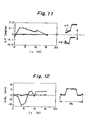
- Fiure 11 shows variation of the angle between a flange and an arm with respect to longitudinal distance
- Figure 12 shows variation of width with respect to longitudinal distance
- Figure 11 is a graph obtained by plotting variation ( ⁇ , degree) of an angle ( ⁇ ) of an arm before and after correction with respect to longitudinal distance (L 0 ) of a U-shaped steel sheet pile.
- variation was substantially constant regardless of the longitudinal distance.
- the arm was bent downwardly.
- the arm was bent upwardly or downwardly in conventional methods (0), but the tendency of deformation was the same as in this case.
- Figure 12 is a graph obtained by plotting variation ( ⁇ W 0 ) in width (W 0 ) before and after correction with respect to longitudinal distance (L 0 ) of a U-shaped steel sheet pile.
- examples of the present invention are indicated by the symbol •, and examples of the conventional method are indicated by the symbol 0. In the case of the present invention, there was substantially no variation.
- Figure 13 shows variation ( ⁇ ) of the angle ( ⁇ ) of an arm before and after correction with respect to longitudinal distance (L 0 )
- Figure 14 shows variation ( ⁇ W 0 ) of the width (W 0 ) before and after correction with respect to longitudinal distance (L 0 ).
- the symbol • indicates the case in which a tapered portion was not provided
- the symbol "+” indicates the case in which rollers with tapered portions were employed.
- the arm was bent upwardly or downwardly in the case in which the tapered portion was not provided (•), but the tendency of deformation was the same as in this case.
- Correctiong rollers of the present invention can be used to achieve roller correction of U-shaped steel sheet piles having an arm portion without changes in the sectional shape of the pile, i.e., the width size and the angle between arm and flange portions.
- the present invention has a marked effectiveness from an industrial point.
Landscapes
- Engineering & Computer Science (AREA)
- Mechanical Engineering (AREA)
- Bulkheads Adapted To Foundation Construction (AREA)
- Metal Rolling (AREA)
- Straightening Metal Sheet-Like Bodies (AREA)
- Placing Or Removing Of Piles Or Sheet Piles, Or Accessories Thereof (AREA)
Applications Claiming Priority (5)
| Application Number | Priority Date | Filing Date | Title |
|---|---|---|---|
| JP25376495 | 1995-09-29 | ||
| JP7253764A JP2874611B2 (ja) | 1995-09-29 | 1995-09-29 | 腕部を有するu形鋼矢板のローラ矯正方法 |
| JP34356695 | 1995-12-28 | ||
| JP07343566A JP3129179B2 (ja) | 1995-12-28 | 1995-12-28 | U型鋼矢板の矯正方法および矯正治具 |
| EP96931237A EP0795364B1 (de) | 1995-09-29 | 1996-09-18 | Verfahren zur korrektur einer u-förmigen spundbohle aus stahl |
Related Parent Applications (2)
| Application Number | Title | Priority Date | Filing Date |
|---|---|---|---|
| EP96931237A Division EP0795364B1 (de) | 1995-09-29 | 1996-09-18 | Verfahren zur korrektur einer u-förmigen spundbohle aus stahl |
| EP96931237.0 Division | 1997-04-10 |
Publications (2)
| Publication Number | Publication Date |
|---|---|
| EP1338351A1 true EP1338351A1 (de) | 2003-08-27 |
| EP1338351B1 EP1338351B1 (de) | 2011-04-27 |
Family
ID=26541385
Family Applications (2)
| Application Number | Title | Priority Date | Filing Date |
|---|---|---|---|
| EP03002697A Expired - Lifetime EP1338351B1 (de) | 1995-09-29 | 1996-09-18 | Verfahren zur Korrektur von U-förmigen Stahlspundbohlen |
| EP96931237A Expired - Lifetime EP0795364B1 (de) | 1995-09-29 | 1996-09-18 | Verfahren zur korrektur einer u-förmigen spundbohle aus stahl |
Family Applications After (1)
| Application Number | Title | Priority Date | Filing Date |
|---|---|---|---|
| EP96931237A Expired - Lifetime EP0795364B1 (de) | 1995-09-29 | 1996-09-18 | Verfahren zur korrektur einer u-förmigen spundbohle aus stahl |
Country Status (7)
| Country | Link |
|---|---|
| EP (2) | EP1338351B1 (de) |
| KR (1) | KR100480243B1 (de) |
| CN (2) | CN1073893C (de) |
| AU (1) | AU692404B2 (de) |
| DE (2) | DE69630670T2 (de) |
| TW (1) | TW346422B (de) |
| WO (1) | WO1997012701A1 (de) |
Families Citing this family (10)
| Publication number | Priority date | Publication date | Assignee | Title |
|---|---|---|---|---|
| WO2010092746A1 (ja) * | 2009-02-12 | 2010-08-19 | 新日本製鐵株式会社 | 地中連続壁用鋼材の製造方法 |
| CN103028920B (zh) * | 2011-09-30 | 2016-08-31 | 鞍钢重型机械有限责任公司 | 巷道用u形钢支架修复整形机 |
| CN102527773A (zh) * | 2011-10-31 | 2012-07-04 | 苏州金牛精密机械有限公司 | 钣金件校正装置 |
| JP5773857B2 (ja) * | 2011-12-12 | 2015-09-02 | 日立造船株式会社 | 鋼板ブロックの製造方法 |
| JP6436181B2 (ja) * | 2016-06-27 | 2018-12-12 | Jfeスチール株式会社 | 鋼矢板の曲がり矯正方法及び曲がり矯正装置 |
| CN109261752B (zh) * | 2018-09-06 | 2020-10-02 | 安庆美特优智能科技有限公司 | 新能源用檩条整形设备 |
| CN110052511A (zh) * | 2019-03-20 | 2019-07-26 | 新乡天丰机械制造有限公司 | 一种在线调整的腰高矫直装置 |
| EP3974078A4 (de) * | 2019-05-20 | 2022-07-13 | JFE Steel Corporation | Verfahren zur herstellung eines gepressten bauteils und formkorrekturwerkzeug |
| CN110449490A (zh) * | 2019-08-29 | 2019-11-15 | 安徽江淮汽车集团股份有限公司 | 一种u型梁整形工装及相应整形方法 |
| KR20230067643A (ko) * | 2020-11-20 | 2023-05-16 | 제이에프이 스틸 가부시키가이샤 | 강널말뚝의 교정 장치, 교정 방법 및 강널말뚝의 제조 방법 |
Family Cites Families (7)
| Publication number | Priority date | Publication date | Assignee | Title |
|---|---|---|---|---|
| DE332562C (de) * | 1920-02-03 | 1921-02-07 | Berlin Erfurter Maschinenfabri | Festklemmvorrichtung an Biegemaschinen fuer Profileisen |
| JPS5427836B2 (de) * | 1973-10-25 | 1979-09-12 | ||
| JPS5379759A (en) * | 1976-12-24 | 1978-07-14 | Nippon Steel Corp | U steel sheet pile correcting process |
| JPS5476471A (en) * | 1977-11-30 | 1979-06-19 | Sumitomo Metal Ind Ltd | Roller straightening method for steel shape and vertical roller for use of this method |
| JPS5570418A (en) * | 1978-11-24 | 1980-05-27 | Nippon Kokan Kk <Nkk> | Roller leveler for u-type steel sheet pile |
| JPS582492Y2 (ja) * | 1979-12-28 | 1983-01-17 | 新日本製鐵株式会社 | 鋼矢板の幅矯正装置 |
| JPS6163316A (ja) * | 1984-09-06 | 1986-04-01 | Kawasaki Steel Corp | U形鋼矢板の矯正ロ−ラ |
-
1996
- 1996-09-18 KR KR1019970703572A patent/KR100480243B1/ko not_active IP Right Cessation
- 1996-09-18 EP EP03002697A patent/EP1338351B1/de not_active Expired - Lifetime
- 1996-09-18 EP EP96931237A patent/EP0795364B1/de not_active Expired - Lifetime
- 1996-09-18 AU AU70003/96A patent/AU692404B2/en not_active Expired
- 1996-09-18 CN CN96191140A patent/CN1073893C/zh not_active Expired - Lifetime
- 1996-09-18 DE DE69630670T patent/DE69630670T2/de not_active Expired - Lifetime
- 1996-09-18 WO PCT/JP1996/002680 patent/WO1997012701A1/ja active IP Right Grant
- 1996-09-18 DE DE69638361T patent/DE69638361D1/de not_active Expired - Lifetime
- 1996-09-18 CN CNB011030518A patent/CN1159120C/zh not_active Expired - Lifetime
- 1996-09-23 TW TW085111615A patent/TW346422B/zh not_active IP Right Cessation
Non-Patent Citations (1)
| Title |
|---|
| No relevant documents disclosed * |
Also Published As
| Publication number | Publication date |
|---|---|
| CN1165489A (zh) | 1997-11-19 |
| KR980700137A (ko) | 1998-03-30 |
| EP1338351B1 (de) | 2011-04-27 |
| KR100480243B1 (ko) | 2005-07-28 |
| AU7000396A (en) | 1997-04-28 |
| CN1073893C (zh) | 2001-10-31 |
| EP0795364A1 (de) | 1997-09-17 |
| EP0795364B1 (de) | 2003-11-12 |
| DE69638361D1 (de) | 2011-06-09 |
| CN1159120C (zh) | 2004-07-28 |
| EP0795364A4 (de) | 1999-06-09 |
| CN1313152A (zh) | 2001-09-19 |
| TW346422B (en) | 1998-12-01 |
| DE69630670D1 (de) | 2003-12-18 |
| AU692404B2 (en) | 1998-06-04 |
| WO1997012701A1 (fr) | 1997-04-10 |
| DE69630670T2 (de) | 2004-09-30 |
Similar Documents
| Publication | Publication Date | Title |
|---|---|---|
| EP1338351B1 (de) | Verfahren zur Korrektur von U-förmigen Stahlspundbohlen | |
| US6318141B1 (en) | Roller leveller | |
| EP3370891B1 (de) | Biegeverfahren | |
| JPH1015619A (ja) | 曲げ加工鋼板、鋼板の曲げ加工方法及び鋼板の曲げ加工用ロールフォーミング装置 | |
| US6705145B1 (en) | Method of processing bent and deformed portion of metal material | |
| JP2874611B2 (ja) | 腕部を有するu形鋼矢板のローラ矯正方法 | |
| JP5332922B2 (ja) | T形鋼の矯正方法および矯正設備 | |
| EP2384832B1 (de) | Walzbiegevorrichtung und diese verwendendes verfahren zum biegen einer stahlplatte | |
| JP7260858B2 (ja) | 鋼矢板の矯正装置、矯正方法および鋼矢板の製造方法 | |
| JP3183077B2 (ja) | カットt形鋼の製造方法及び装置 | |
| JP7544081B2 (ja) | ハット形鋼矢板の製造方法 | |
| JP4412442B2 (ja) | ローラレベラによる金属板の矯正方法 | |
| JPH11342401A (ja) | 形鋼およびその製造方法 | |
| JP2991066B2 (ja) | H形鋼のローラ矯正方法 | |
| JPS6243767B2 (de) | ||
| JP3817762B2 (ja) | H形鋼のローラ矯正方法及びその装置 | |
| JP3281537B2 (ja) | ロール矯正機による鋼板矯正方法 | |
| JPS59156515A (ja) | 厚鋼板の平坦度矯正方法 | |
| JP2798008B2 (ja) | ロール成形方法 | |
| JPH0829331B2 (ja) | 熱間成形ローラー及び溝形材の熱間成形方法 | |
| JPH03184621A (ja) | フープ材のキャンバー矯正方法 | |
| JPH08215755A (ja) | H形鋼のローラ矯正装置 | |
| JPS60238036A (ja) | ロ−ラレベラ | |
| JPH09182916A (ja) | U型鋼矢板の矯正方法および矯正治具 | |
| JPH04197527A (ja) | 溝形材の形状矯正用ローラー |
Legal Events
| Date | Code | Title | Description |
|---|---|---|---|
| PUAI | Public reference made under article 153(3) epc to a published international application that has entered the european phase |
Free format text: ORIGINAL CODE: 0009012 |
|
| AC | Divisional application: reference to earlier application |
Ref document number: 0795364 Country of ref document: EP Kind code of ref document: P |
|
| AK | Designated contracting states |
Designated state(s): DE GB LU NL |
|
| 17P | Request for examination filed |
Effective date: 20031016 |
|
| AKX | Designation fees paid |
Designated state(s): DE GB LU NL |
|
| GRAP | Despatch of communication of intention to grant a patent |
Free format text: ORIGINAL CODE: EPIDOSNIGR1 |
|
| GRAS | Grant fee paid |
Free format text: ORIGINAL CODE: EPIDOSNIGR3 |
|
| GRAA | (expected) grant |
Free format text: ORIGINAL CODE: 0009210 |
|
| AC | Divisional application: reference to earlier application |
Ref document number: 0795364 Country of ref document: EP Kind code of ref document: P |
|
| AK | Designated contracting states |
Kind code of ref document: B1 Designated state(s): DE GB LU NL |
|
| REG | Reference to a national code |
Ref country code: GB Ref legal event code: FG4D |
|
| REF | Corresponds to: |
Ref document number: 69638361 Country of ref document: DE Date of ref document: 20110609 Kind code of ref document: P |
|
| REG | Reference to a national code |
Ref country code: DE Ref legal event code: R096 Ref document number: 69638361 Country of ref document: DE Effective date: 20110609 |
|
| REG | Reference to a national code |
Ref country code: NL Ref legal event code: VDEP Effective date: 20110427 |
|
| PG25 | Lapsed in a contracting state [announced via postgrant information from national office to epo] |
Ref country code: NL Free format text: LAPSE BECAUSE OF FAILURE TO SUBMIT A TRANSLATION OF THE DESCRIPTION OR TO PAY THE FEE WITHIN THE PRESCRIBED TIME-LIMIT Effective date: 20110427 |
|
| PLBE | No opposition filed within time limit |
Free format text: ORIGINAL CODE: 0009261 |
|
| STAA | Information on the status of an ep patent application or granted ep patent |
Free format text: STATUS: NO OPPOSITION FILED WITHIN TIME LIMIT |
|
| 26N | No opposition filed |
Effective date: 20120130 |
|
| REG | Reference to a national code |
Ref country code: DE Ref legal event code: R097 Ref document number: 69638361 Country of ref document: DE Effective date: 20120130 |
|
| REG | Reference to a national code |
Ref country code: GB Ref legal event code: 732E Free format text: REGISTERED BETWEEN 20131010 AND 20131016 |
|
| REG | Reference to a national code |
Ref country code: DE Ref legal event code: R082 Ref document number: 69638361 Country of ref document: DE Representative=s name: PATENTANWAELTE VON PUTTKAMER - BERNGRUBER, DE |
|
| REG | Reference to a national code |
Ref country code: DE Ref legal event code: R082 Ref document number: 69638361 Country of ref document: DE Representative=s name: PATENTANWAELTE VON PUTTKAMER - BERNGRUBER, DE Effective date: 20140402 Ref country code: DE Ref legal event code: R081 Ref document number: 69638361 Country of ref document: DE Owner name: NIPPON STEEL & SUMITOMO METAL CORPORATION, JP Free format text: FORMER OWNER: SUMITOMO METAL INDUSTRIES, LTD., OSAKA, JP Effective date: 20140402 Ref country code: DE Ref legal event code: R082 Ref document number: 69638361 Country of ref document: DE Representative=s name: VP-IP VON PUTTKAMER BERNGRUBER LOTH SPUHLER PA, DE Effective date: 20140402 Ref country code: DE Ref legal event code: R082 Ref document number: 69638361 Country of ref document: DE Representative=s name: LS-MP VON PUTTKAMER BERNGRUBER LOTH SPUHLER PA, DE Effective date: 20140402 Ref country code: DE Ref legal event code: R082 Ref document number: 69638361 Country of ref document: DE Representative=s name: LS-MP VON PUTTKAMER BERNGRUBER LOTH SPUHLER MU, DE Effective date: 20140402 |
|
| PGFP | Annual fee paid to national office [announced via postgrant information from national office to epo] |
Ref country code: DE Payment date: 20150916 Year of fee payment: 20 Ref country code: GB Payment date: 20150916 Year of fee payment: 20 |
|
| PGFP | Annual fee paid to national office [announced via postgrant information from national office to epo] |
Ref country code: LU Payment date: 20151005 Year of fee payment: 20 |
|
| REG | Reference to a national code |
Ref country code: DE Ref legal event code: R071 Ref document number: 69638361 Country of ref document: DE |
|
| REG | Reference to a national code |
Ref country code: GB Ref legal event code: PE20 Expiry date: 20160917 |
|
| PG25 | Lapsed in a contracting state [announced via postgrant information from national office to epo] |
Ref country code: GB Free format text: LAPSE BECAUSE OF EXPIRATION OF PROTECTION Effective date: 20160917 |