EP1337343B1 - Schnecke für eine vollmantel-schneckenzentrifuge und verfahren zur ölgewinnung mit einer vollmantel-schneckenzentrifuge - Google Patents
Schnecke für eine vollmantel-schneckenzentrifuge und verfahren zur ölgewinnung mit einer vollmantel-schneckenzentrifuge Download PDFInfo
- Publication number
- EP1337343B1 EP1337343B1 EP01993375A EP01993375A EP1337343B1 EP 1337343 B1 EP1337343 B1 EP 1337343B1 EP 01993375 A EP01993375 A EP 01993375A EP 01993375 A EP01993375 A EP 01993375A EP 1337343 B1 EP1337343 B1 EP 1337343B1
- Authority
- EP
- European Patent Office
- Prior art keywords
- screw
- blade
- recesses
- area
- blade segments
- Prior art date
- Legal status (The legal status is an assumption and is not a legal conclusion. Google has not performed a legal analysis and makes no representation as to the accuracy of the status listed.)
- Expired - Lifetime
Links
Images


Classifications
-
- B—PERFORMING OPERATIONS; TRANSPORTING
- B04—CENTRIFUGAL APPARATUS OR MACHINES FOR CARRYING-OUT PHYSICAL OR CHEMICAL PROCESSES
- B04B—CENTRIFUGES
- B04B1/00—Centrifuges with rotary bowls provided with solid jackets for separating predominantly liquid mixtures with or without solid particles
- B04B1/20—Centrifuges with rotary bowls provided with solid jackets for separating predominantly liquid mixtures with or without solid particles discharging solid particles from the bowl by a conveying screw coaxial with the bowl axis and rotating relatively to the bowl
- B04B2001/205—Centrifuges with rotary bowls provided with solid jackets for separating predominantly liquid mixtures with or without solid particles discharging solid particles from the bowl by a conveying screw coaxial with the bowl axis and rotating relatively to the bowl with special construction of screw thread, e.g. segments, height
-
- Y—GENERAL TAGGING OF NEW TECHNOLOGICAL DEVELOPMENTS; GENERAL TAGGING OF CROSS-SECTIONAL TECHNOLOGIES SPANNING OVER SEVERAL SECTIONS OF THE IPC; TECHNICAL SUBJECTS COVERED BY FORMER USPC CROSS-REFERENCE ART COLLECTIONS [XRACs] AND DIGESTS
- Y10—TECHNICAL SUBJECTS COVERED BY FORMER USPC
- Y10S—TECHNICAL SUBJECTS COVERED BY FORMER USPC CROSS-REFERENCE ART COLLECTIONS [XRACs] AND DIGESTS
- Y10S494/00—Imperforate bowl: centrifugal separators
- Y10S494/901—Imperforate bowl: centrifugal separators involving mixture containing oil
Definitions
- the invention relates to a screw for a solid bowl screw centrifuge according to the preamble of claim 1 and a method for oil extraction with a solid bowl centrifuge.
- a method that has proven particularly useful in olive oil production is from EP 0 557 758.
- a two-phase separation performed, in which the oil directly from a solid / water mixture is separated.
- the invention solves this problem on the one hand by a particularly advantageous Worm whose features are specified in claim 1. It also dissolves it a particularly advantageous method for oil extraction, the features in the claim 35 are indicated.
- a screw is provided for a solid bowl centrifuge, the sections in the conveyor track between adjacent Schnekken réellen has additional space segments. Furthermore, the screw blade is preferable provided with recesses which are formed such that a Flow through the material to be centrifuged between adjacent flights possible is.
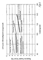
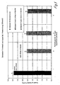
- the screw according to the invention By the screw according to the invention, the economy of oil production can be considerably increase. In this respect, in particular to the in the figure description referenced experiments, whose results in the figures 4 and 5 are shown. A particular advantage of the invention is to be seen in that the screw also easily retrofit existing centrifuges leaves.
- the screw according to the invention is particularly suitable for use in a process for oil extraction from fruits and seeds and for better drainage and / or de-oiling pulp from organic materials (e.g. Pulp mash, animal tissues such as fish, egg, gout cells).
- a Combination of recesses and blade segments provide, wherein the blade segments and the recesses are preferably formed in the axial direction are that the recesses each in the axial direction (and / or angled or zig-zag to the central axis y) form extending channels in which the Leaf segments are standing.
- blade segments and the recesses are formed only in the cylindrical portion of the screw body and when in the conical section of the screw, especially in the two-phase separation a baffle plate is provided.
- leaf-segment-like screw threads for example from WO 97/23295.
- these leaf segments extend into the conical section, which is unfavorable according to the invention is.
- they are on the circumference of the screw body in its entire area distributed, which has also proved to be of little benefit.
- the additional blade segments in the conveyor track are formed so that they are in the range of solids or the solids but preferably an outer region of e.g. 25 mm is not reached by the leaf segments, since in this area already relative completely de-oiled and permanently discharged solids are present.
- a solids slurry preferably via a rectangular tube, in the drum is fed.
- the rectangular tube must be so long that the incoming, protected to be centrifuged by the oil layer is brought to this subsequently not remix.
- the separation zone is quite close to the screw body a (10, 20 ..., to 40 to 50 mm distance).
- the fresh oil is as clean Phase only 20 to 30 mm outside the slug body recognize.
- the introduced solid as part of the supplied suspension is thus the machine Fill so far that this up to the oil separation zone (about 10, 20 ... to a maximum of 40 to 50 mm outside the screw body) is filled with solid suspensions.
- the oil separation zone about 10, 20 ... to a maximum of 40 to 50 mm outside the screw body
- solid suspensions are filled with solid suspensions.
- the solid is drier on the outside than inside In other words, the dry matter content on the drum side is much higher than the dry matter content towards the interior.
- the solid In the area of the leading leaf segments, the solid additionally becomes axially pressed together. He is then relaxed in the area of the recesses. It results thus an effect of pressure increases and relaxation. Essentially in the relaxation area the oil release takes place, which is thus more effective than without the additional relaxation zones.
- the worm body has a cylindrical in its rear region Section and in its adjoining front area one substantially conically uniform or uneven - e.g. stepped - tapered section on, with the recesses and leaf segments exclusively are formed in the region of the cylindrical portion.
- the screw body in the cylindrical portion initially at least one helix, which is free of recesses and free of leaf segments is formed, which is followed by further worm threads, which with the Recesses and leaf segments are provided.
- Oil drain channels are formed.
- the recesses have a remaining portion of the screw blade on the circumference of the screw body.
- the leaf segments - based on one or more flights - Evenly or unevenly distributed on the circumference of the screw body.
- the area of the recesses is about 25-60%, in particular 40 - 50% of the worm gear area.
- the recesses in the screw blades are designed such that they project radially beyond at least the area of the solid zone (for example 70-95%, preferably 70-100% of the screw blade height).
- the height of the leaf segments is about 0 - 30% lower than that Screw blade height.
- the blade segments are designed as rectangular plates conceivable are also trapezoidal, rounded and / or from the snail body outwardly tapering or widening shaped elements.
- Fig. 1 shows a screw 1 for a solid bowl screw centrifuge, wherein the Screw a worm body 3 and here a worm body 3 several times surrounding worm blade 5, which has a plurality of flights (x, x + 1, x + 2, etc.).
- a conveyor track 7 for Fördem / transport formed to be processed centrifuged is a conveyor track 7 for Fördem / transport formed to be processed centrifuged.
- the screw body 3 has in its rear in Fig. 1 area a cylindrical Section 9 and in his in Fig. 1 adjoining the front area a conically tapering section 11.
- the centrifuged material S is through the centrally disposed, adjustable inlet pipe 14th in an inlet chamber 15 and from there through openings 17 in the drum space 19 with the screw 1 and the screw 1 surrounding drum 21 passed.
- these Einlaufkammem 15 and openings 17 (or special Distributor) in the embodiment of Fig. 1 at the rear end of the cylindrical Section 3 arranged.
- the centrifuged material S is accelerated to the operating speed.
- the solid particles settle in the shortest possible time Time off at the drum wall.
- the screw 1 rotates at a speed slightly lower or higher than the drum 21 and promotes the ejected solid F to the conical section 11 out of the drum 21 for solids 23.
- the liquid L flows toward the larger drum diameter at the rear End of the drum 21 and is derived there (overflow 25).
- the worm 1 of Figure 1 points from its second flight (X + 1) to its fifth flight (X + 4) recesses 27 in the screw on.
- recesses 27 are formed in the embodiment of FIG. 1 such that in the axial direction from the second to the fifth screw blade forming extending axial channels K.
- a single helix with Recesses 27 and blade segments 29 is in a simplified embodiment also conceivable.
- additional leaf segments 29 are arranged here as Metal strips are formed here from the outer periphery of the Schnekken stresses 3 outwardly widening trapezoidal shape.
- the separation of the leaf sections or segments can either take place in such a way that that the screw blade 5 is separated to the circumference of the screw body 3 becomes. Alternatively, however, a remaining portion 30 of the screw blade 5 on The circumference of the screw body 3 stop. Is the removal essentially radially to the drum and screw axis y, resulting trapezoidal Leaf segments 29.
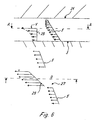
- Fig. 6a, b show the velocity profiles in a helix in the area the recesses and leaf segments.
- Fig. 6a it is clear that "in the shade" of the leaf segment, the velocity of the particles increases from the inside to the outside.
- the maximum value is reached, which According to Fig. 6b at the upper leaf segment edge again substantially constant is.
- the screw 1 - in Fig. 1 from the rear inlet zone forward looking at the conical section - at first some turns x-1, x, x + 1 on, in the area of the screw blade 5 each continuous or free of recesses is trained.
- at least one or two flights are x continuously formed. In this area are also no additional Leaf segments 29 provided in the conveyor track 7.
- This zone is followed by some worm threads x + 2, ... x + 5, which with the recesses 27 are provided and in the interstices or in the Conveyor tracks 7 each formed the blade segments 29 or erected (welded) are.
- This zone extends maximally to the beginning of the conical section 11th the screw 1.
- the baffle plate 13 is arranged.
- the snail should be formed free of recesses, also in the conveyor track 7 and no additional Leaf segments 29 are arranged.
- Per screw flight are preferably 2 to 6, especially 3 to 5, especially preferably 4 recesses 27 formed.
- the blade segments 29 are uniformly on the circumference of the screw body 3 distributed.
- the worm threads x are relative to the central axis or to the axis of symmetry y Screw 1 each arranged at an angle or close to the central axis one Angle ⁇ on.
- the amount of the angle ⁇ (measured at the bottom of the Schnekkenblattes 5), is preferably between 60 and 85 °, in particular at 75 to 80 °.
- the blade segments close with the symmetry axis y a Angle ⁇ one smaller than ⁇ .
- ⁇ is between 40 and 70 °, in particular 50 to 55 °.
- the blade segments 29 are substantially parallel to the To align the worm blade 5 (maximum difference angle between ⁇ and ⁇ preferably about 10 - 11 °).
- the surface of the recesses is about 50 ° of the checkered surface.
- the angular size ( ⁇ ) is determined by the fact that the Width of the distance (a) - viewed in orthogonal extension of the edges - between the blade longitudinal edge and the recess edge 27 at 0 to 28%, in particular at 15 to 25% of the distance of a pair of flights - preferably considered at the base of the snail (inside), depending on the shape - lies.
- the height h of the Blade segments (measured from the outer circumference of the screw body 3).
- the height h of Blade segments 29 is selected such that it extends into the region of the solid zone extend. Accordingly, the screw blades 5 should have recesses 27, which project radially beyond at least the region of the solid zone.
- the height h is selected about 30 mm lower than the Schneckenblatt height k.
- the worm blade closes with the peripheral wall of the worm body 3 according to FIG. 2b further includes an angle ⁇ . This is preferably smaller as the angle ⁇ , which the blade segment 29 encloses with the screw body 3.
Landscapes
- Centrifugal Separators (AREA)
Applications Claiming Priority (3)
| Application Number | Priority Date | Filing Date | Title |
|---|---|---|---|
| DE10055798 | 2000-11-10 | ||
| DE10055798A DE10055798A1 (de) | 2000-11-10 | 2000-11-10 | Schnecke für eine Vollmantel-Schneckenzentrifuge und Verfahren zur Ölgewinnung mit einer Vollmantel-Schneckenzentrifuge |
| PCT/EP2001/012069 WO2002038278A1 (de) | 2000-11-10 | 2001-10-18 | Schnecke für eine vollmantel-schneckenzentrifuge und verfahren zur ölgewinnung mit einer vollmantel-schneckenzentrifuge |
Publications (2)
| Publication Number | Publication Date |
|---|---|
| EP1337343A1 EP1337343A1 (de) | 2003-08-27 |
| EP1337343B1 true EP1337343B1 (de) | 2005-02-09 |
Family
ID=7662853
Family Applications (1)
| Application Number | Title | Priority Date | Filing Date |
|---|---|---|---|
| EP01993375A Expired - Lifetime EP1337343B1 (de) | 2000-11-10 | 2001-10-18 | Schnecke für eine vollmantel-schneckenzentrifuge und verfahren zur ölgewinnung mit einer vollmantel-schneckenzentrifuge |
Country Status (10)
| Country | Link |
|---|---|
| US (1) | US6908423B2 (da) |
| EP (1) | EP1337343B1 (da) |
| JP (1) | JP2004512945A (da) |
| AR (1) | AR031307A1 (da) |
| AT (1) | ATE288790T1 (da) |
| DE (2) | DE10055798A1 (da) |
| DK (1) | DK1337343T3 (da) |
| ES (2) | ES1048837Y (da) |
| PT (1) | PT1337343E (da) |
| WO (1) | WO2002038278A1 (da) |
Families Citing this family (16)
| Publication number | Priority date | Publication date | Assignee | Title |
|---|---|---|---|---|
| DE10055798A1 (de) * | 2000-11-10 | 2002-05-23 | Westfalia Separator Ind Gmbh | Schnecke für eine Vollmantel-Schneckenzentrifuge und Verfahren zur Ölgewinnung mit einer Vollmantel-Schneckenzentrifuge |
| DE20208119U1 (de) * | 2002-05-24 | 2002-08-14 | Hiller GmbH, 84137 Vilsbiburg | Dekantierzentrifuge für die Gewinnung von Frucht- oder Gemüsesäften |
| US7001324B2 (en) * | 2003-01-08 | 2006-02-21 | Hutchison Hayes, L. P. | Method of retrofitting a decanting centrifuge |
| JP2006124424A (ja) * | 2004-10-26 | 2006-05-18 | Miyoshi Oil & Fat Co Ltd | 油脂の分別処理方法 |
| DE102005061461A1 (de) * | 2005-12-22 | 2007-07-05 | Westfalia Separator Ag | Vollmantel-Schneckenzentrifuge |
| DE102006056934A1 (de) * | 2006-11-30 | 2008-06-05 | Westfalia Separator Ag | Verfahren zur zentrifugalen Klärung eines ölhaltigen Sandes |
| DE102010027598A1 (de) | 2010-07-20 | 2012-01-26 | Gea Mechanical Equipment Gmbh | Verfahren zur Klärung eines Wein-Gelägers |
| CN102199891B (zh) * | 2011-05-17 | 2013-05-01 | 江西洪都精工机械有限公司 | 带有螺旋推进和搅拌碎解功能的组合转子及制造方法 |
| PT2586533T (pt) * | 2011-10-28 | 2019-11-21 | Flottweg Se | Centrífuga de parafuso contínuo de parede sólida com um parafuso contínuo |
| KR101508057B1 (ko) | 2013-07-19 | 2015-04-07 | 주식회사 일성 | 진공흡입펌프 |
| KR101490746B1 (ko) | 2014-06-09 | 2015-02-06 | 주식회사 화인 | 탈수 성능이 향상된 원심 탈수기 |
| CN109482370A (zh) * | 2018-12-20 | 2019-03-19 | 上海市离心机械研究所有限公司 | 一种用于橄榄油油相提取的卧螺离心机螺旋结构 |
| KR102170275B1 (ko) * | 2019-01-30 | 2020-10-26 | 백도선 | 친환경 준설토 처리 시스템 |
| DE102019102623A1 (de) | 2019-02-04 | 2020-08-06 | Gea Mechanical Equipment Gmbh | Verfahren zum Klären einer Suspension von Feststoffen |
| CN111729763A (zh) * | 2020-07-27 | 2020-10-02 | 坚纳森(青岛)机械有限公司 | 一种离心机转子结构 |
| CN112827665A (zh) * | 2021-01-21 | 2021-05-25 | 巨能机械(中国)有限公司 | 带副叶片的螺旋输送器与螺旋卸料沉降离心机 |
Family Cites Families (16)
| Publication number | Priority date | Publication date | Assignee | Title |
|---|---|---|---|---|
| GB733515A (en) * | 1952-05-28 | 1955-07-13 | Separator Ab | Improvements in or relating to the separating of liquids and solids |
| JPS57194061A (en) * | 1981-05-26 | 1982-11-29 | Kobe Steel Ltd | Centrifugal concentrating device |
| DE3301099A1 (de) * | 1983-01-14 | 1984-12-06 | KHD Humboldt Wedag AG, 5000 Köln | Vorrichtung zur entfeuchtung von schlamm im zentrifugalfeld einer vollmantel-zentrifuge |
| DE3318793A1 (de) * | 1983-05-24 | 1985-01-24 | KHD Humboldt Wedag AG, 5000 Köln | Vorrichtung zum entfeuchten von schlamm |
| GB8620436D0 (en) * | 1986-08-22 | 1986-10-01 | Mozley R H | Centrifugal solids-liquids separator |
| ATE114508T1 (de) * | 1988-06-24 | 1994-12-15 | Mozley Ltd Richard | Festflüssig-separator. |
| US5222935A (en) * | 1991-06-21 | 1993-06-29 | Flottweg Gmbh | Centrifuge with a screw and bristles for separating a suspension into a solids phase and at least one liquid phase |
| DE4132593A1 (de) * | 1991-09-30 | 1993-04-01 | Linde Kca Dresden Gmbh | Reaktor zur gegenstrombehandlung von feststoff und fluessigkeit |
| DE4132693A1 (de) | 1991-10-01 | 1993-04-08 | Messer Griesheim Gmbh | Verfahren und vorrichtung zur herstellung von pulvern |
| DE4206006C1 (da) | 1992-02-27 | 1993-09-16 | Westfalia Separator Ag, 59302 Oelde, De | |
| US5354255A (en) * | 1992-12-17 | 1994-10-11 | Alfa Laval Separation Inc. | Decanter centrifuge with conveyor capable of high speed and higher flow rates |
| IT1269436B (it) * | 1994-01-17 | 1997-04-01 | Nuova Maip Macchine Agric | Procedimento per l'ottenimento di mosto da grappoli di uva comprendente almeno una fase di centrifugazione del grappolo stesso |
| SE505557C2 (sv) | 1995-12-21 | 1997-09-15 | Alfa Laval Separation Ab | Dekantercentrifug |
| DE10055798A1 (de) * | 2000-11-10 | 2002-05-23 | Westfalia Separator Ind Gmbh | Schnecke für eine Vollmantel-Schneckenzentrifuge und Verfahren zur Ölgewinnung mit einer Vollmantel-Schneckenzentrifuge |
| DE20208119U1 (de) * | 2002-05-24 | 2002-08-14 | Hiller GmbH, 84137 Vilsbiburg | Dekantierzentrifuge für die Gewinnung von Frucht- oder Gemüsesäften |
| ES2217926B1 (es) * | 2002-05-28 | 2006-02-16 | Josep Sallent Soler | Proceso continuo para la obtencion de aceite de oliva con extraccion al vacio o presion negativa. |
-
2000
- 2000-11-10 DE DE10055798A patent/DE10055798A1/de not_active Withdrawn
-
2001
- 2001-04-04 ES ES200100838U patent/ES1048837Y/es not_active Expired - Fee Related
- 2001-10-18 JP JP2002540851A patent/JP2004512945A/ja active Pending
- 2001-10-18 EP EP01993375A patent/EP1337343B1/de not_active Expired - Lifetime
- 2001-10-18 ES ES01993375T patent/ES2233712T3/es not_active Expired - Lifetime
- 2001-10-18 US US10/311,874 patent/US6908423B2/en not_active Expired - Fee Related
- 2001-10-18 DK DK01993375T patent/DK1337343T3/da active
- 2001-10-18 DE DE50105332T patent/DE50105332D1/de not_active Expired - Lifetime
- 2001-10-18 WO PCT/EP2001/012069 patent/WO2002038278A1/de active IP Right Grant
- 2001-10-18 AT AT01993375T patent/ATE288790T1/de not_active IP Right Cessation
- 2001-10-18 PT PT01993375T patent/PT1337343E/pt unknown
- 2001-11-07 AR ARP010105218A patent/AR031307A1/es unknown
Also Published As
| Publication number | Publication date |
|---|---|
| US6908423B2 (en) | 2005-06-21 |
| DE10055798A1 (de) | 2002-05-23 |
| ATE288790T1 (de) | 2005-02-15 |
| PT1337343E (pt) | 2005-04-29 |
| US20030129042A1 (en) | 2003-07-10 |
| AR031307A1 (es) | 2003-09-17 |
| ES1048837U (es) | 2001-10-01 |
| DK1337343T3 (da) | 2005-05-30 |
| ES2233712T3 (es) | 2005-06-16 |
| JP2004512945A (ja) | 2004-04-30 |
| DE50105332D1 (de) | 2005-03-17 |
| EP1337343A1 (de) | 2003-08-27 |
| ES1048837Y (es) | 2002-02-16 |
| WO2002038278A1 (de) | 2002-05-16 |
Similar Documents
| Publication | Publication Date | Title |
|---|---|---|
| EP1337343B1 (de) | Schnecke für eine vollmantel-schneckenzentrifuge und verfahren zur ölgewinnung mit einer vollmantel-schneckenzentrifuge | |
| EP1968749B1 (de) | Vollmantel-schneckenzentrifuge | |
| DE754339C (de) | Verfahren und Vorrichtung zum Entfernen von schweren Teilchen unter Fliehkraftwirkung aus einer Aufschwemmung, insbesondere von Zellstoff, Papierstoff u. dgl. | |
| DE69315109T2 (de) | Schneckenzentrifuge mit unterbrochenen Schneckenwendeln im konischen Austragsmantelteil | |
| DE2930581A1 (de) | Zentrifuge zum sortieren und trennen von feststoffen | |
| EP2155353B1 (de) | Pressschneckenseparator | |
| DE3043194A1 (de) | Einrichtung zum mechanischen trennen von fluessigkeiten aus fluessigkeitsfeststoffgemischen in einer schneckenpresse | |
| DE2130633A1 (de) | Vollmantelschneckenzentrifuge | |
| DE60318833T2 (de) | Dekantierzentrifuge | |
| DE3030980A1 (de) | Hydrozyklon. | |
| DE69307604T2 (de) | Ohne Zugabe von Trinkwasser arbeitende Zentrifuge zum Abscheiden von Öl aus Ölschlämmen | |
| DE3046946A1 (de) | Dekantierzentrifuge | |
| DE1024438B (de) | Verfahren zum Abscheiden von Feststoffen aus einer Fluessigkeit | |
| DE69612868T2 (de) | Dekantierzentrifuge | |
| DE3301099C2 (da) | ||
| DE102019102623A1 (de) | Verfahren zum Klären einer Suspension von Feststoffen | |
| DE1757779A1 (de) | Zentrifuge | |
| DE2208093A1 (de) | Zentrifuge | |
| DE60124554T2 (de) | Zentrifugalabscheider | |
| EP1260273B1 (de) | Vollmantel-Schneckenzentrifuge | |
| EP1383607B1 (de) | Vollmantel-schneckenzentrifuge und verfahren zur ölgewinnung mit einer vollmantel-schneckenzentrifuge | |
| DE102009001054A1 (de) | Vollmantel-Schneckenzentrifuge mit Grobstoff-Auslass | |
| EP0257270B1 (de) | Kontinuierlich arbeitende Zuckerzentrifuge | |
| EP0200096B1 (de) | Siebvorrichtung | |
| WO2001051165A1 (de) | Dekanter zum trennen zweier flüssiger phasen unterschiedlicher dichte |
Legal Events
| Date | Code | Title | Description |
|---|---|---|---|
| PUAI | Public reference made under article 153(3) epc to a published international application that has entered the european phase |
Free format text: ORIGINAL CODE: 0009012 |
|
| 17P | Request for examination filed |
Effective date: 20020511 |
|
| AK | Designated contracting states |
Designated state(s): AT BE CH CY DE DK ES FI FR GB GR IE IT LI LU MC NL PT SE TR |
|
| RAP1 | Party data changed (applicant data changed or rights of an application transferred) |
Owner name: WESTFALIA SEPARATOR AG |
|
| GRAP | Despatch of communication of intention to grant a patent |
Free format text: ORIGINAL CODE: EPIDOSNIGR1 |
|
| GRAS | Grant fee paid |
Free format text: ORIGINAL CODE: EPIDOSNIGR3 |
|
| GRAA | (expected) grant |
Free format text: ORIGINAL CODE: 0009210 |
|
| AK | Designated contracting states |
Kind code of ref document: B1 Designated state(s): AT BE CH CY DE DK ES FI FR GB GR IE IT LI LU MC NL PT SE TR |
|
| PG25 | Lapsed in a contracting state [announced via postgrant information from national office to epo] |
Ref country code: GB Free format text: LAPSE BECAUSE OF FAILURE TO SUBMIT A TRANSLATION OF THE DESCRIPTION OR TO PAY THE FEE WITHIN THE PRESCRIBED TIME-LIMIT Effective date: 20050209 Ref country code: NL Free format text: LAPSE BECAUSE OF FAILURE TO SUBMIT A TRANSLATION OF THE DESCRIPTION OR TO PAY THE FEE WITHIN THE PRESCRIBED TIME-LIMIT Effective date: 20050209 Ref country code: FI Free format text: LAPSE BECAUSE OF FAILURE TO SUBMIT A TRANSLATION OF THE DESCRIPTION OR TO PAY THE FEE WITHIN THE PRESCRIBED TIME-LIMIT Effective date: 20050209 Ref country code: TR Free format text: LAPSE BECAUSE OF FAILURE TO SUBMIT A TRANSLATION OF THE DESCRIPTION OR TO PAY THE FEE WITHIN THE PRESCRIBED TIME-LIMIT Effective date: 20050209 Ref country code: IE Free format text: LAPSE BECAUSE OF FAILURE TO SUBMIT A TRANSLATION OF THE DESCRIPTION OR TO PAY THE FEE WITHIN THE PRESCRIBED TIME-LIMIT Effective date: 20050209 |
|
| REG | Reference to a national code |
Ref country code: GB Ref legal event code: FG4D Free format text: NOT ENGLISH |
|
| REG | Reference to a national code |
Ref country code: CH Ref legal event code: EP |
|
| REG | Reference to a national code |
Ref country code: IE Ref legal event code: FG4D Free format text: GERMAN |
|
| REF | Corresponds to: |
Ref document number: 50105332 Country of ref document: DE Date of ref document: 20050317 Kind code of ref document: P |
|
| REG | Reference to a national code |
Ref country code: PT Ref legal event code: SC4A Free format text: AVAILABILITY OF NATIONAL TRANSLATION Effective date: 20050218 |
|
| REG | Reference to a national code |
Ref country code: GR Ref legal event code: EP Ref document number: 20050401279 Country of ref document: GR |
|
| REG | Reference to a national code |
Ref country code: DK Ref legal event code: T3 |
|
| REG | Reference to a national code |
Ref country code: SE Ref legal event code: TRGR |
|
| REG | Reference to a national code |
Ref country code: ES Ref legal event code: FG2A Ref document number: 2233712 Country of ref document: ES Kind code of ref document: T3 |
|
| NLV1 | Nl: lapsed or annulled due to failure to fulfill the requirements of art. 29p and 29m of the patents act | ||
| GBV | Gb: ep patent (uk) treated as always having been void in accordance with gb section 77(7)/1977 [no translation filed] |
Effective date: 20050209 |
|
| REG | Reference to a national code |
Ref country code: IE Ref legal event code: FD4D |
|
| PG25 | Lapsed in a contracting state [announced via postgrant information from national office to epo] |
Ref country code: CY Free format text: LAPSE BECAUSE OF FAILURE TO SUBMIT A TRANSLATION OF THE DESCRIPTION OR TO PAY THE FEE WITHIN THE PRESCRIBED TIME-LIMIT Effective date: 20051018 Ref country code: AT Free format text: LAPSE BECAUSE OF NON-PAYMENT OF DUE FEES Effective date: 20051018 |
|
| PG25 | Lapsed in a contracting state [announced via postgrant information from national office to epo] |
Ref country code: BE Free format text: LAPSE BECAUSE OF NON-PAYMENT OF DUE FEES Effective date: 20051031 Ref country code: MC Free format text: LAPSE BECAUSE OF NON-PAYMENT OF DUE FEES Effective date: 20051031 Ref country code: CH Free format text: LAPSE BECAUSE OF NON-PAYMENT OF DUE FEES Effective date: 20051031 Ref country code: LU Free format text: LAPSE BECAUSE OF NON-PAYMENT OF DUE FEES Effective date: 20051031 Ref country code: LI Free format text: LAPSE BECAUSE OF NON-PAYMENT OF DUE FEES Effective date: 20051031 |
|
| PLBE | No opposition filed within time limit |
Free format text: ORIGINAL CODE: 0009261 |
|
| STAA | Information on the status of an ep patent application or granted ep patent |
Free format text: STATUS: NO OPPOSITION FILED WITHIN TIME LIMIT |
|
| 26N | No opposition filed |
Effective date: 20051110 |
|
| ET | Fr: translation filed | ||
| REG | Reference to a national code |
Ref country code: CH Ref legal event code: PL |
|
| BERE | Be: lapsed |
Owner name: WESTFALIA SEPARATOR A.G. Effective date: 20051031 |
|
| REG | Reference to a national code |
Ref country code: FR Ref legal event code: PLFP Year of fee payment: 15 |
|
| PGFP | Annual fee paid to national office [announced via postgrant information from national office to epo] |
Ref country code: DK Payment date: 20151022 Year of fee payment: 15 |
|
| PGFP | Annual fee paid to national office [announced via postgrant information from national office to epo] |
Ref country code: SE Payment date: 20151022 Year of fee payment: 15 Ref country code: FR Payment date: 20151022 Year of fee payment: 15 |
|
| REG | Reference to a national code |
Ref country code: DK Ref legal event code: EBP Effective date: 20161031 |
|
| REG | Reference to a national code |
Ref country code: FR Ref legal event code: ST Effective date: 20170630 |
|
| PG25 | Lapsed in a contracting state [announced via postgrant information from national office to epo] |
Ref country code: FR Free format text: LAPSE BECAUSE OF NON-PAYMENT OF DUE FEES Effective date: 20161102 |
|
| PG25 | Lapsed in a contracting state [announced via postgrant information from national office to epo] |
Ref country code: SE Free format text: LAPSE BECAUSE OF NON-PAYMENT OF DUE FEES Effective date: 20161019 |
|
| PG25 | Lapsed in a contracting state [announced via postgrant information from national office to epo] |
Ref country code: DK Free format text: LAPSE BECAUSE OF NON-PAYMENT OF DUE FEES Effective date: 20161031 |
|
| PGFP | Annual fee paid to national office [announced via postgrant information from national office to epo] |
Ref country code: PT Payment date: 20200918 Year of fee payment: 20 |
|
| PGFP | Annual fee paid to national office [announced via postgrant information from national office to epo] |
Ref country code: ES Payment date: 20201103 Year of fee payment: 20 Ref country code: DE Payment date: 20201026 Year of fee payment: 20 Ref country code: GR Payment date: 20201027 Year of fee payment: 20 Ref country code: IT Payment date: 20201030 Year of fee payment: 20 |
|
| REG | Reference to a national code |
Ref country code: DE Ref legal event code: R071 Ref document number: 50105332 Country of ref document: DE |
|
| REG | Reference to a national code |
Ref country code: ES Ref legal event code: FD2A Effective date: 20220126 |
|
| PG25 | Lapsed in a contracting state [announced via postgrant information from national office to epo] |
Ref country code: PT Free format text: LAPSE BECAUSE OF EXPIRATION OF PROTECTION Effective date: 20211026 |
|
| PG25 | Lapsed in a contracting state [announced via postgrant information from national office to epo] |
Ref country code: ES Free format text: LAPSE BECAUSE OF EXPIRATION OF PROTECTION Effective date: 20211019 |