EP1332737B1 - Fussprothese mit gefedertem Knöchel - Google Patents
Fussprothese mit gefedertem Knöchel Download PDFInfo
- Publication number
- EP1332737B1 EP1332737B1 EP03003285A EP03003285A EP1332737B1 EP 1332737 B1 EP1332737 B1 EP 1332737B1 EP 03003285 A EP03003285 A EP 03003285A EP 03003285 A EP03003285 A EP 03003285A EP 1332737 B1 EP1332737 B1 EP 1332737B1
- Authority
- EP
- European Patent Office
- Prior art keywords
- foot
- plate
- ankle
- bladder
- prosthetic foot
- Prior art date
- Legal status (The legal status is an assumption and is not a legal conclusion. Google has not performed a legal analysis and makes no representation as to the accuracy of the status listed.)
- Expired - Lifetime
Links
Images


Classifications
-
- A—HUMAN NECESSITIES
- A61—MEDICAL OR VETERINARY SCIENCE; HYGIENE
- A61F—FILTERS IMPLANTABLE INTO BLOOD VESSELS; PROSTHESES; DEVICES PROVIDING PATENCY TO, OR PREVENTING COLLAPSING OF, TUBULAR STRUCTURES OF THE BODY, e.g. STENTS; ORTHOPAEDIC, NURSING OR CONTRACEPTIVE DEVICES; FOMENTATION; TREATMENT OR PROTECTION OF EYES OR EARS; BANDAGES, DRESSINGS OR ABSORBENT PADS; FIRST-AID KITS
- A61F2/00—Filters implantable into blood vessels; Prostheses, i.e. artificial substitutes or replacements for parts of the body; Appliances for connecting them with the body; Devices providing patency to, or preventing collapsing of, tubular structures of the body, e.g. stents
- A61F2/50—Prostheses not implantable in the body
- A61F2/68—Operating or control means
-
- A—HUMAN NECESSITIES
- A61—MEDICAL OR VETERINARY SCIENCE; HYGIENE
- A61F—FILTERS IMPLANTABLE INTO BLOOD VESSELS; PROSTHESES; DEVICES PROVIDING PATENCY TO, OR PREVENTING COLLAPSING OF, TUBULAR STRUCTURES OF THE BODY, e.g. STENTS; ORTHOPAEDIC, NURSING OR CONTRACEPTIVE DEVICES; FOMENTATION; TREATMENT OR PROTECTION OF EYES OR EARS; BANDAGES, DRESSINGS OR ABSORBENT PADS; FIRST-AID KITS
- A61F2/00—Filters implantable into blood vessels; Prostheses, i.e. artificial substitutes or replacements for parts of the body; Appliances for connecting them with the body; Devices providing patency to, or preventing collapsing of, tubular structures of the body, e.g. stents
- A61F2/50—Prostheses not implantable in the body
- A61F2/60—Artificial legs or feet or parts thereof
- A61F2/602—Artificial legs or feet or parts thereof with air cushions
-
- A—HUMAN NECESSITIES
- A61—MEDICAL OR VETERINARY SCIENCE; HYGIENE
- A61F—FILTERS IMPLANTABLE INTO BLOOD VESSELS; PROSTHESES; DEVICES PROVIDING PATENCY TO, OR PREVENTING COLLAPSING OF, TUBULAR STRUCTURES OF THE BODY, e.g. STENTS; ORTHOPAEDIC, NURSING OR CONTRACEPTIVE DEVICES; FOMENTATION; TREATMENT OR PROTECTION OF EYES OR EARS; BANDAGES, DRESSINGS OR ABSORBENT PADS; FIRST-AID KITS
- A61F2/00—Filters implantable into blood vessels; Prostheses, i.e. artificial substitutes or replacements for parts of the body; Appliances for connecting them with the body; Devices providing patency to, or preventing collapsing of, tubular structures of the body, e.g. stents
- A61F2/50—Prostheses not implantable in the body
- A61F2/60—Artificial legs or feet or parts thereof
- A61F2/66—Feet; Ankle joints
-
- A—HUMAN NECESSITIES
- A61—MEDICAL OR VETERINARY SCIENCE; HYGIENE
- A61F—FILTERS IMPLANTABLE INTO BLOOD VESSELS; PROSTHESES; DEVICES PROVIDING PATENCY TO, OR PREVENTING COLLAPSING OF, TUBULAR STRUCTURES OF THE BODY, e.g. STENTS; ORTHOPAEDIC, NURSING OR CONTRACEPTIVE DEVICES; FOMENTATION; TREATMENT OR PROTECTION OF EYES OR EARS; BANDAGES, DRESSINGS OR ABSORBENT PADS; FIRST-AID KITS
- A61F2/00—Filters implantable into blood vessels; Prostheses, i.e. artificial substitutes or replacements for parts of the body; Appliances for connecting them with the body; Devices providing patency to, or preventing collapsing of, tubular structures of the body, e.g. stents
- A61F2/50—Prostheses not implantable in the body
- A61F2/68—Operating or control means
- A61F2/74—Operating or control means fluid, i.e. hydraulic or pneumatic
- A61F2/741—Operating or control means fluid, i.e. hydraulic or pneumatic using powered actuators, e.g. stepper motors or solenoids
-
- A—HUMAN NECESSITIES
- A61—MEDICAL OR VETERINARY SCIENCE; HYGIENE
- A61F—FILTERS IMPLANTABLE INTO BLOOD VESSELS; PROSTHESES; DEVICES PROVIDING PATENCY TO, OR PREVENTING COLLAPSING OF, TUBULAR STRUCTURES OF THE BODY, e.g. STENTS; ORTHOPAEDIC, NURSING OR CONTRACEPTIVE DEVICES; FOMENTATION; TREATMENT OR PROTECTION OF EYES OR EARS; BANDAGES, DRESSINGS OR ABSORBENT PADS; FIRST-AID KITS
- A61F2/00—Filters implantable into blood vessels; Prostheses, i.e. artificial substitutes or replacements for parts of the body; Appliances for connecting them with the body; Devices providing patency to, or preventing collapsing of, tubular structures of the body, e.g. stents
- A61F2/50—Prostheses not implantable in the body
- A61F2/68—Operating or control means
- A61F2/74—Operating or control means fluid, i.e. hydraulic or pneumatic
- A61F2/748—Valve systems
-
- A—HUMAN NECESSITIES
- A61—MEDICAL OR VETERINARY SCIENCE; HYGIENE
- A61F—FILTERS IMPLANTABLE INTO BLOOD VESSELS; PROSTHESES; DEVICES PROVIDING PATENCY TO, OR PREVENTING COLLAPSING OF, TUBULAR STRUCTURES OF THE BODY, e.g. STENTS; ORTHOPAEDIC, NURSING OR CONTRACEPTIVE DEVICES; FOMENTATION; TREATMENT OR PROTECTION OF EYES OR EARS; BANDAGES, DRESSINGS OR ABSORBENT PADS; FIRST-AID KITS
- A61F2/00—Filters implantable into blood vessels; Prostheses, i.e. artificial substitutes or replacements for parts of the body; Appliances for connecting them with the body; Devices providing patency to, or preventing collapsing of, tubular structures of the body, e.g. stents
- A61F2/50—Prostheses not implantable in the body
- A61F2/60—Artificial legs or feet or parts thereof
- A61F2/66—Feet; Ankle joints
- A61F2/6607—Ankle joints
-
- A—HUMAN NECESSITIES
- A61—MEDICAL OR VETERINARY SCIENCE; HYGIENE
- A61F—FILTERS IMPLANTABLE INTO BLOOD VESSELS; PROSTHESES; DEVICES PROVIDING PATENCY TO, OR PREVENTING COLLAPSING OF, TUBULAR STRUCTURES OF THE BODY, e.g. STENTS; ORTHOPAEDIC, NURSING OR CONTRACEPTIVE DEVICES; FOMENTATION; TREATMENT OR PROTECTION OF EYES OR EARS; BANDAGES, DRESSINGS OR ABSORBENT PADS; FIRST-AID KITS
- A61F2/00—Filters implantable into blood vessels; Prostheses, i.e. artificial substitutes or replacements for parts of the body; Appliances for connecting them with the body; Devices providing patency to, or preventing collapsing of, tubular structures of the body, e.g. stents
- A61F2/50—Prostheses not implantable in the body
- A61F2/68—Operating or control means
- A61F2/74—Operating or control means fluid, i.e. hydraulic or pneumatic
-
- A—HUMAN NECESSITIES
- A61—MEDICAL OR VETERINARY SCIENCE; HYGIENE
- A61F—FILTERS IMPLANTABLE INTO BLOOD VESSELS; PROSTHESES; DEVICES PROVIDING PATENCY TO, OR PREVENTING COLLAPSING OF, TUBULAR STRUCTURES OF THE BODY, e.g. STENTS; ORTHOPAEDIC, NURSING OR CONTRACEPTIVE DEVICES; FOMENTATION; TREATMENT OR PROTECTION OF EYES OR EARS; BANDAGES, DRESSINGS OR ABSORBENT PADS; FIRST-AID KITS
- A61F2/00—Filters implantable into blood vessels; Prostheses, i.e. artificial substitutes or replacements for parts of the body; Appliances for connecting them with the body; Devices providing patency to, or preventing collapsing of, tubular structures of the body, e.g. stents
- A61F2/50—Prostheses not implantable in the body
- A61F2002/5001—Cosmetic coverings
-
- A—HUMAN NECESSITIES
- A61—MEDICAL OR VETERINARY SCIENCE; HYGIENE
- A61F—FILTERS IMPLANTABLE INTO BLOOD VESSELS; PROSTHESES; DEVICES PROVIDING PATENCY TO, OR PREVENTING COLLAPSING OF, TUBULAR STRUCTURES OF THE BODY, e.g. STENTS; ORTHOPAEDIC, NURSING OR CONTRACEPTIVE DEVICES; FOMENTATION; TREATMENT OR PROTECTION OF EYES OR EARS; BANDAGES, DRESSINGS OR ABSORBENT PADS; FIRST-AID KITS
- A61F2/00—Filters implantable into blood vessels; Prostheses, i.e. artificial substitutes or replacements for parts of the body; Appliances for connecting them with the body; Devices providing patency to, or preventing collapsing of, tubular structures of the body, e.g. stents
- A61F2/50—Prostheses not implantable in the body
- A61F2002/5007—Prostheses not implantable in the body having elastic means different from springs, e.g. including an elastomeric insert
-
- A—HUMAN NECESSITIES
- A61—MEDICAL OR VETERINARY SCIENCE; HYGIENE
- A61F—FILTERS IMPLANTABLE INTO BLOOD VESSELS; PROSTHESES; DEVICES PROVIDING PATENCY TO, OR PREVENTING COLLAPSING OF, TUBULAR STRUCTURES OF THE BODY, e.g. STENTS; ORTHOPAEDIC, NURSING OR CONTRACEPTIVE DEVICES; FOMENTATION; TREATMENT OR PROTECTION OF EYES OR EARS; BANDAGES, DRESSINGS OR ABSORBENT PADS; FIRST-AID KITS
- A61F2/00—Filters implantable into blood vessels; Prostheses, i.e. artificial substitutes or replacements for parts of the body; Appliances for connecting them with the body; Devices providing patency to, or preventing collapsing of, tubular structures of the body, e.g. stents
- A61F2/50—Prostheses not implantable in the body
- A61F2002/501—Prostheses not implantable in the body having an inflatable pocket filled with fluid, i.e. liquid or gas
- A61F2002/5012—Prostheses not implantable in the body having an inflatable pocket filled with fluid, i.e. liquid or gas having two or more inflatable pockets
-
- A—HUMAN NECESSITIES
- A61—MEDICAL OR VETERINARY SCIENCE; HYGIENE
- A61F—FILTERS IMPLANTABLE INTO BLOOD VESSELS; PROSTHESES; DEVICES PROVIDING PATENCY TO, OR PREVENTING COLLAPSING OF, TUBULAR STRUCTURES OF THE BODY, e.g. STENTS; ORTHOPAEDIC, NURSING OR CONTRACEPTIVE DEVICES; FOMENTATION; TREATMENT OR PROTECTION OF EYES OR EARS; BANDAGES, DRESSINGS OR ABSORBENT PADS; FIRST-AID KITS
- A61F2/00—Filters implantable into blood vessels; Prostheses, i.e. artificial substitutes or replacements for parts of the body; Appliances for connecting them with the body; Devices providing patency to, or preventing collapsing of, tubular structures of the body, e.g. stents
- A61F2/50—Prostheses not implantable in the body
- A61F2002/5016—Prostheses not implantable in the body adjustable
- A61F2002/503—Prostheses not implantable in the body adjustable for adjusting elasticity, flexibility, spring rate or mechanical tension
-
- A—HUMAN NECESSITIES
- A61—MEDICAL OR VETERINARY SCIENCE; HYGIENE
- A61F—FILTERS IMPLANTABLE INTO BLOOD VESSELS; PROSTHESES; DEVICES PROVIDING PATENCY TO, OR PREVENTING COLLAPSING OF, TUBULAR STRUCTURES OF THE BODY, e.g. STENTS; ORTHOPAEDIC, NURSING OR CONTRACEPTIVE DEVICES; FOMENTATION; TREATMENT OR PROTECTION OF EYES OR EARS; BANDAGES, DRESSINGS OR ABSORBENT PADS; FIRST-AID KITS
- A61F2/00—Filters implantable into blood vessels; Prostheses, i.e. artificial substitutes or replacements for parts of the body; Appliances for connecting them with the body; Devices providing patency to, or preventing collapsing of, tubular structures of the body, e.g. stents
- A61F2/50—Prostheses not implantable in the body
- A61F2002/5016—Prostheses not implantable in the body adjustable
- A61F2002/5033—Prostheses not implantable in the body adjustable for adjusting damping
-
- A—HUMAN NECESSITIES
- A61—MEDICAL OR VETERINARY SCIENCE; HYGIENE
- A61F—FILTERS IMPLANTABLE INTO BLOOD VESSELS; PROSTHESES; DEVICES PROVIDING PATENCY TO, OR PREVENTING COLLAPSING OF, TUBULAR STRUCTURES OF THE BODY, e.g. STENTS; ORTHOPAEDIC, NURSING OR CONTRACEPTIVE DEVICES; FOMENTATION; TREATMENT OR PROTECTION OF EYES OR EARS; BANDAGES, DRESSINGS OR ABSORBENT PADS; FIRST-AID KITS
- A61F2/00—Filters implantable into blood vessels; Prostheses, i.e. artificial substitutes or replacements for parts of the body; Appliances for connecting them with the body; Devices providing patency to, or preventing collapsing of, tubular structures of the body, e.g. stents
- A61F2/50—Prostheses not implantable in the body
- A61F2/5044—Designing or manufacturing processes
- A61F2002/5055—Reinforcing prostheses by embedding particles or fibres during moulding or dipping, e.g. carbon fibre composites
-
- A—HUMAN NECESSITIES
- A61—MEDICAL OR VETERINARY SCIENCE; HYGIENE
- A61F—FILTERS IMPLANTABLE INTO BLOOD VESSELS; PROSTHESES; DEVICES PROVIDING PATENCY TO, OR PREVENTING COLLAPSING OF, TUBULAR STRUCTURES OF THE BODY, e.g. STENTS; ORTHOPAEDIC, NURSING OR CONTRACEPTIVE DEVICES; FOMENTATION; TREATMENT OR PROTECTION OF EYES OR EARS; BANDAGES, DRESSINGS OR ABSORBENT PADS; FIRST-AID KITS
- A61F2/00—Filters implantable into blood vessels; Prostheses, i.e. artificial substitutes or replacements for parts of the body; Appliances for connecting them with the body; Devices providing patency to, or preventing collapsing of, tubular structures of the body, e.g. stents
- A61F2/50—Prostheses not implantable in the body
- A61F2/60—Artificial legs or feet or parts thereof
- A61F2/66—Feet; Ankle joints
- A61F2002/6614—Feet
- A61F2002/6657—Feet having a plate-like or strip-like spring element, e.g. an energy-storing cantilever spring keel
- A61F2002/6678—L-shaped
-
- A—HUMAN NECESSITIES
- A61—MEDICAL OR VETERINARY SCIENCE; HYGIENE
- A61F—FILTERS IMPLANTABLE INTO BLOOD VESSELS; PROSTHESES; DEVICES PROVIDING PATENCY TO, OR PREVENTING COLLAPSING OF, TUBULAR STRUCTURES OF THE BODY, e.g. STENTS; ORTHOPAEDIC, NURSING OR CONTRACEPTIVE DEVICES; FOMENTATION; TREATMENT OR PROTECTION OF EYES OR EARS; BANDAGES, DRESSINGS OR ABSORBENT PADS; FIRST-AID KITS
- A61F2/00—Filters implantable into blood vessels; Prostheses, i.e. artificial substitutes or replacements for parts of the body; Appliances for connecting them with the body; Devices providing patency to, or preventing collapsing of, tubular structures of the body, e.g. stents
- A61F2/50—Prostheses not implantable in the body
- A61F2/68—Operating or control means
- A61F2/70—Operating or control means electrical
- A61F2002/701—Operating or control means electrical operated by electrically controlled means, e.g. solenoids or torque motors
Definitions
- the present invention relates to prosthetic feet and, more particularly, to a simply constructed, low-profile prosthetic foot having enhanced performance characteristics.
- the conventional SACH (solid-ankle, cushion-heel) foot has been the most widely prescribed artificial foot over the past 35 years.
- the SACH foot generally includes a solid ankle and cushioned heel foot mounted to a limb along an approximate hinge axis taken through the ankle.
- the SACH foot has been popular precisely for its simplicity, and thus economy, but includes certain drawbacks in terms of dynamic response characteristics. Specifically, the low end SACH feet do not provide much energy storage and release, as do more sophisticated prosthetic feet.
- Most modem foot prostheses incorporate some form of energy storage element for storing and releasing walking energy.
- this might consist of a spring-loaded ankle joint comprising metal coil springs or, more commonly, rubber compliance members.
- Inexpensive foot prostheses have also been devised having essentially a solid rubber or foam ankle block for storing and releasing walking energy.
- Such an ankle block has been disclosed in my issued patent titled PROSTHESIS WITH RESILIENT ANKLE BLOCK, U.S. Patent No. 5,800,569 .
- a solid, compressible ankle block may be secured between upper and lower support members to provide resilient compression and energy storage and release.
- the use of an ankle block member provides significant manufacturing and cost advantages. However, for certain applications it is difficult to attain a desired level of spring compliance and energy return characteristics using a solid ankle block due to the inherent limitations of the materials involved in terms of elasticity, viscosity and maximum compression.
- an ankle block having selectable compliance and energy return characteristics that may be varied over a wider range to accommodate the different weight, height and activity levels of amputees.
- the present invention provides a simple, inexpensive prosthetic foot according to the features of claim 1.
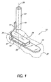
- the prosthetic foot 10 generally comprises a lower foot plate 12, an upper, smaller ankle plate 14, an ankle layer or block 16 made of resilient material, connecting the foot plate 12 to the ankle plate 14, and a spring element 18 embedded within the ankle block 16.
- the foot plate 12 has a length and width roughly equal to the approximate length and width of the particular wearer's amputated foot and sized to fit within an outer, flexible cosmesis 30, shown in phantom.
- the ankle plate 14 and the resilient ankle block 16 have approximately the same horizontal cross-sectional size.
- the ankle plate 14, ankle block 16, and spring element 18 are centered transversely with respect to and are generally positioned over the back half of the foot plate 12.
- the ankle block 16 is sandwiched between the foot plate 12 and the ankle plate 14 and is preferably glued or bonded to both plates using polyurethane adhesive or other known securement technologies.
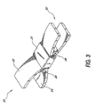
- the spring element 18 is a resilient support member inserted within the resilient ankle block 16. As shown in FIGURE 3 , the spring element 18 is preferably comprised of upper and lower plate-like members 22 and 24, each of which is relatively flat and has a substantially rectangular vertical projection. These members are secured at their center by a fastener 26 and separated at ends 80 and 82.
- the upper member 22 preferably has a curvilinear concave upward shape, while the lower member 24 preferably has a curvilinear concave downward shape. This gives the spring element 18 a substantially double wishbone or bowtie shape.
- the spring element 18 is completely embedded within the ankle block 16 so as not to be visible from the outside.
- the spring element 18 extends substantially longitudinally across the length of the ankle block 16, and has a width substantially equal to the width of ankle block 16.
- the fastener 26 may comprise bolts, a weld, or any other fastening means as would be known to those skilled in the art.
- the fastener 26 is a strap which is laminated around the center portion of the two members 22, 24.
- a wedge member 28, preferably of a resilient elastomer, is placed between the two plate members 22, 24 to protect the inner surfaces of the members and to provide additional support to the spring element 18.
- the wedge 28 acts to provide leverage between the two plate members 22, 24, and enables adjustment of the flexing characteristics of the spring element 18, if desired. Alternatively, it may be bonded permanently in place or formed integrally with one or both of the plate members 22, 24, as desired.
- the spring element 18 has been described as having a double wishbone or bowtie configuration, other shapes and sizes may be appropriate for providing support to the ankle block 16. Furthermore, more than one spring element may be provided in the ankle block to provide support and energy return to the prosthetic foot 10.
- the prosthetic foot 10 further comprises a pylon member 32 which can be secured to the stump of the amputee (not shown) and extends relatively downward therefrom in a generally vertical direction.
- the pylon member 32 in the preferred embodiment is of tubular construction having a substantially equal moment of inertia in all directions to restrict bending in all directions.
- the tubular member 32 is also preferably hollow so that it is relatively light in weight and utilizes less material which reduces the cost of production.
- the pylon member 32 is dimensioned so as to be interchangeable with a standard 30 mm pylon.
- a centerline 70 through pylon 32, shown in FIGURE 1 defines the downward direction of the application of force.
- the ankle plate 14 is secured to the pylon member 32 through a vertically oriented upper attachment member 34.
- the upper attachment member 34 is attached to a curvilinear ankle section 36, which is connected to the ankle plate 14.
- these three pieces are monolithically formed with one another for optimum strength and durability.
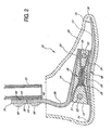
- the attachment member 34 has a rearward surface 38, as shown in FIGURE 2 , and a forward surface 40 substantially parallel thereto.
- the attachment member 34 is substantially rigid and capable of sustaining torsional, impact and other loads impressed thereupon by the prosthesis.
- the inherent rigidity of attachment member 34 prevents it from being distorted in any substantial way and causes the effective transmission of the aforesaid loads imposed thereupon to a suitable ancillary prosthetic pylon 32.
- the attachment member 34 is in the preferred embodiment vertically oriented so that it may be secured to the pylon member 32.
- a coupling device 42 is positioned at the lower end of the pylon member 32 which provides a flat surface upon which the vertical attachment member 34 can be secured.
- the coupling device 42 has one attachment surface 44 which mates with the cylindrical outer surface of the pylon member 32 and a second substantially flat attachment surface 46 which mates with the attachment member 34.
- attachment surface 44 is curved to mate with the outer surface of the tubular pylon member 32, and attachment surface 46 is flat to accommodate the forward surface 40 of the attachment member 34.
- the coupling device 42 is welded or bonded to the pylon member 32 and has two holes (not shown) into which two bolts 48 can be inserted and secured.
- the attachment member 34 also has two holes (not shown) which align with the holes on the coupling device to place and secure the two bolts 48 through the attachment member 34 and the coupling device 42.
- Other methods of securing the pylon member to the foot portion are contemplated, such as those disclosed in my prior issued U.S. Patent No. 5,514,186 , as well as those utilizing integrally formed constructions.
- the attachment member 34 monolithically formed with the ankle plate 14 is vertically aligned so that it extends relatively downward from the coupling device 42 on the pylon member 32. As shown in FIGURE 2 , the thickness of the attachment member 34 along this vertical section is relatively greater than the thickness of the ankle plate 14 substantially horizontally aligned along the foot portion.
- the attachment member 34 is also made relatively thicker to support the vertical load imposed on the prosthetic device as well as to restrict undue bending at this juncture.
- the entire upper vertically-aligned section of attachment member 34 is preferably of substantially uniform thickness and width.
- the tubular pylon member 32 is preferably removable from the prosthetic device such that the pylon member can be replaced without replacing the remainder of the prosthetic device.
- the tubular member of Applicant's invention can be cut and adapted for use by amputees having different stump lengths including growing amputees.
- the prosthetist merely needs to cut a standard tubular pylon to the appropriate length.
- this eliminates the need to manufacture as a part of the prosthesis a long rigid leg section. Thus, fewer materials are needed to manufacture the prosthesis resulting in reduced manufacturing costs.
- the preferred embodiment further comprises cylindrical slots or openings 50, 51 in the fore and aft portions of the ankle block 16, respectively, as shown in FIGURE 2 , to accommodate insertion of stiffeners 52, 53.
- the cylindrical openings 50, 51 are disposed horizontally in a direction generally transverse to a forward walking motion, and between upper and lower plate members 22 and 24.
- Stiffeners 52, 53 can be removably placed in these openings to provide additional support and rigidity to the prosthetic foot 10, and also to modify the spring characteristics of the prosthetic foot. For instance, additional energy storage and return can be provided for a more active amputee by inserting stiffeners 52, 53 into ankle block 16 having a higher spring constant.
- stiffeners with a lower spring constant may be inserted to produce an ankle block 16 with greater dampening characteristics.
- the cylindrical openings 50, 51 may remain empty, thereby making the compliance characteristics dependent solely on the ankle block 16 and the spring element 18.
- Both the foot plate 12 and the ankle plate 14 are preferably formed of a flexible material so that flexing of the plates tends to relieve extreme shear stresses applied to the interfaces between the ankle block 16 and the plates 12, 14.
- Both the foot plate 12 and the ankle plate 14 are preferably constructed of fiberglass which provides strength and flexibility.
- the preferred material for the ankle plate 14 and the foot plate 12 is a vinyl ester based sheet molding compound, such as Quantum #QC-8800, available from Quantum Composites of Midland, Michigan.
- the plates may be formed by a plurality of lamina embedded in an hardened flexible polymer. In other arrangements, the plates may be formed of other materials such as carbon fiber composites as may be apparent to one skilled in the art.
- the desirable properties of the plates are that they are relatively resilient so as to withstand cracking upon application of repeated bending stresses yet have sufficient flexibility to enhance the performance characteristics felt by the wearer in conjunction with the properties of the resilient ankle block.
- the pylon member 32 is preferably made of a stiff material such as a laminate of fiber reinforced composite. Stiffness in the pylon member 32 can also be provided by a stiffer and more dense material.
- the ankle block 16 is sandwiched between the foot plate 12 and the ankle plate 14 as shown in FIGURES 1 and 2 and is preferably bonded to both plates.
- the ankle block is preferably formed of urethane, rubber or other suitable material having desired compliance and energy return characteristics.
- a preferred material for the ankle block is expanded polyurethane foam such as cellular Vulkolka ® Pur-Cell. No. 15-50, with a density of approximately 500 kg/m 3 as available from Pleiger Plastics Company of Washington, Pennsylvania.
- the ankle block 16 may be molded or fabricated from a wide variety of other resilient materials as desired, such as natural or synthetic rubber, plastics, honeycomb structures or other materials.
- Cellular foam provides a high level of compressibility with desirable visco-elastic springiness for a more natural feeling stride without the stiffness drawbacks and limited compression associated with solid elastomeric materials. Furthermore, the cellular nature of a foam block makes it lighter than solid elastomers. Foam densities between about 150 and 1500 kg/m 3 may be used to obtain the benefits of the invention taught herein.
- the spring element 18 is preferably made from a highly resilient material that is capable of supporting compression during relative angular rotation of the upper and lower members 12 and 14, such as during toe and heel roll, and also vertical compression such as in response to vertical shock loads.
- a highly resilient material is carbon fiber composites such as woven fiber mats and chopped fiber in an epoxy matrix.
- carbon fiber composites such as woven fiber mats and chopped fiber in an epoxy matrix.
- other materials with similar strength and weight characteristics will be known to those skilled in the art and may be used with efficacy.
- other filament types may be used, such as glass, Kevlar and nylon by way of example, to ensure lightweight and structural and dynamic characteristics consistent with the needs of a particular amputee.
- the wedge 28 may be fabricated from a wide variety of resilient materials, including natural and synthetic rubber, elastomeric polyurethane, or the like.
- the ankle block 16 containing spring element 18 may be fabricated by injecting a polyurethane elastomer into a mold allowing it to cure.
- the spring element 18 may be inserted into the mold prior to injection of the polyurethane so that during curing, the polyurethane bonds to the spring member.
- Cylindrical slots or openings 50, 51 for insertion of stiffeners 52, 53 may be provided in ankle block 16 by inserting cylindrical plugs into the block prior to injection of polyurethane. Alternatively, openings may be provided in the block after curing simply by cutting or drilling away portions of the ankle block.
- the stiffeners provided in the openings are preferably tubes of foam material having a density chosen according to desired compliance characteristics.
- a preferable material is expanded polyurethane having a foam density between about 150 and 1500 kg/m 3 . More preferably, a density of about 250 to 750 kg/m 3 is preferred to provide adequate adjustment of the energy storage and return characteristics of the foot.
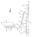
- the foot plate 12 is preferably of curvilinear shape.
- the thickness t of foot plate 12 is preferably tapered along its length, and the tapered profile corresponds approximately to the weight of the amputee. That is, for a heavier amputee, the thicknesses along the length would be greater than for a lighter weight amputee.
- the weight groups may be classified as light, medium, or heavy.
- Table I below presents preferred groupings, as module sizes C/D/E, of cosmesis sizes corresponding to a male "A" width shoe last. The sizes are presented by length L, width B at the forefoot and width H at the heel of the cosmesis. Table I. Cosmesis Sizes for Male "A" Width Shoe Last MODULE LENGTH L (cm) WIDTH B (cm) WIDTH H (cm) C 22 2.88 2.19 23 3.00 2.25 24 3.12 2.31 D 25 3.25 2.44 26 3.38 2.50 27 3.50 2.56 E 28 3.62 2.69 29 3.75 2.75 30 3.88 2.81
- Table II below presents preferred module sizes for various weight groups of amputees.
- Table II. Modules vs. Weight Groups MODULE WEIGHT GROUP LIGHT MEDIUM HEAVY C CL CM - D DL DM DH E - EM EH
- Taper Thickness t for DM Foot Plate POSITION (x 2.54 cm)
- THICKNESS t (cm) a 0.16 b 0.16 c 0.32 d 0.52 e 0.69 f 0.78 g 0.71 h 0.60 i 0.48 j 0.28
- the foot plate 12 has a heel end 54, toward the left in FIGURE 4 , which is concave-upward or slightly uplifted from a horizontal plane P 1 tangential to the heel end 54 of the foot plate 12.
- a toe end 56 to the right of FIGURE 4 , is concave upward or somewhat uplifted from a horizontal plane P 2 tangential to the front portion of the foot plate 12.
- An arch section 58 is formed between the heel and toe ends and is preferably concave-downward, as shown.
- the tangent plane P 1 of the heel end 54 is slightly raised a distance y relative to the tangent plane P 2 of the toe end 56, as shown.
- the foot plate 12 is preferably 0.25 inches (0.63 cm) from the bottom or sole of the cosmesis 30.
- the cosmesis 30 may be insert molded using an anatomically sculpted foot shape, with details and sizing based on a master pattern and/or digitized data representing typical foot sizes.
- An intermediate region 58 comprising the arch portion of the foot plate 12 has the greatest thickness of the foot plate 12.
- the curvature of the arch region 58 is defined by the cosmesis or shoe sole profile, and generally corresponds to selected ranges of human foot lengths.
- the foot plate 12 of prosthesis 10 preferably has a length between about 5 and 15 inches (about 13 and 38 cm), more preferably between about 8 and 12 inches (about 20 and 30 cm) for the foot sizes given in Table I.
- the width of foot plate 12 is preferably about 1 to 4 inches (about 2.5 to 8 cm).
- the length of the plate 12 is approximately 9 inches (about 23 cm) and its width is about 2 inches (about 5 cm).
- the foot plate 12 has a thickness between about 0.05 and 0.4 inches (about 0.1 and 1 cm), which more preferably may be tapered as indicated in Table III.
- the ankle plate 14 of prosthesis 10 is substantially planar, and is preferably shorter in length than the foot plate 12 and has a thickness also defined by the weight group of the wearer.
- the thickness of the ankle plate is preferably about 0.05 to 0.4 inches (0.1 to 1 cm). More preferably, the corresponding ankle plate 14 in the present example is about 0.2 inches (about 0.5 cm) thick at rear portion 62, tapering to a thickness of about 0.1 inches (about 0.25 cm) at front portion 60.
- the ankle plate 14 preferably has a length of about 3 to 7 inches (about 8 to 18 cm) and a width of about 1 to 3 inches (about 2.5 to 8 cm), more preferably having length-width dimension of approximately 5 x 2 inches (about 13 x 5 cm).
- the ankle plate 14 is positioned at an angle such that its front tip 60 is located closer to the foot plate 12 than its rear tip 68. Relative to plane P 3 shown in FIGURE 4 , the rear tip is preferably raised an angle ⁇ of about 5 to 30 degrees, and more preferably, about 10 degrees.
- the ankle block 16 is generally sized such that its upper surface is planar and corresponds to the length and width of the ankle plate 14.
- the lower surface of the ankle block 16 is substantially curvilinear to mate with the curvilinear surface of foot plate 12.
- the block 16 has a preferred thickness, at its front 66, of about 1 to 3 inches (about 2.5 to 8 cm), more preferably about 1.3 inches (about 3.4 cm). Its thickness tapers to a minimum of about 0.5 to 1 inch (about 1 to 2.54 cm), more preferably about 0.8 inches (about 2 cm) adjacent arch portion 58.
- the rear 64 of the block 16 is preferably about 1 to 4 inches (about 2.5 to 10 cm) thick, more preferably about 2.6 inches (about 6.6 cm) thick, which is about twice the thickness of the front portion 66 of the block 16. This gives the ankle block a substantially wedge shape.
- the greater thickness at the rear of block 16 is provided to impart additional support in the rear portion 64 of the ankle block due to greater compressive forces on the rear of the foot prosthesis caused by off-axis application of force relative to axis 70 during heel strike (see FIGURE 5A ).
- the ankle block 16 may be provided in varying heights or thicknesses, as desired, but is most effective with a thickness of between about 1 and 4 inches (about 2.54 and 10 cm).
- the front portion and rear surfaces of ankle block 16 are preferably angled according to the angle ⁇ defined by the plane P 3 and the ankle plate 14.
- the ankle block has front and rear surfaces which are preferably sloped forward at an angle ⁇ from vertical.
- the ankle block thus provides a relatively stiff, yet flexible ankle region which can be customized for various wearers. Heavier wearers may require a denser resilient material for the ankle block, while lighter wearers may require a less dense material or less thickness.
- the spring element 18 is positioned in the ankle block such that the center of the spring element 18, at the position of fastener 26, is located approximately above the arch portion 58 of foot plate 12.
- the two members 22, 24 of the spring element 18 preferably have a constant thickness of about 0.05 to 0.2 inches (about 0.1 to 0.5 cm).
- the distance between the two members at front end 82, when no load is impressed onto the foot 10, is preferably about 0.5 and 2 inches (about 1 to 5 cm), more preferably about 0.7 inches (about 1.8 cm).
- the distance between members 22 and 24 is about 1 to 3 inches (about 2.5 to 7.5 cm), more preferably about 1.4 inches (about 3.5 cm).
- the rear end 80 of the spring element is compressed.
- the forward end 82 of the spring element is compressed.
- the lengths, widths and thicknesses of the foot plate 12, ankle plate 14, ankle block 16 and spring element 18 may be customized for the wearer according to his/her foot size as well as the approximate weight group of the wearer. Likewise, the material choice and size for these elements may be varied according to the wearer's foot size and weight.
- the cylindrical openings 50, 51 provided in the fore and aft portions of ankle block 16 preferably have a diameter of about 0.1 to 0.4 inches (about 0.25 to 1 cm), and more preferably, about 0.2 inches (about 0.5 cm). While the openings 50 and 51 shown in FIGURE 2 have the same diameter, the diameters of the openings may be different to accommodate different sized stiffeners. For instance, the diameter of opening 51 may be made larger than the diameter of opening 50 to correspond with the greater volume of ankle block 16 in rear portion 64.
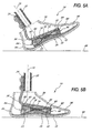
- FIGURES 5A-5D show "snapshots" of a prosthetic foot in several positions of a walking stride. More particularly, FIGURE 5A shows a heel-strike position, FIGURE 5B shows a generally flat or mid-stance position, FIGURE 5C shows a heel-off position, and FIGURE 5D shows a toe-off position.
- the present prosthetic foot 10 provides a smooth and generally life-like response to the wearer.
- the ankle block 16 transmits the forces imparted thereon by the foot plate 12 and ankle plate 14, and experiences a gradual rollover, or migration of the compressed region, from rear to front.
- a first position of a walking stride generally entails a heel strike, wherein the wearer transfers all of his or her weight to the heel of the leading foot.
- a rear portion 54 of the foot plate 12 comes in contact with a ground surface 68, albeit through the cosmesis 30.
- the flexible nature of the foot plate 12 allows it to bend slightly in the rear portion 54, but most of the compressive stresses from the weight of the wearer through the prosthetic foot 10 to the foot plate 12 are absorbed by a rear region 64 of the ankle block 16 with spring element 18.
- the spring element 18 in the rear portion contracts, such that the distance between members 22 and 24 at rear end 80 decreases.
- the spring element 18 may expand slightly such that the distance between members 22 and 24 at front end 82 increases. Front portion 66 of the ankle block 16 experiences a stretching, or tension, due to the attachment along the entire lower edge of the ankle block with the foot plate 12, while rear portion 64 experiences compression. The contraction of the spring element 18 at end 80 and ankle block 16 at end 64 allows the prosthesis 10 to absorb and store energy from the compressive stresses during heel strike. Further, a slight amount of bending may occur in a rear region 68 of the ankle plate 14. The rear stiffener 53 between members 22 and 24 is compressed so as to provide necessary support to the foot prosthesis and to prevent separation of the members 22, 24 from the wedge 28. Front stiffener 52 is slightly stretched substantially vertically due to the tension forces at front portion 66 of ankle block 16.
- the wearer reaches a generally flat-footed or mid-stance position, whereby the foot plate 12 contacts the ground 68 along substantially its entire length, again through the cosmesis 30.
- the weight of the wearer is directed substantially downwardly, so that the compression along the length of the ankle block 16 is only slightly greater in the rear portion 64 than in front portion 66, due to the off-center application of force.
- the members 22 and 24 are compressed towards each other, with the rear end 80 being slightly more compressed from its original position than the forward end 82.
- stiffeners 52 and 53 are compressed due to the downward application of force.
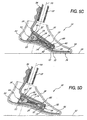
- FIGURE 5C shows the prosthetic foot 10 in a "heel-off" position. This is the instant when the wearer is pushing off using ball 72 and toe 74 regions of the foot.
- a large compressive force is generated in the front region 66 of the ankle block 16, causing the rear region 64 to experience a large amount of separation or tension.
- the spring element 18 at the rear end 80 expands between the two members 22, 24, while it compresses in the front end 82.
- the front tip 56 of the foot plate 12 may bend substantially to absorb some of the compressive stresses.
- the front tip 60 of the ankle plate 14 may bend somewhat at this point.
- the foot plate 12 and ankle plate 14 are designed to work in conjunction with the resilient ankle block and spring element and provide enhanced dynamic performance. Further, the flexing of the foot plate 12 and ankle plate 14 relieves some of the extreme shear stresses applied to the interfaces between the ankle block 16 and plates, thus increasing the life of the bonds formed therebetween.
- the stiffener 52 located in the front 66 of the ankle block 16 compresses so as to limit compression of front end 82, giving the wearer balance and to prevent separation of the members 22, 24 from the wedge 28. Stiffener 53 extends due to the separation of ankle block 16 in rear portion 64.
- FIGURE 5D a final position of the walking stride is shown, wherein the prosthetic foot 10 remains in contact with the ground 68, but some of the weight of the wearer is being transferred to the opposite foot, which has now moved forward.
- this "toe-off" position there is less bending of the front tip 56 of the foot plate 12 and less compression of the front portion 66 of the ankle block 16 and front end 82 of spring element 18.
- the front tip 60 of the ankle plate 14 may flex a slight amount, depending on the material and thickness utilized.
- the region of highest compression of the ankle block 16 remains at the farthest forward region 66, but it is reduced from the compression level of the heel-off position of FIGURE 5C .
- the rear portion 64 of the ankle block 16 experiences a small amount of tension or spreading.
- the "feel" of the present prosthetic foot is greatly enhanced by the cooperation between the foot plate, ankle plate, ankle block and spring inserts.
- the dynamic response from the prosthetic foot is smooth as the ankle block with spring inserts compresses in different regions.
- the flexing of the ankle and foot plates assist in smoothly transmitting the various bumps and jars found in uneven walking surfaces.
- FIGURE 6 One such alternative embodiment is shown in FIGURE 6 .
- Reference numerals for FIGURE 6 generally correspond to the reference numerals used in FIGURES 1-5D for like elements.
- the prosthetic foot 10 shown in FIGURE 6 generally comprises a lower foot plate 12, an upper, smaller ankle plate 14, an ankle layer or block 16 made of resilient material, connecting the foot plate 12 to the ankle plate 14, and a spring element 18 embedded within the ankle block.
- the foot plate 12 has a length and width roughly equal to the approximate length and width of the particular wearer's amputated foot and sized to fit within an outer, flexible cosmesis 30, shown in phantom.
- the ankle plate 14 has a substantially arcuate curvature extending from the integrally formed attachment member 34 to the front of the ankle plate 14.
- the spring element 18 as illustrated in FIGURE 6 is a resilient support member inserted within the resilient ankle block 16.
- the spring element 18 shown in FIGURE 6 is preferably a plate-like member with a curvilinear concave downward shape and a substantially rectangular vertical projection.
- the spring element 18 is preferably made from a carbon fiber composite material such as described hereinbefore, although other similar materials may be used as well.
- FIGURE 7 illustrates another alternative embodiment
- the prosthetic foot 10 shown in FIGURE 7 generally comprises a lower foot plate 12, an upper, smaller ankle plate 14, and an ankle layer or block 16 made of resilient material, such as solid or foam rubber or polyurethane, and connecting the foot plate 12 to the ankle plate 14.
- the foot plate 12 has a length and width roughly equal to the approximate length and width of the particular wearer's amputated foot and sized to fit within an outer, flexible cosmesis 30, shown in phantom.
- the ankle plate 14 transitions into a substantially arcuate or curved ankle section 36 which is preferably integrally formed between the attachment member 34 and the ankle plate 14.
- FIGURE 8 illustrates yet another alternative embodiment
- the prosthetic foot 10 shown in FIGURE 8 generally comprises a lower foot plate 12, an upper, smaller ankle plate 14, and one or more ankle blocks 16a, 16b made of resilient material, such as solid or foam rubber or polyurethane, and connecting the foot plate 12 to the ankle plate 14.
- the posterior ankle block 16a may have a density or compliance characteristic which is different than that of the anterior ankle block 16b, so as to render it more soft and more compliant, for example, than the anterior ankle block 16b. For instance, this configuration could provide a more compliant heel response during heel strike.
- Ankle blocks 16a, 16b may be formed integrally or separately, as desired or as expedient. Preferably, they are positioned closely adjacent to one another so as to occupy substantially the entire space between the foot plate 12 and the ankle plate 14.
- the foot plate 12 preferably has a length and width roughly equal to the approximate length and width of the particular wearer's amputated foot and sized to fit within an outer, flexible cosmesis 30, shown in phantom.
- the ankle plate 14 transitions into a substantially arcuate or curved ankle section 36 which is preferably integrally formed between the attachment member 34 and the ankle plate 14.
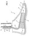
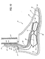
- FIGURES 9 and 10 illustrate two other possible alternative embodiments wherein only Figure 10 discloses the present invention.
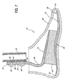
- the prosthetic foot 10 shown in FIGURE 9 generally comprises a lower foot plate 12, an upper, smaller ankle plate 14, and, in this case, an inflatable bladder 19 disposed between the foot plate 12 and the ankle plate 14.
- the bladder 19 has the further advantage in that it enables the patient or prosthetist to vary the performance characteristics of the prosthesis by adjusting the pressure in the bladder 19. This may be accomplished, for example, through the provision of a valve means 21, which is provided in communication with the bladder 19.
- valve 50 is adapted to receive a needle from an air pump (not shown) or from a CO 2 cartridge (not shown), and may be suitably disposed on bracket 27, as illustrated in FIGURES 9 and 10 .
- the valve 21 may be operatively connected to bladder via tubing or other suitable communication passage.
- the bladder 19 may be secured via adhesive or other suitable affixing means to the upper ankle plate 14 and the lower foot plate 12 so as to provide substantially the sole means of connection and support therebetween.
- one or more retaining straps 23 may be used to provide primary or secondary connection support, as needed or desired.
- Strap 23 may be fabricated from any number of suitably tough, flexible materials such as epoxy-impregnated canvas or the like.
- straps 23 may be operatively attached to the forefoot portion of the prosthetic foot 10 as illustrated in FIGURE 9 via adhesive, or nuts and bolts, or may be releasably attached around the structural member 12, 14 through the provision of Velcro ® -type fasteners or similar expedient.
- the straps 23 provide a number of benefits. For example, if juxtaposed to a bladder member 19, the strap may be appropriately tightened to 'flatten' the bladder, thus increasing the contact area between the structural members 12, 14 and the bladder. Moreover, restraining means such as the straps 23 may be incorporated to restrict the distance that the associated structural members 12, 14 may move from one another. The straps 23 may also be utilized to prevent undesirable excessive loading and stressing of the structural members 12, 14 and/or the bladder 19.
- the bladder 19 is preferably fabricated from a suitably strong, flexible, leak-proof, lightweight material such as urethane or the like.
- the bladder may be formed by heat sealing appropriately sized and shaped pieces of urethane sheet to each other.
- Suitable thicknesses of urethane sheet material have been found to be 0.01 to 0.02 inches (0.25 - 0.50 mm), but a wide range of suitable thicknesses and materials may also be utilized with efficacy.
- Bladder pressures of up to 80 psi (5.5 bar) have been utilized with efficacy.
- the bladder 19 is preferably enwrapped in a covering material of Kevlar or similarly strong material to prevent the bladder 19 from exploding under high pressures and to help define the final inflated shape of the bladder.
- a covering may include top and bottom sections which are stitched together at the perimeter 25 of the bladder 19.
- Bladder 19 may enclose air, CO 2 , or a similar gas-like substance, or may alternatively enclose liquids or gels such as water, silicone, or the like. Any such assembly is preferably selected and adjusted to provide the desired deformability and consequent 'cushioning' effect or energy-storing, absorption and release.
- the bladder 19 may comprise a single chamber bladder, as illustrated in FIGURE 9 , or, optionally, it may comprise a multiple chamber bladders with or without venting provided between adjacent chambers.
- the bladder could be bifurcated into anterior and posterior chambers or portions 19a, 19b such that the posterior portion 19a can be adjusted to have a compliance characteristic which is different than that of the anterior portion 19b, so as to render it more soft and more compliant, for example, than the anterior portion. This may be desirable, for instance, to provide a more compliant heel response during heel strike.
- the bladder 19 may be tapered in shape so as to permit operative and proper alignment of the bladder between the ankle plate 14 and the foot plate 12.
- a spring element identical or similar to that illustrated and described above in connection with FIGURES 2-5 , may be provided substantially completely within the bladder 19 ( FIGURE 9 ) so as to provide primary or supplemental support between the foot and ankle plates, as desired.
- the spring element may comprise two relatively flat carbon fiber composite members secured at their middle and separated at their ends. This gives the spring element a preferable shape of a bowtie or double wishbone.
- the combination of the resilient spring element and inflatable bladder provides a smooth and adjustable rollover characteristic from a heel-strike to a toe-off, as desired.
- the foot plate 12 preferably has a length and width roughly equal to the approximate length and width of the particular wearer's amputated foot and sized to fit within an outer, flexible cosmesis 30, shown in phantom. As shown in FIGURES 9 and 10 , the ankle plate 14 transitions into a substantially arcuate or curved ankle section 36 which is preferably integrally formed between the attachment member 34 and the ankle plate 14.
Claims (12)
- Fußprothese mit einer unteren Fußplatte (12) mit einem Fersenabschnitt (54) zur Kontaktherstellung mit einer Bodenoberfläche während eines Fersenauftrittes; einer oberen flexiblen Fußgelenkplatte (14), die im Wesentlichen über der unteren Fußplatte (12) angeordnet ist; und einem kompressiblen Balg (19), der zwischen der oberen flexiblen Fußgelenkplatte (14) und der unteren Fußplatte (12) angeordnet ist,
dadurch gekennzeichnet, dass
der kompressible Balg (19) durch Befestigungsmittel an der oberen flexiblen Fußgelenkplatte (14) und der unteren Fußplatte (12) so befestigt ist, dass der kompressible Balg (19) die einzige Verbindungseinrichtung dazwischen ausbildet. - Fußprothese nach Anspruch 1, wobei die Fußplatte (12) eine Länge angenähert gleich der Länge eines natürlichen menschlichen Fußes aufweist.
- Fußprothese nach Anspruch 1 oder 2, wobei der Balg (19) im Wesentlichen die einzige Unterstützungseinrichtung zwischen der unteren Fußplatte (12) und der oberen flexiblen Fußgelenkplatte (14) bereitstellt.
- Fußprothese nach Anspruch 1, 2 oder 3, wobei die Fußplatte (12) und der Balg (19) sich in einer zusammenwirkenden Weise durchbiegen, um einen im Wesentlichen sanften und kontinuierlichen Abrollübergang von dem Fersenauftritt bis zur Zehenabhebung bereitzustellen.
- Fußprothese nach einem der vorstehenden Ansprüche, wobei die Fußplatte (12) eine sich verjüngende Dicke entlang ihres Längsverlaufs dergestalt aufweist, dass die Dicke von einem Fersenabschnitt (54) zu einem Gewölbeabschnitt (58) hin zunimmt und von dem Gewölbeabschnitt (58) zu einem Zehenabschnitt (56) hin abnimmt.
- Fußprothese nach einem der vorstehenden Ansprüche, wobei der Balg (19) aus Urethan besteht.
- Fußprothese nach einem der vorstehenden Ansprüche, wobei der Balg (19) eine Wanddicke zwischen 0,25 und 0,5 mm aufweist.
- Fußprothese nach einem der vorstehenden Ansprüche, wobei der Balg (19) Luft, Kohlendioxid, Flüssigkeiten oder Gele einschließt.
- Fußprothese nach einem der vorstehenden Ansprüche, wobei der Balg (19) Luft einschließt.
- Fußprothese nach einem der vorstehenden Ansprüche, wobei der Balg (19) zwei oder mehr Kammern (19a, 19b) aufweist, und wobei wenigstens eine von den Kammern so angepasst werden kann, dass sie eine Nachgiebigkeit aufweist, die sich von der Nachgiebigkeit der wenigstens einen weiteren Kammer unterscheidet.
- Fußprothese nach einem der vorstehenden Ansprüche, wobei die untere Fußplatte (12) und die obere flexible Fußgelenkplatte (14) sich einander nicht direkt berühren.
- Fußprothese nach einem der vorstehenden Ansprüche, wobei eine Oberseite des Balgs (19) an einer Unterseite der
oberen flexiblen Fußgelenkplatte (14) befestigt ist, und eine Unterseite des Balgs (19) an einer Oberseite der unteren Fußplatte (12) befestigt ist.
Applications Claiming Priority (5)
| Application Number | Priority Date | Filing Date | Title |
|---|---|---|---|
| US8147298P | 1998-04-10 | 1998-04-10 | |
| US81472P | 1998-04-10 | ||
| US09/138,357 US6206934B1 (en) | 1998-04-10 | 1998-08-21 | Ankle block with spring inserts |
| US138357 | 1998-08-21 | ||
| EP99919807A EP0988004B1 (de) | 1998-04-10 | 1999-04-09 | Fussprothese mit gefedertem knöchel |
Related Parent Applications (2)
| Application Number | Title | Priority Date | Filing Date |
|---|---|---|---|
| EP99919807.0 Division | 1999-04-09 | ||
| EP99919807A Division EP0988004B1 (de) | 1998-04-10 | 1999-04-09 | Fussprothese mit gefedertem knöchel |
Publications (3)
| Publication Number | Publication Date |
|---|---|
| EP1332737A2 EP1332737A2 (de) | 2003-08-06 |
| EP1332737A3 EP1332737A3 (de) | 2003-10-15 |
| EP1332737B1 true EP1332737B1 (de) | 2008-06-04 |
Family
ID=26765602
Family Applications (2)
| Application Number | Title | Priority Date | Filing Date |
|---|---|---|---|
| EP99919807A Expired - Lifetime EP0988004B1 (de) | 1998-04-10 | 1999-04-09 | Fussprothese mit gefedertem knöchel |
| EP03003285A Expired - Lifetime EP1332737B1 (de) | 1998-04-10 | 1999-04-09 | Fussprothese mit gefedertem Knöchel |
Family Applications Before (1)
| Application Number | Title | Priority Date | Filing Date |
|---|---|---|---|
| EP99919807A Expired - Lifetime EP0988004B1 (de) | 1998-04-10 | 1999-04-09 | Fussprothese mit gefedertem knöchel |
Country Status (13)
| Country | Link |
|---|---|
| US (6) | US6206934B1 (de) |
| EP (2) | EP0988004B1 (de) |
| JP (2) | JP4307572B2 (de) |
| KR (1) | KR20010013639A (de) |
| AT (2) | ATE397429T1 (de) |
| AU (1) | AU743488B2 (de) |
| BR (1) | BR9906349A (de) |
| CA (1) | CA2293486C (de) |
| DE (2) | DE69905830T2 (de) |
| DK (1) | DK0988004T3 (de) |
| ES (1) | ES2192844T3 (de) |
| PT (1) | PT988004E (de) |
| WO (1) | WO1999052476A1 (de) |
Families Citing this family (162)
| Publication number | Priority date | Publication date | Assignee | Title |
|---|---|---|---|---|
| US6206934B1 (en) * | 1998-04-10 | 2001-03-27 | Flex-Foot, Inc. | Ankle block with spring inserts |
| US6899737B1 (en) * | 1998-04-10 | 2005-05-31 | Van L. Phillips | Foot prosthesis having cushioned ankle |
| GB2348813A (en) * | 1999-04-16 | 2000-10-18 | Vessa Ltd | Prosthetic foot |
| US6398818B1 (en) * | 1999-07-02 | 2002-06-04 | Crp, Inc. | Lower leg prosthesis |
| KR100362736B1 (ko) * | 2000-04-03 | 2002-12-28 | 한국과학기술원 | 에너지 저장형 의족용골 |
| GB2361645A (en) * | 2000-04-26 | 2001-10-31 | Blatchford & Sons Ltd | Prosthetic foot |
| US7044984B2 (en) * | 2000-04-26 | 2006-05-16 | Rehabilitation Institute Of Chicago | High profile multiaxial prosthetic foot |
| US7341603B2 (en) * | 2000-06-30 | 2008-03-11 | Applied Composite Technology, Inc. | Prosthetic foot with energy transfer including variable orifice |
| US20050216098A1 (en) * | 2000-06-30 | 2005-09-29 | Roland J. Christensen | Variable resistance cell |
| US7686848B2 (en) * | 2000-06-30 | 2010-03-30 | Freedom Innovations, Llc | Prosthetic foot with energy transfer |
| US6875241B2 (en) | 2000-06-30 | 2005-04-05 | Roland J. Christensen, As Operating Manager Of Rjc Development Lc, General Partner Of The Roland J. Christensen Family Limited Partnership | Variable resistance cell |
| WO2002002034A1 (en) | 2000-06-30 | 2002-01-10 | Roland J. Christensen, As Operating Manager Of Rjc Development, Lc, General Partner Of The Roland J. Christensen Family Limited Partnership | Prosthetic foot |
| US7572299B2 (en) * | 2000-06-30 | 2009-08-11 | Freedom Innovations, Llc | Prosthetic foot with energy transfer |
| US20060241783A1 (en) * | 2000-06-30 | 2006-10-26 | Christensen Roland J | Variable resistance cell |
| DE60142451D1 (de) | 2000-10-26 | 2010-08-05 | Ossur North America Inc | Fussprothese mit gefedertem knöchel |
| CA2432681A1 (en) * | 2000-12-22 | 2002-07-04 | Barry. W. Townsend | Prosthetic foot |
| US6562075B2 (en) * | 2001-03-30 | 2003-05-13 | Barry W. Townsend | Prosthetic foot with tunable performance |
| US7611543B2 (en) | 2001-03-30 | 2009-11-03 | Bioquest Prosthetics, Llc | Prosthetic foot with tunable performance |
| US7108723B2 (en) * | 2000-12-22 | 2006-09-19 | Townsend Barry W | Prosthetic foot |
| US7410503B2 (en) * | 2001-03-30 | 2008-08-12 | Bioquest Prosthetics Llc | Prosthetic foot with tunable performance |
| US6712860B2 (en) * | 2001-02-09 | 2004-03-30 | Otto Bock Healthcare Lp | Lower leg prosthesis |
| US7374578B2 (en) | 2001-03-30 | 2008-05-20 | Bioquest Prosthetics, Llc | Prosthetic foot with tunable performance |
| US20060185703A1 (en) * | 2001-03-30 | 2006-08-24 | Townsend Barry W | Mobility assistance apparatus |
| US7429272B2 (en) * | 2001-03-30 | 2008-09-30 | Bioquest Prosthetics Llc | Prosthetic foot with tunable performance |
| US20070213841A1 (en) * | 2001-03-30 | 2007-09-13 | Townsend Barry W | Prosthetic foot with tunable performance |
| US8070829B2 (en) * | 2003-09-30 | 2011-12-06 | Bioquest Prosthetics Llc | Prosthetic foot with tunable performance |
| US8236062B2 (en) | 2001-03-30 | 2012-08-07 | Bioquest Prosthetics Llc | Prosthetic foot with tunable performance |
| US7507259B2 (en) * | 2001-03-30 | 2009-03-24 | Bioquest Prosthetics, Llc | Prosthetic foot with tunable performance |
| US7578852B2 (en) * | 2001-03-30 | 2009-08-25 | Bioquest Prosthetics, Llc | Prosthetic foot with tunable performance and improved vertical load/shock absorption |
| US7954502B2 (en) | 2001-03-30 | 2011-06-07 | Bioquest Prosthetics, Llc | Mobility assistance apparatus |
| JP4733317B2 (ja) * | 2001-08-28 | 2011-07-27 | 本田技研工業株式会社 | 脚式歩行ロボットの床反力検出器 |
| US6702858B2 (en) | 2002-05-15 | 2004-03-09 | Roland J. Christensen | Liner for prosthetic socket with variable viscosity fluid |
| US20040064195A1 (en) | 2002-07-15 | 2004-04-01 | Hugh Herr | Variable-mechanical-impedance artificial legs |
| KR100690909B1 (ko) * | 2002-08-22 | 2007-03-09 | 빅톰 휴먼 바이오닉스 인크. | 무릎-이상 절단자용 작동 의족 |
| US6706075B1 (en) * | 2002-08-22 | 2004-03-16 | Aldo A. Laghi | Dynamic prosthetic foot with multiple load points having sole only |
| US6702859B1 (en) * | 2002-08-22 | 2004-03-09 | Aldo A. Laghi | Dynamic prosthetic foot with multiple load points and anterior/posterior upper sections |
| US6805717B2 (en) | 2002-10-08 | 2004-10-19 | Roland J. Christensen, As Operating Manager Of Rjc Development, Lc, General Manager Of The Roland J. Christensen Family Limited Partnership | Energy-storing prosthetic foot with elongated forefoot |
| US6929665B2 (en) * | 2002-10-08 | 2005-08-16 | Roland J. Christensen | Prosthetic foot with a resilient ankle |
| US6911052B2 (en) | 2002-10-08 | 2005-06-28 | Roland J. Christensen, As Operating Manager Of Rjc Development, Lc, General Partner Of The Roland J. Christensen Family Limited Partnership | Prosthetic foot with oblique attachment |
| US7419509B2 (en) * | 2002-10-08 | 2008-09-02 | Freedom Innovations, Llc | Prosthetic foot with a resilient ankle |
| US8007544B2 (en) | 2003-08-15 | 2011-08-30 | Ossur Hf | Low profile prosthetic foot |
| US20050060045A1 (en) * | 2003-09-16 | 2005-03-17 | Smith Nolan L. | Multi-axial prosthetic foot |
| US8075633B2 (en) | 2003-09-25 | 2011-12-13 | Massachusetts Institute Of Technology | Active ankle foot orthosis |
| US8574314B2 (en) * | 2003-09-30 | 2013-11-05 | Bioquest Prosthetics Llc | Resilient prosthetic and orthotic components which incorporate a plurality of sagittally oriented struts |
| US6966933B2 (en) * | 2003-10-21 | 2005-11-22 | Roland J. Christensen, As Operating Manager Of Rjc Development, Lc, General Partner Of The Roland J. Christensen Family Limited Partnership | Prosthetic foot with an adjustable ankle and method |
| US7520904B2 (en) * | 2003-10-21 | 2009-04-21 | Freedom Innovations, Llc | Prosthetic foot with an adjustable ankle and method |
| US7815689B2 (en) | 2003-11-18 | 2010-10-19 | Victhom Human Bionics Inc. | Instrumented prosthetic foot |
| US20050107889A1 (en) | 2003-11-18 | 2005-05-19 | Stephane Bedard | Instrumented prosthetic foot |
| US20060184280A1 (en) * | 2005-02-16 | 2006-08-17 | Magnus Oddsson | System and method of synchronizing mechatronic devices |
| US7637959B2 (en) * | 2004-02-12 | 2009-12-29 | össur hf | Systems and methods for adjusting the angle of a prosthetic ankle based on a measured surface angle |
| AU2005215769B2 (en) * | 2004-02-12 | 2012-01-19 | Ossur Hf. | System and method for motion-controlled foot unit |
| US7172630B2 (en) * | 2004-02-20 | 2007-02-06 | Roland J. Christensen, As Operating Manager Of Rjc Development, Lc, General Partner Of The Roland J. Christensen Family Limited Partnership | Prosthetic foot with cam |
| WO2005087144A2 (en) * | 2004-03-10 | 2005-09-22 | össur hf | Control system and method for a prosthetic knee |
| US20050283257A1 (en) * | 2004-03-10 | 2005-12-22 | Bisbee Charles R Iii | Control system and method for a prosthetic knee |
| WO2005089683A2 (en) * | 2004-03-16 | 2005-09-29 | Tensegrity Prosthetics, Inc. | Tensegrity joints for prosthetic, orthotic, and robotic devices |
| JP2007530237A (ja) * | 2004-04-01 | 2007-11-01 | ダブリュ タウンゼンド、バリー | 機能調整式義足 |
| WO2005112838A2 (en) * | 2004-05-19 | 2005-12-01 | Otto Bock Healthcare Lp | Multi-axial fitting with shock absorption for prosthetic foot |
| US7581454B2 (en) * | 2004-05-28 | 2009-09-01 | össur hf | Method of measuring the performance of a prosthetic foot |
| US8128709B2 (en) * | 2004-05-28 | 2012-03-06 | össur hf | Functional foot cover |
| US7347877B2 (en) | 2004-05-28 | 2008-03-25 | össur hf | Foot prosthesis with resilient multi-axial ankle |
| US7542876B2 (en) * | 2004-06-25 | 2009-06-02 | Johnson Controls Technology Company | Method of and apparatus for evaluating the performance of a control system |
| US7219443B2 (en) * | 2004-12-07 | 2007-05-22 | Eric Czaplewski | Protective booties and leggings |
| EP1848380B1 (de) * | 2004-12-22 | 2015-04-15 | Össur hf | Systeme und verfahren zur bearbeitung der gliedmassenbewegung |
| EP1845906A1 (de) * | 2005-01-25 | 2007-10-24 | College Park Industries, Inc. | Submalleolare nichtgelenkige fussprothese mit erhöhter dorsiflexion |
| EP1843823B1 (de) | 2005-02-02 | 2016-10-26 | Össur hf | Prothetische und orthetische rehabilitationsysteme |
| US8801802B2 (en) * | 2005-02-16 | 2014-08-12 | össur hf | System and method for data communication with a mechatronic device |
| US20070043449A1 (en) | 2005-03-31 | 2007-02-22 | Massachusetts Institute Of Technology | Artificial ankle-foot system with spring, variable-damping, and series-elastic actuator components |
| US10307272B2 (en) | 2005-03-31 | 2019-06-04 | Massachusetts Institute Of Technology | Method for using a model-based controller for a robotic leg |
| US20060249315A1 (en) | 2005-03-31 | 2006-11-09 | Massachusetts Institute Of Technology | Artificial human limbs and joints employing actuators, springs, and variable-damper elements |
| US10080672B2 (en) * | 2005-03-31 | 2018-09-25 | Bionx Medical Technologies, Inc. | Hybrid terrain-adaptive lower-extremity systems |
| US8864846B2 (en) * | 2005-03-31 | 2014-10-21 | Massachusetts Institute Of Technology | Model-based neuromechanical controller for a robotic leg |
| US20070162152A1 (en) * | 2005-03-31 | 2007-07-12 | Massachusetts Institute Of Technology | Artificial joints using agonist-antagonist actuators |
| US20070123997A1 (en) * | 2005-03-31 | 2007-05-31 | Massachusetts Institute Of Technology | Exoskeletons for running and walking |
| US8512415B2 (en) | 2005-03-31 | 2013-08-20 | Massachusetts Institute Of Technology | Powered ankle-foot prothesis |
| US8500823B2 (en) | 2005-03-31 | 2013-08-06 | Massachusetts Institute Of Technology | Powered artificial knee with agonist-antagonist actuation |
| US11278433B2 (en) | 2005-03-31 | 2022-03-22 | Massachusetts Institute Of Technology | Powered ankle-foot prosthesis |
| SE528516C2 (sv) | 2005-04-19 | 2006-12-05 | Lisa Gramnaes | Kombinerat aktivt och passivt benprotessystem samt en metod för att utföra en rörelsecykel med ett sådant system |
| CN101453964B (zh) | 2005-09-01 | 2013-06-12 | 奥瑟Hf公司 | 用于确定地形转换的系统和方法 |
| US7531006B2 (en) * | 2005-09-01 | 2009-05-12 | össur hf | Sensing system and method for motion-controlled foot unit |
| US8048172B2 (en) * | 2005-09-01 | 2011-11-01 | össur hf | Actuator assembly for prosthetic or orthotic joint |
| DE102005061266A1 (de) * | 2005-12-20 | 2007-08-16 | Otto Bock Healthcare Ip Gmbh & Co. Kg | Handprothese sowie Kraftübertragungseinrichtung |
| DE102006004132B4 (de) * | 2006-01-27 | 2019-04-25 | Ottobock Se & Co. Kgaa | Künstlicher Fuß und Verfahren zur Steuerung der Bewegung eines künstlichen Fußes |
| US7503937B2 (en) * | 2006-07-03 | 2009-03-17 | Ossur Hf | Prosthetic foot |
| US7618464B2 (en) * | 2006-08-03 | 2009-11-17 | Freedom Innovations, Llc | Prosthetic foot with variable medial/lateral stiffness |
| US7824446B2 (en) * | 2006-12-06 | 2010-11-02 | Freedom Innovations, Llc | Prosthetic foot with longer upper forefoot and shorter lower forefoot |
| US9259332B2 (en) * | 2006-12-14 | 2016-02-16 | Lincolnshire Manufacturing, Llc | Prosthetic vacuum system |
| US7727285B2 (en) * | 2007-01-30 | 2010-06-01 | Freedom Innovations, Llc | Prosthetic foot with variable medial/lateral stiffness |
| US7603192B2 (en) * | 2007-02-13 | 2009-10-13 | Orthohelix Surgical Designs, Inc. | Method of making orthopedic implants and the orthopedic implants |
| US7794506B2 (en) * | 2007-09-18 | 2010-09-14 | Freedom Innovations, Llc | Multi-axial prosthetic ankle |
| US10842653B2 (en) | 2007-09-19 | 2020-11-24 | Ability Dynamics, Llc | Vacuum system for a prosthetic foot |
| US7766974B2 (en) * | 2007-10-19 | 2010-08-03 | American Prosthetic Components, Inc. | Prosthetic foot with a processor to manage energy return of adjustable heel and keel springs |
| US7763082B1 (en) * | 2007-10-19 | 2010-07-27 | American Prosthetic Components, Inc. | Prosthetic foot with heel and keel springs |
| US20090119845A1 (en) * | 2007-11-12 | 2009-05-14 | Joel Bastien | Inflatable extremity elevation device |
| US20090204037A1 (en) * | 2008-02-12 | 2009-08-13 | Sundaram Ravikumar | Compression Apparatus for Applying Intermittent Pressure to the Leg |
| US8118879B2 (en) * | 2008-03-14 | 2012-02-21 | Wilson Michael T | Prosthetic foot with flexible ankle portion |
| WO2009120637A1 (en) | 2008-03-24 | 2009-10-01 | Ossur Hf | Transfemoral prosthetic systems and methods for operating the same |
| US8034121B2 (en) * | 2008-04-18 | 2011-10-11 | Freedom Innovations, Llc | Prosthetic foot with two leaf-springs joined at heel and toe |
| US8821589B2 (en) * | 2008-05-13 | 2014-09-02 | Jerome R. Rifkin | Joints for prosthetic, orthotic and/or robotic devices |
| EP2119997B1 (de) * | 2008-05-13 | 2011-12-21 | Hitachi Zosen Inova AG | Verfahren zur Überprüfung einer Klopfvorrichtung |
| US8685109B2 (en) * | 2008-07-01 | 2014-04-01 | össur hf | Smooth rollover insole for prosthetic foot |
| DE602008003563D1 (de) * | 2008-07-07 | 2010-12-30 | Siemens Ag | Direktantriebsgenerator und Windturbine |
| US9011554B2 (en) * | 2008-07-25 | 2015-04-21 | Fillauer Composites Llc | High-performance multi-component prosthetic foot |
| US8317877B2 (en) * | 2008-08-18 | 2012-11-27 | The Ohio Willow Wood Company | Prosthetic foot |
| US20100174384A1 (en) | 2008-09-04 | 2010-07-08 | Iwalk, Inc. | Hybrid terrain-adaptive lower-extremity systems |
| US20110082566A1 (en) * | 2008-09-04 | 2011-04-07 | Herr Hugh M | Implementing a stand-up sequence using a lower-extremity prosthesis or orthosis |
| WO2010110637A1 (es) * | 2009-03-26 | 2010-09-30 | Ramiro Ruiz Cervantes | Dispositivo de rebote para protesis de amputados de miembros inferiores |
| WO2011005482A2 (en) * | 2009-06-22 | 2011-01-13 | University Of Washington | Controllable transverse rotation adaptor |
| US20110015762A1 (en) * | 2009-07-14 | 2011-01-20 | Tensegrity Prosthetics Inc. | Joints for prosthetic, orthotic and/or robotic devices |
| EP2536365A2 (de) * | 2010-02-19 | 2012-12-26 | Tensegrity Prosthetics Inc. | Gelenke für prothesen, orthesen und/oder robotervorrichtungen |
| WO2011106564A1 (en) * | 2010-02-26 | 2011-09-01 | össur hf | Prosthetic foot with a curved split |
| JP2013524880A (ja) | 2010-04-05 | 2013-06-20 | アイウォーク, インコーポレイテッド | プロテーゼまたは装具におけるトルク制御 |
| US8500825B2 (en) | 2010-06-29 | 2013-08-06 | Freedom Innovations, Llc | Prosthetic foot with floating forefoot keel |
| US20120179274A1 (en) * | 2010-07-13 | 2012-07-12 | Christensen Roland J | Bifurcated, multi-purpose prosthetic foot |
| DE102010034893A1 (de) * | 2010-08-19 | 2012-02-23 | Medi Gmbh & Co. Kg | Fußprothese |
| WO2012096956A1 (en) | 2011-01-10 | 2012-07-19 | Iwalk, Inc. | Powered joint orthosis |
| US20120259430A1 (en) | 2011-01-12 | 2012-10-11 | Zhixiu Han | Controlling powered human augmentation devices |
| US9687377B2 (en) | 2011-01-21 | 2017-06-27 | Bionx Medical Technologies, Inc. | Terrain adaptive powered joint orthosis |
| US8721737B2 (en) | 2011-02-03 | 2014-05-13 | Marquette University | Passive ankle prosthesis with energy return simulating that of a natural ankle |
| US8377145B1 (en) * | 2011-03-02 | 2013-02-19 | Kinetic Revolutions, LLC | Adjustable pylon for prosthetic limb |
| WO2012125562A1 (en) | 2011-03-11 | 2012-09-20 | Iwalk, Inc. | Biomimetic joint actuators |
| DE102011014994A1 (de) | 2011-03-23 | 2012-09-27 | Otto Bock Healthcare Gmbh | Prothesenfußeinsatz und Prothesenfuß |
| US9060884B2 (en) | 2011-05-03 | 2015-06-23 | Victhom Human Bionics Inc. | Impedance simulating motion controller for orthotic and prosthetic applications |
| WO2013055462A1 (en) | 2011-09-06 | 2013-04-18 | össur hf | Prosthetic and orthotic devices having magnetorheological elastomer spring with controllable stiffness |
| WO2013067407A1 (en) | 2011-11-02 | 2013-05-10 | Iwalk, Inc. | Biomimetic transfemoral prosthesis |
| US9017421B2 (en) | 2011-12-01 | 2015-04-28 | össur hf | Prosthetic foot with dual foot blades and vertically offset toe |
| US9032635B2 (en) | 2011-12-15 | 2015-05-19 | Massachusetts Institute Of Technology | Physiological measurement device or wearable device interface simulator and method of use |
| US8961618B2 (en) | 2011-12-29 | 2015-02-24 | össur hf | Prosthetic foot with resilient heel |
| US9198780B2 (en) | 2012-02-14 | 2015-12-01 | Ossur Hf | Vacuum assisted suspension system |
| US9017419B1 (en) | 2012-03-09 | 2015-04-28 | össur hf | Linear actuator |
| US9221177B2 (en) | 2012-04-18 | 2015-12-29 | Massachusetts Institute Of Technology | Neuromuscular model-based sensing and control paradigm for a robotic leg |
| US9190886B2 (en) | 2012-04-27 | 2015-11-17 | Sole Power, Llc | Foot-powered energy generator |
| US8970054B2 (en) * | 2012-04-27 | 2015-03-03 | Sole Power, Llc | Foot-powered energy harvesting mechanisms for insoles and shoes |
| WO2013165909A1 (en) | 2012-04-30 | 2013-11-07 | Ossur Hf | Prosthetic device, system and method for increasing vacuum attachment |
| US10531965B2 (en) | 2012-06-12 | 2020-01-14 | Bionx Medical Technologies, Inc. | Prosthetic, orthotic or exoskeleton device |
| US20140012396A1 (en) * | 2012-07-06 | 2014-01-09 | Ossur Hf | Prosthetic foot with hybrid layup |
| KR101421158B1 (ko) | 2012-10-24 | 2014-07-22 | 한국산업기술대학교산학협력단 | 다수의 스프링이 구비된 의족 |
| CN103099690B (zh) * | 2013-02-25 | 2015-08-19 | 西南交通大学 | 一种助力型外骨骼用复合式承载鞋 |
| EP2961355B1 (de) | 2013-02-26 | 2018-08-22 | Össur hf | Fussprothese mit verbesserter stabilität und elastischer energierückspeisung |
| WO2014134381A1 (en) | 2013-03-01 | 2014-09-04 | Ossur Hf | Vacuum suspension system |
| TWI593882B (zh) * | 2013-10-04 | 2017-08-01 | 林哲瑋 | 發電裝置 |
| DE102014006571B3 (de) * | 2014-05-07 | 2015-08-06 | Otto Bock Healthcare Gmbh | Prothesenfuß |
| US9763808B2 (en) | 2014-05-19 | 2017-09-19 | Ossur Hf | Adjustable prosthetic device |
| WO2016004090A1 (en) | 2014-06-30 | 2016-01-07 | össur hf | Prosthetic feet and foot covers |
| US9757256B2 (en) | 2014-07-01 | 2017-09-12 | Ossur Hf | Pump mechanism for vacuum suspension system |
| WO2016022699A1 (en) * | 2014-08-08 | 2016-02-11 | Board Of Regents, The Universitiy Of Texas System | Layering technique for an adjustable, repairable variable stiffness prosthetic foot |
| US10034782B2 (en) | 2014-09-19 | 2018-07-31 | össur hf | Variable stiffness prosthetic foot |
| WO2016109817A1 (en) | 2014-12-31 | 2016-07-07 | Chinook Asia Llc | Footwear having a flex-spring sole |
| US10028845B2 (en) | 2015-01-08 | 2018-07-24 | Ossur Iceland Ehf | Pump mechanism |
| EP3297582B1 (de) | 2015-05-21 | 2019-04-17 | Ossur Iceland EHF | Pumpensystem |
| WO2016196081A1 (en) | 2015-05-29 | 2016-12-08 | Ossur Iceland Ehf | Pump system for use with a prosthetic device |
| USD795433S1 (en) | 2015-06-30 | 2017-08-22 | Össur Iceland Ehf | Prosthetic foot cover |
| WO2017034841A1 (en) | 2015-08-27 | 2017-03-02 | Ossur Iceland Ehf | Pump system |
| WO2017205411A1 (en) * | 2016-05-23 | 2017-11-30 | Icahn School Of Medicine At Mount Sinai | Imaging compatible foot stressor for use in diagnosing foot injuries |
| WO2018039421A1 (en) | 2016-08-26 | 2018-03-01 | Ossur Iceland Ehf | Pump system |
| EP3518834B1 (de) | 2016-12-01 | 2021-08-04 | Össur Iceland EHF | Fussprothese mit einstellbarer fersenhöhe |
| US10980648B1 (en) | 2017-09-15 | 2021-04-20 | Össur Iceland Ehf | Variable stiffness mechanism and limb support device incorporating the same |
| US11446164B1 (en) | 2017-09-15 | 2022-09-20 | Össur Iceland Ehf | Variable stiffness mechanisms |
| USD915596S1 (en) | 2018-04-10 | 2021-04-06 | Össur Iceland Ehf | Prosthetic foot with tapered fasteners |
| WO2019212731A1 (en) | 2018-05-04 | 2019-11-07 | Ossur Iceland Ehf | Spacer unit for use in a movable joint of a prosthetic or orthopedic system |
| US10857008B2 (en) | 2019-03-06 | 2020-12-08 | Impulse Technology LLC | Adapter for self-alignment in 3 dimensional planes for passive prosthetics |
| CN110339547B (zh) * | 2019-07-01 | 2020-11-24 | 军事科学院军事医学研究院环境医学与作业医学研究所 | 一种足部助力外骨骼装置 |
| CN112168438B (zh) * | 2020-08-17 | 2021-06-29 | 吉林大学 | 一种基于气压变化的被动助力柔性仿生拉压体踝足关节假肢 |
Family Cites Families (171)
| Publication number | Priority date | Publication date | Assignee | Title |
|---|---|---|---|---|
| US368580A (en) * | 1887-08-23 | feees | ||
| US1649773A (en) | 1927-11-15 | witmyer | ||
| US56983A (en) | 1866-08-07 | Improvement in artificial legs | ||
| DE363938C (de) | 1922-11-15 | Jaroslav J Pala | Kunstfuss, dessen Fersenteil aus einer Luftkammer aus Gummi besteht | |
| US619731A (en) | 1899-02-21 | Waukee | ||
| DE502698C (de) | 1930-07-16 | Philipp Renner | Kuenstlicher Fuss | |
| US25238A (en) | 1859-08-30 | Artificial leg | ||
| US487697A (en) | 1892-12-06 | Homer f | ||
| US455817A (en) * | 1891-07-14 | Marginal index | ||
| DE379849C (de) | 1923-08-30 | Adolf Schwager | Kuenstlicher Fuss | |
| US534198A (en) * | 1895-02-12 | Artificial leg | ||
| US508034A (en) | 1893-11-07 | Pneumatic sole | ||
| DE322909C (de) | 1920-07-12 | Max Linse | Kuenstliches Bein | |
| DE94444C (de) | ||||
| US57666A (en) * | 1866-09-04 | Improvement in artificial legs | ||
| US561979A (en) | 1896-06-16 | Artificial limb | ||
| US53931A (en) * | 1866-04-10 | 1866-04-10 | Improvement in artificial legs | |
| US809875A (en) * | 1904-06-18 | 1906-01-09 | George E Wilkins | Artificial limb. |
| US817640A (en) | 1905-01-21 | 1906-04-10 | Firm Of Gebrueder Jacob | Automatic gas-igniter. |
| US809876A (en) | 1905-01-28 | 1906-01-09 | George E Wilkins | Artificial limb. |
| US817340A (en) | 1905-03-01 | 1906-04-10 | Rudolf Rosenkranz | Artificial limb. |
| US808296A (en) | 1905-07-21 | 1905-12-26 | Frank W Merrick | Artificial foot. |
| US1056426A (en) | 1912-03-13 | 1913-03-18 | John P Kenny | Pneumatic sole for shoes and boots. |
| US1069001A (en) | 1913-01-14 | 1913-07-29 | William H Guy | Cushioned sole and heel for shoes. |
| GB117547A (en) | 1917-10-20 | 1918-07-25 | Harry Yearsley | Improvements in or applicable to Artificial Legs or Feet. |
| GB120462A (en) * | 1917-11-24 | 1918-11-14 | Paul Schranz | Improvements in and relating to Artificial Feet. |
| GB139936A (en) | 1919-04-28 | 1920-03-18 | Harry Yearsley Junior | Improvements in or applicable to artificial legs or feet |
| DE366553C (de) | 1921-12-13 | 1923-01-06 | Albert Noack | Kuenstliches Fussgelenk |
| DE393281C (de) | 1922-10-04 | 1924-04-07 | Max Benthin | Kuenstlicher Fuss |
| DE392080C (de) | 1923-01-21 | 1924-03-20 | Adolf Rostek | Kuenstlicher Unterschenkel mit anschliessbarem Fuss |
| US1704065A (en) * | 1926-10-25 | 1929-03-05 | Smith Harold Fleming | Artificial foot |
| GB275902A (en) | 1927-04-26 | 1927-08-18 | Adolf Kaletta | Improvements in artificial feet |
| FR661071A (fr) | 1928-09-26 | 1929-07-20 | C Et E Streisguth | Prothèse de pied |
| US2183076A (en) | 1938-09-16 | 1939-12-12 | Joseph Spievak | Artificial ankle joint |
| US2197093A (en) | 1939-01-19 | 1940-04-16 | George Edwards | Artificial foot |
| US2315795A (en) | 1940-06-17 | 1943-04-06 | Conrad B Johnson | Artificial limb |
| US2357893A (en) * | 1943-06-14 | 1944-09-12 | Noel F Harrington | Ankle joint for artificial limbs |
| GB625528A (en) | 1946-04-24 | 1949-06-29 | Thorsten Wallentin Larsson | Foot prosthesis |
| GB621576A (en) | 1946-07-10 | 1949-04-12 | Andre Marcell Desoutter | Improvements in and relating to artificial limbs |
| FR1005124A (fr) | 1947-06-06 | 1952-04-07 | Jambe artificielle | |
| DE811714C (de) | 1948-11-17 | 1951-08-30 | Metallgesellschaft Ag | Gelenkverbaende fuer die beweglichen Teile kuenstlicher Gliedmassen (Prothesen) |
| DE817186C (de) | 1949-03-12 | 1951-10-15 | Metallgesellschaft Ag | Gelenkverbaende fuer Prothesen |
| US2570735A (en) * | 1949-03-18 | 1951-10-09 | Carl A Weise | Flexible joint for artificial limbs |
| US2594945A (en) | 1949-04-27 | 1952-04-29 | Fred C Lucas | Ankle joint for artificial legs |
| DE813191C (de) | 1949-07-15 | 1951-09-10 | Artur Irmscher | Knoechelgelenk fuer kuenstliche Fuesse |
| DE832473C (de) | 1949-08-30 | 1952-04-07 | Leonard Roeser | Kunstglied |
| US2556525A (en) | 1949-10-08 | 1951-06-12 | William M Drennon | Artificial limb joint |
| DE834884C (de) | 1950-05-06 | 1952-03-24 | Anton Schievekamp | Fussprothese |
| DE838480C (de) | 1950-10-18 | 1952-05-08 | Wilhelm Gundermann | Elastisch gelagertes Fussgelenk fuer kuenstliche Beine |
| US2692392A (en) | 1951-04-05 | 1954-10-19 | Modern Limb Supply Co Inc | Artificial limb |
| US2673370A (en) * | 1951-08-17 | 1954-03-30 | Sheetwood Products Company | Method of manufacturing sheet lumber |
| DE924230C (de) | 1952-03-20 | 1955-02-28 | Leonhard Roeser | Kunstglied mit Gelenkausbildung fuer Prothesen-Kunstfuesse |
| US2731645A (en) | 1952-10-20 | 1956-01-24 | Woodall Carl | Ankle joint for artificial limbs |
| DE1754533U (de) | 1954-11-23 | 1957-10-24 | Leonhard Roeser | Prothesenkunstfuss. |
| FR1251230A (fr) | 1957-11-06 | 1961-01-20 | Procédé d'aménagement d'articulation perfectionnée pour appareil de prothèse, notamment pour cheville et articulation en comportant application | |
| FR1213026A (fr) | 1958-10-22 | 1960-03-28 | Proteor Sa | Appareil de prothèse de jambe et son procédé de fabrication |
| US2996295A (en) * | 1959-11-09 | 1961-08-15 | S R Smith Co Inc | Spring end fastener for diving board mount |
| SU137843A1 (ru) | 1959-12-07 | 1960-11-30 | рев Г.А. Дегт | Голеностопный узел протеза нижней конечности |
| US3098239A (en) | 1961-01-18 | 1963-07-23 | Nader Hugo Otto Max | Prosthetic foot |
| DE1174328B (de) | 1963-06-01 | 1964-07-23 | Walther & Cie Ag | Anordnung zum Befahren der Feuergaszuege von Dampferzeugern, in denen nachgeschaltete Beruehrungsheizflaechen an gekuehlten Tragrohren aufgehaengt sind |
| DE1891505U (de) | 1963-12-05 | 1964-04-23 | Felix Kleinekathoefer | Knoechelgelenk fuer fussprothesen. |
| DE1897509U (de) | 1964-04-25 | 1964-07-30 | Juergen Cuntze | Kunstfuss. |
| DE1491182A1 (de) | 1965-11-23 | 1969-07-17 | Kowald Johann Ingo | Kuenstlicher Fuss |
| DE1941762U (de) | 1966-02-28 | 1966-07-07 | Johann Frohn | Allseitig bewegliches knoechelgelenk fuer kunstfuss. |
| DE1954486U (de) | 1966-11-05 | 1967-02-02 | Juergen Cuntze | Kunstfuss. |
| US3551914A (en) | 1968-05-09 | 1971-01-05 | Carl Woodall | Natural action toe lift artificial foot |
| US3671980A (en) * | 1971-02-19 | 1972-06-27 | Lincoln F Baird | Fluid pressure clamp for prosthetic appliance |
| DE2124564C3 (de) | 1971-05-18 | 1981-09-17 | Theodor Dipl.-Kfm. 6900 Heidelberg Trumpler | Unterschenkelprothese |
| US3754286A (en) | 1972-01-21 | 1973-08-28 | M Ryan | Artificial foot having ankle flexible mount |
| US3766569A (en) | 1972-10-05 | 1973-10-23 | J Orange | Artificial foot |
| US3833941A (en) | 1973-02-28 | 1974-09-10 | Wagner S Orthopedic Supply Co | Molded sach foot |
| US3982280A (en) | 1973-05-03 | 1976-09-28 | The United States Of America As Represented By The Secretary Of The Navy | Functional ankle for a prosthetic limb |
| GB1371996A (en) | 1973-05-08 | 1974-10-30 | Blatchford & Sons Ltd | Artificial leg and foot assembly |
| GB1432481A (en) | 1973-05-31 | 1976-04-14 | Hanger & Co Ltd J E | Symes ankle joint |
| DE2442441C3 (de) * | 1974-09-05 | 1978-07-06 | Otto Bock Orthopaedische Industrie Kg, 3428 Duderstadt | Kunstfuß mit Knöchelgelenk |
| SU560606A1 (ru) | 1975-07-18 | 1977-06-05 | Центральный Ордена Трудового Красного Знамени Научно-Исследовательский Институт Протезирования И Протезостроения | Искусственна стопа |
| US3995324A (en) | 1975-09-12 | 1976-12-07 | The United States Of America As Represented By The Administrator Of The National Aeronautics And Space Administration | Actuator device for artificial leg |
| US4051558A (en) * | 1976-06-30 | 1977-10-04 | The United States Of America As Represented By The United States National Aeronautics And Space Administration | Mechanical energy storage device for hip disarticulation |
| US4091472A (en) | 1976-12-27 | 1978-05-30 | Daher Reinhard L | Prosthetic foot |
| SU806023A1 (ru) | 1977-04-21 | 1981-02-23 | Ленинградский Научно-Исследовательскийинститут Протезирования | Искусственна стопа |
| SU778732A1 (ru) | 1977-08-30 | 1980-12-05 | Центральный Ордена Трудового Красного Знамени Научно-Исследовательский Институт Протезирования И Протезостроения | Искусственна стопа |
| SU679208A1 (ru) | 1977-11-03 | 1979-08-15 | Klimov Nikolaj | Искусственна стопа |
| US4177525A (en) | 1977-11-09 | 1979-12-11 | Ohio Willow Wood Co., Inc. | Reinforced artificial foot and method of making |
| US4229839A (en) * | 1977-11-16 | 1980-10-28 | Lord Corporation | Joint prosthesis |
| FR2410998A1 (fr) | 1977-12-08 | 1979-07-06 | Lebre Patrick | Dispositif de reglage pour protheses tubulaires |
| US4225982A (en) | 1978-12-04 | 1980-10-07 | Cochrane Ian W | Molded syme foot with attached stump socket |
| US4360931A (en) | 1979-06-12 | 1982-11-30 | Hampton Ralph C | Prosthetic ankle |
| US4328594A (en) | 1980-02-13 | 1982-05-11 | Campbell John W | Prosthetic foot |
| GB2098072B (en) | 1980-09-25 | 1984-03-21 | Blatchford & Sons Chas A Ltd | Improved endo-skeletal artificial limb |
| US4387472A (en) * | 1980-10-02 | 1983-06-14 | Medical Center Prosthetics, Inc. | Torque absorber with biofeedback |
| US5030239A (en) | 1982-02-12 | 1991-07-09 | Copes, Inc. | Biomechanical ankle |
| US5085665A (en) * | 1982-07-06 | 1992-02-04 | Robert Radocy | Prosthetic device for vigorous activities |
| JPS5932454A (ja) | 1982-08-12 | 1984-02-21 | 高浜 逸郎 | 義足 |
| DE3239959C2 (de) | 1982-10-28 | 1985-08-08 | Heintz, Bruno, 7530 Pforzheim | Knöchelgelenk für eine Beinprothese |
| US4547913A (en) * | 1983-07-11 | 1985-10-22 | Flex Foot, Inc. | Composite prosthetic foot and leg |
| US4555817A (en) | 1983-07-18 | 1985-12-03 | Mckendrick Roderick W | Prosthetic foot and ankle joint |
| US4645509A (en) | 1984-06-11 | 1987-02-24 | Model & Instrument Development Corporation | Prosthetic foot having a cantilever spring keel |
| US5181932A (en) * | 1989-04-13 | 1993-01-26 | Phillips L Van | Foot prosthesis having auxiliary ankle construction |
| GB8605026D0 (en) | 1986-02-28 | 1986-04-09 | Hanger & Co Ltd J E | Artificial foot |
| US4652266A (en) | 1986-03-07 | 1987-03-24 | Kingsley Mfg. Co. | Molded elastomeric prosthetic foot having energy-storing articulated keel |
| US4718913A (en) | 1986-05-27 | 1988-01-12 | Voisin Jerome P | Dual, ankle, springs prosthetic foot and ankle system |
| SU1391643A1 (ru) | 1986-07-24 | 1988-04-30 | Центральный Научно-Исследовательский Институт Протезирования И Протезостроения | Голеностопный узел |
| CA1305585C (en) | 1986-07-28 | 1992-07-28 | Robert E. Arbogast | Prosthetic foot |
| SU1454449A1 (ru) | 1986-11-25 | 1989-01-30 | Центральный Научно-Исследовательский Институт Протезирования И Протезостроения | Протез нижней конечности |
| SU1519588A1 (ru) | 1986-12-29 | 1989-11-07 | Костромская Лесная Опытная Станция | Способ посадки саженцев |
| SE456134B (sv) * | 1987-02-25 | 1988-09-12 | Yngve Ljungblad | Ledanordning vid en fotprotes |
| IT1205023B (it) * | 1987-05-22 | 1989-03-10 | Ciba Geigy Spa | Composti piperidin-triazinici utilizzabili come stabilizzanti di poliolefine |
| US4892554A (en) | 1987-12-21 | 1990-01-09 | Robinson David L | Prosthetic foot |
| DE68914310T2 (de) | 1988-03-04 | 1994-07-14 | Blatchford & Sons Ltd | Beinprothese. |
| US5112356A (en) | 1988-03-04 | 1992-05-12 | Chas A. Blatchford & Sons Limited | Lower limb prosthesis with means for restricting dorsi-flexion |
| DE8804228U1 (de) | 1988-03-29 | 1988-05-05 | Ipos Gmbh & Co Kg, 2120 Lueneburg, De | |
| US5219365A (en) | 1988-03-31 | 1993-06-15 | Sabolich, Inc. | Prosthetic foot |
| US4959073A (en) * | 1988-06-06 | 1990-09-25 | John Merlette | Foot prosthesis and method of making same |
| SU1600759A1 (ru) | 1988-09-20 | 1990-10-23 | Центральный Научно-Исследовательский Институт Протезирования И Протезостроения | Голеностопный узел протеза нижней конечности |
| US5066305A (en) | 1988-10-25 | 1991-11-19 | Model & Instrument Development Corporation | Prosthetic foot having a low profile cantilever spring keel |
| FR2640499A1 (fr) | 1988-12-15 | 1990-06-22 | Palfray Michel | Nouvelle structure de pied prothetique |
| US5290319A (en) * | 1991-02-28 | 1994-03-01 | Phillips L Van | Prosthetic foot incorporating adjustable bladders |
| US5387246A (en) * | 1989-04-13 | 1995-02-07 | Phillips; Van L. | Prosthetic ski leg |
| DE3918810A1 (de) | 1989-06-09 | 1990-12-13 | Bock Orthopaed Ind | Gelenkloser prothesenfuss |
| DE8908356U1 (de) | 1989-07-08 | 1989-11-16 | Ipos Gmbh & Co Kg, 2120 Lueneburg, De | |
| US5139525A (en) * | 1989-07-31 | 1992-08-18 | Kristinsson Oessur | Prosthetic foot |
| US5185570A (en) * | 1990-02-12 | 1993-02-09 | Helmuth J. Katz | Telecommunications signal detector |
| US5019109A (en) | 1990-03-09 | 1991-05-28 | Voisin Jerome P | Multi-axial rotation system for artificial ankle |
| SE469780B (sv) | 1990-04-02 | 1993-09-13 | Finn Gramnaes | Artificiell fot samt användning av en kulskruv och kulmutter vid en dylik fot |
| DE4012718A1 (de) * | 1990-04-21 | 1991-10-24 | Hoechst Ag | Schalungsbahn |
| US5116384A (en) * | 1990-08-31 | 1992-05-26 | Syncor, Ltd. | Prosthetic foot |
| US5376141A (en) * | 1990-09-21 | 1994-12-27 | Phillips; Van L. | Low-profile symes foot prosthesis |
| DE4038063C2 (de) | 1990-11-29 | 1995-04-20 | Bock Orthopaed Ind | Gelenkloser Prothesenfuß |
| US5108456A (en) * | 1991-01-28 | 1992-04-28 | Coonan Iii Thomas J | Prosthetic appliance |
| US5443529A (en) * | 1991-02-28 | 1995-08-22 | Phillips; Van L. | Prosthetic device incorporating multiple sole bladders |
| US5899944A (en) * | 1991-02-28 | 1999-05-04 | Phillips; Van L. | Prosthetic foot incorporating compressible members |
| US5116385A (en) | 1991-05-06 | 1992-05-26 | Universite De Montreal | Medio-lateral control enhancing, cantilever-spring type prosthetic foot |
| US5158570A (en) * | 1991-05-10 | 1992-10-27 | College Park Industries, Inc. | Prosthetic foot with improved ankle and elastomeric heel pad |
| US5258038A (en) | 1991-05-10 | 1993-11-02 | College Park Industries, Inc. | Prosthetic foot with ankle joint and toe member |
| US5701686A (en) | 1991-07-08 | 1997-12-30 | Herr; Hugh M. | Shoe and foot prosthesis with bending beam spring structures |
| US5156631A (en) | 1991-09-16 | 1992-10-20 | John Merlette | Foot and leg prosthesis and method of making same |
| US5258039A (en) | 1991-11-15 | 1993-11-02 | The National University Of Singapore | Energy storing composite prosthetic foot |
| US5376140A (en) | 1992-01-03 | 1994-12-27 | Ryan; Michael W. | Prosthetic foot |
| WO1993015696A1 (de) * | 1992-02-14 | 1993-08-19 | Kurt Pohlig | Beinprothese |
| US5405411A (en) * | 1992-04-01 | 1995-04-11 | Mccoy; Allen J. | Articulated ankle joint with inner and outer races for universal movement |
| US5405410A (en) * | 1992-08-12 | 1995-04-11 | Ohio Willow Wood Company | Adjustable lower limb prosthesis having conical support |
| US5405409A (en) * | 1992-12-21 | 1995-04-11 | Knoth; Donald E. | Hydraulic control unit for prosthetic leg |
| US5443527A (en) | 1993-03-31 | 1995-08-22 | Wilson Michael T | Prosthetic food and three-way ankle joint |
| US6206934B1 (en) * | 1998-04-10 | 2001-03-27 | Flex-Foot, Inc. | Ankle block with spring inserts |
| TW386434U (en) | 1994-08-15 | 2000-04-01 | L Van Phillips | Prosthesis with foam block ankle |
| US6350266B1 (en) * | 1995-02-02 | 2002-02-26 | Scimed Life Systems, Inc. | Hybrid stone retrieval device |
| US5495682A (en) * | 1995-03-01 | 1996-03-05 | Chen; Shi-Hiu | Dynamoelectric shoes |
| DE19521147C1 (de) | 1995-06-09 | 1996-12-05 | Bock Orthopaed Ind | Gelenkloses Prothesenfußteil |
| FR2735018B1 (fr) * | 1995-06-09 | 1997-07-11 | Proteval | Piece prothetique pneumatique pour l'articulation du genou |
| US5836020A (en) * | 1995-06-16 | 1998-11-17 | Morris Independent Lift | Non electrical independent lifts |
| US5800568A (en) * | 1996-02-16 | 1998-09-01 | Model & Instrument Development Corporation | Prosthetic ankle and walking system |
| GB2311466B (en) | 1996-03-29 | 1999-11-10 | Steeper Hugh Ltd | A prosthetic foot |
| US5913902A (en) * | 1996-09-30 | 1999-06-22 | Geible; Harry F. | Artificial foot that enables Limp-free walking |
| GB9621137D0 (en) * | 1996-10-10 | 1996-11-27 | Chas A Blatchford And Sons Lim | An above-knee lower limb prosthesis and a shin component for the prosthesis |
| DE29707416U1 (de) * | 1997-04-24 | 1998-08-27 | Bock Orthopaed Ind | Federelastischer Fußeinsatz |
| EP0984748A4 (de) * | 1997-05-30 | 2008-06-25 | College Park Ind Inc | Fussprothesenanordnung mit verbesserten elastischen kissen und komponenten |
| US5944760A (en) * | 1997-08-04 | 1999-08-31 | Roland J. Christensen Family Limited Partnership | Prosthetic foot with reinforcing member |
| US6241776B1 (en) * | 1997-08-04 | 2001-06-05 | Roland Christensen | Prosthetic foot with reinforcing member |
| US5984972A (en) | 1997-09-18 | 1999-11-16 | Amputee Solutions, Inc. | Pylon assembly for leg prosthesis |
| US6126766A (en) * | 1997-11-14 | 2000-10-03 | Hunter, Jr.; John P. | Method of applying a spray-applied foam to roofing and other surfaces |
| US6182378B1 (en) * | 1998-06-10 | 2001-02-06 | Musoke H. Sendaula | Low profile pneumatic electric generator integrated in a midsole of a shoe |
| US6261324B1 (en) * | 1999-05-26 | 2001-07-17 | Crp, Inc. | Foot prosthesis |
| US6398818B1 (en) * | 1999-07-02 | 2002-06-04 | Crp, Inc. | Lower leg prosthesis |
| US6281594B1 (en) * | 1999-07-26 | 2001-08-28 | Ivan Marijan Sarich | Human powered electrical generation system |
| WO2002002034A1 (en) * | 2000-06-30 | 2002-01-10 | Roland J. Christensen, As Operating Manager Of Rjc Development, Lc, General Partner Of The Roland J. Christensen Family Limited Partnership | Prosthetic foot |
| US6875241B2 (en) * | 2000-06-30 | 2005-04-05 | Roland J. Christensen, As Operating Manager Of Rjc Development Lc, General Partner Of The Roland J. Christensen Family Limited Partnership | Variable resistance cell |
| US20020077706A1 (en) * | 2000-08-30 | 2002-06-20 | Phillips Van L. | Energy storing foot prosthesis with improved plantar flexion |
| DE60142451D1 (de) * | 2000-10-26 | 2010-08-05 | Ossur North America Inc | Fussprothese mit gefedertem knöchel |
| US6712860B2 (en) * | 2001-02-09 | 2004-03-30 | Otto Bock Healthcare Lp | Lower leg prosthesis |
| US20020183860A1 (en) | 2001-05-29 | 2002-12-05 | Wilkinson Kerry E. | Tubular prosthetic foot with elastomeric cushion |
| US6929665B2 (en) * | 2002-10-08 | 2005-08-16 | Roland J. Christensen | Prosthetic foot with a resilient ankle |
-
1998
- 1998-08-21 US US09/138,357 patent/US6206934B1/en not_active Expired - Lifetime
-
1999
- 1999-04-09 AU AU37444/99A patent/AU743488B2/en not_active Ceased
- 1999-04-09 CA CA2293486A patent/CA2293486C/en not_active Expired - Fee Related
- 1999-04-09 JP JP55188099A patent/JP4307572B2/ja not_active Expired - Fee Related
- 1999-04-09 EP EP99919807A patent/EP0988004B1/de not_active Expired - Lifetime
- 1999-04-09 KR KR1019997011649A patent/KR20010013639A/ko not_active Application Discontinuation
- 1999-04-09 ES ES99919807T patent/ES2192844T3/es not_active Expired - Lifetime
- 1999-04-09 US US09/288,869 patent/US6280479B1/en not_active Expired - Lifetime
- 1999-04-09 DE DE69905830T patent/DE69905830T2/de not_active Expired - Lifetime
- 1999-04-09 DK DK99919807T patent/DK0988004T3/da active
- 1999-04-09 PT PT99919807T patent/PT988004E/pt unknown
- 1999-04-09 AT AT03003285T patent/ATE397429T1/de not_active IP Right Cessation
- 1999-04-09 DE DE69938877T patent/DE69938877D1/de not_active Expired - Lifetime
- 1999-04-09 AT AT99919807T patent/ATE234053T1/de not_active IP Right Cessation
- 1999-04-09 BR BR9906349-2A patent/BR9906349A/pt not_active Application Discontinuation
- 1999-04-09 EP EP03003285A patent/EP1332737B1/de not_active Expired - Lifetime
- 1999-04-09 WO PCT/US1999/007838 patent/WO1999052476A1/en not_active Application Discontinuation
-
2004
- 2004-02-11 US US10/776,123 patent/US7279011B2/en not_active Expired - Fee Related
- 2004-09-14 US US10/940,174 patent/US7354456B2/en not_active Expired - Fee Related
-
2007
- 2007-08-06 JP JP2007204428A patent/JP2007313355A/ja active Pending
- 2007-10-05 US US11/868,457 patent/US7648533B2/en not_active Expired - Fee Related
-
2009
- 2009-12-01 US US12/628,996 patent/US7879110B2/en not_active Expired - Fee Related
Also Published As
| Publication number | Publication date |
|---|---|
| DK0988004T3 (da) | 2003-05-19 |
| US20080033579A1 (en) | 2008-02-07 |
| US7648533B2 (en) | 2010-01-19 |
| US6206934B1 (en) | 2001-03-27 |
| WO1999052476A1 (en) | 1999-10-21 |
| ATE397429T1 (de) | 2008-06-15 |
| JP4307572B2 (ja) | 2009-08-05 |
| BR9906349A (pt) | 2002-01-02 |
| CA2293486A1 (en) | 1999-10-21 |
| EP0988004B1 (de) | 2003-03-12 |
| KR20010013639A (ko) | 2001-02-26 |
| EP1332737A2 (de) | 2003-08-06 |
| DE69905830T2 (de) | 2003-09-25 |
| ATE234053T1 (de) | 2003-03-15 |
| AU743488B2 (en) | 2002-01-24 |
| US20100106260A1 (en) | 2010-04-29 |
| DE69905830D1 (de) | 2003-04-17 |
| CA2293486C (en) | 2012-06-26 |
| EP1332737A3 (de) | 2003-10-15 |
| US20040162623A1 (en) | 2004-08-19 |
| JP2002504007A (ja) | 2002-02-05 |
| US7879110B2 (en) | 2011-02-01 |
| AU3744499A (en) | 1999-11-01 |
| ES2192844T3 (es) | 2003-10-16 |
| US7354456B2 (en) | 2008-04-08 |
| US6280479B1 (en) | 2001-08-28 |
| US20050234563A1 (en) | 2005-10-20 |
| JP2007313355A (ja) | 2007-12-06 |
| DE69938877D1 (de) | 2008-07-17 |
| US7279011B2 (en) | 2007-10-09 |
| EP0988004A1 (de) | 2000-03-29 |
| PT988004E (pt) | 2003-07-31 |
Similar Documents
| Publication | Publication Date | Title |
|---|---|---|
| EP1332737B1 (de) | Fussprothese mit gefedertem Knöchel | |
| EP1395209B1 (de) | Fussprothese mit gefedertem knöchel | |
| US6899737B1 (en) | Foot prosthesis having cushioned ankle | |
| US5993488A (en) | Prosthesis with resilient ankle block | |
| US5464441A (en) | Prosthetic leg | |
| US6863695B2 (en) | Prosthetic foot having shock absorption | |
| US7060104B2 (en) | Energy storing foot prosthesis with improved plantar flexion | |
| US5443529A (en) | Prosthetic device incorporating multiple sole bladders | |
| US20050038525A1 (en) | Shock absorbing prosthetic foot for use with prosthetic ankle | |
| AU782413B2 (en) | Foot prosthesis having cushioned ankle |
Legal Events
| Date | Code | Title | Description |
|---|---|---|---|
| PUAI | Public reference made under article 153(3) epc to a published international application that has entered the european phase |
Free format text: ORIGINAL CODE: 0009012 |
|
| 17P | Request for examination filed |
Effective date: 20030224 |
|
| AC | Divisional application: reference to earlier application |
Ref document number: 0988004 Country of ref document: EP Kind code of ref document: P |
|
| AK | Designated contracting states |
Designated state(s): AT BE CH CY DE DK ES FI FR GB GR IE IT LI LU MC NL PT SE |
|
| PUAL | Search report despatched |
Free format text: ORIGINAL CODE: 0009013 |
|
| AK | Designated contracting states |
Kind code of ref document: A3 Designated state(s): AT BE CH CY DE DK ES FI FR GB GR IE IT LI LU MC NL PT SE |
|
| RIC1 | Information provided on ipc code assigned before grant |
Ipc: 7A 61F 2/60 B Ipc: 7A 61F 2/66 A |
|
| AKX | Designation fees paid |
Designated state(s): AT BE CH CY DE DK ES FI FR GB GR IE IT LI LU MC NL PT SE |
|
| GRAP | Despatch of communication of intention to grant a patent |
Free format text: ORIGINAL CODE: EPIDOSNIGR1 |
|
| GRAS | Grant fee paid |
Free format text: ORIGINAL CODE: EPIDOSNIGR3 |
|
| GRAA | (expected) grant |
Free format text: ORIGINAL CODE: 0009210 |
|
| AC | Divisional application: reference to earlier application |
Ref document number: 0988004 Country of ref document: EP Kind code of ref document: P |
|
| AK | Designated contracting states |
Kind code of ref document: B1 Designated state(s): AT BE CH CY DE DK ES FI FR GB GR IE IT LI LU MC NL PT SE |
|
| REG | Reference to a national code |
Ref country code: GB Ref legal event code: FG4D |
|
| REG | Reference to a national code |
Ref country code: CH Ref legal event code: EP |
|
| REF | Corresponds to: |
Ref document number: 69938877 Country of ref document: DE Date of ref document: 20080717 Kind code of ref document: P |
|
| REG | Reference to a national code |
Ref country code: IE Ref legal event code: FG4D |
|
| REG | Reference to a national code |
Ref country code: SE Ref legal event code: TRGR |
|
| PG25 | Lapsed in a contracting state [announced via postgrant information from national office to epo] |
Ref country code: FI Free format text: LAPSE BECAUSE OF FAILURE TO SUBMIT A TRANSLATION OF THE DESCRIPTION OR TO PAY THE FEE WITHIN THE PRESCRIBED TIME-LIMIT Effective date: 20080604 Ref country code: ES Free format text: LAPSE BECAUSE OF FAILURE TO SUBMIT A TRANSLATION OF THE DESCRIPTION OR TO PAY THE FEE WITHIN THE PRESCRIBED TIME-LIMIT Effective date: 20080915 |
|
| PG25 | Lapsed in a contracting state [announced via postgrant information from national office to epo] |
Ref country code: NL Free format text: LAPSE BECAUSE OF FAILURE TO SUBMIT A TRANSLATION OF THE DESCRIPTION OR TO PAY THE FEE WITHIN THE PRESCRIBED TIME-LIMIT Effective date: 20080604 Ref country code: AT Free format text: LAPSE BECAUSE OF FAILURE TO SUBMIT A TRANSLATION OF THE DESCRIPTION OR TO PAY THE FEE WITHIN THE PRESCRIBED TIME-LIMIT Effective date: 20080604 |
|
| NLV1 | Nl: lapsed or annulled due to failure to fulfill the requirements of art. 29p and 29m of the patents act | ||
| PG25 | Lapsed in a contracting state [announced via postgrant information from national office to epo] |
Ref country code: PT Free format text: LAPSE BECAUSE OF FAILURE TO SUBMIT A TRANSLATION OF THE DESCRIPTION OR TO PAY THE FEE WITHIN THE PRESCRIBED TIME-LIMIT Effective date: 20081104 |
|
| PG25 | Lapsed in a contracting state [announced via postgrant information from national office to epo] |
Ref country code: BE Free format text: LAPSE BECAUSE OF FAILURE TO SUBMIT A TRANSLATION OF THE DESCRIPTION OR TO PAY THE FEE WITHIN THE PRESCRIBED TIME-LIMIT Effective date: 20080604 |
|
| PLBE | No opposition filed within time limit |
Free format text: ORIGINAL CODE: 0009261 |
|
| STAA | Information on the status of an ep patent application or granted ep patent |
Free format text: STATUS: NO OPPOSITION FILED WITHIN TIME LIMIT |
|
| PG25 | Lapsed in a contracting state [announced via postgrant information from national office to epo] |
Ref country code: DK Free format text: LAPSE BECAUSE OF FAILURE TO SUBMIT A TRANSLATION OF THE DESCRIPTION OR TO PAY THE FEE WITHIN THE PRESCRIBED TIME-LIMIT Effective date: 20080604 |
|
| 26N | No opposition filed |
Effective date: 20090305 |
|
| PG25 | Lapsed in a contracting state [announced via postgrant information from national office to epo] |
Ref country code: IT Free format text: LAPSE BECAUSE OF FAILURE TO SUBMIT A TRANSLATION OF THE DESCRIPTION OR TO PAY THE FEE WITHIN THE PRESCRIBED TIME-LIMIT Effective date: 20080604 |
|
| REG | Reference to a national code |
Ref country code: CH Ref legal event code: PL |
|
| PG25 | Lapsed in a contracting state [announced via postgrant information from national office to epo] |
Ref country code: LI Free format text: LAPSE BECAUSE OF NON-PAYMENT OF DUE FEES Effective date: 20090430 Ref country code: CH Free format text: LAPSE BECAUSE OF NON-PAYMENT OF DUE FEES Effective date: 20090430 |
|
| REG | Reference to a national code |
Ref country code: IE Ref legal event code: MM4A |
|
| PG25 | Lapsed in a contracting state [announced via postgrant information from national office to epo] |
Ref country code: MC Free format text: LAPSE BECAUSE OF NON-PAYMENT OF DUE FEES Effective date: 20090430 Ref country code: IE Free format text: LAPSE BECAUSE OF NON-PAYMENT OF DUE FEES Effective date: 20090409 |
|
| PG25 | Lapsed in a contracting state [announced via postgrant information from national office to epo] |
Ref country code: GR Free format text: LAPSE BECAUSE OF FAILURE TO SUBMIT A TRANSLATION OF THE DESCRIPTION OR TO PAY THE FEE WITHIN THE PRESCRIBED TIME-LIMIT Effective date: 20080905 |
|
| PG25 | Lapsed in a contracting state [announced via postgrant information from national office to epo] |
Ref country code: LU Free format text: LAPSE BECAUSE OF NON-PAYMENT OF DUE FEES Effective date: 20090409 |
|
| PG25 | Lapsed in a contracting state [announced via postgrant information from national office to epo] |
Ref country code: CY Free format text: LAPSE BECAUSE OF FAILURE TO SUBMIT A TRANSLATION OF THE DESCRIPTION OR TO PAY THE FEE WITHIN THE PRESCRIBED TIME-LIMIT Effective date: 20080604 |
|
| REG | Reference to a national code |
Ref country code: FR Ref legal event code: PLFP Year of fee payment: 17 |
|
| PGFP | Annual fee paid to national office [announced via postgrant information from national office to epo] |
Ref country code: SE Payment date: 20150413 Year of fee payment: 17 Ref country code: DE Payment date: 20150331 Year of fee payment: 17 Ref country code: GB Payment date: 20150408 Year of fee payment: 17 |
|
| PGFP | Annual fee paid to national office [announced via postgrant information from national office to epo] |
Ref country code: FR Payment date: 20150408 Year of fee payment: 17 |
|
| REG | Reference to a national code |
Ref country code: DE Ref legal event code: R119 Ref document number: 69938877 Country of ref document: DE |
|
| REG | Reference to a national code |
Ref country code: SE Ref legal event code: EUG |
|
| GBPC | Gb: european patent ceased through non-payment of renewal fee |
Effective date: 20160409 |
|
| REG | Reference to a national code |
Ref country code: FR Ref legal event code: ST Effective date: 20161230 |
|
| PG25 | Lapsed in a contracting state [announced via postgrant information from national office to epo] |
Ref country code: DE Free format text: LAPSE BECAUSE OF NON-PAYMENT OF DUE FEES Effective date: 20161101 Ref country code: FR Free format text: LAPSE BECAUSE OF NON-PAYMENT OF DUE FEES Effective date: 20160502 Ref country code: GB Free format text: LAPSE BECAUSE OF NON-PAYMENT OF DUE FEES Effective date: 20160409 |
|
| PG25 | Lapsed in a contracting state [announced via postgrant information from national office to epo] |
Ref country code: SE Free format text: LAPSE BECAUSE OF NON-PAYMENT OF DUE FEES Effective date: 20160410 |