EP1318374B1 - Eigenständig höhenrichtbare Sekundärbewaffnung - Google Patents
Eigenständig höhenrichtbare Sekundärbewaffnung Download PDFInfo
- Publication number
- EP1318374B1 EP1318374B1 EP02021928A EP02021928A EP1318374B1 EP 1318374 B1 EP1318374 B1 EP 1318374B1 EP 02021928 A EP02021928 A EP 02021928A EP 02021928 A EP02021928 A EP 02021928A EP 1318374 B1 EP1318374 B1 EP 1318374B1
- Authority
- EP
- European Patent Office
- Prior art keywords
- weapon
- primary
- elevation
- armament
- fitted
- Prior art date
- Legal status (The legal status is an assumption and is not a legal conclusion. Google has not performed a legal analysis and makes no representation as to the accuracy of the status listed.)
- Expired - Lifetime
Links
- 230000003028 elevating effect Effects 0.000 title description 2
- 238000009434 installation Methods 0.000 claims description 2
- 230000007123 defense Effects 0.000 description 2
- 239000002781 deodorant agent Substances 0.000 description 1
Images

Classifications
-
- F—MECHANICAL ENGINEERING; LIGHTING; HEATING; WEAPONS; BLASTING
- F41—WEAPONS
- F41A—FUNCTIONAL FEATURES OR DETAILS COMMON TO BOTH SMALLARMS AND ORDNANCE, e.g. CANNONS; MOUNTINGS FOR SMALLARMS OR ORDNANCE
- F41A23/00—Gun mountings, e.g. on vehicles; Disposition of guns on vehicles
- F41A23/24—Turret gun mountings
-
- F—MECHANICAL ENGINEERING; LIGHTING; HEATING; WEAPONS; BLASTING
- F41—WEAPONS
- F41A—FUNCTIONAL FEATURES OR DETAILS COMMON TO BOTH SMALLARMS AND ORDNANCE, e.g. CANNONS; MOUNTINGS FOR SMALLARMS OR ORDNANCE
- F41A27/00—Gun mountings permitting traversing or elevating movement, e.g. gun carriages
- F41A27/06—Mechanical systems
- F41A27/24—Elevating gear
Definitions
- the invention relates to an armored and armed vehicle, which is composed of the usual parts such as drive motor, gearboxes, wheelsets or track drive, a crew room and a housing that houses all inputs and attachments, and a weapons system.
- the elevation range is limited by a main armament by its weapon dimensions and the geometry of a host vehicle.
- a secondary armament which is mounted axially parallel to the main weapon, can accordingly only the elevation of the Reach the main weapon, which in many cases is not enough. Therefore, the requirement for a large elevation range for the secondary weapon is conventionally met with additional carriages of various designs, such as a free-lift carriage, a manned or unmanned separate weapon station.
- Directable throwing machines for camouflage and deceptive means are also designed according to the prior art as independent carriages.
- the object of the invention is to provide a secondary armament with a very large elevation range and without independent directional mount in conjunction with a main armament available.
- the principle of the invention should also apply to throwing equipment for camouflage and deodorant.
- a formerlynrichtbare weapon mount for a secondary weapon is flanged to the formerlyrichtbare mass of the main armament, so that the secondary weapon receives an extended elevation range, which goes beyond the elevation range of the main weapon.
- the secondary weapon for example, is laterally of the main weapon, where usually ammunition magazines of the main weapon are grown, attached as part of the elevatable parts of the main weapon.
- the secondary weapon receives its own and separate from the main weaponnaturenrichtantrieb.
- the secondary weapon can be set in height regardless of a height direction of the main weapon in a certain range.
- the two height directions add and the secondary weapon can be further up or down as the main weapon.
- the advantages of the invention are that the elevation ranges of main and secondary armament can add up depending on the function setting and thus a very large elevation range for the secondary armament is made possible.
- a throwing device for camouflage and deceptive means can be adapted in the same way to the irknrichtbare mass of the main armament.
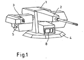
- FIG. 1 shows a weapon system 1 with main weapon 2 and secondary weapon 3, which can be mounted by means of a flange 4 on a vehicle (not shown).
- the main optics 8 is located on the flange 4 of the weapon system.
- a secondary optics 5 is grown below the secondary weapon 3.
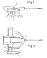
- Figures 2 and 3 show the arrangement from the side and from above.
- the secondary weapon 3 is outside the side of the main weapon 2 on a cultivation 6, which acts as a magazine for ammunition and also receives a beidenrichtantrieb 7 for the secondary weapon.
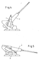
- Figures 4 and 5 show the main weapon 2 in an upper and a lower functional position of the height direction and associated with an upper and a lower operating position of the secondary weapon 3, wherein the secondary weapon 3 is directed further than the main weapon upwards or downwards.
- the secondary weapon 3 In the height direction, the secondary weapon 3 is initially directed with the main weapon 2 without the use of their own leveling drive 7 in height. When the main weapon 2 stops at a maximum elevation point above or below, the secondary weapon 3 can be directed further up or down than the main weapon by means of its own leveling drive 7.
- the main optics 8 can usually act only in the elevation range of the main weapon 2, the secondary weapon 3 is equipped with an additional rigidly coupled secondary optics 5.
- FIG. 6 illustrates a launcher 9 for camouflage and deception means, which is adapted to the height-orientable mass of the main armament 2 in the same way as the secondary armament.
- a launcher 9 for camouflage and deception means which is adapted to the height-orientable mass of the main armament 2 in the same way as the secondary armament.
- the secondary armament opens up by the combination of its own directional drive with the directional drive of the main weapon 2 also here large elevation options.
Landscapes
- Engineering & Computer Science (AREA)
- General Engineering & Computer Science (AREA)
- Aiming, Guidance, Guns With A Light Source, Armor, Camouflage, And Targets (AREA)
- Preparation Of Compounds By Using Micro-Organisms (AREA)
- Diaphragms For Electromechanical Transducers (AREA)
- Automobile Manufacture Line, Endless Track Vehicle, Trailer (AREA)
- Vehicle Body Suspensions (AREA)
Description
- Die Erfindung bezieht sich auf ein gepanzertes und bewaffnetes Fahrzeug, das sich aus den üblichen Teilen wie Antriebsmotor, Getrieben, Radsätzen oder Kettenlaufwerk, einem Besatzungsraum und einem Gehäuse, das alle Ein- und Anbauten aufnimmt, und einer Waffenanlage zusammensetzt.
- Bei der Bewaffnung wird ein großer Elevationsbereich für die Waffe immer wichtiger, um nahe und sehr hoch gelegene oder auch nahe und sehr tief liegende Ziele bekämpfen zu können. Dies kann zum Beispiel der Fall sein bei der Bekämpfung von Zielen in oberen Stockwerken von Gebäuden oder bei der Abwehr von Angreifern direkt neben dem Fahrzeug und betrifft vor allem die klein- oder mittelkalibrige Sekundärbewaffnung. Neben der Sekundärbewaffnung betrifft die Forderung nach großer Elevationsmöglichkeit zudem Wurfanlagen für Tarn- und Täuschmittel zur Top-Attack-Abwehr.
- Nach dem Stand der Technik sind verschiedene Vorschläge zur Erweiterung des Elevationsbereichs für Waffen an Fahrzeugen gemacht worden.
- Aus der DE 19927656A1 ist ein gepanzertes Transportkraftfahrzeug bekannt, welches mit einem unbemannten Schartenturm einschliesslich Lafette und Bordmaschinenwaffe als Bewaffnung ausgerüstet ist, der von der Besatzung aus dem Fahrzeuginneren fernbedient wird.
- Naturgemäß ist der Elevationsbereich von einer Hauptbewaffnung durch deren Waffenabmessungen und die Geometrie eines Trägerfahrzeugs begrenzt. Eine Sekundärbewaffnung, die achsparallel zur Hauptwaffe angebracht ist, kann dementsprechend nur den Elevationsbereich der Hauptwaffe erreichen, was in vielen Fällen nicht ausreicht. Deshalb wird der Forderung nach einem großen Elevationsbereich für die Sekundärwaffe konventionell mit zusätzlichen Lafetten unterschiedlichster Ausführung, wie zum Beispiel einer Freirichtlafette, einer bemannten oder unbemannten gesonderten Waffenstation, Rechnung getragen. Richtbare Wurfanlagen für Tarn- und Täuschmittel sind nach dem Stand der Technik ebenfalls als eigenständige Lafetten ausgeführt.
- Der Nachteil der vorhandenen Lösungen liegt vor allem darin, daß zusätzliche Lafetten Raumbedarf auf dem Fahrzeug- oder Turmdach haben, wobei Einbauplatz knapp ist und nur mit Einschränkungen und weiteren Nachteilen zur Verfügung gestellt werden kann und zusätzlicher Aufwand getrieben werden muß.
- Auch ist eine eigenständige Waffenstation aufgrund der zusätzlich benötigten Komponenten wie Richtanlage, Optik usw. aufwendig.
- Aufgabe der Erfindung ist es, eine Sekundärbewaffnung mit sehr großem Elevationsbereich und ohne eigenständige richtbare Lafette in Verbindung mit einer Hauptbewaffnung zur Verfügung zu stellen. Das Erfindungsprinzip sollte sich zudem auf Wurfanlagen für Tarn- und Täuschmittel anwenden lassen.
- Diese Aufgabe wird erfindungsgemäß durch die kennzeichnenden Merkmale des Anspruchs 1 gelöst. Weitere Merkmale ergeben sich aus den Unteransprüchen.
- Erfindungsgemäß wird eine höhenrichtbare Waffenaufnahme für eine Sekundärwaffe an die höhenrichtbare Masse der Hauptbewaffnung angeflanscht, so daß die Sekundärwaffe einen erweiterten Höhenrichtbereich erhält, der über den Höhenrichtbereich der Hauptwaffe hinausgeht.
- Dabei wird die Sekundärwaffe zum Beispiel seitlich von der Hauptwaffe, wo in der Regel Munitionsmagazine der Hauptwaffe angebaut sind, angebracht als Teil der höhenrichtbaren Teile der Hauptwaffe. Die Sekundärwaffe erhält einen eigenen und von der Hauptwaffe separaten Höhenrichtantrieb. Damit kann die Sekundärwaffe unabhängig von einer Höhenrichtung der Hauptwaffe in Höhe eingestellt werden in einem gewissen Bereich.
- Bei Einstellen der Höhenrichtung der Sekundärwaffe mittels der Höhenrichteinrichtung der Hauptwaffe und der Höheneinrichtung der Sekundärwaffe addieren sich die beiden Höhenrichtungen und die Sekundärwaffe kann weiter nach oben oder nach unten als die Hauptwaffe gerichtet werden.
- Die Vorteile der Erfindung liegen darin, dass sich die Elevationsbereiche von Haupt- und Sekundärbewaffnung addieren können je nach Funktionseinstellung und damit ein sehr großer Elevationsbereich für die Sekundärbewaffnung ermöglicht wird. Alternativ zu einer Sekundärbewaffnung lässt sich eine Wurfanlage für Tarn- und Täuschmittel in gleicher Weise an die höhenrichtbare Masse der Hauptbewaffnung adaptieren.
- Ausführungsbeispiele der Erfindung sind in den Zeichnungen schematisch dargestellt und werden im folgenden näher beschrieben. Es zeigen:
- Figur 1:
- eine Gesamtansicht der Waffenanlage mit einer Sekundärbewaffnung
- Figur 2:
- eine Seitenansicht der Waffenanlage
- Figur 3:
- eine Draufsicht der Waffenanlage
- Figur 4, 5:
- eine Seitenansicht der Waffenanlage mit Funktionsstellung
- Figur 6
- eine Gesamtansicht der Waffenanlage mit einer Wurfanlage
- Figur 1 zeigt eine Waffenanlage 1 mit Hauptwaffe 2 und Sekundärwaffe 3, die mittels eines Flansches 4 auf einem Fahrzeug (nicht dargestellt) angebaut werden kann. Die Hauptoptik 8 befindet sich am Flansch 4 der Waffenanlage. Eine Sekundäroptik 5 ist unterhalb der Sekundärwaffe 3 angebaut.
- Figur 2 und 3 zeigen die Anordnung von der Seite und von oben. Die Sekundärwaffe 3 ist außen seitlich an der Hauptwaffe 2 an einem Anbau 6, der als Magazin für Munition fungiert und ebenfalls einen Höhenrichtantrieb 7 für die Sekundärwaffe aufnimmt.
- Figur 4 und 5 zeigen die Hauptwaffe 2 in einer oberen und einer unteren Funktionsstellung der Höhenrichtung und zugeordnet dazu eine obere und eine untere Funktionsstellung der Sekundärwaffe 3, wobei die Sekundärwaffe 3 weiter als die Hauptwaffe nach oben respektive nach unten gerichtet wird.
- Bei der Höhenrichtung wird die Sekundärwaffe 3 zunächst mit der Hauptwaffe 2 ohne Einsatz des eigenen Richtantriebs 7 in der Höhe gerichtet. Bei Anschlag der Hauptwaffe 2 an einen maximalen Höhenrichtpunkt oben oder unten kann die Sekundärwaffe 3 mittels des eigenen Richtantriebs 7 weiter nach oben oder unten als die Hauptwaffe gerichtet werden.
- Da die Hauptoptik 8 in der Regel nur im Elevationsbereich der Hauptwaffe 2 agieren kann, ist die Sekundärwaffe 3 mit einer zusätzlichen starr gekoppelten Sekundäroptik 5 ausgestattet.
- Die Figur 6 verdeutlicht alternativ zur Sekundärbewaffnung 3 eine Wurfanlage 9 für Tarn- und Täuschmittel, die in gleicher Weise wie die Sekundärbewaffnung an die höhenrichtbare Masse der Hauptbewaffnung 2 adaptiert ist. In gleicher Weise wie bei der Sekundärbewaffnung eröffnen sich durch die Kombination des eigenen Richtantriebes mit dem Richtantrieb der Hauptwaffe 2 auch hier große Elevationsmöglichkeiten.
-
- 1
- Waffenanlage
- 2
- Hauptwaffe
- 3
- Sekundärwaffe
- 4
- Flansch
- 5
- Sekundäroptik
- 6
- Anbau
- 7
- Höhenrichtantrieb
- 8
- Hauptoptik
- 9
- Wurfanlage
Claims (10)
- Vorrichtung für die Höhenrichtung einer Sekundärbewaffnung an einem militärischen Fahrzeug mit einem Radfahr- oder Kettenlaufwerk und einem Antrieb zur Fortbewegung sowie einem Fahrzeugaufbau zur Aufnahme und Einbau aller Komponenten für den Betrieb des Fahrzeugs einschliesslich einer Fahrzeugbesatzung und einer Waffenanlage (1) mit einer Hauptbewaffnung (2) einschließlich einer Höhen- und Seitenrichteinrichtung
dadurch gekennzeichnet,
dass eine Sekundärbewaffnung (3) als Teil der höhenrichtbaren Masse der Hauptbewaffnung an die Hauptwaffe (2) angebaut ist einschließlich eines separaten Höhenrichtantriebes (7) für die Sekundärwaffe (3) und aller sonst benötigten Teile der Sekundärwaffe (3). - Vorrichtung nach Anspruch 1
dadurch gekennzeichnet,
dass die Sekundärwaffe (3) außen seitlich von der Hauptwaffe (2) als Teil oder Ersatz des dort angebauten Munitionsmagazins (6) der Hauptwaffe (2) angebaut ist. - Vorrichtung nach Anspruch 1,
dadurch gekennzeichnet,
dass die Sekundärwaffe (3) außen seitlich an die Hauptwaffe (2) als Teil des Waffenträgers der Hauptwaffe (2) angebaut ist. - Vorrichtung nach einem der Ansprüche 1 bis 3,
dadurch gekennzeichnet,
dass der Höhenrichtantrieb (7) für die Sekundärwaffe (3) die Schnittstelle und Lagerung der Sekundärwaffe (3) am Nlunitionsmagazin oder an der Hauptbewaffnung (2) bildet. - Vorrichtung nach einem der Ansprüche 1 bis 4,
dadurch gekennzeichnet,
dass die Sekundärwaffe (3) als leicht austauschbare Einheit anstelle eines der seitlichen Munitionsmagazine (6) der Hauptwaffe (2) angebaut ist. - Vorrichtung nach einem der Ansprüche 1 bis 5,
dadurch gekennzeichnet,
dass eine separat höhenrichtbare Waffenaufnahme als Adapter, Schnittstelle und Lagerung für eine anzubauende Sekundärwaffe (3) am Munitionsmagazin (6) der Hauptwaffe oder an der höhenrichtbaren Masse der Hauptbewaffnung angebaut ist. - Vorrichtung nach einem der Ansprüche 1 bis 6,
dadurch gekennzeichnet,
dass die Höhenrichteinrichtung (7) für die Sekundärwaffe (3) die Höhenrichtung unabhängig von der Hauptwaffeneinrichtung (2) vornehmen kann. - Vorrichtung nach einem der Ansprüche 1 bis 7,
dadurch gekennzeichnet,
dass die Sekundärwaffe (3) eine zugeordnete optronische Zieleinrichtung (5) besitzt, die starr mit der Sekundärwaffe (3) verbunden ist. - Vorrichtung nach einem der Ansprüche 1 bis 8,
dadurch gekennzeichnet,
dass der eigenständige Höhenrichtantrieb (7) der Sekundärwaffe (3) ein zum Beispiel elektrischer oder hydraulischer Fremdantrieb ist. - Vorrichtung nach einem der Ansprüche 1 bis 9,
dadurch gekennzeichnet,
dass nach dem gleichen Konstruktionsprinzip an Stelle einer Sekundärbewaffnung (3) eine Wurfanlage (9) für Tarn- und Täuschmittel eigenständig höhenrichtbar an die höhenrichtbare Masse der Hauptbewaffnung (2) angeflanscht ist.
Applications Claiming Priority (2)
| Application Number | Priority Date | Filing Date | Title |
|---|---|---|---|
| DE10160216A DE10160216C1 (de) | 2001-12-07 | 2001-12-07 | Eigenständig höhenrichtbare Sekundärbewaffnung |
| DE10160216 | 2001-12-07 |
Publications (3)
| Publication Number | Publication Date |
|---|---|
| EP1318374A2 EP1318374A2 (de) | 2003-06-11 |
| EP1318374A3 EP1318374A3 (de) | 2005-06-15 |
| EP1318374B1 true EP1318374B1 (de) | 2006-02-22 |
Family
ID=7708419
Family Applications (1)
| Application Number | Title | Priority Date | Filing Date |
|---|---|---|---|
| EP02021928A Expired - Lifetime EP1318374B1 (de) | 2001-12-07 | 2002-09-28 | Eigenständig höhenrichtbare Sekundärbewaffnung |
Country Status (5)
| Country | Link |
|---|---|
| EP (1) | EP1318374B1 (de) |
| AT (1) | ATE318401T1 (de) |
| DE (2) | DE10160216C1 (de) |
| ES (1) | ES2256383T3 (de) |
| NO (1) | NO324678B1 (de) |
Cited By (1)
| Publication number | Priority date | Publication date | Assignee | Title |
|---|---|---|---|---|
| DE102008037246B3 (de) * | 2008-08-09 | 2009-09-10 | Krauss-Maffei Wegmann Gmbh & Co. Kg | Waffenstation |
Families Citing this family (8)
| Publication number | Priority date | Publication date | Assignee | Title |
|---|---|---|---|---|
| DE10337642B4 (de) * | 2003-08-16 | 2007-08-02 | Kraus-Maffei Wegmann Gmbh & Co. Kg | Modulare Waffenstation, insbesondere zur Anordnung auf einem Kampffahrzeug |
| DE102004060779A1 (de) * | 2004-12-17 | 2006-06-29 | Krauss-Maffei Wegmann Gmbh & Co. Kg | Kampffahrzeug mit Flugabwehrsystem |
| DE102007041294B4 (de) | 2007-08-31 | 2009-12-17 | Rheinmetall Landsysteme Gmbh | Munitionsbevorratung |
| DE102007041292A1 (de) | 2007-08-31 | 2009-03-05 | Rheinmetall Landsysteme Gmbh | Modularer, adaptierbarer ballistischer Schutzaufbau insbesondere für einen Waffenturm |
| DE202009007415U1 (de) | 2009-05-25 | 2010-08-26 | Rheinmetall Waffe Munition Gmbh | Modularer Waffenträger |
| DE102010016560C5 (de) * | 2010-04-21 | 2014-06-05 | Krauss-Maffei Wegmann Gmbh & Co. Kg | Fahrzeug, insbesondere militärisches Kampffahrzeug |
| FR2991763B1 (fr) * | 2012-06-07 | 2014-06-20 | Panhard General Defense | Plateau tournant motorise pour elements additionnels de tourelle. |
| EP3306259A1 (de) | 2016-10-10 | 2018-04-11 | CMI Defence S.A. | Austauschbare standardstruktur für ein gepanzertes fahrzeug |
Family Cites Families (7)
| Publication number | Priority date | Publication date | Assignee | Title |
|---|---|---|---|---|
| US2444246A (en) * | 1942-11-20 | 1948-06-29 | Electric Boat Co | Gun turret |
| DE3119621A1 (de) * | 1981-05-16 | 1982-12-02 | Krauss-Maffei AG, 8000 München | Kampffahrzeug |
| DE3843258A1 (de) * | 1988-12-22 | 1990-07-05 | Rheinmetall Gmbh | Scheitellafettiertes geschuetz fuer ein panzerfahrzeug |
| DE3928614A1 (de) * | 1989-08-30 | 1992-10-08 | Wegmann & Co | Kampffahrzeug, insbesondere kampfpanzer |
| US5129307A (en) * | 1991-08-01 | 1992-07-14 | United States Of America As Represented By The Secretary Of The Navy | Side-mounted rolling airframe missile launcher |
| AT408690B (de) * | 1996-06-20 | 2002-02-25 | Dynamit Nobel Graz Gmbh | Steilfeuergeschütz, insbesondere granatwerfer |
| DE19927656A1 (de) * | 1999-06-17 | 2000-12-21 | Krauss Maffei Wegmann Gmbh & C | Gepanzertes Transportkraftfahrzeug |
-
2001
- 2001-12-07 DE DE10160216A patent/DE10160216C1/de not_active Expired - Fee Related
-
2002
- 2002-09-28 DE DE50205859T patent/DE50205859D1/de not_active Expired - Lifetime
- 2002-09-28 ES ES02021928T patent/ES2256383T3/es not_active Expired - Lifetime
- 2002-09-28 AT AT02021928T patent/ATE318401T1/de not_active IP Right Cessation
- 2002-09-28 EP EP02021928A patent/EP1318374B1/de not_active Expired - Lifetime
- 2002-10-14 NO NO20024929A patent/NO324678B1/no not_active IP Right Cessation
Cited By (3)
| Publication number | Priority date | Publication date | Assignee | Title |
|---|---|---|---|---|
| DE102008037246B3 (de) * | 2008-08-09 | 2009-09-10 | Krauss-Maffei Wegmann Gmbh & Co. Kg | Waffenstation |
| EP2151659A2 (de) | 2008-08-09 | 2010-02-10 | Krauss-Maffei Wegmann GmbH & Co. KG | Waffenstation |
| EP2151659A3 (de) * | 2008-08-09 | 2012-08-01 | Krauss-Maffei Wegmann GmbH & Co. KG | Waffenstation |
Also Published As
| Publication number | Publication date |
|---|---|
| EP1318374A3 (de) | 2005-06-15 |
| ES2256383T3 (es) | 2006-07-16 |
| EP1318374A2 (de) | 2003-06-11 |
| NO324678B1 (no) | 2007-12-03 |
| DE10160216C1 (de) | 2003-06-12 |
| NO20024929D0 (no) | 2002-10-14 |
| ATE318401T1 (de) | 2006-03-15 |
| DE50205859D1 (de) | 2006-04-27 |
| NO20024929L (no) | 2003-06-10 |
Similar Documents
| Publication | Publication Date | Title |
|---|---|---|
| EP1061323B2 (de) | Gepanzertes Transportkraftfahrzeug | |
| EP1495280B1 (de) | Kampffahrzeug mit rundblicksichtgerät, insbesondere schützen-und kampfpanzer | |
| DE102010016560C5 (de) | Fahrzeug, insbesondere militärisches Kampffahrzeug | |
| EP1318374B1 (de) | Eigenständig höhenrichtbare Sekundärbewaffnung | |
| DE102005020177A1 (de) | Wurfanlage | |
| EP2160563B1 (de) | Wurfanlage mit magazin | |
| DE102013100392A1 (de) | Vorrichtung und Verfahren zum Richten eines Raketenabschussbehälters | |
| DE10258263B4 (de) | Schießmodul | |
| DE102011050277A1 (de) | Adapter zur Befestigung einer Lafette an einem Objekt, Lafette und militärisches Fahrzeug | |
| EP1508765B1 (de) | Modulare Waffenstation, insbesondere zur Anordnung auf einem Kampffahrzeug | |
| EP1549899B1 (de) | Einrichtung zum schutz von objekten gegen als lenkflugkörper ausgebildete munitionen | |
| EP1563242B1 (de) | Integration eines grosskalibrigen geschützes auf einem schiff | |
| EP0844455B1 (de) | Anordnung eines Geschützes in einem Panzerturm | |
| DE2019144C1 (de) | Panzerfahrzeug mit niedriger Silhouette | |
| DE202005020752U1 (de) | Wurfanlage | |
| DE2820036A1 (de) | Anordnung einer startvorrichtung und visiereinrichtung fuer lenkflugkoerper | |
| EP1273869B1 (de) | Gepanzertes Fahrzeug | |
| DE1800330A1 (de) | Panzerfahrzeug mit Fliegerabwehrbewaffnung | |
| DE102021005473B3 (de) | Drohnengetragene Wirkmittel-Verschusseinrichtung | |
| DE102018113614A1 (de) | Flugabwehreffektor mit einem Turm und mit mindestens einem Such- und/oder Folgeradar | |
| DE102022103329A1 (de) | Waffenturm | |
| DE3303888A1 (de) | Anordung zur zielerfassung und identitizierung fuer gepanzerte kampffahrzeuge | |
| EP0651223B1 (de) | Militärisches Fahrzeug | |
| DE102018127967A1 (de) | Militärisches Panzerfahrzeug mit Teilfahrzeugen | |
| EP0392086A2 (de) | Flügelstabilisiertes Geschoss |
Legal Events
| Date | Code | Title | Description |
|---|---|---|---|
| PUAI | Public reference made under article 153(3) epc to a published international application that has entered the european phase |
Free format text: ORIGINAL CODE: 0009012 |
|
| AK | Designated contracting states |
Designated state(s): AT BE BG CH CY CZ DE DK EE ES FI FR GB GR IE IT LI LU MC NL PT SE SK TR |
|
| AX | Request for extension of the european patent |
Extension state: AL LT LV MK RO SI |
|
| PUAL | Search report despatched |
Free format text: ORIGINAL CODE: 0009013 |
|
| AK | Designated contracting states |
Kind code of ref document: A3 Designated state(s): AT BE BG CH CY CZ DE DK EE ES FI FR GB GR IE IT LI LU MC NL PT SE SK TR |
|
| AX | Request for extension of the european patent |
Extension state: AL LT LV MK RO SI |
|
| 17P | Request for examination filed |
Effective date: 20050512 |
|
| GRAP | Despatch of communication of intention to grant a patent |
Free format text: ORIGINAL CODE: EPIDOSNIGR1 |
|
| RAP1 | Party data changed (applicant data changed or rights of an application transferred) |
Owner name: RHEINMETALL LANDSYSTEME GMBH |
|
| GRAS | Grant fee paid |
Free format text: ORIGINAL CODE: EPIDOSNIGR3 |
|
| GRAA | (expected) grant |
Free format text: ORIGINAL CODE: 0009210 |
|
| AK | Designated contracting states |
Kind code of ref document: B1 Designated state(s): AT BE BG CH CY CZ DE DK EE ES FI FR GB GR IE IT LI LU MC NL PT SE SK TR |
|
| PG25 | Lapsed in a contracting state [announced via postgrant information from national office to epo] |
Ref country code: IE Free format text: LAPSE BECAUSE OF FAILURE TO SUBMIT A TRANSLATION OF THE DESCRIPTION OR TO PAY THE FEE WITHIN THE PRESCRIBED TIME-LIMIT Effective date: 20060222 Ref country code: FI Free format text: LAPSE BECAUSE OF FAILURE TO SUBMIT A TRANSLATION OF THE DESCRIPTION OR TO PAY THE FEE WITHIN THE PRESCRIBED TIME-LIMIT Effective date: 20060222 Ref country code: SK Free format text: LAPSE BECAUSE OF FAILURE TO SUBMIT A TRANSLATION OF THE DESCRIPTION OR TO PAY THE FEE WITHIN THE PRESCRIBED TIME-LIMIT Effective date: 20060222 Ref country code: NL Free format text: LAPSE BECAUSE OF FAILURE TO SUBMIT A TRANSLATION OF THE DESCRIPTION OR TO PAY THE FEE WITHIN THE PRESCRIBED TIME-LIMIT Effective date: 20060222 |
|
| REG | Reference to a national code |
Ref country code: GB Ref legal event code: FG4D Free format text: NOT ENGLISH |
|
| REG | Reference to a national code |
Ref country code: CH Ref legal event code: EP |
|
| AKX | Designation fees paid |
Designated state(s): AT BE BG CH CY CZ DE DK EE ES FI FR GB GR IE IT LI LU MC NL PT SE SK TR |
|
| GBT | Gb: translation of ep patent filed (gb section 77(6)(a)/1977) |
Effective date: 20060222 |
|
| REG | Reference to a national code |
Ref country code: IE Ref legal event code: FG4D Free format text: LANGUAGE OF EP DOCUMENT: GERMAN |
|
| REF | Corresponds to: |
Ref document number: 50205859 Country of ref document: DE Date of ref document: 20060427 Kind code of ref document: P |
|
| REG | Reference to a national code |
Ref country code: SE Ref legal event code: TRGR |
|
| PG25 | Lapsed in a contracting state [announced via postgrant information from national office to epo] |
Ref country code: DK Free format text: LAPSE BECAUSE OF FAILURE TO SUBMIT A TRANSLATION OF THE DESCRIPTION OR TO PAY THE FEE WITHIN THE PRESCRIBED TIME-LIMIT Effective date: 20060522 Ref country code: BG Free format text: LAPSE BECAUSE OF FAILURE TO SUBMIT A TRANSLATION OF THE DESCRIPTION OR TO PAY THE FEE WITHIN THE PRESCRIBED TIME-LIMIT Effective date: 20060522 |
|
| REG | Reference to a national code |
Ref country code: ES Ref legal event code: FG2A Ref document number: 2256383 Country of ref document: ES Kind code of ref document: T3 |
|
| PG25 | Lapsed in a contracting state [announced via postgrant information from national office to epo] |
Ref country code: PT Free format text: LAPSE BECAUSE OF FAILURE TO SUBMIT A TRANSLATION OF THE DESCRIPTION OR TO PAY THE FEE WITHIN THE PRESCRIBED TIME-LIMIT Effective date: 20060724 |
|
| NLV1 | Nl: lapsed or annulled due to failure to fulfill the requirements of art. 29p and 29m of the patents act | ||
| ET | Fr: translation filed | ||
| REG | Reference to a national code |
Ref country code: IE Ref legal event code: FD4D |
|
| PG25 | Lapsed in a contracting state [announced via postgrant information from national office to epo] |
Ref country code: CH Free format text: LAPSE BECAUSE OF NON-PAYMENT OF DUE FEES Effective date: 20060930 Ref country code: MC Free format text: LAPSE BECAUSE OF NON-PAYMENT OF DUE FEES Effective date: 20060930 Ref country code: BE Free format text: LAPSE BECAUSE OF NON-PAYMENT OF DUE FEES Effective date: 20060930 Ref country code: LI Free format text: LAPSE BECAUSE OF NON-PAYMENT OF DUE FEES Effective date: 20060930 |
|
| PLBE | No opposition filed within time limit |
Free format text: ORIGINAL CODE: 0009261 |
|
| STAA | Information on the status of an ep patent application or granted ep patent |
Free format text: STATUS: NO OPPOSITION FILED WITHIN TIME LIMIT |
|
| 26N | No opposition filed |
Effective date: 20061123 |
|
| REG | Reference to a national code |
Ref country code: CH Ref legal event code: PL |
|
| PG25 | Lapsed in a contracting state [announced via postgrant information from national office to epo] |
Ref country code: AT Free format text: LAPSE BECAUSE OF NON-PAYMENT OF DUE FEES Effective date: 20060928 |
|
| BERE | Be: lapsed |
Owner name: RHEINMETALL LANDSYSTEME G.M.B.H. Effective date: 20060930 |
|
| PG25 | Lapsed in a contracting state [announced via postgrant information from national office to epo] |
Ref country code: GR Free format text: LAPSE BECAUSE OF FAILURE TO SUBMIT A TRANSLATION OF THE DESCRIPTION OR TO PAY THE FEE WITHIN THE PRESCRIBED TIME-LIMIT Effective date: 20060523 Ref country code: CZ Free format text: LAPSE BECAUSE OF FAILURE TO SUBMIT A TRANSLATION OF THE DESCRIPTION OR TO PAY THE FEE WITHIN THE PRESCRIBED TIME-LIMIT Effective date: 20060222 |
|
| PG25 | Lapsed in a contracting state [announced via postgrant information from national office to epo] |
Ref country code: EE Free format text: LAPSE BECAUSE OF FAILURE TO SUBMIT A TRANSLATION OF THE DESCRIPTION OR TO PAY THE FEE WITHIN THE PRESCRIBED TIME-LIMIT Effective date: 20060222 |
|
| PG25 | Lapsed in a contracting state [announced via postgrant information from national office to epo] |
Ref country code: LU Free format text: LAPSE BECAUSE OF NON-PAYMENT OF DUE FEES Effective date: 20060928 Ref country code: TR Free format text: LAPSE BECAUSE OF FAILURE TO SUBMIT A TRANSLATION OF THE DESCRIPTION OR TO PAY THE FEE WITHIN THE PRESCRIBED TIME-LIMIT Effective date: 20060222 |
|
| PG25 | Lapsed in a contracting state [announced via postgrant information from national office to epo] |
Ref country code: CY Free format text: LAPSE BECAUSE OF FAILURE TO SUBMIT A TRANSLATION OF THE DESCRIPTION OR TO PAY THE FEE WITHIN THE PRESCRIBED TIME-LIMIT Effective date: 20060222 |
|
| REG | Reference to a national code |
Ref country code: FR Ref legal event code: PLFP Year of fee payment: 15 |
|
| PGFP | Annual fee paid to national office [announced via postgrant information from national office to epo] |
Ref country code: GB Payment date: 20160920 Year of fee payment: 15 Ref country code: DE Payment date: 20160921 Year of fee payment: 15 |
|
| PGFP | Annual fee paid to national office [announced via postgrant information from national office to epo] |
Ref country code: FR Payment date: 20160921 Year of fee payment: 15 Ref country code: SE Payment date: 20160920 Year of fee payment: 15 |
|
| PGFP | Annual fee paid to national office [announced via postgrant information from national office to epo] |
Ref country code: ES Payment date: 20160916 Year of fee payment: 15 |
|
| PGFP | Annual fee paid to national office [announced via postgrant information from national office to epo] |
Ref country code: IT Payment date: 20160922 Year of fee payment: 15 |
|
| REG | Reference to a national code |
Ref country code: DE Ref legal event code: R119 Ref document number: 50205859 Country of ref document: DE |
|
| REG | Reference to a national code |
Ref country code: SE Ref legal event code: EUG |
|
| GBPC | Gb: european patent ceased through non-payment of renewal fee |
Effective date: 20170928 |
|
| REG | Reference to a national code |
Ref country code: FR Ref legal event code: ST Effective date: 20180531 |
|
| PG25 | Lapsed in a contracting state [announced via postgrant information from national office to epo] |
Ref country code: GB Free format text: LAPSE BECAUSE OF NON-PAYMENT OF DUE FEES Effective date: 20170928 Ref country code: DE Free format text: LAPSE BECAUSE OF NON-PAYMENT OF DUE FEES Effective date: 20180404 |
|
| PG25 | Lapsed in a contracting state [announced via postgrant information from national office to epo] |
Ref country code: FR Free format text: LAPSE BECAUSE OF NON-PAYMENT OF DUE FEES Effective date: 20171002 Ref country code: IT Free format text: LAPSE BECAUSE OF NON-PAYMENT OF DUE FEES Effective date: 20170928 |
|
| REG | Reference to a national code |
Ref country code: ES Ref legal event code: FD2A Effective date: 20181017 |
|
| PG25 | Lapsed in a contracting state [announced via postgrant information from national office to epo] |
Ref country code: ES Free format text: LAPSE BECAUSE OF NON-PAYMENT OF DUE FEES Effective date: 20170929 |
|
| PG25 | Lapsed in a contracting state [announced via postgrant information from national office to epo] |
Ref country code: SE Free format text: LAPSE BECAUSE OF NON-PAYMENT OF DUE FEES Effective date: 20170929 |