EP1308352A2 - Procédé de montage d'un matériau protecteur et absorbant les chocs - Google Patents
Procédé de montage d'un matériau protecteur et absorbant les chocs Download PDFInfo
- Publication number
- EP1308352A2 EP1308352A2 EP20030075244 EP03075244A EP1308352A2 EP 1308352 A2 EP1308352 A2 EP 1308352A2 EP 20030075244 EP20030075244 EP 20030075244 EP 03075244 A EP03075244 A EP 03075244A EP 1308352 A2 EP1308352 A2 EP 1308352A2
- Authority
- EP
- European Patent Office
- Prior art keywords
- shock absorbing
- mounting
- adhesive
- head
- foam
- Prior art date
- Legal status (The legal status is an assumption and is not a legal conclusion. Google has not performed a legal analysis and makes no representation as to the accuracy of the status listed.)
- Granted
Links
Images


Classifications
-
- F—MECHANICAL ENGINEERING; LIGHTING; HEATING; WEAPONS; BLASTING
- F16—ENGINEERING ELEMENTS AND UNITS; GENERAL MEASURES FOR PRODUCING AND MAINTAINING EFFECTIVE FUNCTIONING OF MACHINES OR INSTALLATIONS; THERMAL INSULATION IN GENERAL
- F16F—SPRINGS; SHOCK-ABSORBERS; MEANS FOR DAMPING VIBRATION
- F16F7/00—Vibration-dampers; Shock-absorbers
- F16F7/12—Vibration-dampers; Shock-absorbers using plastic deformation of members
- F16F7/121—Vibration-dampers; Shock-absorbers using plastic deformation of members the members having a cellular, e.g. honeycomb, structure
-
- B—PERFORMING OPERATIONS; TRANSPORTING
- B60—VEHICLES IN GENERAL
- B60R—VEHICLES, VEHICLE FITTINGS, OR VEHICLE PARTS, NOT OTHERWISE PROVIDED FOR
- B60R21/00—Arrangements or fittings on vehicles for protecting or preventing injuries to occupants or pedestrians in case of accidents or other traffic risks
- B60R21/02—Occupant safety arrangements or fittings, e.g. crash pads
- B60R21/04—Padded linings for the vehicle interior ; Energy absorbing structures associated with padded or non-padded linings
-
- C—CHEMISTRY; METALLURGY
- C09—DYES; PAINTS; POLISHES; NATURAL RESINS; ADHESIVES; COMPOSITIONS NOT OTHERWISE PROVIDED FOR; APPLICATIONS OF MATERIALS NOT OTHERWISE PROVIDED FOR
- C09J—ADHESIVES; NON-MECHANICAL ASPECTS OF ADHESIVE PROCESSES IN GENERAL; ADHESIVE PROCESSES NOT PROVIDED FOR ELSEWHERE; USE OF MATERIALS AS ADHESIVES
- C09J7/00—Adhesives in the form of films or foils
- C09J7/20—Adhesives in the form of films or foils characterised by their carriers
- C09J7/22—Plastics; Metallised plastics
- C09J7/26—Porous or cellular plastics
-
- F—MECHANICAL ENGINEERING; LIGHTING; HEATING; WEAPONS; BLASTING
- F16—ENGINEERING ELEMENTS AND UNITS; GENERAL MEASURES FOR PRODUCING AND MAINTAINING EFFECTIVE FUNCTIONING OF MACHINES OR INSTALLATIONS; THERMAL INSULATION IN GENERAL
- F16F—SPRINGS; SHOCK-ABSORBERS; MEANS FOR DAMPING VIBRATION
- F16F7/00—Vibration-dampers; Shock-absorbers
- F16F7/12—Vibration-dampers; Shock-absorbers using plastic deformation of members
-
- B—PERFORMING OPERATIONS; TRANSPORTING
- B60—VEHICLES IN GENERAL
- B60R—VEHICLES, VEHICLE FITTINGS, OR VEHICLE PARTS, NOT OTHERWISE PROVIDED FOR
- B60R21/00—Arrangements or fittings on vehicles for protecting or preventing injuries to occupants or pedestrians in case of accidents or other traffic risks
- B60R21/02—Occupant safety arrangements or fittings, e.g. crash pads
- B60R21/04—Padded linings for the vehicle interior ; Energy absorbing structures associated with padded or non-padded linings
- B60R2021/0414—Padded linings for the vehicle interior ; Energy absorbing structures associated with padded or non-padded linings using energy absorbing ribs
-
- B—PERFORMING OPERATIONS; TRANSPORTING
- B60—VEHICLES IN GENERAL
- B60R—VEHICLES, VEHICLE FITTINGS, OR VEHICLE PARTS, NOT OTHERWISE PROVIDED FOR
- B60R21/00—Arrangements or fittings on vehicles for protecting or preventing injuries to occupants or pedestrians in case of accidents or other traffic risks
- B60R21/02—Occupant safety arrangements or fittings, e.g. crash pads
- B60R21/04—Padded linings for the vehicle interior ; Energy absorbing structures associated with padded or non-padded linings
- B60R2021/0442—Padded linings for the vehicle interior ; Energy absorbing structures associated with padded or non-padded linings associated with the roof panel
-
- C—CHEMISTRY; METALLURGY
- C09—DYES; PAINTS; POLISHES; NATURAL RESINS; ADHESIVES; COMPOSITIONS NOT OTHERWISE PROVIDED FOR; APPLICATIONS OF MATERIALS NOT OTHERWISE PROVIDED FOR
- C09J—ADHESIVES; NON-MECHANICAL ASPECTS OF ADHESIVE PROCESSES IN GENERAL; ADHESIVE PROCESSES NOT PROVIDED FOR ELSEWHERE; USE OF MATERIALS AS ADHESIVES
- C09J2421/00—Presence of unspecified rubber
- C09J2421/006—Presence of unspecified rubber in the substrate
-
- C—CHEMISTRY; METALLURGY
- C09—DYES; PAINTS; POLISHES; NATURAL RESINS; ADHESIVES; COMPOSITIONS NOT OTHERWISE PROVIDED FOR; APPLICATIONS OF MATERIALS NOT OTHERWISE PROVIDED FOR
- C09J—ADHESIVES; NON-MECHANICAL ASPECTS OF ADHESIVE PROCESSES IN GENERAL; ADHESIVE PROCESSES NOT PROVIDED FOR ELSEWHERE; USE OF MATERIALS AS ADHESIVES
- C09J2423/00—Presence of polyolefin
- C09J2423/006—Presence of polyolefin in the substrate
-
- C—CHEMISTRY; METALLURGY
- C09—DYES; PAINTS; POLISHES; NATURAL RESINS; ADHESIVES; COMPOSITIONS NOT OTHERWISE PROVIDED FOR; APPLICATIONS OF MATERIALS NOT OTHERWISE PROVIDED FOR
- C09J—ADHESIVES; NON-MECHANICAL ASPECTS OF ADHESIVE PROCESSES IN GENERAL; ADHESIVE PROCESSES NOT PROVIDED FOR ELSEWHERE; USE OF MATERIALS AS ADHESIVES
- C09J2433/00—Presence of (meth)acrylic polymer
-
- C—CHEMISTRY; METALLURGY
- C09—DYES; PAINTS; POLISHES; NATURAL RESINS; ADHESIVES; COMPOSITIONS NOT OTHERWISE PROVIDED FOR; APPLICATIONS OF MATERIALS NOT OTHERWISE PROVIDED FOR
- C09J—ADHESIVES; NON-MECHANICAL ASPECTS OF ADHESIVE PROCESSES IN GENERAL; ADHESIVE PROCESSES NOT PROVIDED FOR ELSEWHERE; USE OF MATERIALS AS ADHESIVES
- C09J2475/00—Presence of polyurethane
- C09J2475/006—Presence of polyurethane in the substrate
-
- Y—GENERAL TAGGING OF NEW TECHNOLOGICAL DEVELOPMENTS; GENERAL TAGGING OF CROSS-SECTIONAL TECHNOLOGIES SPANNING OVER SEVERAL SECTIONS OF THE IPC; TECHNICAL SUBJECTS COVERED BY FORMER USPC CROSS-REFERENCE ART COLLECTIONS [XRACs] AND DIGESTS
- Y10—TECHNICAL SUBJECTS COVERED BY FORMER USPC
- Y10T—TECHNICAL SUBJECTS COVERED BY FORMER US CLASSIFICATION
- Y10T156/00—Adhesive bonding and miscellaneous chemical manufacture
- Y10T156/10—Methods of surface bonding and/or assembly therefor
- Y10T156/1089—Methods of surface bonding and/or assembly therefor of discrete laminae to single face of additional lamina
-
- Y—GENERAL TAGGING OF NEW TECHNOLOGICAL DEVELOPMENTS; GENERAL TAGGING OF CROSS-SECTIONAL TECHNOLOGIES SPANNING OVER SEVERAL SECTIONS OF THE IPC; TECHNICAL SUBJECTS COVERED BY FORMER USPC CROSS-REFERENCE ART COLLECTIONS [XRACs] AND DIGESTS
- Y10—TECHNICAL SUBJECTS COVERED BY FORMER USPC
- Y10T—TECHNICAL SUBJECTS COVERED BY FORMER US CLASSIFICATION
- Y10T428/00—Stock material or miscellaneous articles
- Y10T428/24—Structurally defined web or sheet [e.g., overall dimension, etc.]
- Y10T428/24479—Structurally defined web or sheet [e.g., overall dimension, etc.] including variation in thickness
- Y10T428/24496—Foamed or cellular component
- Y10T428/24504—Component comprises a polymer [e.g., rubber, etc.]
- Y10T428/24512—Polyurethane
-
- Y—GENERAL TAGGING OF NEW TECHNOLOGICAL DEVELOPMENTS; GENERAL TAGGING OF CROSS-SECTIONAL TECHNOLOGIES SPANNING OVER SEVERAL SECTIONS OF THE IPC; TECHNICAL SUBJECTS COVERED BY FORMER USPC CROSS-REFERENCE ART COLLECTIONS [XRACs] AND DIGESTS
- Y10—TECHNICAL SUBJECTS COVERED BY FORMER USPC
- Y10T—TECHNICAL SUBJECTS COVERED BY FORMER US CLASSIFICATION
- Y10T428/00—Stock material or miscellaneous articles
- Y10T428/24—Structurally defined web or sheet [e.g., overall dimension, etc.]
- Y10T428/24628—Nonplanar uniform thickness material
- Y10T428/24669—Aligned or parallel nonplanarities
- Y10T428/24678—Waffle-form
-
- Y—GENERAL TAGGING OF NEW TECHNOLOGICAL DEVELOPMENTS; GENERAL TAGGING OF CROSS-SECTIONAL TECHNOLOGIES SPANNING OVER SEVERAL SECTIONS OF THE IPC; TECHNICAL SUBJECTS COVERED BY FORMER USPC CROSS-REFERENCE ART COLLECTIONS [XRACs] AND DIGESTS
- Y10—TECHNICAL SUBJECTS COVERED BY FORMER USPC
- Y10T—TECHNICAL SUBJECTS COVERED BY FORMER US CLASSIFICATION
- Y10T428/00—Stock material or miscellaneous articles
- Y10T428/249921—Web or sheet containing structurally defined element or component
- Y10T428/249953—Composite having voids in a component [e.g., porous, cellular, etc.]
-
- Y—GENERAL TAGGING OF NEW TECHNOLOGICAL DEVELOPMENTS; GENERAL TAGGING OF CROSS-SECTIONAL TECHNOLOGIES SPANNING OVER SEVERAL SECTIONS OF THE IPC; TECHNICAL SUBJECTS COVERED BY FORMER USPC CROSS-REFERENCE ART COLLECTIONS [XRACs] AND DIGESTS
- Y10—TECHNICAL SUBJECTS COVERED BY FORMER USPC
- Y10T—TECHNICAL SUBJECTS COVERED BY FORMER US CLASSIFICATION
- Y10T428/00—Stock material or miscellaneous articles
- Y10T428/28—Web or sheet containing structurally defined element or component and having an adhesive outermost layer
Definitions
- the present invention relates to a shock absorbing material, and in particular relates to a shock absorbing material for automobiles, suitable for reducing head injury criteria by absorbing shock energy imparted to the heads of passengers in the car interior at the time of a crash.
- the present invention also relates to a method for easily and securely mounting a protecting material to the car body, the ceiling material, the trim, or the like for improving safety by absorbing and reducing shock energy imparted to the heads or other body parts of passengers in the car interior at the time of a crash.
- Japanese Unexamined Utility Model Publication No. 6-42437 uses a rigid polyurethane foam as the protecting material for shocks to the head; however, since it has a composite structure with a hollow-shaped resin part (trim), the compression stress of the rigid polyurethane foam must be as low as 0.2 to 2 kg/cm 2 , and thus the optimum structure utilizing the characteristics of the polyurethane foam cannot be provided. Moreover, since the irregular shape is for reducing the weight and maintaining strength thereof, but is not for improving the shock absorbing ability, the shock absorbing ability cannot be improved.
- Japanese Unexamined Patent Publication No. 8-2358 describes an example of the conventional technique of a pad shock absorbing material comprising a foam material or a rubber material.
- the pad is elastically deformed, and thus it is not a rigid polyurethane foam.
- the concave shape since the part contacting the car body is extremely thin, the pad must be thick in order to yield sufficient shock absorbing ability, and thus problems arise in that due to reduced car interior space in the automobile, comfort, convenience in entering and exiting, and visibility range are degraded.
- Japanese Unexamined Patent Publication No. 8-72642 has an overall concave shock absorbing structure.
- the soft or rigid polyurethane foam itself used as the cushion material does not have an irregular shape to improve performance, but has a concave shape only at the mounting part.
- a sufficient shock absorbing ability cannot be achieved with an overall excessively high or low rigidity, but a specific numerical value or range is not described, and thus it is difficult to ensure that good shock absorbing ability can be obtained.
- a force is applied to a face contact part locally, particularly by a spherical object such as the head of a dummy, the force is concentrated in the beam part between ribs, as disclosed in Japanese Unexamined Patent Publication No. 7-16867, comprising a bead-like molded resin, and thus sufficient shock absorbing ability cannot be obtained.
- the shaped part is made of a rigid polyurethane foam, the beam part will break. As a result, a distance effective for absorbing energy cannot be obtained.
- the head protecting material in general, is a strip-like member about 60 mm ⁇ 450 mm x 20 mm.
- those comprising a rigid polyurethane foam those comprising a bead-like foamed member of a polypropylene, polyethylene or polyolefin resin, resin ribs of an ABS, polypropylene, polyethylene, polyolefin, or the like, have been provided.
- These head protecting materials are made of a material with a relatively high hardness.
- a head protecting material In mounting such a head protecting material to, for example, the rear surface of a ceiling material of an automobile, it is mounted along the sides of the ceiling material 10 corresponding to the seat position of passengers as shown in FIG. 13A as 11A, 11B, 11C, 11D. As shown in FIG. 13B (enlarged view of the cross-section taken on the line XIIIB-XIIIB of FIG. 13A), an adhesive tape 12 or an adhesive is used for mounting.
- the adhesive tape 12 one comprising a base material of non-woven fabric, paper, plastic film, or the like, and an adhesive material applied thereon for forming an adhesive layer has been used.
- the adhesive a hot melt adhesive, a solvent adhesive, or an aqueous adhesive has been used.
- the conventional head protecting material mounting method involves the following problems.
- the mounting operation itself can be easier by mounting with an adhesive tape compared with the case of using an adhesive
- the head protecting material is made of a relatively hard material and thus cannot follow the deformation of the mounted surface, the head protecting material can easily peel and fall off. That is, if the head protecting material is mounted to a part of a flat and wide area like the rear surface of the ceiling material, when the part is deformed by twisting during transportation, the adhesive surface peels and falls off due to inability to conform to the deformations of the hard the head protecting material.
- the head protecting material projects from the part, such as the ceiling material for the thickness thereof as a level difference, the projecting head protecting material contacts the car body, or the like, the head protecting material falls off from the part also in this case due to inability of the adhesive surface to follow the deformation for the hardness of the head protecting material.
- the head protecting material needs to be fixed and held for 20 to 30 seconds after application when a hot melt adhesive is used, and an standing time is required after application of an adhesive in the case of a solvent adhesive, both require a large number of bonding steps, and thus are difficult to execute.
- both the hot melt adhesive and the solvent adhesive become adhesive by hardening and the adhered to surface becomes hard, the adhered to surface cannot conform to the deformation when there is deformation during transportation or a crash of the car body so that a problem arises in which the head protecting material falls off, as in the case of the adhesive tape.
- a first aim of the present invention is to provide a shock absorbing material for an automobile having extremely good shock absorbing ability and which is suitable for absorbing shock energy from a pillar impacting a head of a passenger including a driver in a cabin at the time of a crash of an automobile, or the like, and reducing head injury criteria.
- a shock absorbing material according to the present invention consists of a rigid polyurethane foam having a 3 kg/cm 2 or more compression stress, and has a shape of a board with concave parts arranged on at least one planar surface thereof.
- shock absorbing material in the shock absorbing material according to the present invention, stable shock absorbing ability can be achieved by absorbing shock energy by crushing of at least one wall part between the adjacent concave portions in the shock absorbing material, and by the crushed wall(s) entering into the concave portions successively. Furthermore, owing to the entrance of the crushed wall into the concave portions, a large stroke can be obtained, and thus the shock value to be applied to the passengers can be reduced sufficiently.
- the ratio of the volume of the concave portions with respect to the total of the volume of the rigid polyurethane foam part and the volume of the concave portions (hereinafter the ratio may be referred to as the "excavated ratio”) be 10 to 40%.
- the concave portions are arranged parallel in one direction, with an arrangement pitch of 30 mm or less, and that the width of the wall between the adjacent concave portions has a thickness of 2 to 15 mm.
- the shock absorbing material of the present invention may be mounted to an automobile body or an interior part such as a head liner, a trim, or the like thereof as a protecting material against shocks to a head of a person in a cabin of the automobile.
- a second aim of the present invention is to provide a method for mounting a protecting material to a ceiling material, a trim, an automobile body, or the like easily and securely.
- the adhesive sheet comprises a base material made of a foam material and an adhesive layer formed thereon.
- the adhesive sheet having a foam material as the base material With the adhesive sheet having a foam material as the base material, peeling off or falling off of the protecting material can be prevented due to deformation of the foam material provided as the base material.
- the density of the foam material comprising the base material of the adhesive sheet is 0.005 to 0.5 g/cm 3 , and the base material thickness is 0.5 to 5 mm.
- FIGS. 1 and 2 are cross-sectional views showing embodiments of a shock absorbing material according to the present invention
- FIG. 3 is a cross-sectional view taken along the line III-III in FIGS. 1 and 2.
- a shock absorbing material 1 shown in FIG. 1 comprises a planar member 2 made of a rigid polyurethane foam, with one planar surface provided with concave portions 3 with a rectangular planar shape, arranged parallel in the longitudinal direction of the planar member 2.
- the material 1 absorbs shock energy applied thereto by crushing of at least one wall part 4 between the adjacent concave parts 3 and 3, and by the crushed wall entering into the concave portion 3, so that good shock absorbing ability can be obtained.
- a shock absorbing material 1A shown in FIG. 2 is provided with concave portions 3A with a substantially square planar shape arranged parallel in two rows in the longitudinal direction of a planar member 2A. Also shock absorbing material 1A, owing to crushing of a wall part 4A between the adjacent concave portions 3A and 3A by shock and entrance of the destroyed portion into the concave portions 3A, good shock absorbing ability can be obtained.
- the material for absorbing shock is made of a rigid polyurethane foam having a compression stress of 3 kg/cm 2 or more. If the rigid polyurethane foam has a compression stress less than 3 kg/cm 2 (29.4 N/cm 2 ), the strength of the wall part between the adjacent concave portions is insufficient so that sufficient shock absorbing ability cannot be obtained by the crush of the wall part in the initial stage of application of a shock.
- the compression of the rigid polyurethane foam is preferally from about 3 to 40 kg/cm 2 (29.4 N/cm 2 to 392 N/cm 2 ).
- the excavated ratio is defined to be 10 to 40%, and is preferably 15 to 35%.
- the shock absorbing ability may differ according to the portion of the planar surface of the shock absorbing material with the concave portions formed thereon with a pitch arrangement of more than 30 mm of the concave parts (distance between the central axes of the adjacent concave portions in plane view), it is preferable that the arrangement pitch of the concave portions is 30 mm or less.
- the arrangement pitch is preferably 10 mm or more.
- the thickness of the wall part is preferably 2 to 15 mm, and is more preferably 5 to 10 mm.
- the depth of the concave portions can be determined optionally according to the arrangement pitch, the thickness of the wall part, or the like within the range capable of obtaining the above-mentioned excavation ratio, but in general, it is preferable that the depth of the concave portions is about 1/3 to 3/4 of the total thickness of the shock absorbing material.
- the shape of the concave portions is not particularly limited.
- the planar shape can be, in addition to a rectangular shape as shown in FIG. 1 and a square shape as shown in FIG. 2, the concave portions 3A can be a parallelogram as shown in FIG. 4A, or an irregular quadrilateral, such as a trapezoid, or the like.
- any other shape such as a triangle, a circle, an ellipse, a gourd shape, and the like may be used. As shown in FIG.
- concave portion 3B an optional combination of concave portion with different shapes including a triangular concave portion 3B, a circular concave portion 3C, an elliptical concave portion 3D, and a gourd-shaped concave portion 3E can be used as well. Furthermore, as shown in FIG. 4C, one end of the concave portion 3F can reach one side surface 2A of the planar member 2.
- the shock absorbing material 1B can have the concave portions 3B with an inverted trapezoidal cross-section (funnel-shaped) as shown in FIG. 5. Furthermore, the shock absorbing material 1C can have curved edge portions at the upper end part and the bottom portion of the concave portions 3C of the wall parts 4C as shown in FIG. 6.
- the concave portions can be disposed in two or more rows, and the arrangement is not limited to a linear one, but can be zigzag, or the like.
- the shock absorbing materials 1B and 1C With the shock absorbing materials 1B and 1C, adjustment, formability, direction stability, or the like, of the shock absorbing ability can be improved. Moreover, the concave portions can be formed not only in one surface but in both surfaces of the planar member.
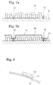
- the shock absorbing material 10 of the present invention can be fixed mechanically with a vise, or the like, to a steel plate 11, or the like, of the car body as shown in FIG. 7A.
- the shock absorbing material 10 of the present invention can be attached to an interior part 13 of the car body (for example, a sheet of a ceiling part, or the like) with an adhesive 14 or an adhesive tape.
- the surface in mounting to a side rail, or the like, in order to stabilize the impact characteristics, or the like, the surface can be pressed with a surface material 15 of a steel plate, a resin plate, or the like, as shown in FIG. 7B.
- the surface material 15 can be mounted by adhering or bonding with the shock absorbing material 10. By attaching the surface material 15 accordingly, the shock absorbing material 10 can be mounted easily to the car body and the mounting strength can be improved.
- the concave portion of the shock absorbing material can be disposed either at the inner side or the outer side of the interior of a car.
- the arrangement direction can be determined optionally according to mounting stability, shock absorbing ability stability, or the like.
- shock absorbing material according to the present invention will be explained more specifically with reference to examples and comparative examples.
- the shock absorbing ability as a head protecting material was measured by the shock applied on a dummy in an acceleration in a dynamic evaluation test using the dummy, and the extent of the head injury criteria (HIC (d)) calculated from the acceleration were evaluated.
- HIC (d) head injury criteria
- an HIC (d) of 1,000 or less is evaluated to be excellent in terms of shock absorbing ability.
- a shock absorbing material with the shape shown in FIGS. 1 and 3 was produced from a rigid polyurethane foam having a compression stress of 15 kg/cm 2 .
- the shock absorbing material comprises a planar member having an external size of 210 mm (in the longitudinal direction) x 60 mm (in the lateral direction) ⁇ 20 mm (in the vertical direction), with concave portions of 50 mm x 10 mm x 10 mm (depth) provided parallel with an arrangement pitch of 15 mm with a 5 mm thickness T of the wall parts, and a 28% excavation ratio.
- the head injury criteria were measured for a shock absorbing material 20 with groove parts 21 arranged parallel as shown in FIG. 9. Results are shown in Table 1.
- the material comprising the shock absorbing material 20 is the same rigid polyurethane foam used in Example 1.
- the external size thereof is the same as that of Example 1.
- the excavation ratio (the volume ratio of the groove parts with respect to the volume of the groove parts and the rigid polyurethane foam part) is 33%.
- the head injury criteria were measured for a shock absorbing material 30 with a groove part 31 formed in the longitudinal direction as shown in FIG. 10. Results are shown in Table 1.
- the material comprising the shock absorbing material 30 is the same rigid polyurethane foam used in Example 1.
- the external size thereof is the same as that of Example 1.
- the excavation ratio (the volume ratio of the groove parts with respect to the volume of the groove parts and the rigid polyurethane foam part) is 33%.
- Example 1 A shock absorbing material was produced in the same manner as in Example 1, except that a rigid polyurethane foam having a compression stress of 2.8 kg/cm 2 was used, and the head injury criteria were measured. Results are shown in Table 1.
- Example Compression stress of the rigid polyurethane foam (kg/cm 2 ) Excavation ratio (%) Head injury criteria HIC(d)
- Example 1 15 28 770 Comparative Example 1 33 1100 Comparative Example 2 33 1300 Comparative Example 3 2.8 28 2100
- a shock absorbing material was produced in the same manner as Example 1 except that the concave portions were formed so as to have the width of the wall part and the excavation ratio of the values shown in Table 2, and the head injury criteria were measured. Results are shown in Table 2. No. Draft ratio Width of the wall part (mm) Head injury criteria HIC(d) 1 6 15 1200 2 11 10 1100 3 19 15 1000 4 28 5 770 5 31 5 940 6 43 5 1250 7 52 5 1900
- a shock absorbing material was produced in the same manner as in Example 1 except that the arrangement pitch of the concave portions was 35 mm, with the concave portion size changed so as to have the same excavation ratio.
- the head injury criteria can be 1,000 or less depending on the impact position, but the value fluctuates depending on the impact position, and thus it is disadvantageous due to slight inferiority of performance stability and reliability.
- shock absorbing material of the present invention a shock absorbing material for automobiles, having extremely good shock absorbing ability, capable of absorbing shock energy applied to the heads of passengers in a car interior at the time of a crash, or the like, and reducing the head injury criteria can be provided.
- FIG. 11 is a cross-sectional view showing an embodiment of a method for mounting a protecting material according to the present invention.
- FIGS. 12A to 12D are plan views showing embodiments of attaching an adhesive tape.
- an adhesive sheet (in FIG. 1, adhesive tape) 3 comprising a base material 3A made of a foam material with an adhesive layer 3B formed thereon is used for mounting a head protecting material 1 onto a ceiling material 2, or the like.
- the present invention can be adopted for mounting the head protecting material not only to the ceiling material but also to any of the other interior materials and to the car body.
- the foam material comprising the base material of the adhesive sheet to be used in the present invention
- various foam materials such as polyolefin resin foams including soft polyurethane foam, polypropylene, polyethylene, or the like, a foam rubber, or the like may be mentioned.
- the density thereof it is desirably in the range of 0.005 to 0.5 g/cm 3 , in particular, 0.005 to 0.2 g/cm 3 . That is, since a foam material with a high density of more than 0.5 g/cm 3 cannot conform to deformation due to the hardness thereof, the falling off preventing effect of the head protecting material cannot be sufficiently obtained.
- a low density foam material with a density less than 0.005 g/cm 3 can be easily ruptured or damaged by handling since the strength of the foam material is low, and thus it is not practical.
- the thickness of the base material comprising the foam material is preferably in the range of 0.5 to 5 mm. That is, a thin base material with a thickness of less than 0.5 mm cannot sufficiently yield the effects of preventing the falling off caused by the base material deformation of the head protecting material. Furthermore, since the clearance of the parts is set to about 5 mm or less in an ordinary car body, with a base substrate having a thickness of more than 5 mm, the adhesive sheet portion is thicker than the clearance so that the head protecting material can fall off by contact with the car body during assembling with the car body, or the head protecting material contacts with other parts, generating strange noises, and thus it is not preferable.
- the base material of the adhesive sheet when a shock is applied to the head protecting material mounted with the adhesive sheet, the base material of the adhesive sheet can be substantially deformed depending on the direction of the shock so as to generate displacement of the head protecting material, and thus the initial load necessary for protecting the head from shock cannot be obtained, and the head protecting material cannot perform the function thereof.
- shocks since shocks may be applied from various directions to the head protecting material, it is extremely important to ensure prevention of such displacement in order to protect the head.
- the adhesive material of the adhesive layer to be formed on the base material an ordinary adhesive material, such as acrylic, rubber, of the like, can be used.
- the adhesive layer is formed with such an adhesive material at a thickness of about 0.01 to 1 mm.
- the method for attaching the adhesive sheet is not particularly limited, but a band-like adhesive tape 3 can be attached in the longitudinal direction of the head protecting material 1 as shown in FIG. 12A, or an adhesive tape 3 cut in a short length can be attached at a plurality of points on the head protecting material 1, as shown in FIGS. 12B and 12C. Moreover, as shown in FIG. 12D, an adhesive tape 3 can be attached according to the shape of the head protecting material 1 with an irregular shape.
- a band-like adhesive tape can be used accordingly as the adhesive sheet, or a small sticker-like adhesive sheet of a quadrilateral shape, circular shape, or the like, can be used. It can be selected and used optionally according to the shape, size, the shape of the part to be mounted, or the like, of the head protecting material.
- Example 3 in mounting a protecting material such as a head protecting material using an adhesive tape, capable of being easily and inexpensively mounted, with superior mounting operability, without the need for fixing time or holding time, deformation of the part mounted with the protecting material during handling, or peeling off or falling off of the protecting material at the time of impact by another part can be prevented. Therefore, according to the present invention, a protecting material can be mounted easily, securely, and firmly to a part, which can be drastically deformed or have shock applied thereto, such as a ceiling material, a trim, a car body, or the like, of an automobile.
- a protecting material such as a head protecting material using an adhesive tape
Applications Claiming Priority (5)
| Application Number | Priority Date | Filing Date | Title |
|---|---|---|---|
| JP10177451A JP2000006741A (ja) | 1998-06-24 | 1998-06-24 | 衝撃吸収材 |
| JP17745198 | 1998-06-24 | ||
| JP25394798 | 1998-09-08 | ||
| JP10253947A JP2000085487A (ja) | 1998-09-08 | 1998-09-08 | 保護材の取り付け方法 |
| EP19990304926 EP0967124B1 (fr) | 1998-06-24 | 1999-06-23 | Matériau absorbeur de chocs |
Related Parent Applications (1)
| Application Number | Title | Priority Date | Filing Date |
|---|---|---|---|
| EP19990304926 Division EP0967124B1 (fr) | 1998-06-24 | 1999-06-23 | Matériau absorbeur de chocs |
Publications (3)
| Publication Number | Publication Date |
|---|---|
| EP1308352A2 true EP1308352A2 (fr) | 2003-05-07 |
| EP1308352A3 EP1308352A3 (fr) | 2003-07-09 |
| EP1308352B1 EP1308352B1 (fr) | 2005-07-27 |
Family
ID=26497988
Family Applications (2)
| Application Number | Title | Priority Date | Filing Date |
|---|---|---|---|
| EP19990304926 Expired - Lifetime EP0967124B1 (fr) | 1998-06-24 | 1999-06-23 | Matériau absorbeur de chocs |
| EP20030075244 Expired - Lifetime EP1308352B1 (fr) | 1998-06-24 | 1999-06-23 | Procédé de montage d'un matériau protecteur et absorbant les chocs |
Family Applications Before (1)
| Application Number | Title | Priority Date | Filing Date |
|---|---|---|---|
| EP19990304926 Expired - Lifetime EP0967124B1 (fr) | 1998-06-24 | 1999-06-23 | Matériau absorbeur de chocs |
Country Status (4)
| Country | Link |
|---|---|
| US (2) | US6342288B1 (fr) |
| EP (2) | EP0967124B1 (fr) |
| DE (2) | DE69913886T2 (fr) |
| ES (2) | ES2244887T3 (fr) |
Cited By (1)
| Publication number | Priority date | Publication date | Assignee | Title |
|---|---|---|---|---|
| FR2930271A1 (fr) * | 2008-04-17 | 2009-10-23 | Olin Societe Par Actions Simpl | Ensemble pour la fixation d'un revetement de sol sur une dalle |
Families Citing this family (9)
| Publication number | Priority date | Publication date | Assignee | Title |
|---|---|---|---|---|
| US20010054814A1 (en) * | 1999-12-10 | 2001-12-27 | Bridgestone Corporation | Impact absorbing member and head protective member |
| WO2003037594A1 (fr) * | 2001-10-29 | 2003-05-08 | Bridgestone Corporation | Produit en mousse de polyurethanne rigide forme au moyen d'un moule |
| CA2584822A1 (fr) * | 2004-11-12 | 2006-05-18 | Dow Global Technologies Inc. | Elements amortissant les chocs pour applications d'impacts dynamiques |
| JP4839911B2 (ja) * | 2006-03-22 | 2011-12-21 | 株式会社ブリヂストン | 発泡成形品及び金型 |
| US20130043101A1 (en) * | 2010-04-30 | 2013-02-21 | Bridgestone Corporation | Impact absorber |
| CN103079790B (zh) | 2010-08-31 | 2015-11-25 | 积水化成品工业株式会社 | 发泡成形体 |
| JP5700210B2 (ja) | 2011-03-15 | 2015-04-15 | キョーラク株式会社 | 車両用衝撃エネルギー吸収体およびその成形方法 |
| CN115076276B (zh) * | 2022-06-16 | 2023-06-20 | 吉林大学 | 基于3d打印成型的仿生抗冲击防护结构及其制备方法 |
| WO2024056790A1 (fr) * | 2022-09-14 | 2024-03-21 | Basf Se | Composant destiné à absorber une énergie et procédé de fabrication dudit composant |
Citations (3)
| Publication number | Priority date | Publication date | Assignee | Title |
|---|---|---|---|---|
| GB1383781A (en) * | 1971-07-06 | 1974-02-12 | Bayer Ag | Protective padding for motor vehicles |
| US4364972A (en) * | 1981-01-16 | 1982-12-21 | Minnesota Mining And Manufacturing Company | Pressure-sensitive adhesive copolymers of acrylic acid ester and N-vinyl pyrrolidone |
| WO1995006691A1 (fr) * | 1993-08-31 | 1995-03-09 | Minnesota Mining And Manufacturing Company | Bande adhesive amovible de type mousse |
Family Cites Families (18)
| Publication number | Priority date | Publication date | Assignee | Title |
|---|---|---|---|---|
| US3133853A (en) * | 1958-09-08 | 1964-05-19 | Du Pont | Resilient composite polyurethane structures |
| US3370117A (en) * | 1965-09-16 | 1968-02-20 | Reeves Bros Inc | Crushed polyurethane foam and method of making same |
| FR2273690A1 (fr) * | 1974-06-04 | 1976-01-02 | British Leyland Uk Ltd | Moyen pour absorber l'energie, destine a etre place a l'interieur des vehicules pour proteger les passagers en cas de choc |
| DE2940856A1 (de) * | 1979-10-09 | 1981-04-23 | Elastogran GmbH, 2844 Lemförde | Verfahren zur herstellung von gegebenenfalls zellhaltigen polyurethan-elastomeren |
| JPS602437U (ja) | 1983-06-16 | 1985-01-10 | タイガー魔法瓶株式会社 | ポンプ注液式液体容器 |
| US5098124A (en) * | 1990-09-06 | 1992-03-24 | Automotive Technologies International Inc. | Padding to reduce injuries in automobile accidents |
| US5254402A (en) * | 1990-11-30 | 1993-10-19 | Toray Industries, Inc. | Molding laminate |
| CA2076717A1 (fr) * | 1991-08-30 | 1993-03-01 | Toshiharu Nakae | Portiere d'automobile |
| JP3382638B2 (ja) * | 1992-07-17 | 2003-03-04 | コニシ株式会社 | 粘着テープ |
| JP3281082B2 (ja) | 1993-01-19 | 2002-05-13 | マツダ株式会社 | 自動車の内装材取付構造 |
| JPH0716867A (ja) | 1993-07-06 | 1995-01-20 | Inoac Corp | 自動車用内装部材の緩衝構造 |
| JP3496843B2 (ja) | 1994-06-22 | 2004-02-16 | 富士重工業株式会社 | 車両の乗員保護用パッディング構造 |
| JP2985676B2 (ja) | 1994-09-07 | 1999-12-06 | 三菱自動車工業株式会社 | 車室内の衝撃エネルギ吸収構造 |
| JPH08295194A (ja) | 1995-04-28 | 1996-11-12 | Kojima Press Co Ltd | 車両用衝撃吸収構造体 |
| JP2775146B2 (ja) | 1994-09-21 | 1998-07-16 | 小島プレス工業株式会社 | 車両用衝撃吸収構造体 |
| US5516592A (en) * | 1995-01-20 | 1996-05-14 | Industrial Technology Research Institute | Manufacture of foamed aluminum alloy composites |
| CA2202226C (fr) * | 1996-04-10 | 2000-01-04 | Yoshinori Noritake | Structure amortissant les impacts pour partie superieure de vehicule automobile |
| JPH09328047A (ja) * | 1996-04-10 | 1997-12-22 | Toyota Motor Corp | 自動車の車体上部の衝撃エネルギ吸収構造 |
-
1999
- 1999-06-21 US US09/337,323 patent/US6342288B1/en not_active Expired - Lifetime
- 1999-06-23 EP EP19990304926 patent/EP0967124B1/fr not_active Expired - Lifetime
- 1999-06-23 EP EP20030075244 patent/EP1308352B1/fr not_active Expired - Lifetime
- 1999-06-23 ES ES03075244T patent/ES2244887T3/es not_active Expired - Lifetime
- 1999-06-23 DE DE1999613886 patent/DE69913886T2/de not_active Expired - Lifetime
- 1999-06-23 ES ES99304926T patent/ES2213981T3/es not_active Expired - Lifetime
- 1999-06-23 DE DE1999626416 patent/DE69926416T2/de not_active Expired - Lifetime
-
2001
- 2001-12-13 US US10/013,648 patent/US6758937B2/en not_active Expired - Fee Related
Patent Citations (3)
| Publication number | Priority date | Publication date | Assignee | Title |
|---|---|---|---|---|
| GB1383781A (en) * | 1971-07-06 | 1974-02-12 | Bayer Ag | Protective padding for motor vehicles |
| US4364972A (en) * | 1981-01-16 | 1982-12-21 | Minnesota Mining And Manufacturing Company | Pressure-sensitive adhesive copolymers of acrylic acid ester and N-vinyl pyrrolidone |
| WO1995006691A1 (fr) * | 1993-08-31 | 1995-03-09 | Minnesota Mining And Manufacturing Company | Bande adhesive amovible de type mousse |
Cited By (1)
| Publication number | Priority date | Publication date | Assignee | Title |
|---|---|---|---|---|
| FR2930271A1 (fr) * | 2008-04-17 | 2009-10-23 | Olin Societe Par Actions Simpl | Ensemble pour la fixation d'un revetement de sol sur une dalle |
Also Published As
| Publication number | Publication date |
|---|---|
| ES2244887T3 (es) | 2005-12-16 |
| DE69926416T2 (de) | 2006-01-12 |
| US20020064627A1 (en) | 2002-05-30 |
| DE69926416D1 (de) | 2005-09-01 |
| EP0967124B1 (fr) | 2004-01-02 |
| DE69913886D1 (de) | 2004-02-05 |
| EP1308352B1 (fr) | 2005-07-27 |
| DE69913886T2 (de) | 2004-06-09 |
| EP0967124A3 (fr) | 2001-12-12 |
| EP1308352A3 (fr) | 2003-07-09 |
| EP0967124A2 (fr) | 1999-12-29 |
| US6342288B1 (en) | 2002-01-29 |
| US6758937B2 (en) | 2004-07-06 |
| ES2213981T3 (es) | 2004-09-01 |
Similar Documents
| Publication | Publication Date | Title |
|---|---|---|
| JP3341559B2 (ja) | 車両用アームレスト | |
| US6647594B1 (en) | Grab handle assembly | |
| JP2002530606A (ja) | エネルギー吸収構造 | |
| EP0967124B1 (fr) | Matériau absorbeur de chocs | |
| US5711562A (en) | Bumper assembly for vehicles | |
| US6808206B2 (en) | Impact absorbing member | |
| JPH10297345A (ja) | 自動車用フットレスト | |
| JP2000006741A (ja) | 衝撃吸収材 | |
| JP3430581B2 (ja) | 自動車のトリム構造 | |
| JPH11129840A (ja) | 衝撃吸収部材 | |
| JPH08142784A (ja) | 衝撃吸収構造体 | |
| US20040003974A1 (en) | Energy absoring bumper structure | |
| US5722715A (en) | Energy absorbing automotive vehicle body structure | |
| JP2002048178A (ja) | 衝撃吸収材 | |
| JPH082358A (ja) | 車両の乗員保護用パッディング構造 | |
| JP3891478B2 (ja) | 自動車用内装部品 | |
| JP2001163139A (ja) | 頭部保護材 | |
| JP2985676B2 (ja) | 車室内の衝撃エネルギ吸収構造 | |
| JP3906340B2 (ja) | ヘッドレスト構造 | |
| JP3223794B2 (ja) | 自動車用衝撃エネルギ吸収材の支持構造 | |
| JPH08127298A (ja) | ピラー用頭部衝撃吸収保護カバー | |
| JP3051060B2 (ja) | 車両用内装部品の衝撃吸収構造 | |
| JP2982704B2 (ja) | 車両上部の衝撃エネルギ吸収構造 | |
| JP2004175284A (ja) | 車両側部のエネルギー吸収構造 | |
| KR100483789B1 (ko) | 자동차의 측면 충격 흡수구조 |
Legal Events
| Date | Code | Title | Description |
|---|---|---|---|
| PUAI | Public reference made under article 153(3) epc to a published international application that has entered the european phase |
Free format text: ORIGINAL CODE: 0009012 |
|
| 17P | Request for examination filed |
Effective date: 20030127 |
|
| AC | Divisional application: reference to earlier application |
Ref document number: 0967124 Country of ref document: EP Kind code of ref document: P |
|
| AK | Designated contracting states |
Designated state(s): BE DE ES FR GB IT |
|
| PUAL | Search report despatched |
Free format text: ORIGINAL CODE: 0009013 |
|
| AK | Designated contracting states |
Designated state(s): BE DE ES FR GB IT |
|
| RIC1 | Information provided on ipc code assigned before grant |
Ipc: 7B 60R 21/04 A Ipc: 7C 09J 7/02 B |
|
| 17Q | First examination report despatched |
Effective date: 20031216 |
|
| AKX | Designation fees paid |
Designated state(s): BE DE ES FR GB IT |
|
| GRAP | Despatch of communication of intention to grant a patent |
Free format text: ORIGINAL CODE: EPIDOSNIGR1 |
|
| GRAS | Grant fee paid |
Free format text: ORIGINAL CODE: EPIDOSNIGR3 |
|
| GRAA | (expected) grant |
Free format text: ORIGINAL CODE: 0009210 |
|
| AC | Divisional application: reference to earlier application |
Ref document number: 0967124 Country of ref document: EP Kind code of ref document: P |
|
| AK | Designated contracting states |
Kind code of ref document: B1 Designated state(s): BE DE ES FR GB IT |
|
| REG | Reference to a national code |
Ref country code: GB Ref legal event code: FG4D |
|
| REF | Corresponds to: |
Ref document number: 69926416 Country of ref document: DE Date of ref document: 20050901 Kind code of ref document: P |
|
| REG | Reference to a national code |
Ref country code: ES Ref legal event code: FG2A Ref document number: 2244887 Country of ref document: ES Kind code of ref document: T3 |
|
| ET | Fr: translation filed | ||
| PLBE | No opposition filed within time limit |
Free format text: ORIGINAL CODE: 0009261 |
|
| STAA | Information on the status of an ep patent application or granted ep patent |
Free format text: STATUS: NO OPPOSITION FILED WITHIN TIME LIMIT |
|
| 26N | No opposition filed |
Effective date: 20060428 |
|
| PGFP | Annual fee paid to national office [announced via postgrant information from national office to epo] |
Ref country code: IT Payment date: 20120620 Year of fee payment: 14 |
|
| PG25 | Lapsed in a contracting state [announced via postgrant information from national office to epo] |
Ref country code: IT Free format text: LAPSE BECAUSE OF NON-PAYMENT OF DUE FEES Effective date: 20130623 |
|
| REG | Reference to a national code |
Ref country code: DE Ref legal event code: R082 Ref document number: 69926416 Country of ref document: DE Representative=s name: DREISS PATENTANWAELTE PARTG MBB, DE |
|
| REG | Reference to a national code |
Ref country code: FR Ref legal event code: CA Effective date: 20140812 |
|
| REG | Reference to a national code |
Ref country code: DE Ref legal event code: R081 Ref document number: 69926416 Country of ref document: DE Owner name: BRIDGESTONE CORPORATION, JP Free format text: FORMER OWNER: BRIDGESTONE CORP., TOKIO/TOKYO, JP Effective date: 20140828 Ref country code: DE Ref legal event code: R082 Ref document number: 69926416 Country of ref document: DE Representative=s name: DREISS PATENTANWAELTE PARTG MBB, DE Effective date: 20140828 |
|
| REG | Reference to a national code |
Ref country code: FR Ref legal event code: PLFP Year of fee payment: 18 |
|
| REG | Reference to a national code |
Ref country code: FR Ref legal event code: PLFP Year of fee payment: 19 |
|
| REG | Reference to a national code |
Ref country code: FR Ref legal event code: PLFP Year of fee payment: 20 |
|
| PGFP | Annual fee paid to national office [announced via postgrant information from national office to epo] |
Ref country code: DE Payment date: 20180625 Year of fee payment: 20 |
|
| PGFP | Annual fee paid to national office [announced via postgrant information from national office to epo] |
Ref country code: BE Payment date: 20180620 Year of fee payment: 20 Ref country code: FR Payment date: 20180620 Year of fee payment: 20 |
|
| PGFP | Annual fee paid to national office [announced via postgrant information from national office to epo] |
Ref country code: GB Payment date: 20180620 Year of fee payment: 20 Ref country code: ES Payment date: 20180723 Year of fee payment: 20 |
|
| REG | Reference to a national code |
Ref country code: DE Ref legal event code: R071 Ref document number: 69926416 Country of ref document: DE |
|
| REG | Reference to a national code |
Ref country code: BE Ref legal event code: MK Effective date: 20190623 |
|
| REG | Reference to a national code |
Ref country code: GB Ref legal event code: PE20 Expiry date: 20190622 |
|
| PG25 | Lapsed in a contracting state [announced via postgrant information from national office to epo] |
Ref country code: GB Free format text: LAPSE BECAUSE OF EXPIRATION OF PROTECTION Effective date: 20190622 |
|
| REG | Reference to a national code |
Ref country code: ES Ref legal event code: FD2A Effective date: 20200724 |
|
| PG25 | Lapsed in a contracting state [announced via postgrant information from national office to epo] |
Ref country code: ES Free format text: LAPSE BECAUSE OF EXPIRATION OF PROTECTION Effective date: 20190624 |