EP1279751A1 - Appareil pour la deposition d' aluminium ou d'alliage d'aluminium à partir des electrolytes contenant des alkyles d'aluminium - Google Patents
Appareil pour la deposition d' aluminium ou d'alliage d'aluminium à partir des electrolytes contenant des alkyles d'aluminium Download PDFInfo
- Publication number
- EP1279751A1 EP1279751A1 EP01118392A EP01118392A EP1279751A1 EP 1279751 A1 EP1279751 A1 EP 1279751A1 EP 01118392 A EP01118392 A EP 01118392A EP 01118392 A EP01118392 A EP 01118392A EP 1279751 A1 EP1279751 A1 EP 1279751A1
- Authority
- EP
- European Patent Office
- Prior art keywords
- drum
- drive unit
- aluminum
- aluminium
- electroplating
- Prior art date
- Legal status (The legal status is an assumption and is not a legal conclusion. Google has not performed a legal analysis and makes no representation as to the accuracy of the status listed.)
- Withdrawn
Links
Images
Classifications
-
- C—CHEMISTRY; METALLURGY
- C25—ELECTROLYTIC OR ELECTROPHORETIC PROCESSES; APPARATUS THEREFOR
- C25D—PROCESSES FOR THE ELECTROLYTIC OR ELECTROPHORETIC PRODUCTION OF COATINGS; ELECTROFORMING; APPARATUS THEREFOR
- C25D17/00—Constructional parts, or assemblies thereof, of cells for electrolytic coating
- C25D17/06—Suspending or supporting devices for articles to be coated
-
- C—CHEMISTRY; METALLURGY
- C25—ELECTROLYTIC OR ELECTROPHORETIC PROCESSES; APPARATUS THEREFOR
- C25D—PROCESSES FOR THE ELECTROLYTIC OR ELECTROPHORETIC PRODUCTION OF COATINGS; ELECTROFORMING; APPARATUS THEREFOR
- C25D17/00—Constructional parts, or assemblies thereof, of cells for electrolytic coating
- C25D17/004—Sealing devices
-
- C—CHEMISTRY; METALLURGY
- C25—ELECTROLYTIC OR ELECTROPHORETIC PROCESSES; APPARATUS THEREFOR
- C25D—PROCESSES FOR THE ELECTROLYTIC OR ELECTROPHORETIC PRODUCTION OF COATINGS; ELECTROFORMING; APPARATUS THEREFOR
- C25D17/00—Constructional parts, or assemblies thereof, of cells for electrolytic coating
- C25D17/16—Apparatus for electrolytic coating of small objects in bulk
- C25D17/18—Apparatus for electrolytic coating of small objects in bulk having closed containers
- C25D17/20—Horizontal barrels
Definitions
- the invention relates to a device for the electrodeposition of aluminum or aluminum alloys from organometallic aluminum alkyl-containing electrolytes consisting of a support frame with a support bracket and transport receptacles, at least one electroplating drum, at least one drive unit for the electroplating drum and one or more support arms for the electroplating drum.
- the galvanic coating of small parts and bulk goods in aqueous solution such as B. nickel plating or galvanizing is usually done in rotating, perforated drums made of polyethylene or polypropylene. These drums are driven by electric motors, which are arranged in a plastic housing in the support frame. The electricity is usually transferred to the goods to be coated by means of flexible copper strands, which are arranged on the side of the drums and are covered by a soft PVC hose to prevent undesired growth of metal.
- Galvanic deposition of aluminum or aluminum alloys is not possible due to the very low potential position of aluminum from aqueous solutions. It is therefore necessary to carry out the galvanic deposition from non-aqueous organic systems.
- electrolytes containing aluminum alkyl are used in particular. Organic solvents are usually used.
- the deposition of fine-crystalline smooth aluminum and aluminum alloy layers is therefore carried out excellently from water-free aluminum alkyl organic electrolyte systems, the aluminum alkyl complexes being dissolved in aromatic hydrocarbons such as toluene.
- the electroplating drums used in aqueous electroplating cannot be used in organic electrolyte systems. This is related to the organic solvents used and the operating temperatures of 90 to 100 ° C at which this electroplating is carried out. At these temperatures and in the corresponding organic solvents, the usual drums for aqueous systems are not stable. They disintegrate or dissolve and can therefore contaminate the electrolytes. There is still a risk that the drums will warp so much that the mechanical stability is no longer guaranteed.
- the opening and closing of the drum can be carried out from the outside, and a discharge container to which inert gas and inert liquid can be applied is provided for emptying the drum, which is arranged below the electroplating trough and communicates with it via a lockable tubular connecting piece.
- the invention has for its object to provide a device for the galvanic deposition of aluminum from organic electrolyte systems, in which the electroplating drum is modified so that it is stable in the media used and at the temperatures used, via a safe drive in flammable media and still enables a high quality coating with aluminum or its alloys.
- the drive unit 3 is arranged in an encapsulated gas-tight housing
- the electroplating drum 13 has a perforated inner tube 15 which is arranged along its longitudinal axis and is opened laterally, the lateral openings directly opposite the electrolyte feed in the electrolyte container are arranged, and wherein the electroplating drum 13 consists of a material which is stable both in aqueous and in organometallic electrolytes at temperatures up to 110 ° C.
- the drive of the drum in flammable liquids is made considerably safer.
- the box is preferably made of stainless steel, and the drive shaft for the drum is guided through the housing wall by means of a gastight shaft bushing with a seal, preferably made of polytetrafluoroethylene.
- the housing box is flooded with inert gas such as nitrogen or argon and provided with an overpressure of preferably 0.1 to 0.3 bar.
- inert gas such as nitrogen or argon
- the housing is also equipped with a filling valve and a pressure relief valve with a check valve.
- inert gas is automatically fed into the housing of the drive unit via the filling valve at a pressure that is approximately 0.1 to 0.2 bar above the set value of the drain valve.
- the inert gas atmosphere in the housing of the drive unit is flushed after each coating process and the overpressure in the housing is reset after each cycle.
- the purging time or inert gas purge quantity is determined via the system control.
- the electroplating drums are preferably made of at least glass fiber reinforced polyphenylene sulfide with a glass fiber content of at least 40%. This ensures the chemical resistance of the electroplating drums at operating temperatures in the electrolyte up to 110 ° C as well as the abrasion resistance.
- the drive gears are also made from this material.
- An additional advantage is that the material is stable even in dilute acids and alkalis, so that the pretreatment and aftertreatment of the parts to be galvanized can take place in aqueous systems, such as acids and / or alkalis, without decanting in the same drum.
- Electrolytic circulation plays an extremely important role in the electrodeposition of metal from organic electrolytes, because due to the limited solubility of the organometallic complexes, insufficient circulation of the electrolyte can quickly lead to metal ion depletion in the liquid boundary layer on the product. This leads to qualitative losses in the coating of the materials, in particular to the combustion of the materials to be coated, rough and uneven layers and possibly even to electrolyte decomposition. This problem occurs particularly with the alloy deposition of aluminum, but is also observed with pure aluminum deposition.
- the device according to the invention is equipped in the drum with a perforated inner tube which is arranged along the longitudinal axis of the electroplating drum and has lateral openings to the container wall of the electrolyte container.
- the lateral openings of this inner tube are located directly opposite one another the electrolyte feed lines in the tank wall. This ensures that fresh electrolyte is pumped directly through the inner tube to the coating material at high speed during coating, so that a good exchange is ensured and the disadvantages described above cannot occur.
- the support arms of conventional drums are mostly rubberized and are therefore not stable in organic electrolyte baths. This also applies to the usual PVC sheathing of the current conductors for the electrolyte current. When using such an arrangement, a growth of metal on the conductor rails can therefore be expected.
- the support arm consists of steel as a hollow body with a core of polyphenylene sulfide.
- the conductor rail for the electrolysis current is arranged in this core made of insulation material. It is only inside the drum that the connection between the busbar and the contact bulb in the goods is made in the bearing of the support arm. This type of construction eliminates the need to additionally protect the busbar against undesired growth of metal.
- the support arm itself is not at the electrical potential and is additionally protected on the outside by an applied plastic layer, preferably made of PVDF (polyvinylidene fluoride) or thermoplastic fluorocarbons based on ethylene and chlorotrifluoroethylene.
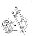
- FIG. 1 designates the support frame with a support frame which contains the individual elements of the device, the electroplating drum, the drive unit and the support arms.
- Transport receptacles 4 are arranged on the supporting frame and serve to lower or lift the device into the respective electrolyte or rinsing baths.
- the encapsulated drive motor 3 is arranged in the support frame and is suspended in an electrically insulated manner and has a gas-tight shaft feed 5. At the end a drive gear 6 is arranged on the shaft, which preferably consists of polyphenylene sulfide.
- the electroplating drum 13, which preferably consists of glass fiber reinforced polyphenylene sulfide, is driven via these drive gearwheels.
- the electroplating drum 13 is connected to the support frame 1 via the support arms 11.
- the support arms 11 are preferably made of stainless steel, are hollow and coated on the outside with fluorine-containing polymers. In the cavity of the support arms 11 there is insulation material in which the busbars for the electrolysis current are arranged 9, 10.
- the number 12 denotes the bearing block for the electroplating drum.
- the electroplating drum has perforated side walls 14 and a perforated inner tube 15 which is open on the side.
- An inner auxiliary anode 17 can preferably be introduced through this tube into the drum in order to achieve higher electrolyte concentrations on the coating material.
- the number 18 designates the removal contacts arranged in the drum, which preferably consist of copper.
- Flexible power transmission contacts 16 are also located inside the electroplating drum.
- the number 9 designates the power supply line for the coating material. This is isolated inside the drum holder.
- the number 7 designates the inert gas ventilation of the housing of the drive unit with check valve.
- the device according to the invention With the device according to the invention, high-quality coatings with aluminum or aluminum alloys can be carried out. Coatings with magnesium and magnesium alloys are also possible, in which case the corresponding magnesium alkyl-containing electrolytes are used.
- the device according to the invention is long-lasting and can also be used in aqueous systems, for example for rinsing processes.
Landscapes
- Chemical & Material Sciences (AREA)
- Engineering & Computer Science (AREA)
- Chemical Kinetics & Catalysis (AREA)
- Electrochemistry (AREA)
- Materials Engineering (AREA)
- Metallurgy (AREA)
- Organic Chemistry (AREA)
- Electroplating Methods And Accessories (AREA)
- Electroplating And Plating Baths Therefor (AREA)
- Prevention Of Electric Corrosion (AREA)
- Primary Cells (AREA)
- Vehicle Body Suspensions (AREA)
Priority Applications (15)
| Application Number | Priority Date | Filing Date | Title |
|---|---|---|---|
| EP01118392A EP1279751A1 (fr) | 2001-07-28 | 2001-07-28 | Appareil pour la deposition d' aluminium ou d'alliage d'aluminium à partir des electrolytes contenant des alkyles d'aluminium |
| RU2004105960/02A RU2287619C2 (ru) | 2001-07-28 | 2002-07-26 | Устройство для электроосаждения алюминия или алюминиевых сплавов из металлорганических электролитов, содержащих алкилалюминий |
| BR0211467-4A BR0211467A (pt) | 2001-07-28 | 2002-07-26 | Dispositivo para eletrodeposição de alumìnio e ou ligas de alumìnio a partir de eletrólitos organometálicos |
| CZ20040141A CZ297865B6 (cs) | 2001-07-28 | 2002-07-26 | Zarízení pro galvanické vylucování hliníku a/neboslitin z hliníku z organokovových elektrolytu |
| EP02791472A EP1412562B1 (fr) | 2001-07-28 | 2002-07-26 | Procede de separation galvanique de l'aluminium ou d'alliages d'aluminium a partir d'electrolytes organometalliques renfermant des alkyl-aluminium |
| JP2003517345A JP4149919B2 (ja) | 2001-07-28 | 2002-07-26 | アルキルアルミニウムを含む有機金属電解液からのアルミニウムまたはアルミニウム合金の電着のための装置 |
| KR1020047001226A KR100867354B1 (ko) | 2001-07-28 | 2002-07-26 | 알킬알루미늄을 함유하는 유기금속 전해질로부터 알루미늄또는 알루미늄 합금을 전해석출하는 장치 |
| DE50202333T DE50202333D1 (de) | 2001-07-28 | 2002-07-26 | Vorrichtung zum galvanischen abscheiden von aluminum oder aluminiumlegierungen aus metallorganischen aluminiumalkylhaltigen elektrolyten |
| CA002454075A CA2454075A1 (fr) | 2001-07-28 | 2002-07-26 | Procede de separation galvanique de l'aluminium ou d'alliages d'aluminium a partir d'electrolytes organometalliques renfermant des alkyl-aluminium |
| AT02791472T ATE289635T1 (de) | 2001-07-28 | 2002-07-26 | Vorrichtung zum galvanischen abscheiden von aluminum oder aluminiumlegierungen aus metallorganischen aluminiumalkylhaltigen elektrolyten |
| US10/485,325 US20040256219A1 (en) | 2001-07-28 | 2002-07-26 | Device for the electrodeposition of aluminum or aluminum alloys from organometallic electrolytes containing alkyl |
| PCT/EP2002/008329 WO2003012176A1 (fr) | 2001-07-28 | 2002-07-26 | Procede de separation galvanique de l'aluminium ou d'alliages d'aluminium a partir d'electrolytes organometalliques renfermant des alkyl-aluminium |
| MXPA04000859A MXPA04000859A (es) | 2001-07-28 | 2002-07-26 | Un dispositivo para la electrodeposicion de aluminio o aleaciones de aluminio a partir de electrolitos organometalicos que contienen alquilaluminio. |
| CNB02814628XA CN1283850C (zh) | 2001-07-28 | 2002-07-26 | 从金属有机的含烷基铝的电解液中电沉积铝或铝合金的装置 |
| NO20040373A NO20040373L (no) | 2001-07-28 | 2004-01-27 | Anordning for elektroavsetning av aluminium eller aluminiumslegeringer fra organometalliske elektrolytter inneholdende alkylaluminium |
Applications Claiming Priority (1)
| Application Number | Priority Date | Filing Date | Title |
|---|---|---|---|
| EP01118392A EP1279751A1 (fr) | 2001-07-28 | 2001-07-28 | Appareil pour la deposition d' aluminium ou d'alliage d'aluminium à partir des electrolytes contenant des alkyles d'aluminium |
Publications (1)
| Publication Number | Publication Date |
|---|---|
| EP1279751A1 true EP1279751A1 (fr) | 2003-01-29 |
Family
ID=8178187
Family Applications (2)
| Application Number | Title | Priority Date | Filing Date |
|---|---|---|---|
| EP01118392A Withdrawn EP1279751A1 (fr) | 2001-07-28 | 2001-07-28 | Appareil pour la deposition d' aluminium ou d'alliage d'aluminium à partir des electrolytes contenant des alkyles d'aluminium |
| EP02791472A Expired - Lifetime EP1412562B1 (fr) | 2001-07-28 | 2002-07-26 | Procede de separation galvanique de l'aluminium ou d'alliages d'aluminium a partir d'electrolytes organometalliques renfermant des alkyl-aluminium |
Family Applications After (1)
| Application Number | Title | Priority Date | Filing Date |
|---|---|---|---|
| EP02791472A Expired - Lifetime EP1412562B1 (fr) | 2001-07-28 | 2002-07-26 | Procede de separation galvanique de l'aluminium ou d'alliages d'aluminium a partir d'electrolytes organometalliques renfermant des alkyl-aluminium |
Country Status (14)
| Country | Link |
|---|---|
| US (1) | US20040256219A1 (fr) |
| EP (2) | EP1279751A1 (fr) |
| JP (1) | JP4149919B2 (fr) |
| KR (1) | KR100867354B1 (fr) |
| CN (1) | CN1283850C (fr) |
| AT (1) | ATE289635T1 (fr) |
| BR (1) | BR0211467A (fr) |
| CA (1) | CA2454075A1 (fr) |
| CZ (1) | CZ297865B6 (fr) |
| DE (1) | DE50202333D1 (fr) |
| MX (1) | MXPA04000859A (fr) |
| NO (1) | NO20040373L (fr) |
| RU (1) | RU2287619C2 (fr) |
| WO (1) | WO2003012176A1 (fr) |
Cited By (2)
| Publication number | Priority date | Publication date | Assignee | Title |
|---|---|---|---|---|
| EP1524336A1 (fr) * | 2003-10-18 | 2005-04-20 | Aluminal Oberflächtentechnik GmbH & Co. KG | Pièces à usiner recouvertes d'un alliage aluminium-magnesium |
| EP1743959A1 (fr) | 2005-07-15 | 2007-01-17 | Aluminal Oberflächentechnik GmbH & Co. KG | Procédé de déposition galvanique de métaux ou d'alliages de métaux au moyen d'un tonneau de galvanisation |
Families Citing this family (2)
| Publication number | Priority date | Publication date | Assignee | Title |
|---|---|---|---|---|
| CN102817053B (zh) * | 2012-09-14 | 2016-03-09 | 昆山拓安塑料制品有限公司 | 一种提高产品镀铝效率的防护工装 |
| EP2813602A1 (fr) * | 2013-06-14 | 2014-12-17 | ATOTECH Deutschland GmbH | "Dispositif de maintien d'un support de substrat pour dépôt de métal galvanique vertical sur un substrat à traiter ; support de substrat pour être inséré dans un tel dispositif " |
Citations (12)
| Publication number | Priority date | Publication date | Assignee | Title |
|---|---|---|---|---|
| US3479272A (en) * | 1966-08-09 | 1969-11-18 | Paul W Sandrock | Apparatus for plating,blackening,pickling,stripping and the like |
| CH537984A (fr) * | 1971-05-13 | 1973-06-15 | Universo Sa | Installation de placage galvanoplastique |
| US3767554A (en) * | 1971-06-08 | 1973-10-23 | Westlake Plastics Co | Plastic electroplating barrel |
| JPS5031861B1 (fr) * | 1970-07-09 | 1975-10-15 | ||
| US3969212A (en) * | 1975-04-03 | 1976-07-13 | The Albert Singleton Corporation | Reinforced hanger bracket for electroplating barrel and method of reinforcing a plastic bar |
| US4287672A (en) * | 1978-08-18 | 1981-09-08 | Hans Henig | Process and apparatus for drying pieces in bulk in a plating barrel |
| EP0209015A1 (fr) * | 1985-07-09 | 1987-01-21 | Siemens Aktiengesellschaft | Dispositif de traitement électrolytique d'objets en vrac |
| US4994163A (en) * | 1990-05-10 | 1991-02-19 | Lin Sheng R | Rotatable wastewater metal-reclaimation device |
| DE19519492A1 (de) * | 1995-05-27 | 1996-11-28 | Miele & Cie | Tragvorrichtung für metallische Werkstücke |
| DE19541231A1 (de) * | 1995-11-06 | 1997-05-07 | Hans Henig | Trommelaggregat |
| EP0857516A2 (fr) * | 1997-02-11 | 1998-08-12 | Protective Finishing Group Limited | Procédé et dispositif de revêtement d'objets |
| DE29818476U1 (de) * | 1998-10-16 | 1999-01-14 | Linnhoff & Pasternak Gmbh | Be- und Entladevorrichtung zur galvanischen Oberflächenbehandlung von Teilen in Bädern |
Family Cites Families (12)
| Publication number | Priority date | Publication date | Assignee | Title |
|---|---|---|---|---|
| US3467272A (en) * | 1968-04-18 | 1969-09-16 | Sterling Seal Co | Screw threaded closure for a container |
| US3824115A (en) * | 1969-06-12 | 1974-07-16 | Kureha Chemical Ind Co Ltd | Polyvinylidene fluoride composition and coating thereof |
| CH603832A5 (fr) * | 1975-08-21 | 1978-08-31 | Siemens Ag | |
| US4242192A (en) * | 1979-09-06 | 1980-12-30 | The United States Of America As Represented By The Secretary Of The Interior | Electrolytic stripping cell |
| DE3023129C2 (de) * | 1980-06-20 | 1982-04-15 | Siemens AG, 1000 Berlin und 8000 München | Vorrichtung zum galvanischen Abscheiden von Aluminium |
| DE3236138A1 (de) * | 1982-09-29 | 1984-03-29 | Siemens AG, 1000 Berlin und 8000 München | Vorrichtung zum galvanischen abscheiden von aluminium |
| US4571291A (en) * | 1984-08-20 | 1986-02-18 | Alumatec, Inc. | Apparatus for the electrodeposition of metal |
| EP0220419B1 (fr) * | 1985-09-17 | 1989-01-25 | Siemens Aktiengesellschaft | Installation de traitement électrolytique de pièces en vrac |
| JPH07100762B2 (ja) * | 1985-12-12 | 1995-11-01 | 東ソー株式会社 | メツキ用ポリフエニレンスルフイド樹脂組成物 |
| US5141615A (en) * | 1990-07-16 | 1992-08-25 | Nisshin Steel Co., Ltd. | Aluminum electroplating apparatus |
| DE29518476U1 (de) * | 1995-11-21 | 1996-02-15 | Eberleh Heinz Dieter | Faserfreier Dämmstoff zur Wärmeisolierung |
| US6355146B1 (en) * | 1996-04-03 | 2002-03-12 | The Regents Of The University Of California | Sputtering process and apparatus for coating powders |
-
2001
- 2001-07-28 EP EP01118392A patent/EP1279751A1/fr not_active Withdrawn
-
2002
- 2002-07-26 BR BR0211467-4A patent/BR0211467A/pt not_active Application Discontinuation
- 2002-07-26 RU RU2004105960/02A patent/RU2287619C2/ru not_active IP Right Cessation
- 2002-07-26 CZ CZ20040141A patent/CZ297865B6/cs not_active IP Right Cessation
- 2002-07-26 CA CA002454075A patent/CA2454075A1/fr not_active Abandoned
- 2002-07-26 JP JP2003517345A patent/JP4149919B2/ja not_active Expired - Fee Related
- 2002-07-26 WO PCT/EP2002/008329 patent/WO2003012176A1/fr active IP Right Grant
- 2002-07-26 US US10/485,325 patent/US20040256219A1/en not_active Abandoned
- 2002-07-26 DE DE50202333T patent/DE50202333D1/de not_active Expired - Lifetime
- 2002-07-26 EP EP02791472A patent/EP1412562B1/fr not_active Expired - Lifetime
- 2002-07-26 KR KR1020047001226A patent/KR100867354B1/ko not_active IP Right Cessation
- 2002-07-26 AT AT02791472T patent/ATE289635T1/de not_active IP Right Cessation
- 2002-07-26 CN CNB02814628XA patent/CN1283850C/zh not_active Expired - Fee Related
- 2002-07-26 MX MXPA04000859A patent/MXPA04000859A/es active IP Right Grant
-
2004
- 2004-01-27 NO NO20040373A patent/NO20040373L/no not_active Application Discontinuation
Patent Citations (12)
| Publication number | Priority date | Publication date | Assignee | Title |
|---|---|---|---|---|
| US3479272A (en) * | 1966-08-09 | 1969-11-18 | Paul W Sandrock | Apparatus for plating,blackening,pickling,stripping and the like |
| JPS5031861B1 (fr) * | 1970-07-09 | 1975-10-15 | ||
| CH537984A (fr) * | 1971-05-13 | 1973-06-15 | Universo Sa | Installation de placage galvanoplastique |
| US3767554A (en) * | 1971-06-08 | 1973-10-23 | Westlake Plastics Co | Plastic electroplating barrel |
| US3969212A (en) * | 1975-04-03 | 1976-07-13 | The Albert Singleton Corporation | Reinforced hanger bracket for electroplating barrel and method of reinforcing a plastic bar |
| US4287672A (en) * | 1978-08-18 | 1981-09-08 | Hans Henig | Process and apparatus for drying pieces in bulk in a plating barrel |
| EP0209015A1 (fr) * | 1985-07-09 | 1987-01-21 | Siemens Aktiengesellschaft | Dispositif de traitement électrolytique d'objets en vrac |
| US4994163A (en) * | 1990-05-10 | 1991-02-19 | Lin Sheng R | Rotatable wastewater metal-reclaimation device |
| DE19519492A1 (de) * | 1995-05-27 | 1996-11-28 | Miele & Cie | Tragvorrichtung für metallische Werkstücke |
| DE19541231A1 (de) * | 1995-11-06 | 1997-05-07 | Hans Henig | Trommelaggregat |
| EP0857516A2 (fr) * | 1997-02-11 | 1998-08-12 | Protective Finishing Group Limited | Procédé et dispositif de revêtement d'objets |
| DE29818476U1 (de) * | 1998-10-16 | 1999-01-14 | Linnhoff & Pasternak Gmbh | Be- und Entladevorrichtung zur galvanischen Oberflächenbehandlung von Teilen in Bädern |
Non-Patent Citations (1)
| Title |
|---|
| DATABASE WPI Section Ch Week 197545, Derwent World Patents Index; Class M13, AN 1975-75078W, XP002185826 * |
Cited By (4)
| Publication number | Priority date | Publication date | Assignee | Title |
|---|---|---|---|---|
| EP1524336A1 (fr) * | 2003-10-18 | 2005-04-20 | Aluminal Oberflächtentechnik GmbH & Co. KG | Pièces à usiner recouvertes d'un alliage aluminium-magnesium |
| WO2005035835A2 (fr) * | 2003-10-18 | 2005-04-21 | Aluminal Oberflächentechnik Gmbh & Co. Kg | Pieces a usiner enduites d'un alliage aluminium-magnesium |
| WO2005035835A3 (fr) * | 2003-10-18 | 2005-06-23 | Aluminal Oberflaechentechnik | Pieces a usiner enduites d'un alliage aluminium-magnesium |
| EP1743959A1 (fr) | 2005-07-15 | 2007-01-17 | Aluminal Oberflächentechnik GmbH & Co. KG | Procédé de déposition galvanique de métaux ou d'alliages de métaux au moyen d'un tonneau de galvanisation |
Also Published As
| Publication number | Publication date |
|---|---|
| WO2003012176A1 (fr) | 2003-02-13 |
| JP4149919B2 (ja) | 2008-09-17 |
| KR20040035696A (ko) | 2004-04-29 |
| DE50202333D1 (de) | 2005-03-31 |
| JP2004537650A (ja) | 2004-12-16 |
| US20040256219A1 (en) | 2004-12-23 |
| NO20040373L (no) | 2004-03-26 |
| KR100867354B1 (ko) | 2008-11-07 |
| CN1533451A (zh) | 2004-09-29 |
| RU2287619C2 (ru) | 2006-11-20 |
| EP1412562B1 (fr) | 2005-02-23 |
| BR0211467A (pt) | 2004-08-17 |
| ATE289635T1 (de) | 2005-03-15 |
| CZ2004141A3 (cs) | 2004-12-15 |
| CN1283850C (zh) | 2006-11-08 |
| CA2454075A1 (fr) | 2003-02-13 |
| CZ297865B6 (cs) | 2007-04-18 |
| RU2004105960A (ru) | 2005-05-10 |
| EP1412562A1 (fr) | 2004-04-28 |
| MXPA04000859A (es) | 2005-06-20 |
Similar Documents
| Publication | Publication Date | Title |
|---|---|---|
| DE60018764T2 (de) | Verfahren zum kontinuierlichen vernickeln eines aluminium-leiters und vorrichtung dazu | |
| DE2537256C3 (de) | Vorrichtung zum galvanischen Abscheiden von Aluminium | |
| US4066515A (en) | Apparatus and method for the electrodepositing of aluminum | |
| EP1412562B1 (fr) | Procede de separation galvanique de l'aluminium ou d'alliages d'aluminium a partir d'electrolytes organometalliques renfermant des alkyl-aluminium | |
| EP0042503B1 (fr) | Appareillage pour le dépôt d'aluminium par voie électrolytique | |
| DE2716805C3 (de) | Vorrichtung zum galvanischen Abscheiden von Aluminium | |
| EP0070011B1 (fr) | Dispositif de galvanisation | |
| CH694619A5 (de) | Verfahren und Vorrichtung zur elektrochemischen Behandlung. | |
| DE3044975A1 (de) | Vorrichtung zum galvanischen abscheiden von aluminium | |
| DE3023405C2 (de) | Vorrichtung und Verfahren zum galvanischen Abscheiden von Aluminium | |
| DE19932524C1 (de) | Verfahren und Vorrichtung zur elektrochemischen Behandlung | |
| DE19932523C1 (de) | Verfahren und Vorrichtung zur elektrochemischen Behandlung | |
| DE1621097A1 (de) | Verfahren und Vorrichtung zur elektrolytischen Herstellung von langgestreckten Metallgegenstaenden,insbesondere von Draehten | |
| EP0975826B1 (fr) | Procede de revetement electrolytique de produits continus metalliques ou non metalliques et dispositif pour la mise en oeuvre de ce procede | |
| DE19632132C1 (de) | Verfahren zur elektrochemischen Behandlung von stabförmigem Behandlungsgut und Vorrichtung zur Durchführung des Verfahrens | |
| EP0043440A1 (fr) | Appareillage pour le dépôt d'aluminium, par voie électrolytique | |
| DE2815761A1 (de) | Vorrichtung zur behandlung der innenflaechen von metallischen rohren | |
| DE69927295T2 (de) | Verfahren zur herstellung von kupferrohren mit innenoberflächen, die mittels elektrolyse zinn plattiert sind | |
| DE3102021A1 (de) | Vorrichtung zum galvanischen abscheiden von aluminium | |
| DE2443361C3 (de) | Einrichtung zum Galvanisieren von Werkstücken in unter Schutzgas betriebenen Badbehältern | |
| DE1421971A1 (de) | Verfahren und Vorrichtung zur elektrochemischen Behandlung von Werkstuecken | |
| DE2443361B2 (de) | Einrichtung zum galvanisieren von werkstuecken in unter schutzgas betriebenen badbehaeltern |
Legal Events
| Date | Code | Title | Description |
|---|---|---|---|
| PUAI | Public reference made under article 153(3) epc to a published international application that has entered the european phase |
Free format text: ORIGINAL CODE: 0009012 |
|
| AK | Designated contracting states |
Designated state(s): AT BE CH CY DE DK ES FI FR GB GR IE IT LI LU MC NL PT SE TR |
|
| AX | Request for extension of the european patent |
Extension state: AL LT LV MK RO SI |
|
| AKX | Designation fees paid | ||
| REG | Reference to a national code |
Ref country code: DE Ref legal event code: 8566 |
|
| STAA | Information on the status of an ep patent application or granted ep patent |
Free format text: STATUS: THE APPLICATION IS DEEMED TO BE WITHDRAWN |
|
| 18D | Application deemed to be withdrawn |
Effective date: 20030730 |