EP1278694B1 - Lastaufnahmemittel für seil-aufzüge mit integrierter lastmesseinrichtung - Google Patents
Lastaufnahmemittel für seil-aufzüge mit integrierter lastmesseinrichtung Download PDFInfo
- Publication number
- EP1278694B1 EP1278694B1 EP01921103A EP01921103A EP1278694B1 EP 1278694 B1 EP1278694 B1 EP 1278694B1 EP 01921103 A EP01921103 A EP 01921103A EP 01921103 A EP01921103 A EP 01921103A EP 1278694 B1 EP1278694 B1 EP 1278694B1
- Authority
- EP
- European Patent Office
- Prior art keywords
- load
- cable
- carrying means
- measurement device
- integrated
- Prior art date
- Legal status (The legal status is an assumption and is not a legal conclusion. Google has not performed a legal analysis and makes no representation as to the accuracy of the status listed.)
- Expired - Lifetime
Links
- 238000005259 measurement Methods 0.000 title claims 8
- 238000005452 bending Methods 0.000 claims description 23
- 230000001419 dependent effect Effects 0.000 claims description 2
- 238000006073 displacement reaction Methods 0.000 claims 1
- 230000001939 inductive effect Effects 0.000 claims 1
- 238000009434 installation Methods 0.000 description 3
- 239000000725 suspension Substances 0.000 description 3
- 238000010276 construction Methods 0.000 description 2
- 238000011156 evaluation Methods 0.000 description 2
- 238000009413 insulation Methods 0.000 description 2
- 230000005540 biological transmission Effects 0.000 description 1
- 238000001514 detection method Methods 0.000 description 1
- 230000007613 environmental effect Effects 0.000 description 1
- 238000002955 isolation Methods 0.000 description 1
Images
Classifications
-
- B—PERFORMING OPERATIONS; TRANSPORTING
- B66—HOISTING; LIFTING; HAULING
- B66B—ELEVATORS; ESCALATORS OR MOVING WALKWAYS
- B66B1/00—Control systems of elevators in general
- B66B1/34—Details, e.g. call counting devices, data transmission from car to control system, devices giving information to the control system
- B66B1/3476—Load weighing or car passenger counting devices
- B66B1/3484—Load weighing or car passenger counting devices using load cells
Definitions
- the present invention relates to a load-handling device for cable lifts with integrated load measuring device, in which the weight of load-carrying means and payload causes the load-proportional deformation of at least one elastic element, wherein at least one sensor detects this deformation and a strength of the deformation and thus the load representing Generates signal to an elevator control.
- Load measuring devices for load-handling devices of elevators have the task of preventing an elevator travel with an unacceptably high load and to provide the elevator control with information that allows it to respond to call commands by elevator users in a suitable manner, depending on the current load condition of the load handling device.
- EP 0 151 949 discloses a load-sensing device for an elevator elevator, which is based on the principle that the entire elevator car is supported on at least four horizontally projecting from an elevator floor frame bending beams, that these bending beams undergo a load-proportional deflection. The deflection of each individual bending beam is detected by means of strain gauges. All strain gauges together form a measuring bridge, which supplies a load-proportional analog signal to the elevator control.
- the described load measuring device has some disadvantages.
- the measuring principle requires four bending supports equipped with one or two strain gauges, whereby the mechanical tolerances of the bending beams as well as the resistance tolerances and mounting tolerances of the strain gauges are to be limited so tightly that all four bending sensors have the same resistance values for the same loads. All four or eight strain gauges are to be individually connected to a central evaluation circuit, which causes considerable expense. In addition, the four force introduction points between the bottom of the elevator car and the bending beams are to be adjusted vertically during installation so that an acceptable power distribution is ensured.
- the present invention has for its object to provide a simple and cost-effective load-measuring device for load-carrying means of lifts with underlayment cable drive, which does not have the disadvantages mentioned above.
- the inventive load-handling device for cable lifts with integrated load measuring device has significant advantages.
- the elastic horizontal bending beam, whose deformation caused by the weight of the lifting device is detected by the sensor, is the supporting structure with which the pulleys are attached to the load-carrying means. As a result, essentially no additional mechanical construction elements and no additional installation space for the load measuring device are required.
- the load-dependent deformation of the bending beam is detected by a sensor. This allows optimally adapted load measuring devices to be designed.
- inventions of the inventive load-carrying means with integrated load measuring device can be achieved by the use of adapted to geometric conditions, environmental influences and in particular to accuracy requirements sensor principles.
- the invention allows the use of a variety of sensors for detecting deformation, such as strain gauges, vibrating string sensors, opto-electrical distance or angle sensors and inductively or capacitively acting distance sensors.
- Load-bearing devices for larger loads are usually equipped with a support frame.
- load handling devices for smaller payloads, these can be designed as a self-supporting unit.
- the supporting structure (s) carrying the sheaves and containing the elastic bending beam are in this case advantageously fastened directly to the floor construction of the load receiving means.
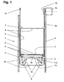
- FIG. 1 shows a carrying frame-free load-bearing means 1 according to the invention with the lift components most important for its function.
- two guide rails are referred to which by means of sliding or roller guide shoes 3, the load-carrying means is guided vertically.
- This consists essentially of a bottom frame 4 with bottom plate 5, a built thereon cabin 6, said sliding or roller guide shoes 3 and two by means of a support structure 7 via elastic isolation elements 8 on the bottom frame 4 fixed pulleys 9.
- the support structure 7 consists of a bending beam 7.1 and two pulley supports 7.2.
- a support cable 10 which is guided vertically downwards from a cable fix point 11, then horizontally under the pulleys 9 of the load-receiving means 1 and then vertically upwards to a traction sheave 12 of an elevator drive machine 13. Not shown here is the further course of the support cable 10 from the traction sheave 12 down to a mounted on a balance weight deflecting plate and from there upwards to a second rope set point.
- each of the two pulleys 9 each acts a vertical and horizontal load-proportional cable traction.
- the arrows 14 symbolize the on the pulleys 9 and thus on the Support structure 7 acting, resulting from the Seilkzugräften the suspension cables pulley loads. It is readily apparent that these resultant in the bending beam 7.1 of the support structure 7 generate a bending moment and thus a deflection.
- This deflection is detected by a bending sensor 15, for example a strain gauge sensor, which is not explained here in more detail, and generates a signal corresponding to the magnitude of the deflection and thus the total weight of the load receiving means 1 as input for an elevator control.
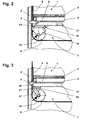
- Fig. 2 is a variant of a load-carrying means with integrated load measuring device shown. Visible are the means of sliding or roller guide shoe 3 guided on guide rails 2 load-carrying means 1 with bottom frame 4, bottom plate 5 and cab 6.
- the supporting the pulleys 9 support structure 7 consists essentially of one, via elastic insulation elements 8 on the bottom frame 4 mounted mounting bracket 17 and two Pulley Supports 18.
- the pulley support, not shown here, arranged on the right corresponds to the pulley supports according to FIG Fig. 1 ,
- the left-side pulley support 18 is articulated by means of a bending element 19 on the mounting bracket 17 and supported by a pressure sensor 16 with respect to this.
- the articulated attachment of the pulley support 18 could also be achieved with a hinge axis.
- the resulting from the Seilkzugräften the suspension cables pulley load 14 causes a load-proportional pressure force on the pressure sensor 16, which also forms the elastic element, and generates a the total weight of the load receiving means 1 corresponding signal as input for an elevator control.
- the pressure sensor can be designed, for example, as a piezoelectric element, as a capacitive sensor or as a strain gauge element.
- Fig. 3 shows a further variant of a lifting device with integrated load measuring device. Visible are in turn guided by means of sliding or roller guide shoe 3 on guide rails 2 load-carrying means 1 with bottom frame 4, bottom plate 5 and cab 6.
- the supporting the pulleys 9 support structure 7 consists essentially of one, via elastic insulation elements 8 mounted on the bottom frame 4 with a left-side Bearing support 20 and two pulley supports.
- the not shown here, right arranged pulley support corresponds to the pulley supports according Fig. 1
- the left-side, designed as a pivot lever pulley support 21 shown here is attached to a torsion bar 22 and rotatably mounted on this in the associated with the mounting bracket 17 bearing support 20.
- a stop 23 prevents overloading of the torsion bar 22. This is extended beyond the bearing support 20 to the rear (in the drawing plane) and connected at its rear end against rotation with the mounting bracket 17.
- the resulting from the Seilkzugräften the suspension cables pulley load 14 causes via the designed as a pivot lever pulley support 21 a load proportional torque, which twists the torsion bar 22 and causes in this corresponding load-proportional torsional stresses.
- a Verwars sensor in the form of strain gauges
Landscapes
- Engineering & Computer Science (AREA)
- Automation & Control Theory (AREA)
- Mechanical Engineering (AREA)
- Computer Networks & Wireless Communication (AREA)
- Maintenance And Inspection Apparatuses For Elevators (AREA)
- Elevator Control (AREA)
- Lift-Guide Devices, And Elevator Ropes And Cables (AREA)
- Cage And Drive Apparatuses For Elevators (AREA)
- Force Measurement Appropriate To Specific Purposes (AREA)
- Electrical Discharge Machining, Electrochemical Machining, And Combined Machining (AREA)
- Forklifts And Lifting Vehicles (AREA)
- Grinding Of Cylindrical And Plane Surfaces (AREA)
Priority Applications (2)
| Application Number | Priority Date | Filing Date | Title |
|---|---|---|---|
| EP01921103A EP1278694B1 (de) | 2000-05-01 | 2001-04-26 | Lastaufnahmemittel für seil-aufzüge mit integrierter lastmesseinrichtung |
| HK03104981.0A HK1055590B (zh) | 2000-05-01 | 2001-04-26 | 含有综合负载测量装置的钢缆操作电梯的承重方法 |
Applications Claiming Priority (4)
| Application Number | Priority Date | Filing Date | Title |
|---|---|---|---|
| EP00810371 | 2000-05-01 | ||
| EP00810371 | 2000-05-01 | ||
| EP01921103A EP1278694B1 (de) | 2000-05-01 | 2001-04-26 | Lastaufnahmemittel für seil-aufzüge mit integrierter lastmesseinrichtung |
| PCT/CH2001/000625 WO2002032565A1 (en) | 2000-10-19 | 2001-04-26 | Reactor |
Publications (2)
| Publication Number | Publication Date |
|---|---|
| EP1278694A1 EP1278694A1 (de) | 2003-01-29 |
| EP1278694B1 true EP1278694B1 (de) | 2012-12-26 |
Family
ID=8174674
Family Applications (1)
| Application Number | Title | Priority Date | Filing Date |
|---|---|---|---|
| EP01921103A Expired - Lifetime EP1278694B1 (de) | 2000-05-01 | 2001-04-26 | Lastaufnahmemittel für seil-aufzüge mit integrierter lastmesseinrichtung |
Country Status (19)
| Country | Link |
|---|---|
| US (1) | US6715587B2 (enExample) |
| EP (1) | EP1278694B1 (enExample) |
| JP (1) | JP5044079B2 (enExample) |
| KR (1) | KR20030003269A (enExample) |
| CN (1) | CN1218864C (enExample) |
| AU (1) | AU784531B2 (enExample) |
| BR (1) | BR0110436B1 (enExample) |
| CA (1) | CA2406896C (enExample) |
| CZ (1) | CZ298166B6 (enExample) |
| ES (1) | ES2401773T3 (enExample) |
| HK (1) | HK1055590B (enExample) |
| HU (1) | HU226605B1 (enExample) |
| MX (1) | MXPA02010660A (enExample) |
| NO (1) | NO322985B1 (enExample) |
| PL (1) | PL205025B1 (enExample) |
| RU (1) | RU2271327C2 (enExample) |
| SK (1) | SK286344B6 (enExample) |
| WO (1) | WO2001083350A1 (enExample) |
| ZA (1) | ZA200208701B (enExample) |
Cited By (2)
| Publication number | Priority date | Publication date | Assignee | Title |
|---|---|---|---|---|
| WO2021084012A1 (de) | 2019-10-31 | 2021-05-06 | Inventio Ag | Bremsvorrichtung für eine aufzugkabine mit integrierter lastmesseinrichtung und deren verwendung in einer aufzuganlage und verfahren |
| WO2022144322A1 (de) | 2020-12-31 | 2022-07-07 | Inventio Ag | Aufhängevorrichtung und deren verwendung in einer aufzugsanlage und verfahren |
Families Citing this family (36)
| Publication number | Priority date | Publication date | Assignee | Title |
|---|---|---|---|---|
| SG123668A1 (en) * | 2004-12-10 | 2006-07-26 | Inventio Ag | Pulley arrangement for elevators |
| FI120763B (fi) | 2006-06-05 | 2010-02-26 | Kone Corp | Menetelmä kuorman mittaamiseksi hississä ja hissi |
| US7784589B2 (en) * | 2006-07-10 | 2010-08-31 | Inventio Ag | Elevator lift cage load measuring assembly |
| TWI394705B (zh) * | 2007-02-02 | 2013-05-01 | Inventio Ag | 升降機及監視此升降機之方法 |
| CN101298307B (zh) | 2007-05-03 | 2010-06-23 | 因温特奥股份公司 | 电梯设备,电梯设备用转向辊,和设置负载传感器的方法 |
| US8430211B2 (en) * | 2007-06-08 | 2013-04-30 | Otis Elevator Company | Elevator system with guide axis aligned with traction member |
| FI20070539L (fi) * | 2007-07-09 | 2009-01-10 | Kone Corp | Hissijärjestelmä |
| US8162110B2 (en) * | 2008-06-19 | 2012-04-24 | Thyssenkrupp Elevator Capital Corporation | Rope tension equalizer and load monitor |
| ES2438740T3 (es) * | 2009-04-20 | 2014-01-20 | Inventio Ag | Monitorización del estado de funcionamiento de medios portantes en una instalación de ascensor |
| ES2524399T3 (es) * | 2010-04-19 | 2014-12-09 | Inventio Ag | Vigilancia del estado de funcionamiento de los elementos de suspensión en una instalación de ascensor |
| CH703134A2 (it) * | 2010-05-14 | 2011-11-15 | Kone Corp | Sistema per la rilevazione del carico nella cabina di un ascensore. |
| WO2012031961A1 (de) | 2010-09-09 | 2012-03-15 | Inventio Ag | Lastmesseinrichtung für eine aufzugsanlage |
| JP5776424B2 (ja) * | 2011-08-03 | 2015-09-09 | フジテック株式会社 | エレベータ装置 |
| US9522806B2 (en) * | 2012-06-29 | 2016-12-20 | Inventio Ag | Deflection pulley cover for monitoring elevator car support |
| CN102910514B (zh) * | 2012-11-01 | 2015-03-04 | 日立电梯(中国)有限公司 | 一种电梯轿厢称重系统及称重方法 |
| CN103342273A (zh) * | 2013-07-11 | 2013-10-09 | 上海振华重工(集团)股份有限公司 | 多倍率滑轮组的秤重装置 |
| JP5976223B2 (ja) * | 2013-08-02 | 2016-08-23 | 三菱電機株式会社 | せり上げ式エレベータ |
| CN103552894B (zh) * | 2013-11-14 | 2016-08-17 | 日立电梯(中国)有限公司 | 轿底称重结构及包含该轿底称重结构的电梯 |
| EP3000758B1 (en) * | 2014-09-25 | 2019-04-17 | KONE Corporation | Method for balancing an elevator car |
| DE102014220445B4 (de) * | 2014-10-09 | 2017-06-08 | Thyssenkrupp Ag | Vorrichtung zur Überprüfung von Führungen |
| US20170341907A1 (en) * | 2014-12-18 | 2017-11-30 | Inventio Ag | Electrical energy generation within an elevator installation |
| CN104528497B (zh) * | 2014-12-23 | 2016-11-02 | 林肯电梯(中国)有限公司 | 一种高压曳引机 |
| CN105984773B (zh) * | 2015-02-28 | 2020-06-12 | 通力股份公司 | 用于检测多个电梯绳索的总载荷的绳索载荷检测装置 |
| JP6224643B2 (ja) * | 2015-03-26 | 2017-11-01 | 日本碍子株式会社 | 棚板割れ検知方法、ハニカム構造体の搬送方法、棚板割れ検知装置、及び棚板搬送装置 |
| RU2618862C2 (ru) * | 2015-10-12 | 2017-05-11 | Общество с ограниченной ответственностью "ФИРМА ПОДИЙ" ООО "ФИРМА ПОДИЙ" | Способ контроля параметров движения подъемного устройства |
| EP3601131B1 (en) * | 2017-03-31 | 2022-05-11 | Inventio AG | Elevator car load measurement system and method for determining a load of an elevator car |
| DE102017219304A1 (de) * | 2017-10-27 | 2019-05-02 | Contitech Antriebssysteme Gmbh | Verfahren und Vorrichtung zur Bestimmung der Zugkraft in einem Trag-, Förder- oder Zugmittel |
| EP3705435B1 (en) * | 2019-03-05 | 2021-09-15 | KONE Corporation | A combined elevator vibration isolation and load measurement element |
| CN109795928A (zh) * | 2019-03-13 | 2019-05-24 | 日立电梯(中国)有限公司 | 电梯轿厢、运行控制方法和电梯 |
| CN110626907B (zh) * | 2019-07-25 | 2023-07-25 | 山东奔速电梯股份有限公司 | 室内电梯的超载检测装置及使用该装置控制电梯的方法 |
| CN110697548B (zh) * | 2019-08-31 | 2021-04-06 | 上海汉神机电股份有限公司 | 一种阻止电梯轿厢体振动的减振系统及其工作方法 |
| CN110902535A (zh) * | 2020-01-02 | 2020-03-24 | 迅达(中国)电梯有限公司 | 无机房电梯轿厢 |
| CN118434665A (zh) | 2021-12-23 | 2024-08-02 | 因温特奥股份公司 | 用于电梯轿厢的制动装置及其在电梯设备中的用途以及方法 |
| WO2024245567A1 (en) * | 2023-06-02 | 2024-12-05 | Kone Corporation | Elevator pulley arrangement, elevator, and method of suspending elevator car |
| DE102024123983A1 (de) * | 2024-08-22 | 2025-07-17 | Tk Elevator Innovation And Operations Gmbh | Klebevorrichtung zum Aufkleben zumindest eines Codebands auf einen in einem Aufzugsschacht angeordneten Träger bei einer Aufzugsanlage |
| CN119573958A (zh) * | 2024-11-06 | 2025-03-07 | 上海卫星工程研究所 | 测量双超卫星星上电缆力矩和张力的装置 |
Family Cites Families (12)
| Publication number | Priority date | Publication date | Assignee | Title |
|---|---|---|---|---|
| JPS5344737B2 (enExample) * | 1972-12-01 | 1978-12-01 | ||
| CH663949A5 (de) | 1984-02-14 | 1988-01-29 | Inventio Ag | Lastmesseinrichtung fuer eine aufzugskabine. |
| FR2609974A1 (fr) * | 1987-01-27 | 1988-07-29 | Otis Elevator Co | Ascenseur a traction |
| FI84050C (fi) * | 1988-04-18 | 1991-10-10 | Kone Oy | Foerfarande foer kontroll av friktionen mellan drivskiva och baerlinor till en hiss. |
| SU1765091A2 (ru) * | 1990-12-25 | 1992-09-30 | Ульяновский научно-исследовательский и проектно-технологический институт машиностроения | Подъемник |
| JP3300061B2 (ja) * | 1991-11-15 | 2002-07-08 | オーチス エレベータ カンパニー | エレベータ車両の負荷計測用組立体 |
| US5435209A (en) * | 1992-06-26 | 1995-07-25 | Wittur Aufzugteile Gmbh & Co. | Drive unit for a hoisting apparatus, in particular for a passenger or freight elevator |
| FI93632C (fi) * | 1993-06-28 | 1995-05-10 | Kone Oy | Alakoneistoinen vetopyörähissi |
| WO1998029327A1 (en) * | 1996-12-30 | 1998-07-09 | Kone Corporation | Elevator rope arrangement |
| JPH11314868A (ja) * | 1998-04-28 | 1999-11-16 | Toshiba Elevator Co Ltd | 昇降機のかご荷重検出装置 |
| JP4131764B2 (ja) * | 1998-09-01 | 2008-08-13 | 東芝エレベータ株式会社 | エレベータ装置 |
| US6483047B1 (en) * | 2000-09-13 | 2002-11-19 | Otis Elevator Company | Elevator brake load weighing system |
-
2001
- 2001-04-26 PL PL358217A patent/PL205025B1/pl unknown
- 2001-04-26 JP JP2001580789A patent/JP5044079B2/ja not_active Expired - Fee Related
- 2001-04-26 ES ES01921103T patent/ES2401773T3/es not_active Expired - Lifetime
- 2001-04-26 MX MXPA02010660A patent/MXPA02010660A/es active IP Right Grant
- 2001-04-26 RU RU2002132265/03A patent/RU2271327C2/ru not_active IP Right Cessation
- 2001-04-26 HU HU0300349A patent/HU226605B1/hu not_active IP Right Cessation
- 2001-04-26 KR KR1020027014675A patent/KR20030003269A/ko not_active Ceased
- 2001-04-26 EP EP01921103A patent/EP1278694B1/de not_active Expired - Lifetime
- 2001-04-26 HK HK03104981.0A patent/HK1055590B/zh not_active IP Right Cessation
- 2001-04-26 CZ CZ20023840A patent/CZ298166B6/cs not_active IP Right Cessation
- 2001-04-26 WO PCT/CH2001/000265 patent/WO2001083350A1/de not_active Ceased
- 2001-04-26 AU AU48217/01A patent/AU784531B2/en not_active Ceased
- 2001-04-26 CA CA2406896A patent/CA2406896C/en not_active Expired - Lifetime
- 2001-04-26 SK SK1476-2002A patent/SK286344B6/sk not_active IP Right Cessation
- 2001-04-26 BR BRPI0110436-5A patent/BR0110436B1/pt not_active IP Right Cessation
- 2001-04-26 CN CNB018089119A patent/CN1218864C/zh not_active Expired - Fee Related
-
2002
- 2002-10-28 ZA ZA200208701A patent/ZA200208701B/en unknown
- 2002-10-30 US US10/283,782 patent/US6715587B2/en not_active Expired - Lifetime
- 2002-11-01 NO NO20025257A patent/NO322985B1/no unknown
Cited By (3)
| Publication number | Priority date | Publication date | Assignee | Title |
|---|---|---|---|---|
| WO2021084012A1 (de) | 2019-10-31 | 2021-05-06 | Inventio Ag | Bremsvorrichtung für eine aufzugkabine mit integrierter lastmesseinrichtung und deren verwendung in einer aufzuganlage und verfahren |
| US11772933B2 (en) | 2019-10-31 | 2023-10-03 | Inventio Ag | Brake device for an elevator car, comprising an integrated load measuring device, use thereof in an elevator system, and method |
| WO2022144322A1 (de) | 2020-12-31 | 2022-07-07 | Inventio Ag | Aufhängevorrichtung und deren verwendung in einer aufzugsanlage und verfahren |
Also Published As
| Publication number | Publication date |
|---|---|
| MXPA02010660A (es) | 2003-03-10 |
| RU2271327C2 (ru) | 2006-03-10 |
| CN1427798A (zh) | 2003-07-02 |
| CA2406896C (en) | 2010-01-26 |
| CZ20023840A3 (cs) | 2004-06-16 |
| HU226605B1 (en) | 2009-04-28 |
| CA2406896A1 (en) | 2001-11-08 |
| ZA200208701B (en) | 2003-10-28 |
| NO20025257D0 (no) | 2002-11-01 |
| SK286344B6 (en) | 2008-07-07 |
| NO322985B1 (no) | 2006-12-18 |
| AU784531B2 (en) | 2006-04-27 |
| AU4821701A (en) | 2001-11-12 |
| WO2001083350A1 (de) | 2001-11-08 |
| ES2401773T3 (es) | 2013-04-24 |
| PL205025B1 (pl) | 2010-03-31 |
| US20030111301A1 (en) | 2003-06-19 |
| HK1055590A1 (en) | 2004-01-16 |
| US6715587B2 (en) | 2004-04-06 |
| BR0110436B1 (pt) | 2009-08-11 |
| HUP0300349A2 (en) | 2003-06-28 |
| HK1055590B (zh) | 2013-06-14 |
| KR20030003269A (ko) | 2003-01-09 |
| EP1278694A1 (de) | 2003-01-29 |
| PL358217A1 (en) | 2004-08-09 |
| NO20025257L (no) | 2002-11-01 |
| CZ298166B6 (cs) | 2007-07-11 |
| CN1218864C (zh) | 2005-09-14 |
| SK14762002A3 (sk) | 2003-03-04 |
| JP2004520243A (ja) | 2004-07-08 |
| BR0110436A (pt) | 2003-04-01 |
| JP5044079B2 (ja) | 2012-10-10 |
Similar Documents
| Publication | Publication Date | Title |
|---|---|---|
| EP1278694B1 (de) | Lastaufnahmemittel für seil-aufzüge mit integrierter lastmesseinrichtung | |
| DE69930426T2 (de) | Messung der Last in einer Aufzugskabine | |
| EP1067084A1 (de) | Vorrichtung und Verfahren zur Verhinderung von Vertikalverschiebungen und Vertikalschwingungen an Lastaufnahmemitteln von Vertikalförderanlagen | |
| WO2012031961A1 (de) | Lastmesseinrichtung für eine aufzugsanlage | |
| DE3330988C2 (enExample) | ||
| EP1879825B1 (de) | Vorrichtung für den verlängerungsausgleich von aufzugsseilen | |
| DE102011115910B4 (de) | Hebezeug, insbesondere Seil- oder Kettenzug | |
| EP1790608B1 (de) | Aufzugsanlage mit Einrichtung zur Kompensation des Gewichtsunterschieds zwischen den Kabinentrumen und den Gegengewichtstrumen der Tragmittel und Verfahren zur Realisierung einer solchen Kompensation | |
| DE69937566T2 (de) | Vorrichtung bei einem aufzug zum festleggen des startdrehmoments des motors eines aufzugsantriebs | |
| DE3843044C2 (enExample) | ||
| DE69016581T2 (de) | Verfahren und Vorrichtung für die Erzeugung von Lastdaten. | |
| DE20210958U1 (de) | Lasterfassungseinrichtung | |
| EP1200807B1 (de) | Lastmesseinrichtung für ein lastaufnahmemittel eines aufzugs | |
| EP0525220B1 (de) | Traversenwaage | |
| DE69913173T2 (de) | Aufzugsvorrichtung | |
| DE9108884U1 (de) | Traversenwaage | |
| DE10223654B3 (de) | Leitungsbefestigung für Hubwerke | |
| DE10305275A1 (de) | Aufzuganlage mit Ausgleich der Tragseilmassen | |
| EP0234554B1 (de) | Lastbegrenzer | |
| CN116265368A (zh) | 电梯的轿厢和电梯 | |
| CH347627A (de) | Uberlastungs-Kontrollvorrichtung an Aufzugskabine | |
| DE202011106759U1 (de) | Hebezeug | |
| JPS6114069B2 (enExample) | ||
| EP1878683A2 (de) | Einrichtung zur Bestimmung der Last in einer Aufzugskabine | |
| DE20320003U1 (de) | Treibscheibenaufzug mit Rucksackaufhängung des Fahrkorbs |
Legal Events
| Date | Code | Title | Description |
|---|---|---|---|
| PUAI | Public reference made under article 153(3) epc to a published international application that has entered the european phase |
Free format text: ORIGINAL CODE: 0009012 |
|
| 17P | Request for examination filed |
Effective date: 20021120 |
|
| AK | Designated contracting states |
Designated state(s): AT BE CH CY DE DK ES FI FR GB GR IE IT LI LU MC NL PT SE TR |
|
| AX | Request for extension of the european patent |
Extension state: AL LT LV MK RO SI |
|
| 17Q | First examination report despatched |
Effective date: 20070622 |
|
| GRAJ | Information related to disapproval of communication of intention to grant by the applicant or resumption of examination proceedings by the epo deleted |
Free format text: ORIGINAL CODE: EPIDOSDIGR1 |
|
| GRAP | Despatch of communication of intention to grant a patent |
Free format text: ORIGINAL CODE: EPIDOSNIGR1 |
|
| GRAC | Information related to communication of intention to grant a patent modified |
Free format text: ORIGINAL CODE: EPIDOSCIGR1 |
|
| GRAP | Despatch of communication of intention to grant a patent |
Free format text: ORIGINAL CODE: EPIDOSNIGR1 |
|
| GRAJ | Information related to disapproval of communication of intention to grant by the applicant or resumption of examination proceedings by the epo deleted |
Free format text: ORIGINAL CODE: EPIDOSDIGR1 |
|
| GRAP | Despatch of communication of intention to grant a patent |
Free format text: ORIGINAL CODE: EPIDOSNIGR1 |
|
| GRAS | Grant fee paid |
Free format text: ORIGINAL CODE: EPIDOSNIGR3 |
|
| GRAA | (expected) grant |
Free format text: ORIGINAL CODE: 0009210 |
|
| AK | Designated contracting states |
Kind code of ref document: B1 Designated state(s): AT BE CH CY DE DK ES FI FR GB GR IE IT LI LU MC NL PT SE TR |
|
| AX | Request for extension of the european patent |
Extension state: SI |
|
| REG | Reference to a national code |
Ref country code: GB Ref legal event code: FG4D Free format text: NOT ENGLISH |
|
| REG | Reference to a national code |
Ref country code: CH Ref legal event code: EP |
|
| REG | Reference to a national code |
Ref country code: AT Ref legal event code: REF Ref document number: 590328 Country of ref document: AT Kind code of ref document: T Effective date: 20130115 |
|
| REG | Reference to a national code |
Ref country code: DE Ref legal event code: R096 Ref document number: 50116227 Country of ref document: DE Effective date: 20130228 |
|
| REG | Reference to a national code |
Ref country code: ES Ref legal event code: FG2A Ref document number: 2401773 Country of ref document: ES Kind code of ref document: T3 Effective date: 20130424 |
|
| PG25 | Lapsed in a contracting state [announced via postgrant information from national office to epo] |
Ref country code: FI Free format text: LAPSE BECAUSE OF FAILURE TO SUBMIT A TRANSLATION OF THE DESCRIPTION OR TO PAY THE FEE WITHIN THE PRESCRIBED TIME-LIMIT Effective date: 20121226 Ref country code: SE Free format text: LAPSE BECAUSE OF FAILURE TO SUBMIT A TRANSLATION OF THE DESCRIPTION OR TO PAY THE FEE WITHIN THE PRESCRIBED TIME-LIMIT Effective date: 20121226 |
|
| REG | Reference to a national code |
Ref country code: NL Ref legal event code: T3 |
|
| PG25 | Lapsed in a contracting state [announced via postgrant information from national office to epo] |
Ref country code: GR Free format text: LAPSE BECAUSE OF FAILURE TO SUBMIT A TRANSLATION OF THE DESCRIPTION OR TO PAY THE FEE WITHIN THE PRESCRIBED TIME-LIMIT Effective date: 20130327 |
|
| REG | Reference to a national code |
Ref country code: HK Ref legal event code: GR Ref document number: 1055590 Country of ref document: HK |
|
| PG25 | Lapsed in a contracting state [announced via postgrant information from national office to epo] |
Ref country code: CY Free format text: LAPSE BECAUSE OF FAILURE TO SUBMIT A TRANSLATION OF THE DESCRIPTION OR TO PAY THE FEE WITHIN THE PRESCRIBED TIME-LIMIT Effective date: 20121226 |
|
| PG25 | Lapsed in a contracting state [announced via postgrant information from national office to epo] |
Ref country code: PT Free format text: LAPSE BECAUSE OF FAILURE TO SUBMIT A TRANSLATION OF THE DESCRIPTION OR TO PAY THE FEE WITHIN THE PRESCRIBED TIME-LIMIT Effective date: 20130426 |
|
| BERE | Be: lapsed |
Owner name: INVENTIO A.G. Effective date: 20130430 |
|
| PG25 | Lapsed in a contracting state [announced via postgrant information from national office to epo] |
Ref country code: DK Free format text: LAPSE BECAUSE OF FAILURE TO SUBMIT A TRANSLATION OF THE DESCRIPTION OR TO PAY THE FEE WITHIN THE PRESCRIBED TIME-LIMIT Effective date: 20121226 |
|
| PLBE | No opposition filed within time limit |
Free format text: ORIGINAL CODE: 0009261 |
|
| STAA | Information on the status of an ep patent application or granted ep patent |
Free format text: STATUS: NO OPPOSITION FILED WITHIN TIME LIMIT |
|
| PG25 | Lapsed in a contracting state [announced via postgrant information from national office to epo] |
Ref country code: MC Free format text: LAPSE BECAUSE OF FAILURE TO SUBMIT A TRANSLATION OF THE DESCRIPTION OR TO PAY THE FEE WITHIN THE PRESCRIBED TIME-LIMIT Effective date: 20121226 |
|
| 26N | No opposition filed |
Effective date: 20130927 |
|
| REG | Reference to a national code |
Ref country code: DE Ref legal event code: R097 Ref document number: 50116227 Country of ref document: DE Effective date: 20130927 |
|
| REG | Reference to a national code |
Ref country code: IE Ref legal event code: MM4A |
|
| PG25 | Lapsed in a contracting state [announced via postgrant information from national office to epo] |
Ref country code: BE Free format text: LAPSE BECAUSE OF NON-PAYMENT OF DUE FEES Effective date: 20130430 |
|
| PG25 | Lapsed in a contracting state [announced via postgrant information from national office to epo] |
Ref country code: IE Free format text: LAPSE BECAUSE OF NON-PAYMENT OF DUE FEES Effective date: 20130426 |
|
| REG | Reference to a national code |
Ref country code: AT Ref legal event code: MM01 Ref document number: 590328 Country of ref document: AT Kind code of ref document: T Effective date: 20130426 |
|
| PG25 | Lapsed in a contracting state [announced via postgrant information from national office to epo] |
Ref country code: AT Free format text: LAPSE BECAUSE OF NON-PAYMENT OF DUE FEES Effective date: 20130426 |
|
| PGFP | Annual fee paid to national office [announced via postgrant information from national office to epo] |
Ref country code: NL Payment date: 20150420 Year of fee payment: 15 |
|
| PG25 | Lapsed in a contracting state [announced via postgrant information from national office to epo] |
Ref country code: LU Free format text: LAPSE BECAUSE OF NON-PAYMENT OF DUE FEES Effective date: 20130426 |
|
| PGFP | Annual fee paid to national office [announced via postgrant information from national office to epo] |
Ref country code: CH Payment date: 20150428 Year of fee payment: 15 |
|
| REG | Reference to a national code |
Ref country code: FR Ref legal event code: PLFP Year of fee payment: 16 |
|
| REG | Reference to a national code |
Ref country code: CH Ref legal event code: PL |
|
| REG | Reference to a national code |
Ref country code: NL Ref legal event code: MM Effective date: 20160501 |
|
| PG25 | Lapsed in a contracting state [announced via postgrant information from national office to epo] |
Ref country code: NL Free format text: LAPSE BECAUSE OF NON-PAYMENT OF DUE FEES Effective date: 20160501 Ref country code: CH Free format text: LAPSE BECAUSE OF NON-PAYMENT OF DUE FEES Effective date: 20160430 Ref country code: LI Free format text: LAPSE BECAUSE OF NON-PAYMENT OF DUE FEES Effective date: 20160430 |
|
| REG | Reference to a national code |
Ref country code: FR Ref legal event code: PLFP Year of fee payment: 17 |
|
| REG | Reference to a national code |
Ref country code: FR Ref legal event code: PLFP Year of fee payment: 18 |
|
| PGFP | Annual fee paid to national office [announced via postgrant information from national office to epo] |
Ref country code: IT Payment date: 20190429 Year of fee payment: 19 Ref country code: ES Payment date: 20190521 Year of fee payment: 19 |
|
| PGFP | Annual fee paid to national office [announced via postgrant information from national office to epo] |
Ref country code: FR Payment date: 20190424 Year of fee payment: 19 Ref country code: TR Payment date: 20190417 Year of fee payment: 19 |
|
| PGFP | Annual fee paid to national office [announced via postgrant information from national office to epo] |
Ref country code: GB Payment date: 20190418 Year of fee payment: 19 |
|
| PGFP | Annual fee paid to national office [announced via postgrant information from national office to epo] |
Ref country code: DE Payment date: 20200629 Year of fee payment: 20 |
|
| PG25 | Lapsed in a contracting state [announced via postgrant information from national office to epo] |
Ref country code: FR Free format text: LAPSE BECAUSE OF NON-PAYMENT OF DUE FEES Effective date: 20200430 |
|
| GBPC | Gb: european patent ceased through non-payment of renewal fee |
Effective date: 20200426 |
|
| REG | Reference to a national code |
Ref country code: DE Ref legal event code: R071 Ref document number: 50116227 Country of ref document: DE |
|
| PG25 | Lapsed in a contracting state [announced via postgrant information from national office to epo] |
Ref country code: GB Free format text: LAPSE BECAUSE OF NON-PAYMENT OF DUE FEES Effective date: 20200426 |
|
| REG | Reference to a national code |
Ref country code: ES Ref legal event code: FD2A Effective date: 20210903 |
|
| PG25 | Lapsed in a contracting state [announced via postgrant information from national office to epo] |
Ref country code: IT Free format text: LAPSE BECAUSE OF NON-PAYMENT OF DUE FEES Effective date: 20200426 |
|
| PG25 | Lapsed in a contracting state [announced via postgrant information from national office to epo] |
Ref country code: ES Free format text: LAPSE BECAUSE OF NON-PAYMENT OF DUE FEES Effective date: 20200427 |
|
| PG25 | Lapsed in a contracting state [announced via postgrant information from national office to epo] |
Ref country code: TR Free format text: LAPSE BECAUSE OF NON-PAYMENT OF DUE FEES Effective date: 20200426 |