EP3601131B1 - Elevator car load measurement system and method for determining a load of an elevator car - Google Patents
Elevator car load measurement system and method for determining a load of an elevator car Download PDFInfo
- Publication number
- EP3601131B1 EP3601131B1 EP18712908.5A EP18712908A EP3601131B1 EP 3601131 B1 EP3601131 B1 EP 3601131B1 EP 18712908 A EP18712908 A EP 18712908A EP 3601131 B1 EP3601131 B1 EP 3601131B1
- Authority
- EP
- European Patent Office
- Prior art keywords
- frequency
- signal
- frequency signal
- elevator car
- time
- Prior art date
- Legal status (The legal status is an assumption and is not a legal conclusion. Google has not performed a legal analysis and makes no representation as to the accuracy of the status listed.)
- Active
Links
- 238000005259 measurement Methods 0.000 title claims description 24
- 238000000034 method Methods 0.000 title claims description 20
- 239000000725 suspension Substances 0.000 claims description 20
- 230000007257 malfunction Effects 0.000 claims description 11
- 238000001514 detection method Methods 0.000 description 5
- 238000009434 installation Methods 0.000 description 4
- 239000000463 material Substances 0.000 description 4
- 238000010586 diagram Methods 0.000 description 3
- 238000011156 evaluation Methods 0.000 description 2
- 230000005484 gravity Effects 0.000 description 2
- 238000004519 manufacturing process Methods 0.000 description 2
- 238000012986 modification Methods 0.000 description 2
- 230000004048 modification Effects 0.000 description 2
- 238000012544 monitoring process Methods 0.000 description 2
- 230000035945 sensitivity Effects 0.000 description 2
- SAZUGELZHZOXHB-UHFFFAOYSA-N acecarbromal Chemical compound CCC(Br)(CC)C(=O)NC(=O)NC(C)=O SAZUGELZHZOXHB-UHFFFAOYSA-N 0.000 description 1
- 238000006243 chemical reaction Methods 0.000 description 1
- 230000003111 delayed effect Effects 0.000 description 1
- 230000001419 dependent effect Effects 0.000 description 1
- 238000006073 displacement reaction Methods 0.000 description 1
- 230000000630 rising effect Effects 0.000 description 1
- 238000005303 weighing Methods 0.000 description 1
Images
Classifications
-
- B—PERFORMING OPERATIONS; TRANSPORTING
- B66—HOISTING; LIFTING; HAULING
- B66B—ELEVATORS; ESCALATORS OR MOVING WALKWAYS
- B66B1/00—Control systems of elevators in general
- B66B1/34—Details, e.g. call counting devices, data transmission from car to control system, devices giving information to the control system
- B66B1/3476—Load weighing or car passenger counting devices
- B66B1/3484—Load weighing or car passenger counting devices using load cells
-
- B—PERFORMING OPERATIONS; TRANSPORTING
- B66—HOISTING; LIFTING; HAULING
- B66B—ELEVATORS; ESCALATORS OR MOVING WALKWAYS
- B66B5/00—Applications of checking, fault-correcting, or safety devices in elevators
- B66B5/0006—Monitoring devices or performance analysers
- B66B5/0018—Devices monitoring the operating condition of the elevator system
- B66B5/0031—Devices monitoring the operating condition of the elevator system for safety reasons
-
- B—PERFORMING OPERATIONS; TRANSPORTING
- B66—HOISTING; LIFTING; HAULING
- B66B—ELEVATORS; ESCALATORS OR MOVING WALKWAYS
- B66B5/00—Applications of checking, fault-correcting, or safety devices in elevators
- B66B5/02—Applications of checking, fault-correcting, or safety devices in elevators responsive to abnormal operating conditions
- B66B5/14—Applications of checking, fault-correcting, or safety devices in elevators responsive to abnormal operating conditions in case of excessive loads
- B66B5/145—Applications of checking, fault-correcting, or safety devices in elevators responsive to abnormal operating conditions in case of excessive loads electrical
-
- G—PHYSICS
- G01—MEASURING; TESTING
- G01G—WEIGHING
- G01G19/00—Weighing apparatus or methods adapted for special purposes not provided for in the preceding groups
- G01G19/08—Weighing apparatus or methods adapted for special purposes not provided for in the preceding groups for incorporation in vehicles
- G01G19/12—Weighing apparatus or methods adapted for special purposes not provided for in the preceding groups for incorporation in vehicles having electrical weight-sensitive devices
-
- G—PHYSICS
- G01—MEASURING; TESTING
- G01G—WEIGHING
- G01G19/00—Weighing apparatus or methods adapted for special purposes not provided for in the preceding groups
- G01G19/14—Weighing apparatus or methods adapted for special purposes not provided for in the preceding groups for weighing suspended loads
- G01G19/18—Weighing apparatus or methods adapted for special purposes not provided for in the preceding groups for weighing suspended loads having electrical weight-sensitive devices
-
- G—PHYSICS
- G01—MEASURING; TESTING
- G01G—WEIGHING
- G01G23/00—Auxiliary devices for weighing apparatus
- G01G23/01—Testing or calibrating of weighing apparatus
Definitions
- the present invention pertains to an elevator car load measurement system and a method for determining a load of an elevator car.
- the load measurement system for measuring/determining the load an elevator car in an elevator system i.e., the additional weight which is in the elevator car
- uses multiple sensors for example force sensors.
- the disadvantage of this is that the installation of the multiple sensors, in particular the electric wiring of the multiple sensors, is complex and very costly.
- each sensor needs a separate signal line for transmitting the signal to a central controller. This increases the complexity and the costs of installation.
- a multiplexer box is usually needed to collect the signals from all sensors and to transmit the information to a controller which determines the car load and/or controls the load management of the elevator car. This increases the costs for the elevator car load measurement system further.
- DE 30 42 968 A1 discloses a load measurement and evaluation arrangement for lifts. The load is measured at a point where a considerable steady dead load. More precise measurements are achieved by weighing the load acting on the car floor than when the entire cabin weight is measured as in conventional systems.
- the car floor is mounted on comer springs so as to move freely in the vertical direction. The vertical displacement of the floor is transferred to four potentiometers attached to the frame of the car. The potentiometers are connected in series and their resistance variations converted into an analogue voltage signal for evaluation.
- DE 30 42 968 A1 discloses the preamble of claim 1.
- an elevator car load measurement system which can be installed technically easily and which has low production costs.
- a method for determining a load of an elevator car which can be carried out with a measurement system which can be installed easily and which has low production costs.
- Such needs may be met with the subject-matters of the independent claims.
- Advantageous embodiments are defined in the dependent claims and in the following specification. According to a first aspect of the present invention, an elevator car load measurement system for determining a load of an elevator car according to claim 1 is provided.
- the daisy chain can comprise more than two force sensors, e.g., three or four force sensor.
- the frequency signal of the previous force sensors can be added to the frequency signal of the present force sensor.
- the frequency sum signal of the last force sensor in the daisy chain is forwarded to the controller, wherein the frequency sum signal is produced by adding one frequency signal after the other in the force sensors of the daisy chain.
- the distances between the force sensors can be very large, since a frequency signal, in particular a square-form wave signal, can be transported without loss of information over long distances.
- the total weight (i.e., the sum of the forces measured) of the elevator car can be calculated based on the number of waveform edges in a set time period (e.g., one second).
- a method for determining a load of an elevator car via a plurality of force sensors which are daisy-chained according to claim 6 is provided.
- the daisy chain can comprise more than two force sensors, e.g., three or four force sensor.
- the frequency signal of the previous force sensors can be added to the frequency signal of the present force sensor.
- the frequency sum signal of the last force sensor in the daisy chain is sent/forwarded to the controller, wherein the frequency sum signal is produced by adding one frequency signal after the other in the force sensors of the daisy chain.
- the signals of the force sensors can be sent over large distances between the force sensors, since a frequency signal, in particular a square-form wave signal, can be transported without loss of information over long distances.
- the controller can calculate from the frequency sum signal received at the controller the total weight (i.e., the sum of the forces measured) of the elevator car based on the number of waveform edges in a set time period.
- the adding of the frequency signals in the elevator car load measurement system and/or in the method for determining a load of an elevator car is usually not an AND-association (a logic "AND" -gate).
- the adding of the frequency signals in the elevator car load measurement system and/or in the method for determining a load of an elevator car can be carried out as follows: if at least one of the first frequency signal and the second frequency signal has a waveform edge, a waveform edge is generated in the frequency sum signal. I.e., if either one of the first frequency signal and the second frequency signal has a waveform edge at a point of time, the frequency sum signal also has waveform edge at that point of time.
- changes (waveform edges) in the square-wave form of the first frequency signal and/or the second frequency signal can be represented by a change of the frequency sum signal (waveform edge).
- This kind of adding is one possibility for generating and outputting a frequency sum signal based on a first frequency signal and a second frequency signal.
- the adding of the first frequency signal and the second frequency signal can be carried out by a simple electronic circuit or by a CPU or an ASIC with a multitude of basic electronic elements.
- the CPU or ASIC can carry out a complex (logic) function.
- the CPU or the ASIC can be programmed such that the adding of the frequency signal is carried out such that if at least one of the first frequency signal and the second frequency signal has a waveform edge at a point of time, a waveform edge is generated in the frequency sum signal at that point of time.
- Ideas underlying embodiments of the present invention may be interpreted as being based, inter alia, on the following observations and recognitions.
- the force sensors are adapted such that if the first frequency signal and the second frequency signal have a waveform edge at the same point of time which is a first point of time, one waveform edge in the frequency sum signal is generated at the first point of time and one further waveform edge in the frequency sum signal is generated at a second point of time which lies a delay time after the first point of time, in particular a set delay time after the first point of time.
- One advantage hereof is that, typically, no information is lost when adding the first frequency signal to the second frequency signal, even if both frequency signals have coincidentally a waveform edge at the same point of time. In general, this increases the reliability of the elevator car load measurement system. This is a further possibility of adding the first frequency signal and the second frequency signal to generate and output the frequency sum signal.
- the force sensors are adapted such that, if the respective force sensor detects a malfunction, the respective force sensor generates a second frequency signal with a set error frequency, wherein the force sensors are further adapted such that, if the first frequency signal has a frequency which corresponds to the set error frequency, a frequency sum signal with the set error frequency is generated and forwarded.
- One advantage hereof is that an error/malfunction of one of the force sensors can be transported via the daisy chain, generally.
- the controller will receive this information via the daisy chain and can take corresponding measures.
- the controller can generate a warning signal and/or stop the operation of the elevator.
- one advantage hereof is that, if a force sensor sends an error signal, i.e., an error frequency, the error frequency is forwarded to the controller by the other force sensors without modification.
- the information that at least one of the force sensors detected a problem/malfunction is forwarded to the controller reliably.
- the force sensors are disposed between a car enclosure module and a car traction module of the elevator car, wherein the car enclosure module is held floatingly within the car traction module, wherein the force sensors measure the force exerted by the car enclosure module on the car traction module, respectively.
- the load of the elevator car can be determined more precisely.
- the force sensors are disposed at fix points of suspension traction means for holding and moving the elevator car, wherein the measured forces are forces exerted by the suspension traction means on the force sensors, respectively.
- the load of the elevator car can be determined technically easily.
- the force sensors can also be used for monitoring the status of the suspension traction means for increasing the safety of the operation of the elevator car.
- one waveform edge in the frequency sum signal is generated at the first point of time and one further waveform edge in the frequency sum signal is generated at a second point of time which lies a delay time after the first point of time, in particular a set delay time after the first point of time.
- one advantage hereof is that no information is lost when adding the first frequency signal to the second frequency signal, even if both frequency signals have coincidentally a waveform edge at the same point of time.
- the reliability of the method is increased this way. This is a further possibility of adding the first frequency signal and the second frequency signal to generate and output the frequency sum signal.
- a second frequency signal with a set error frequency is generated by the respective force sensor, and wherein, if the first frequency signal has a frequency which corresponds to the set error frequency, a frequency sum signal with the set error frequency is generated and forwarded.
- an error/malfunction of one of the force sensors can be transported via the daisy chain.
- the controller will receive this information via the daisy chain and can take corresponding measures.
- the controller can generate a warning signal and/or stop the operation of the elevator as corresponding measures.
- one advantage hereof is that, if a force sensor sends an error signal, i.e., an error frequency, the error frequency is forwarded to the controller by the other force sensors without modification.
- the information that at least one of the force sensors detected a problem/malfunction is forwarded to the controller reliably.
- the measured forces are forces exerted by a car enclosure module on a car traction module of the elevator car, respectively, wherein the car enclosure module is held floatingly within the car traction module.
- the load of the elevator car is determined more precisely.
- the measured forces are forces exerted by suspension traction means on the force sensors at fix points of the suspension traction means, respectively, wherein the suspension traction means hold and move the elevator car.
- the load of the elevator car is determined technically easily.
- the force sensors which generate the frequency signals to determine the car load can also be used for monitoring the status of the suspension traction means for increasing the safety of the operation of the elevator car.
- the suspension traction means can comprise a rope and/or a belt, respectively.
- the plurality of force sensors can comprise two force sensors, three force sensors, four force sensors, five force sensors or more than five force sensors (e.g., six, seven or eight force sensors).
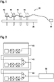
- Fig. 1 shows a schematic view of a first embodiment of an elevator car load measurement system 10 according to the present invention.
- Fig. 2 shows a schematic view of a daisy chain of the force sensors 40, 42, 44, 46.
- the elevator system comprises an elevator car which is held movably by one or more suspension traction means.
- force sensors 40, 42, 44, 46 are installed at the fix point 30 of the suspension traction means of the elevator car 12.
- the force sensor 40, 42, 44, 46 measure the force exerted on the suspension traction means, respectively.
- Fig. 1 four force sensors 40, 42, 44, 46 are installed.
- Each force sensors 40, 42, 44, 46 measure the force exerted on one of the suspension traction means.
- the force sensors 40, 42, 44, 46 are daisy chained, i.e., are connected in series. This means that each force sensor 40, 42, 44, 46 is connected with another force such that all force sensors 40, 42, 44, 46 are connected along a chain.
- the signal of one force sensors 40, 42, 44 is sent to the next force sensor 42, 44, 46 in the daisy chain until the last force sensor 46 in the daisy chain sends the signal to the controller 58.
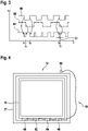
- the force sensor 40, 42, 44, 46 converts the measured force into a frequency. This conversion can be done in several steps as shown in Fig. 2 . First, the measured force is converted into a voltage (e.g., via a Wheatstone bridge) which is proportional to the measured force. Then, the voltage is converted into a frequency. The wavelength of the frequency generated by the respective force sensor 40, 42, 44, 46 is proportional to the force measured by the respective force sensor 40, 42, 44, 46.
- the frequency signals are rectangular waveform signals, respectively.
- the first force sensor 40 is connected with a second force sensor 42.
- the second force sensor 42 is connected with a third force sensor 44.
- the third force sensor 44 is connected to a fourth force sensor 46.
- the fourth force sensor 46 is connected to a controller 58.
- the first frequency signal 80 with a first frequency is forwarded/sent to the second force sensor 42.
- the second force sensors 42 measures the force exerted on the second force sensor 42.
- the measured force is converted to a second frequency signal 82, wherein the frequency of the second frequency signal 82 is proportional to the measured force.
- the first frequency signal 80 is added to the second frequency signal 82 by the second force sensor 42.
- the addition is carried out as follows: if at least one of the first frequency signal 80 and the second frequency signal 82 has a waveform edge, a waveform edge is generated in the frequency sum signal 84. I.e., if either one of the first frequency signal 80 and the second frequency signal 82 has a waveform edge at a point of time, the frequency sum signal 84 also has waveform edge at that point of time.
- changes (waveform edges) in the square-wave form of the first frequency signal 80 and/or the second frequency signal 82 can be represented by a change of the frequency sum signal 84 (waveform edge).
- the frequencies of the two square-wave form frequency signals are added which is indicated by the "Hz + Hz" in Fig. 2 , i.e., the number of waveform edges in the frequency sum signal 84 per time unit equals the number of waveform edges in the first frequency signal 80 per time unit plus the number of waveform edges in the second frequency signal 82 per time unit.
- the devices denoted with "Hz+Hz" in Fig. 2 can comprise one or several simple logic devices and/or can comprise one or several CPUs and/or ASICs.
- the CPU or ASIC can carry out a complex (logic) function.
- the simple logic device, the CPU and/or ASIC can be adapted such or programmed such that the adding of the frequency signals is carried out as described in the following in connection with Fig. 3 .
- Fig. 3 shows a schematic diagram of the first frequency signal 80, the second frequency signal 82 and the frequency sum signal 84.
- the frequency signals 80, 82, 84 (first frequency signal 80, the second frequency signal 82 and frequency sum signal 84) are drawn shifted along the y-axis in Fig. 3 .
- This shift of the different frequency signals 80, 82, 84 along the y-axis of Fig. 3 is for illustration purposes only, i.e., to show all frequency signals 80, 82, 84 in a single diagram.
- a waveform edge is generated in the frequency sum signal 84.
- a waveform edge is a change of the amplitude from 0 (minimum amplitude) to 1 (maximum amplitude) as well as a change of the amplitude from 1 (maximum amplitude) to 0 (minimum amplitude).
- the first frequency signal 80 has a waveform edge.
- a waveform edge in the frequency sum signal 84 at the point of time t 1 is generated.
- the second frequency signal 82 has a waveform edge.
- a waveform edge in the frequency sum signal 84 at the point of time t 2 is generated.
- the first frequency signal 80 has a waveform edge.
- a waveform edge in the frequency sum signal 84 at point of time t 3 is generated. And so on.
- the frequency sum signal 84 is forwarded/sent from the second force sensor 42 to the third force sensor 44.
- the third force sensors 44 measures the force exerted on the third force sensor 44.
- the measured force is converted to a third frequency signal, wherein the frequency of the third frequency signal is proportional to the measured force.
- the frequency sum signal 84 received from the second force sensor 42 is added to the third frequency signal.
- the addition of the frequency sum signal 84 to the third frequency is done according to the addition of the first frequency signal 80 to the second frequency signal 82. I.e., each time the received frequency sum signal 84 and/or the third frequency signal has a waveform edge, a waveform edge is generated in the frequency sum signal 84 to be outputted by the third force sensor 44. The newly generated frequency sum signal 84 of the third force sensor 44 is sent to the fourth force sensor 46.
- the fourth force sensor 46 measures the force exerted on the fourth force sensor 46.
- the measured force is converted to a fourth frequency signal, wherein the frequency of the fourth frequency signal is proportional to the measured force.
- the frequency sum signal 84 received from the third force sensor 44 is added to the fourth frequency signal. forwarded/sent to the controller 58.
- the addition of the frequency sum signal 84 to the fourth frequency is done according to the addition of the first frequency signal 80 to the second frequency signal 82. I.e., each time the received frequency sum signal 84 and/or the fourth frequency signal has a waveform edge, a waveform edge is generated in the frequency sum signal 84 to be outputted by the fourth force sensor 46.
- the newly generated frequency sum signal 84 of the fourth force sensor 46 is sent to the controller 58.
- more than four (e.g., five, six or more than five) force sensors 40, 42, 44, 46 can be daisy chained this way.
- the last force sensor 46 in the daisy chain can have a CAN interface.
- the frequency sum signal 84 can be sent to the controller 58 and via the CAN interface to other devices.
- the controller 58 can be part of a central control unit of the elevator/elevator system.
- Each force sensor 40, 42, 44, 46 can have a strain gauge.
- Each force sensor 40, 42, 44, 46 of the daisy chain has the same sensitivity, e.g., 1.25 Hz/N. It can have an offset when no force is applied, e.g. 8k Hz for a force of zero Newton.
- the waveform edge is a change from 0 to 1 or from 1 to 0, i.e., a rising or falling edge.
- one of the force sensor 40, 42, 44, 46 If one of the force sensor 40, 42, 44, 46 has a problem/malfunction, it generates a frequency signal with a set error frequency.
- the set error frequency corresponds to a frequency normally not generated, i.e., a frequency which does not correspond to a normally measured force.
- the set error frequency can be a very high frequency or a very low frequency (e.g., 4 kHz or 0 Hz).
- the respective force sensor 40, 42, 44, 46 receives a frequency signal with the set error frequency from the previous force sensor 40, 42, 44, 46 along the daisy chain, the received frequency signal is not added to the frequency signal generated in this force sensor 40, 42, 44, 46, but the force sensor 40, 42, 44, 46 generates a frequency sum signal 84 with the set error frequency. This way, if one force sensor 40, 42, 44, 46 generates a frequency signal with the set error frequency, this signal is forwarded unchanged along the daisy chain and finally received by the controller 58. If the controller 58 receives a signal with the set error frequency, a warning signal is generated and/or the operation of the elevator car 12 is stopped.
- the controller 58 receives a frequency sum signal 84 which contains information from all force sensors 40, 42, 44, 46. I.e., the frequency sum signal 84 comprises all information about the load of the elevator car 12.
- the frequency sum signal 84 is sent from the last force sensor 46 in the daisy chain to the controller 58.
- the controller 58 analyzes the frequency sum signal 84 by determining the number of waveform edges in a set time period (e.g., 1 second). The number of waveform wedges in this set time period is proportional to the sum of the forces measured by the force sensors 40, 42, 44, 46.
- the sensitivity of the force sensors 40, 42, 44, 46, i.e., which frequency corresponds to which measured force is known. Since, the weight of the empty elevator car 12 is known, the load of the elevator car 12 can be determined.
- the forces exerted on the suspension traction means can change over time, but the overall sum remains the same if the load of the elevator car 12 stays the same.
- two frequency signals are received by a pair of force sensors (which generate two frequency signals) and the four frequency signals (two frequency signals from one or two force sensors before in the daisy chain and the two frequency signals of the two force sensors at this point in the chain) are added together in one step.
- All waveform edges in either the received first frequency signal 80 or in the second frequency signal 82 are passed on/transferred to the frequency sum signal 84 which is sent to the next force sensor 42, 44, 46 along the daisy chain or the controller 58 (if the respective force sensor 40, 42, 44, 46 is the last force sensor in the daisy chain).
- the delay time ⁇ t is chosen/set such that the minimal duty cycle of the maximum expected frequency is guaranteed.
- the frequency sum signal 84 which is sent by one force sensor 40, 42, 44 in the daisy chain to the next force sensor 42, 44, 46 can be the so-called first frequency signal 80.
- This so-called first frequency signal 80 is then added to the second frequency signal 82, wherein the so-called second frequency signal 82 is the frequency signal generated in that respective force sensor 40, 42, 44, 46 (based on the measured force).
- Fig. 4 shows a schematic view of a second embodiment of an elevator car load measurement system 10 according to the present invention.
- the elevator car 12 comprises a car enclosure module 15 which is disposed within a car traction module 17.
- the car enclosure module 15 is held floatingly within the car traction module 17. This means, that the car enclosure module 15 can move relative to the car traction module 17.
- the car traction module 17 is connected to the suspension traction means.
- the cabin to transport persons and/or goods is located inside the car enclosure module 15.
- the force sensors 40, 42, 44, 46 are disposed between the car enclosure module 15 and the car traction module 17 of the elevator car 12.
- the force sensors 40, 42, 44, 46 are disposed below the car enclosure module 15 along the direction of gravity (the direction of gravity runs in Fig. 4 from top to bottom).
- the force sensors 40, 42, 44, 46 are daisy chained and connected to a controller 58 which is located at the car traction module 17. The controller 58 determines based on the frequency sum signal 84 the load of the elevator car 12.
- the forces measured at the respective force sensors 40, 42, 44, 46 can change over time. E.g., when a person moves from one side of the car enclosure model to the other side. However, the sum of the forces exerted on the force sensors 40, 42, 44, 46 stays the same, as long as the load of the elevator car 12 stays the same.
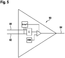
- Fig. 5 shows an error detection mechanism device 90.
- the error detection mechanism device 90 can be part of one or several force sensors 40, 42, 44, 46.
- the summation/outputting of the frequency sum signal of the force sensor 40, 42, 44, 46 can be monitored with the error detection mechanism 90: if the frequency of the first frequency signal 80 (which is received from the previous force sensor 40, 42, 44, 46 in the daisy chain) is out of range, or has a specific error frequency ERR (e.g., 0 Hz for no signal/force sensor 40, 42, 44, 46 broken or 4 kHz for overload of the force sensor 40, 42, 44, 46) then a frequency sum signal 84 with a frequency corresponding to the error frequency ERR is generated and forwarded to the next force sensor 40, 42, 44, 46 in the daisy chain or to the controller 58. If the frequency of the first frequency signal 80 neither is out of range nor has a specific error frequency ERR, the frequency sum signal is generated by adding the first frequency signal 80 to the second frequency signal
Description
- The present invention pertains to an elevator car load measurement system and a method for determining a load of an elevator car.
- Usually, the load measurement system for measuring/determining the load an elevator car in an elevator system, i.e., the additional weight which is in the elevator car, uses multiple sensors (for example force sensors). The disadvantage of this is that the installation of the multiple sensors, in particular the electric wiring of the multiple sensors, is complex and very costly. Typically, each sensor needs a separate signal line for transmitting the signal to a central controller. This increases the complexity and the costs of installation. Also, a multiplexer box is usually needed to collect the signals from all sensors and to transmit the information to a controller which determines the car load and/or controls the load management of the elevator car. This increases the costs for the elevator car load measurement system further.
-
DE 30 42 968 A1DE 30 42 968 A1 discloses the preamble of claim 1. - There may be a need for an elevator car load measurement system which can be installed technically easily and which has low production costs. There may be also a need for a method for determining a load of an elevator car which can be carried out with a measurement system which can be installed easily and which has low production costs. Such needs may be met with the subject-matters of the independent claims. Advantageous embodiments are defined in the dependent claims and in the following specification. According to a first aspect of the present invention, an elevator car load measurement system for determining a load of an elevator car according to claim 1 is provided.
- By this, generally, less signal lines and/or less material to transport the frequency signals from the force sensors to the controller are needed. Typically, not every force sensor needs a separate signal line which directly connects the respective force sensor to the controller. In general, only the force sensor at the end of the daisy chain needs a signal line which is directly connected to the controller. Thus, typically, material, installation time and costs are saved. In particular, usually, no multiplexer box for collecting the signals from the sensors is needed. In general, the daisy chain can comprise more than two force sensors, e.g., three or four force sensor. Typically, in each of the force sensors of the daisy chain, the frequency signal of the previous force sensors can be added to the frequency signal of the present force sensor. Usually, the frequency sum signal of the last force sensor in the daisy chain is forwarded to the controller, wherein the frequency sum signal is produced by adding one frequency signal after the other in the force sensors of the daisy chain. In addition, typically, the distances between the force sensors can be very large, since a frequency signal, in particular a square-form wave signal, can be transported without loss of information over long distances. In general, from the frequency sum signal received at the controller, the total weight (i.e., the sum of the forces measured) of the elevator car can be calculated based on the number of waveform edges in a set time period (e.g., one second).
- According to a second aspect of the present invention, a method for determining a load of an elevator car via a plurality of force sensors which are daisy-chained according to claim 6 is provided.
- Generally, with this method less signal lines and/or less material to transport the frequency signals from the force sensors to the controller are needed. Typically, with this method not every force sensor needs a separate signal line which directly connects the respective force sensor to the controller. In general, only the force sensor at the end of the daisy chain needs a signal line which is directly connected to the controller. Thus, typically, this method saves material, installation time and costs. In particular, usually, no multiplexer box for collecting the signals from the sensors is needed. In general, the daisy chain can comprise more than two force sensors, e.g., three or four force sensor. Typically, in each of the force sensors of the daisy chain, the frequency signal of the previous force sensors can be added to the frequency signal of the present force sensor. Usually, the frequency sum signal of the last force sensor in the daisy chain is sent/forwarded to the controller, wherein the frequency sum signal is produced by adding one frequency signal after the other in the force sensors of the daisy chain. In addition, typically, the signals of the force sensors can be sent over large distances between the force sensors, since a frequency signal, in particular a square-form wave signal, can be transported without loss of information over long distances. In general, the controller can calculate from the frequency sum signal received at the controller the total weight (i.e., the sum of the forces measured) of the elevator car based on the number of waveform edges in a set time period.
- The adding of the frequency signals in the elevator car load measurement system and/or in the method for determining a load of an elevator car is usually not an AND-association (a logic "AND" -gate).
- According to the present invention, the adding of the frequency signals in the elevator car load measurement system and/or in the method for determining a load of an elevator car can be carried out as follows: if at least one of the first frequency signal and the second frequency signal has a waveform edge, a waveform edge is generated in the frequency sum signal. I.e., if either one of the first frequency signal and the second frequency signal has a waveform edge at a point of time, the frequency sum signal also has waveform edge at that point of time. Thus, changes (waveform edges) in the square-wave form of the first frequency signal and/or the second frequency signal can be represented by a change of the frequency sum signal (waveform edge). This kind of adding is one possibility for generating and outputting a frequency sum signal based on a first frequency signal and a second frequency signal.
- The adding of the first frequency signal and the second frequency signal can be carried out by a simple electronic circuit or by a CPU or an ASIC with a multitude of basic electronic elements. The CPU or ASIC can carry out a complex (logic) function. In particular, the CPU or the ASIC can be programmed such that the adding of the frequency signal is carried out such that if at least one of the first frequency signal and the second frequency signal has a waveform edge at a point of time, a waveform edge is generated in the frequency sum signal at that point of time. Ideas underlying embodiments of the present invention may be interpreted as being based, inter alia, on the following observations and recognitions.
- According to a preferred embodiment, the force sensors are adapted such that if the first frequency signal and the second frequency signal have a waveform edge at the same point of time which is a first point of time, one waveform edge in the frequency sum signal is generated at the first point of time and one further waveform edge in the frequency sum signal is generated at a second point of time which lies a delay time after the first point of time, in particular a set delay time after the first point of time. One advantage hereof is that, typically, no information is lost when adding the first frequency signal to the second frequency signal, even if both frequency signals have coincidentally a waveform edge at the same point of time. In general, this increases the reliability of the elevator car load measurement system. This is a further possibility of adding the first frequency signal and the second frequency signal to generate and output the frequency sum signal.
- According to a preferred embodiment, the force sensors are adapted such that, if the respective force sensor detects a malfunction, the respective force sensor generates a second frequency signal with a set error frequency, wherein the force sensors are further adapted such that, if the first frequency signal has a frequency which corresponds to the set error frequency, a frequency sum signal with the set error frequency is generated and forwarded. One advantage hereof is that an error/malfunction of one of the force sensors can be transported via the daisy chain, generally. Typically, as soon as at least one force sensors detects an error/malfunction, the controller will receive this information via the daisy chain and can take corresponding measures. Usually, for example, the controller can generate a warning signal and/or stop the operation of the elevator. Generally, one advantage hereof is that, if a force sensor sends an error signal, i.e., an error frequency, the error frequency is forwarded to the controller by the other force sensors without modification. Thus, typically, the information that at least one of the force sensors detected a problem/malfunction is forwarded to the controller reliably. This is a further possibility of adding the first frequency signal and the second frequency signal to generate and output the frequency sum signal.
- According to a preferred embodiment, the force sensors are disposed between a car enclosure module and a car traction module of the elevator car, wherein the car enclosure module is held floatingly within the car traction module, wherein the force sensors measure the force exerted by the car enclosure module on the car traction module, respectively. Typically, by this, the load of the elevator car can be determined more precisely.
- According to a preferred embodiment, the force sensors are disposed at fix points of suspension traction means for holding and moving the elevator car, wherein the measured forces are forces exerted by the suspension traction means on the force sensors, respectively. In general, by this, the load of the elevator car can be determined technically easily. Furthermore, typically, the force sensors can also be used for monitoring the status of the suspension traction means for increasing the safety of the operation of the elevator car.
- According to a preferred embodiment of the method, if the first frequency signal and the second frequency signal have a waveform edge at the same point of time which is a first point of time, one waveform edge in the frequency sum signal is generated at the first point of time and one further waveform edge in the frequency sum signal is generated at a second point of time which lies a delay time after the first point of time, in particular a set delay time after the first point of time. Typically, one advantage hereof is that no information is lost when adding the first frequency signal to the second frequency signal, even if both frequency signals have coincidentally a waveform edge at the same point of time. Usually, the reliability of the method is increased this way. This is a further possibility of adding the first frequency signal and the second frequency signal to generate and output the frequency sum signal.
- According to a preferred embodiment of this method, if the respective force sensors detects a malfunction, a second frequency signal with a set error frequency is generated by the respective force sensor, and wherein, if the first frequency signal has a frequency which corresponds to the set error frequency, a frequency sum signal with the set error frequency is generated and forwarded. Typically, by this, an error/malfunction of one of the force sensors can be transported via the daisy chain. Generally, as soon as at least one force sensors detects an error/malfunction, the controller will receive this information via the daisy chain and can take corresponding measures. Typically, the controller can generate a warning signal and/or stop the operation of the elevator as corresponding measures. Furthermore, generally, one advantage hereof is that, if a force sensor sends an error signal, i.e., an error frequency, the error frequency is forwarded to the controller by the other force sensors without modification. Thus, usually, the information that at least one of the force sensors detected a problem/malfunction is forwarded to the controller reliably. This is a further possibility of adding the first frequency signal and the second frequency signal to generate and output the frequency sum signal.
- According to a preferred embodiment of the method, the measured forces are forces exerted by a car enclosure module on a car traction module of the elevator car, respectively, wherein the car enclosure module is held floatingly within the car traction module. Usually, one advantage hereof is that the load of the elevator car is determined more precisely.
- According to a preferred embodiment of the method, the measured forces are forces exerted by suspension traction means on the force sensors at fix points of the suspension traction means, respectively, wherein the suspension traction means hold and move the elevator car. Typically, one advantage hereof is that the load of the elevator car is determined technically easily. Also, generally, the force sensors which generate the frequency signals to determine the car load can also be used for monitoring the status of the suspension traction means for increasing the safety of the operation of the elevator car.
- Usually, the suspension traction means can comprise a rope and/or a belt, respectively. Typically, the plurality of force sensors can comprise two force sensors, three force sensors, four force sensors, five force sensors or more than five force sensors (e.g., six, seven or eight force sensors).
- In the following, advantageous embodiments of the invention will be described with reference to the enclosed drawing. However, neither the drawing nor the description shall be interpreted as limiting the invention.
- Fig. 1 shows
- a schematic view of a first embodiment of an elevator car load measurement system according to the present invention;
- Fig. 2 shows
- a schematic view of a daisy chain of the force sensors;
- Fig. 3 shows
- a schematic diagram of the first frequency signal, the second frequency signal and the frequency sum signal;
- Fig. 4 shows
- a schematic view of a second embodiment of an elevator car load measurement system according to the present invention; and
- Fig. 5 shows
- an error detection mechanism device.
- The figures are only schematic and not to scale. Same reference signs refer to same or similar features.
-
Fig. 1 shows a schematic view of a first embodiment of an elevator carload measurement system 10 according to the present invention.Fig. 2 shows a schematic view of a daisy chain of theforce sensors - The elevator system comprises an elevator car which is held movably by one or more suspension traction means. At the
fix point 30 of the suspension traction means of theelevator car 12,force sensors force sensor Fig. 1 , fourforce sensors force sensors elevator car 12. - The
force sensors force sensor force sensors force sensors next force sensor last force sensor 46 in the daisy chain sends the signal to thecontroller 58. - The
force sensor Fig. 2 . First, the measured force is converted into a voltage (e.g., via a Wheatstone bridge) which is proportional to the measured force. Then, the voltage is converted into a frequency. The wavelength of the frequency generated by therespective force sensor respective force sensor - The frequency signals are rectangular waveform signals, respectively.
- The
first force sensor 40 is connected with asecond force sensor 42. Thesecond force sensor 42 is connected with athird force sensor 44. Thethird force sensor 44 is connected to afourth force sensor 46. Thefourth force sensor 46 is connected to acontroller 58. - The
first frequency signal 80 with a first frequency is forwarded/sent to thesecond force sensor 42. Thesecond force sensors 42 measures the force exerted on thesecond force sensor 42. The measured force is converted to asecond frequency signal 82, wherein the frequency of thesecond frequency signal 82 is proportional to the measured force. Thefirst frequency signal 80 is added to thesecond frequency signal 82 by thesecond force sensor 42. - The "+"-signs in
Fig. 2 indicate that the frequency signals 80, 82, 84 are added as shown in Fig. - 3. According to the invention, the addition is carried out as follows: if at least one of the
first frequency signal 80 and thesecond frequency signal 82 has a waveform edge, a waveform edge is generated in thefrequency sum signal 84. I.e., if either one of thefirst frequency signal 80 and thesecond frequency signal 82 has a waveform edge at a point of time, thefrequency sum signal 84 also has waveform edge at that point of time. Thus, changes (waveform edges) in the square-wave form of thefirst frequency signal 80 and/or thesecond frequency signal 82 can be represented by a change of the frequency sum signal 84 (waveform edge). This way, the frequencies of the two square-wave form frequency signals are added which is indicated by the "Hz + Hz" inFig. 2 , i.e., the number of waveform edges in thefrequency sum signal 84 per time unit equals the number of waveform edges in thefirst frequency signal 80 per time unit plus the number of waveform edges in thesecond frequency signal 82 per time unit. - The devices denoted with "Hz+Hz" in
Fig. 2 can comprise one or several simple logic devices and/or can comprise one or several CPUs and/or ASICs. The CPU or ASIC can carry out a complex (logic) function. In particular, the simple logic device, the CPU and/or ASIC can be adapted such or programmed such that the adding of the frequency signals is carried out as described in the following in connection withFig. 3 . - The addition of the
first frequency signal 80 and thesecond frequency signal 82 is shown inFig. 3. Fig. 3 shows a schematic diagram of thefirst frequency signal 80, thesecond frequency signal 82 and thefrequency sum signal 84. - The frequency signals 80, 82, 84 (
first frequency signal 80, thesecond frequency signal 82 and frequency sum signal 84) are drawn shifted along the y-axis inFig. 3 . This shift of the different frequency signals 80, 82, 84 along the y-axis ofFig. 3 is for illustration purposes only, i.e., to show all frequency signals 80, 82, 84 in a single diagram. Usually, in reality, there is no shift of the amplitudes between the frequency signals 80, 82, 84, but the maximum amplitudes and the minimum amplitudes of all frequency signals 80, 82, 84 are the same. - At the points of time where either one of the
first frequency signal 80 and thesecond frequency signal 82 or both has/have a waveform edge, a waveform edge is generated in thefrequency sum signal 84. In particular, a waveform edge is a change of the amplitude from 0 (minimum amplitude) to 1 (maximum amplitude) as well as a change of the amplitude from 1 (maximum amplitude) to 0 (minimum amplitude). - E.g., at point of time t1, the
first frequency signal 80 has a waveform edge. Thus, a waveform edge in thefrequency sum signal 84 at the point of time t1 is generated. At the point of time t2, thesecond frequency signal 82 has a waveform edge. Thus, a waveform edge in thefrequency sum signal 84 at the point of time t2 is generated. At point of time t3, thefirst frequency signal 80 has a waveform edge. Thus, a waveform edge in thefrequency sum signal 84 at point of time t3 is generated. And so on. - If there is a waveform edge at the same point of time in both the
first frequency signal 80 and thesecond frequency signal 82, e.g., at point of time t4, then a waveform edge in thefrequency sum signal 84 at the point of time t4 is generated and a further waveform edge in thefrequency sum signal 84 is generated at the point of time t4+δt=t5 is generated. I.e., the further waveform edge is delayed by a preset delay time δt. Thus, no information is lost. Also, the minimum duty cycle of the maximum expected frequency is guaranteed this way. - The
frequency sum signal 84 is forwarded/sent from thesecond force sensor 42 to thethird force sensor 44. Thethird force sensors 44 measures the force exerted on thethird force sensor 44. The measured force is converted to a third frequency signal, wherein the frequency of the third frequency signal is proportional to the measured force. Thefrequency sum signal 84 received from thesecond force sensor 42 is added to the third frequency signal. - The addition of the
frequency sum signal 84 to the third frequency is done according to the addition of thefirst frequency signal 80 to thesecond frequency signal 82. I.e., each time the receivedfrequency sum signal 84 and/or the third frequency signal has a waveform edge, a waveform edge is generated in thefrequency sum signal 84 to be outputted by thethird force sensor 44. The newly generatedfrequency sum signal 84 of thethird force sensor 44 is sent to thefourth force sensor 46. - The
fourth force sensor 46 measures the force exerted on thefourth force sensor 46. The measured force is converted to a fourth frequency signal, wherein the frequency of the fourth frequency signal is proportional to the measured force. Thefrequency sum signal 84 received from thethird force sensor 44 is added to the fourth frequency signal. forwarded/sent to thecontroller 58. The addition of thefrequency sum signal 84 to the fourth frequency is done according to the addition of thefirst frequency signal 80 to thesecond frequency signal 82. I.e., each time the receivedfrequency sum signal 84 and/or the fourth frequency signal has a waveform edge, a waveform edge is generated in thefrequency sum signal 84 to be outputted by thefourth force sensor 46. The newly generatedfrequency sum signal 84 of thefourth force sensor 46 is sent to thecontroller 58. - This way, no delay in the propagation of the signals across the daisy chain is present. As soon as a waveform edge is detected in one of the frequency signals to be added, a waveform edge is generated in the
frequency sum signal 84 which is output by theforce sensor force sensor - Also, more than four (e.g., five, six or more than five)
force sensors - The
last force sensor 46 in the daisy chain can have a CAN interface. Thefrequency sum signal 84 can be sent to thecontroller 58 and via the CAN interface to other devices. - The
controller 58 can be part of a central control unit of the elevator/elevator system. - Each
force sensor force sensor - The waveform edge is a change from 0 to 1 or from 1 to 0, i.e., a rising or falling edge.
- If one of the
force sensor - If the
respective force sensor previous force sensor force sensor force sensor frequency sum signal 84 with the set error frequency. This way, if oneforce sensor controller 58. If thecontroller 58 receives a signal with the set error frequency, a warning signal is generated and/or the operation of theelevator car 12 is stopped. - The
controller 58 receives afrequency sum signal 84 which contains information from allforce sensors frequency sum signal 84 comprises all information about the load of theelevator car 12. Thefrequency sum signal 84 is sent from thelast force sensor 46 in the daisy chain to thecontroller 58. Thecontroller 58 analyzes thefrequency sum signal 84 by determining the number of waveform edges in a set time period (e.g., 1 second). The number of waveform wedges in this set time period is proportional to the sum of the forces measured by theforce sensors force sensors empty elevator car 12 is known, the load of theelevator car 12 can be determined. - The forces exerted on the suspension traction means can change over time, but the overall sum remains the same if the load of the
elevator car 12 stays the same. - It is also possible that two frequency signals are received by a pair of force sensors (which generate two frequency signals) and the four frequency signals (two frequency signals from one or two force sensors before in the daisy chain and the two frequency signals of the two force sensors at this point in the chain) are added together in one step. The adding of the four frequency signals would be similar to the adding of two frequency signals. If one or more of the four frequency signals has a waveform edge (i.e., a step from 0 to 1 or from 1 to 0) at a point of time (e.g., t=t6), a waveform edge is generated in the
frequency sum signal 84 at this point in time (t=t6). - If two frequency signals have a waveform edge at the same point in time, one waveform edge in the
frequency sum signal 84 is generated at this point in time (t=t6) and a further/second waveform edge in thefrequency sum signal 84 is generated a set delay time δt later (t=t6+δt). The same applies correspondingly, if three frequency signals have a waveform edge at the same point in time. A first waveform edge in thefrequency sum signal 84 is generated at that point of time (e.g., t=t7), a second waveform edge in thefrequency sum signal 84 is generated a set delay time δt later (t=t7+δt) and a third waveform edge is generated two delay times δt later than the first waveform edge (t=t7+δt+δt). The same is applied correspondingly, if all four frequency signals have a waveform edge at the same point of time. - All waveform edges in either the received
first frequency signal 80 or in the second frequency signal 82 (generated by therespective force sensors frequency sum signal 84 which is sent to thenext force sensor respective force sensor - The delay time δt is chosen/set such that the minimal duty cycle of the maximum expected frequency is guaranteed.
- The
frequency sum signal 84 which is sent by oneforce sensor next force sensor first frequency signal 80. This so-calledfirst frequency signal 80 is then added to thesecond frequency signal 82, wherein the so-calledsecond frequency signal 82 is the frequency signal generated in thatrespective force sensor -
Fig. 4 shows a schematic view of a second embodiment of an elevator carload measurement system 10 according to the present invention. In this embodiment, theelevator car 12 comprises acar enclosure module 15 which is disposed within acar traction module 17. Thecar enclosure module 15 is held floatingly within thecar traction module 17. This means, that thecar enclosure module 15 can move relative to thecar traction module 17. Thecar traction module 17 is connected to the suspension traction means. The cabin to transport persons and/or goods is located inside thecar enclosure module 15. - In this embodiment, the
force sensors car enclosure module 15 and thecar traction module 17 of theelevator car 12. In particular, theforce sensors car enclosure module 15 along the direction of gravity (the direction of gravity runs inFig. 4 from top to bottom). Theforce sensors controller 58 which is located at thecar traction module 17. Thecontroller 58 determines based on thefrequency sum signal 84 the load of theelevator car 12. - The forces measured at the
respective force sensors force sensors elevator car 12 stays the same. -
Fig. 5 shows an errordetection mechanism device 90. The errordetection mechanism device 90 can be part of one orseveral force sensors force sensor previous force sensor force sensor force sensor frequency sum signal 84 with a frequency corresponding to the error frequency ERR is generated and forwarded to thenext force sensor controller 58. If the frequency of thefirst frequency signal 80 neither is out of range nor has a specific error frequency ERR, the frequency sum signal is generated by adding thefirst frequency signal 80 to thesecond frequency signal 82 as described above. - Finally, it should be noted that the term "comprising" does not exclude other elements or steps and the "a" or "an" does not exclude a plurality. Also, elements described in association with different embodiments may be combined within the scope of the appended claims. It should also be noted that reference signs in the claims should not be construed as limiting the scope of the claims.
-
- 10
- elevator car load measurement system
- 12
- elevator car
- 15
- car enclosure module
- 17
- car traction module
- 30
- fix point
- 40
- first force sensor
- 42
- second force sensor
- 44
- third force sensor
- 46
- fourth force sensor
- 58
- controller
- 80
- first frequency signal
- 82
- second frequency signal
- 84
- frequency sum signal
- 90
- error detection mechanism device
- t1, t2, t3, t4, t5
- points of time
- δt
- delay time
Claims (10)
- Elevator car load measurement system (10) for determining a load of an elevator car (12),
wherein the elevator car load measurement system (10) comprises:a plurality of at least two force sensors (40, 42, 44, 46) which are daisy-chained, anda controller (58) for determining the load of the elevator car (12), the elevator car load measurement system being characterized in thateach force sensor (40, 42, 44, 46) is adapted for measuring a force exerted by the elevator car (12) on the respective force sensor (40, 42, 44, 46) and for generating a frequency signal with a square-wave form, wherein the frequency signal is proportional to the respective measured force,at least one first force sensor (40, 42, 44, 46) of the plurality of force sensors is adapted such that a first frequency signal (80) received from the previous force sensor (40, 42, 44, 46) along the daisy chain is added to a second frequency signal (82) generated by the first force sensor (40, 42, 44, 46) for generating an outputting a frequency sum signal (84), wherein the first frequency signal (80) is added to the second frequency signal (82) by generating a waveform edge in the frequency sum signal (84) at a point of time if the first frequency signal (80) and/or the second frequency signal (82) has a waveform edge at the respective point of time; andat least one force sensor (40, 42, 44, 46) of the at least one first force sensor is adapted for forwarding the frequency sum signal (84) to the controller (58). - Elevator car load measurement system (10) according to claim 1, wherein
the force sensors (40, 42, 44, 46) are adapted such that if the first frequency signal (80) and the second frequency signal (82) have a waveform edge at the same point of time which is a first point of time, one waveform edge in the frequency sum signal (84) is generated at the first point of time and one further waveform edge in the frequency sum signal (84) is generated at a second point of time which lies a delay time (δt) after the first point of time, in particular a set delay time (δt) after the first point of time. - Elevator car load measurement system (10) according to one of the preceding claims, wherein the force sensors (40, 42, 44, 46) are adapted such that, if the respective force sensor (40, 42, 44, 46) detects a malfunction, the respective force sensor (40, 42, 44, 46) generates a second frequency signal (82) with a set error frequency,
wherein the force sensors (40, 42, 44, 46) are further adapted such that, if the first frequency signal (80) has a frequency which corresponds to the set error frequency, a frequency sum signal (84) with the set error frequency is generated and forwarded. - Elevator car load measurement system (10) according to one of the preceding claims, wherein the force sensors (40, 42, 44, 46) are disposed between a car enclosure module (15) and a car traction module (17) of the elevator car (12), wherein the car enclosure module (15) is held floatingly within the car traction module (17),
wherein the force sensors (40, 42, 44, 46) measure the force exerted by the car enclosure module (15) on the car traction module (17), respectively. - Elevator car load measurement system (10) according to one of claims 1-3, wherein
the force sensors (40, 42, 44, 46) are disposed at fix points (30) of suspension traction means for holding and moving the elevator car (12), wherein the measured forces are forces exerted by the suspension traction means on the force sensors (40, 42, 44, 46), respectively. - Method for determining a load of an elevator car (12) via a plurality of force sensors (40, 42, 44, 46) which are daisy-chained,
wherein the method comprises the following steps:- measuring forces exerted by the elevator car (12) on the force sensors (40, 42, 44, 46), respectively;- generating frequency signals with a square-wave form, respectively, wherein the frequency signal is proportional to the measured force, respectively;- receiving a first frequency signal (80) received from the previous force sensor (40, 42, 44, 46) along the daisy chain;- adding the first frequency signal (80) to a second frequency signal (82) of the respective force sensor (40, 42, 44, 46) for generating a frequency sum signal (84); wherein the first frequency signal (80) is added to the second frequency signal (82) by generating a waveform edge in the frequency sum signal (84) at a point of time if the first frequency signal (80) and/or the second frequency signal (82) has a waveform edge at the respective point of time;- forwarding the frequency sum signal (84) to the next force sensor (42, 44, 46) along the daisy chain or to a controller (58); and- determining the load of the elevator car (12) based on the frequency sum signal (84) in the controller (58). - Method according to claim 6, wherein
if the first frequency signal (80) and the second frequency signal (82) have a waveform edge at the same point of time which is a first point of time, one waveform edge in the frequency sum signal (84) is generated at the first point of time and one further waveform edge in the frequency sum signal (84) is generated at a second point of time which lies a delay time (δt) after the first point of time, in particular a set delay time (δt) after the first point of time. - Method according to one of the claims 6-7, wherein,
if the respective force sensors (40, 42, 44, 46) detects a malfunction, a second frequency signal (82) with a set error frequency is generated by the respective force sensor (40, 42, 44, 46), and wherein, if the first frequency signal (80) has a frequency which corresponds to the set error frequency, a frequency sum signal (84) with the set error frequency is generated and forwarded. - Method according to one of the claims 6-8, wherein
the measured forces are forces exerted by a car enclosure module (15) on a car traction module (17) of the elevator car (12), respectively, wherein the car enclosure module (15) is held floatingly within the car traction module (17). - Method according to one of the claims 6-8, wherein
the measured forces are forces exerted by suspension traction means on the force sensors (40, 42, 44, 46) at fix points (30) of the suspension traction means, respectively, wherein the suspension traction means hold and move the elevator car (12).
Applications Claiming Priority (2)
| Application Number | Priority Date | Filing Date | Title |
|---|---|---|---|
| EP17164301 | 2017-03-31 | ||
| PCT/EP2018/057663 WO2018178023A1 (en) | 2017-03-31 | 2018-03-26 | Elevator car load measurement system and method for determining a load of an elevator car |
Publications (2)
| Publication Number | Publication Date |
|---|---|
| EP3601131A1 EP3601131A1 (en) | 2020-02-05 |
| EP3601131B1 true EP3601131B1 (en) | 2022-05-11 |
Family
ID=58464426
Family Applications (1)
| Application Number | Title | Priority Date | Filing Date |
|---|---|---|---|
| EP18712908.5A Active EP3601131B1 (en) | 2017-03-31 | 2018-03-26 | Elevator car load measurement system and method for determining a load of an elevator car |
Country Status (4)
| Country | Link |
|---|---|
| US (1) | US11603285B2 (en) |
| EP (1) | EP3601131B1 (en) |
| CN (1) | CN110536853B (en) |
| WO (1) | WO2018178023A1 (en) |
Family Cites Families (23)
| Publication number | Priority date | Publication date | Assignee | Title |
|---|---|---|---|---|
| DE3042968A1 (en) * | 1980-11-14 | 1982-07-01 | M.A.N. Maschinenfabrik Augsburg-Nürnberg AG, 8500 Nürnberg | Load measurement and evaluation in lifts - by weighing cabin floor via measurement of displacement w.r.t frame |
| IT1190488B (en) * | 1986-02-10 | 1988-02-16 | D M G Spa | ELECTRONIC WEIGHT DETECTION DEVICE THROUGH SENSORS APPLIED UNDER THE WEIGHT SUPPORTING PLAN |
| US4939679A (en) * | 1988-08-09 | 1990-07-03 | Otis Elevator Company | Recalibrating an elevator load measuring system |
| US5004058A (en) * | 1990-03-27 | 1991-04-02 | Cardinal Scale Manufacturing Company | Weigh scale using multiple digital load cells |
| JPH0829894B2 (en) * | 1990-07-13 | 1996-03-27 | 三菱電機株式会社 | Elevator scale equipment |
| CN2105677U (en) | 1991-08-24 | 1992-05-27 | 福州市电子秤厂 | Portable electronic weigher on car |
| US5750945A (en) | 1996-06-03 | 1998-05-12 | Otis Elevator Company | Active elevator hitch |
| JPH10324473A (en) * | 1997-05-27 | 1998-12-08 | Mitsubishi Denki Bill Techno Service Kk | Abnormal vibration detecting device for elevator |
| US6639156B2 (en) * | 1999-12-30 | 2003-10-28 | Tom J. Luke | Method and device for monitoring inventory |
| HU226605B1 (en) * | 2000-05-01 | 2009-04-28 | Inventio Ag | Load-carrying means for cable-operated elevators with an integrated load measurement device |
| US6576849B2 (en) * | 2000-12-01 | 2003-06-10 | Mettler-Toledo, Inc. | Load cell diagnostics and failure prediction weighing apparatus and process |
| JP5225537B2 (en) * | 2001-02-09 | 2013-07-03 | 三菱電機株式会社 | Elevator load detection device |
| DE10221628B4 (en) * | 2002-05-15 | 2005-06-23 | Sartorius Ag | Force measuring system with several load cells and a circuit for calculating a total signal |
| JP2005003638A (en) | 2003-06-16 | 2005-01-06 | Fujikura Ltd | Obstacle detection device |
| JP4606236B2 (en) * | 2005-04-21 | 2011-01-05 | 大和製衡株式会社 | Weight measurement method |
| WO2008148590A1 (en) * | 2007-06-07 | 2008-12-11 | Mettler-Toledo Ag | Multiple-force-measuring device, force-measuring module, and method for status monitoring |
| CN201302478Y (en) | 2008-11-24 | 2009-09-02 | 李汶波 | Portable automobile weighting machine |
| CN102042864B (en) | 2009-10-23 | 2013-04-03 | 上海裕杰衡器有限公司 | Digital weighing sensor assembly and connecting method thereof |
| US8304670B2 (en) * | 2010-03-26 | 2012-11-06 | Ut-Battelle, Llc | Portable weighing system with alignment features |
| WO2012031961A1 (en) * | 2010-09-09 | 2012-03-15 | Inventio Ag | Load measuring device for an elevator installation |
| BR112014003862A2 (en) * | 2011-08-31 | 2017-03-14 | Hirschmann Automation & Control Gmbh | load receiver load measurement of lifting devices |
| EP2604563B1 (en) * | 2011-12-12 | 2015-10-21 | Cedes AG | Safety device, drive device and lift device |
| CN203889829U (en) * | 2014-06-05 | 2014-10-22 | 上海托菲机电科技有限公司 | Hall sensor for elevator load detection |
-
2018
- 2018-03-26 CN CN201880023376.0A patent/CN110536853B/en active Active
- 2018-03-26 US US16/493,784 patent/US11603285B2/en active Active
- 2018-03-26 WO PCT/EP2018/057663 patent/WO2018178023A1/en active Application Filing
- 2018-03-26 EP EP18712908.5A patent/EP3601131B1/en active Active
Also Published As
| Publication number | Publication date |
|---|---|
| US11603285B2 (en) | 2023-03-14 |
| US20200130989A1 (en) | 2020-04-30 |
| CN110536853A (en) | 2019-12-03 |
| WO2018178023A1 (en) | 2018-10-04 |
| CN110536853B (en) | 2022-04-05 |
| EP3601131A1 (en) | 2020-02-05 |
Similar Documents
| Publication | Publication Date | Title |
|---|---|---|
| US5233139A (en) | Measurement of traction, operation of brake, friction safety gear, and cable forces of an elevator | |
| CN104768862B (en) | The MONITOR AND CONTROL SYSTEM of lift facility | |
| EP3418234B1 (en) | Elevator termination assembly that provides an indication of elevator car load | |
| US8258415B2 (en) | Method of monitoring the free mobility of a force-measuring device and force-measuring module for applying method | |
| JP2009084009A (en) | Moving body speed detection device | |
| US9617116B2 (en) | Load measuring device for an elevator installation | |
| EP3708990B1 (en) | Fiber optic sensor unit, optical measuring system, axle-counting device, axle-counting method | |
| EP3601131B1 (en) | Elevator car load measurement system and method for determining a load of an elevator car | |
| EP3720743B1 (en) | A system for determining an angular speed of an axle of a railway vehicle and corresponding method | |
| CN109374160A (en) | A kind of rail stress sensor for the detection of rail truck Super leaning load | |
| NL9100591A (en) | Pressure sensitive mat counting feet to monitor passenger traffic - is placed in entry or exit path of vehicle, building etc. to detect and count persons passing through | |
| CN109186444A (en) | A kind of detection device and detection method of weighing scale platform limit distance | |
| CN209327003U (en) | Crane integrated performance detecting system | |
| KR101725282B1 (en) | system for collecting traffic information using load detecting device | |
| CN1264044A (en) | Device for testing position | |
| EP4286803A2 (en) | Intelligent digital load cell transducer | |
| KR101837732B1 (en) | load detecting device and load detecting system therewith | |
| KR20160092614A (en) | Multi-Channel Sensing Device And Control Method Thereof | |
| EP3428101A1 (en) | Elevator monitoring system for monitoring suspension traction means and method for monitoring suspension traction means | |
| CN107187983A (en) | A kind of elevator compensation chain chain breakage protection device | |
| CN110455393B (en) | High-accuracy real-time monitoring method for electronic belt scale | |
| CN207061550U (en) | Elevator compensation chain chain breakage protection device | |
| CN106744326B (en) | A kind of raising lift heavy weighs and control device | |
| KR102423583B1 (en) | System for monitoring break of mooring rope | |
| EP2569240B1 (en) | System for load detection in a cabin of an elevator |
Legal Events
| Date | Code | Title | Description |
|---|---|---|---|
| STAA | Information on the status of an ep patent application or granted ep patent |
Free format text: STATUS: UNKNOWN |
|
| STAA | Information on the status of an ep patent application or granted ep patent |
Free format text: STATUS: THE INTERNATIONAL PUBLICATION HAS BEEN MADE |
|
| PUAI | Public reference made under article 153(3) epc to a published international application that has entered the european phase |
Free format text: ORIGINAL CODE: 0009012 |
|
| STAA | Information on the status of an ep patent application or granted ep patent |
Free format text: STATUS: REQUEST FOR EXAMINATION WAS MADE |
|
| 17P | Request for examination filed |
Effective date: 20190814 |
|
| AK | Designated contracting states |
Kind code of ref document: A1 Designated state(s): AL AT BE BG CH CY CZ DE DK EE ES FI FR GB GR HR HU IE IS IT LI LT LU LV MC MK MT NL NO PL PT RO RS SE SI SK SM TR |
|
| AX | Request for extension of the european patent |
Extension state: BA ME |
|
| DAV | Request for validation of the european patent (deleted) | ||
| DAX | Request for extension of the european patent (deleted) | ||
| STAA | Information on the status of an ep patent application or granted ep patent |
Free format text: STATUS: EXAMINATION IS IN PROGRESS |
|
| 17Q | First examination report despatched |
Effective date: 20210602 |
|
| GRAP | Despatch of communication of intention to grant a patent |
Free format text: ORIGINAL CODE: EPIDOSNIGR1 |
|
| STAA | Information on the status of an ep patent application or granted ep patent |
Free format text: STATUS: GRANT OF PATENT IS INTENDED |
|
| INTG | Intention to grant announced |
Effective date: 20211109 |
|
| GRAS | Grant fee paid |
Free format text: ORIGINAL CODE: EPIDOSNIGR3 |
|
| GRAA | (expected) grant |
Free format text: ORIGINAL CODE: 0009210 |
|
| STAA | Information on the status of an ep patent application or granted ep patent |
Free format text: STATUS: THE PATENT HAS BEEN GRANTED |
|
| AK | Designated contracting states |
Kind code of ref document: B1 Designated state(s): AL AT BE BG CH CY CZ DE DK EE ES FI FR GB GR HR HU IE IS IT LI LT LU LV MC MK MT NL NO PL PT RO RS SE SI SK SM TR |
|
| REG | Reference to a national code |
Ref country code: GB Ref legal event code: FG4D |
|
| REG | Reference to a national code |
Ref country code: CH Ref legal event code: EP |
|
| REG | Reference to a national code |
Ref country code: AT Ref legal event code: REF Ref document number: 1491276 Country of ref document: AT Kind code of ref document: T Effective date: 20220515 |
|
| REG | Reference to a national code |
Ref country code: DE Ref legal event code: R096 Ref document number: 602018035388 Country of ref document: DE |
|
| REG | Reference to a national code |
Ref country code: IE Ref legal event code: FG4D |
|
| REG | Reference to a national code |
Ref country code: LT Ref legal event code: MG9D |
|
| RAP4 | Party data changed (patent owner data changed or rights of a patent transferred) |
Owner name: INVENTIO AG |
|
| REG | Reference to a national code |
Ref country code: NL Ref legal event code: MP Effective date: 20220511 |
|
| REG | Reference to a national code |
Ref country code: AT Ref legal event code: MK05 Ref document number: 1491276 Country of ref document: AT Kind code of ref document: T Effective date: 20220511 |
|
| PG25 | Lapsed in a contracting state [announced via postgrant information from national office to epo] |
Ref country code: SE Free format text: LAPSE BECAUSE OF FAILURE TO SUBMIT A TRANSLATION OF THE DESCRIPTION OR TO PAY THE FEE WITHIN THE PRESCRIBED TIME-LIMIT Effective date: 20220511 Ref country code: PT Free format text: LAPSE BECAUSE OF FAILURE TO SUBMIT A TRANSLATION OF THE DESCRIPTION OR TO PAY THE FEE WITHIN THE PRESCRIBED TIME-LIMIT Effective date: 20220912 Ref country code: NO Free format text: LAPSE BECAUSE OF FAILURE TO SUBMIT A TRANSLATION OF THE DESCRIPTION OR TO PAY THE FEE WITHIN THE PRESCRIBED TIME-LIMIT Effective date: 20220811 Ref country code: NL Free format text: LAPSE BECAUSE OF FAILURE TO SUBMIT A TRANSLATION OF THE DESCRIPTION OR TO PAY THE FEE WITHIN THE PRESCRIBED TIME-LIMIT Effective date: 20220511 Ref country code: LT Free format text: LAPSE BECAUSE OF FAILURE TO SUBMIT A TRANSLATION OF THE DESCRIPTION OR TO PAY THE FEE WITHIN THE PRESCRIBED TIME-LIMIT Effective date: 20220511 Ref country code: HR Free format text: LAPSE BECAUSE OF FAILURE TO SUBMIT A TRANSLATION OF THE DESCRIPTION OR TO PAY THE FEE WITHIN THE PRESCRIBED TIME-LIMIT Effective date: 20220511 Ref country code: GR Free format text: LAPSE BECAUSE OF FAILURE TO SUBMIT A TRANSLATION OF THE DESCRIPTION OR TO PAY THE FEE WITHIN THE PRESCRIBED TIME-LIMIT Effective date: 20220812 Ref country code: FI Free format text: LAPSE BECAUSE OF FAILURE TO SUBMIT A TRANSLATION OF THE DESCRIPTION OR TO PAY THE FEE WITHIN THE PRESCRIBED TIME-LIMIT Effective date: 20220511 Ref country code: ES Free format text: LAPSE BECAUSE OF FAILURE TO SUBMIT A TRANSLATION OF THE DESCRIPTION OR TO PAY THE FEE WITHIN THE PRESCRIBED TIME-LIMIT Effective date: 20220511 Ref country code: BG Free format text: LAPSE BECAUSE OF FAILURE TO SUBMIT A TRANSLATION OF THE DESCRIPTION OR TO PAY THE FEE WITHIN THE PRESCRIBED TIME-LIMIT Effective date: 20220811 Ref country code: AT Free format text: LAPSE BECAUSE OF FAILURE TO SUBMIT A TRANSLATION OF THE DESCRIPTION OR TO PAY THE FEE WITHIN THE PRESCRIBED TIME-LIMIT Effective date: 20220511 |
|
| PG25 | Lapsed in a contracting state [announced via postgrant information from national office to epo] |
Ref country code: RS Free format text: LAPSE BECAUSE OF FAILURE TO SUBMIT A TRANSLATION OF THE DESCRIPTION OR TO PAY THE FEE WITHIN THE PRESCRIBED TIME-LIMIT Effective date: 20220511 Ref country code: PL Free format text: LAPSE BECAUSE OF FAILURE TO SUBMIT A TRANSLATION OF THE DESCRIPTION OR TO PAY THE FEE WITHIN THE PRESCRIBED TIME-LIMIT Effective date: 20220511 Ref country code: LV Free format text: LAPSE BECAUSE OF FAILURE TO SUBMIT A TRANSLATION OF THE DESCRIPTION OR TO PAY THE FEE WITHIN THE PRESCRIBED TIME-LIMIT Effective date: 20220511 Ref country code: IS Free format text: LAPSE BECAUSE OF FAILURE TO SUBMIT A TRANSLATION OF THE DESCRIPTION OR TO PAY THE FEE WITHIN THE PRESCRIBED TIME-LIMIT Effective date: 20220911 |
|
| PG25 | Lapsed in a contracting state [announced via postgrant information from national office to epo] |
Ref country code: SM Free format text: LAPSE BECAUSE OF FAILURE TO SUBMIT A TRANSLATION OF THE DESCRIPTION OR TO PAY THE FEE WITHIN THE PRESCRIBED TIME-LIMIT Effective date: 20220511 Ref country code: SK Free format text: LAPSE BECAUSE OF FAILURE TO SUBMIT A TRANSLATION OF THE DESCRIPTION OR TO PAY THE FEE WITHIN THE PRESCRIBED TIME-LIMIT Effective date: 20220511 Ref country code: RO Free format text: LAPSE BECAUSE OF FAILURE TO SUBMIT A TRANSLATION OF THE DESCRIPTION OR TO PAY THE FEE WITHIN THE PRESCRIBED TIME-LIMIT Effective date: 20220511 Ref country code: EE Free format text: LAPSE BECAUSE OF FAILURE TO SUBMIT A TRANSLATION OF THE DESCRIPTION OR TO PAY THE FEE WITHIN THE PRESCRIBED TIME-LIMIT Effective date: 20220511 Ref country code: DK Free format text: LAPSE BECAUSE OF FAILURE TO SUBMIT A TRANSLATION OF THE DESCRIPTION OR TO PAY THE FEE WITHIN THE PRESCRIBED TIME-LIMIT Effective date: 20220511 Ref country code: CZ Free format text: LAPSE BECAUSE OF FAILURE TO SUBMIT A TRANSLATION OF THE DESCRIPTION OR TO PAY THE FEE WITHIN THE PRESCRIBED TIME-LIMIT Effective date: 20220511 |
|
| REG | Reference to a national code |
Ref country code: DE Ref legal event code: R097 Ref document number: 602018035388 Country of ref document: DE |
|
| PLBE | No opposition filed within time limit |
Free format text: ORIGINAL CODE: 0009261 |
|
| STAA | Information on the status of an ep patent application or granted ep patent |
Free format text: STATUS: NO OPPOSITION FILED WITHIN TIME LIMIT |
|
| PG25 | Lapsed in a contracting state [announced via postgrant information from national office to epo] |
Ref country code: AL Free format text: LAPSE BECAUSE OF FAILURE TO SUBMIT A TRANSLATION OF THE DESCRIPTION OR TO PAY THE FEE WITHIN THE PRESCRIBED TIME-LIMIT Effective date: 20220511 |
|
| 26N | No opposition filed |
Effective date: 20230214 |
|
| PG25 | Lapsed in a contracting state [announced via postgrant information from national office to epo] |
Ref country code: SI Free format text: LAPSE BECAUSE OF FAILURE TO SUBMIT A TRANSLATION OF THE DESCRIPTION OR TO PAY THE FEE WITHIN THE PRESCRIBED TIME-LIMIT Effective date: 20220511 |
|
| PGFP | Annual fee paid to national office [announced via postgrant information from national office to epo] |
Ref country code: DE Payment date: 20230328 Year of fee payment: 6 |
|
| PG25 | Lapsed in a contracting state [announced via postgrant information from national office to epo] |
Ref country code: MC Free format text: LAPSE BECAUSE OF FAILURE TO SUBMIT A TRANSLATION OF THE DESCRIPTION OR TO PAY THE FEE WITHIN THE PRESCRIBED TIME-LIMIT Effective date: 20220511 |
|
| REG | Reference to a national code |
Ref country code: CH Ref legal event code: PL |
|
| GBPC | Gb: european patent ceased through non-payment of renewal fee |
Effective date: 20230326 |
|
| REG | Reference to a national code |
Ref country code: BE Ref legal event code: MM Effective date: 20230331 |
|
| PG25 | Lapsed in a contracting state [announced via postgrant information from national office to epo] |
Ref country code: LU Free format text: LAPSE BECAUSE OF NON-PAYMENT OF DUE FEES Effective date: 20230326 |
|
| REG | Reference to a national code |
Ref country code: IE Ref legal event code: MM4A |
|
| PG25 | Lapsed in a contracting state [announced via postgrant information from national office to epo] |
Ref country code: GB Free format text: LAPSE BECAUSE OF NON-PAYMENT OF DUE FEES Effective date: 20230326 |
|
| PG25 | Lapsed in a contracting state [announced via postgrant information from national office to epo] |
Ref country code: LI Free format text: LAPSE BECAUSE OF NON-PAYMENT OF DUE FEES Effective date: 20230331 Ref country code: IT Free format text: LAPSE BECAUSE OF FAILURE TO SUBMIT A TRANSLATION OF THE DESCRIPTION OR TO PAY THE FEE WITHIN THE PRESCRIBED TIME-LIMIT Effective date: 20220511 Ref country code: IE Free format text: LAPSE BECAUSE OF NON-PAYMENT OF DUE FEES Effective date: 20230326 Ref country code: GB Free format text: LAPSE BECAUSE OF NON-PAYMENT OF DUE FEES Effective date: 20230326 Ref country code: FR Free format text: LAPSE BECAUSE OF NON-PAYMENT OF DUE FEES Effective date: 20230331 Ref country code: CH Free format text: LAPSE BECAUSE OF NON-PAYMENT OF DUE FEES Effective date: 20230331 |
|
| PG25 | Lapsed in a contracting state [announced via postgrant information from national office to epo] |
Ref country code: BE Free format text: LAPSE BECAUSE OF NON-PAYMENT OF DUE FEES Effective date: 20230331 |