EP1276922B2 - Tete de filage et procede de filage d'une solution de filage - Google Patents
Tete de filage et procede de filage d'une solution de filage Download PDFInfo
- Publication number
- EP1276922B2 EP1276922B2 EP01936252A EP01936252A EP1276922B2 EP 1276922 B2 EP1276922 B2 EP 1276922B2 EP 01936252 A EP01936252 A EP 01936252A EP 01936252 A EP01936252 A EP 01936252A EP 1276922 B2 EP1276922 B2 EP 1276922B2
- Authority
- EP
- European Patent Office
- Prior art keywords
- spinning
- capillary
- temperature
- dope
- heating
- Prior art date
- Legal status (The legal status is an assumption and is not a legal conclusion. Google has not performed a legal analysis and makes no representation as to the accuracy of the status listed.)
- Expired - Lifetime
Links
Images


Classifications
-
- D—TEXTILES; PAPER
- D01—NATURAL OR MAN-MADE THREADS OR FIBRES; SPINNING
- D01F—CHEMICAL FEATURES IN THE MANUFACTURE OF ARTIFICIAL FILAMENTS, THREADS, FIBRES, BRISTLES OR RIBBONS; APPARATUS SPECIALLY ADAPTED FOR THE MANUFACTURE OF CARBON FILAMENTS
- D01F2/00—Monocomponent artificial filaments or the like of cellulose or cellulose derivatives; Manufacture thereof
-
- D—TEXTILES; PAPER
- D01—NATURAL OR MAN-MADE THREADS OR FIBRES; SPINNING
- D01D—MECHANICAL METHODS OR APPARATUS IN THE MANUFACTURE OF ARTIFICIAL FILAMENTS, THREADS, FIBRES, BRISTLES OR RIBBONS
- D01D1/00—Treatment of filament-forming or like material
- D01D1/06—Feeding liquid to the spinning head
- D01D1/09—Control of pressure, temperature or feeding rate
-
- D—TEXTILES; PAPER
- D01—NATURAL OR MAN-MADE THREADS OR FIBRES; SPINNING
- D01D—MECHANICAL METHODS OR APPARATUS IN THE MANUFACTURE OF ARTIFICIAL FILAMENTS, THREADS, FIBRES, BRISTLES OR RIBBONS
- D01D4/00—Spinnerette packs; Cleaning thereof
-
- D—TEXTILES; PAPER
- D01—NATURAL OR MAN-MADE THREADS OR FIBRES; SPINNING
- D01D—MECHANICAL METHODS OR APPARATUS IN THE MANUFACTURE OF ARTIFICIAL FILAMENTS, THREADS, FIBRES, BRISTLES OR RIBBONS
- D01D5/00—Formation of filaments, threads, or the like
- D01D5/06—Wet spinning methods
Definitions
- the invention relates to a method according to the preamble of claim 1 and spinning head according to the preamble of claim 8.
- At least one spinning capillary is to be understood as meaning the last section of the spinning head through which the spinning solution flows and which forms the spinning solution outlet opening. Through the spinning capillary of the spun yarn is formed.
- a generic method is for example from the WO 99/47733 known.
- a spinning head which has a Vorkapillare (referred to in the document as a capillary) and in the flow direction of the spinning solution to the Vorkapillare subsequent spinning capillary (referred to in the document as the mouth).
- the precapillaries and the spinning capillary are made of a two-piece metal block.
- the diameter of the pre-capillary is 1.2 to 2.5 times the diameter of the spinning capillary.
- Vorkapillare In the field of Vorkapillare are in the spinning head of the WO 99/47733 Provided openings that serve to receive a heater. By the heater, the metal block of the spinning head is heated in the field of Vorkapillare.
- the spinning block of the WO 99/47733 is surrounded by a gas chamber in which a heated gas is contained, which flows from the spinning head essentially parallel to the spinning solution emerging from the spinning solution outlet opening and encloses the spinning solution at the exit.
- the operating temperature of the spinning head in the region of the Vorkapillare and the spinning capillary is between 70 ° C and 140 ° C.
- the temperature of the outflowing gas is, preferably 70 ° C, so it is below the temperature of the spinning head.
- the disadvantage of the spinner after WO 99/47733 is that can be realized by the construction of the spinning head described therein only small hole densities.
- An additional disadvantage is that an influence on the temperature is only possible in the region of the pre-capillary. Due to the high cellulose concentrations during the spinning of NMMO / water / cellulose solutions and the strong structural viscosity, an influence on the spinning temperature is required. In addition, attention must be paid to a good uniformity of the temperature control, which in the in the WO 99/47733 described spinneret or in the heating system is not the case.
- the object is to improve the generic spinning heads so that the spun fibers have a lower Fibrilltechniksneist and a high loop strength.
- the fibrillation tendency is determined by a so-called "shaking test".
- the shaking test is in the journal "Chemiefaser textile industry” 43/95 (1993), p. 879 ff. And in WO 96/107779 described.
- a generic spinner is from the JP61-194204A known. This spinneret is used for spinning polymers of high molecular weight and has a projecting spinneret, which is traversed in the longitudinal direction of electric current to generate heat.
- the WO 98/26122 A1 is concerned with the production of a nonwoven fabric from a cellulose solution, wherein the extruded fiber is drawn by a gas flow at high speed.
- the fibers are shaken in normal length in water in the presence of glass beads over a period of time.
- the degree of fibrillation of the fiber is determined by observation under the microscope: If a large amount of split-off fibrils is detected under the microscope, this gives a high and therefore poor fibrillation value.
- cellulosic fibers can be produced with a lower fibrillation tendency and a higher loop strength than in the prior art.
- the temperature of the spinning capillary wall should be quickly adjustable by the heating device and react quickly to changes in temperature.
- the spinning capillary is designed as a spider capillary tube in the form of a substantially thin-walled tube and that the heating device acts directly on the wall region of the spinning capillary tube near the spinning solution outlet opening. Due to the thin-walled design of the spinning capillary, the wall temperature reacts quickly with a change in the temperature of the heating device, since hardly any inert material is present. The direct action of the heater on the thin-walled spinning capillary also ensures a quick response.
- the spinning capillary tube is surrounded by a spinning chamber filled with heating fluid near the spinning solution outlet opening.
- the spinning head of the WO 99/47733 the gas from the gas chamber through the annular gap along the outer wall of the capillary.
- the temperature of this gas is below the temperature of the spinning solution.
- the area of the capillary near the exit opening is actually cooled below the core temperature of the spinning solution by the gas.
- the heater at the spinning head of the WO 99/47733 the wall of the capillary near the outlet only indirectly heated:
- the heater is located near the Vorkapillare and acts primarily only on the Vorkapillare.
- the downstream capillary is heated only indirectly by heating the capillary block.
- the wall temperature of the capillary near the outlet opening is thus at the spinning head of WO 99/47733 always smaller than the temperature of the pre-capillary.
- the wall of the spinning capillary can be heated directly by a heater.
- the heater acts directly on the spinning capillary wall.
- the wall of the spinning capillary is heated indirectly over the large mass of the spinning block.
- Direct heating of the spinning capillary wall has the advantage that the temperature of the wall can be controlled more accurately and with a faster response, since there are no large inert masses which can react only slowly to changes in temperature.
- a temperature control device can be provided in a further advantageous embodiment, by wel-che the wall temperature of the spinning capillary is controlled to an adjustable value.
- a temperature control device makes it possible to automatically adapt the wall temperature to changes in the spinning process, for example to different spinning solutions or spinneret geometries.
- the wall temperature of the spinning capillary can be regulated in one embodiment depending on the mass flow rate of the spinning solution through the spinning capillary. Due to the mass flow rate, the heat transfer from the capillary wall increases, so that the heating of the capillary wall must be adjusted accordingly. It is advantageous if fluctuations in the mass flow rate through the spinning capillary can be compensated for by regulating the wall temperature.
- the wall temperature of the spinning capillary depending on the spinning pressure in the spinning solution preferably from the spinning pressure of the spinning solution in the capillary, are regulated.
- the flow rate and thus the heat transfer in the spinning solution also depends on the spinning pressure and thus the flow velocity in the spinning solution: With increasing spin pressure, the flow speed of the spinning solution through the spinning capillary increases. Again, it is advantageous if fluctuations in the spinning pressure are compensated by controlling the wall temperature of the spinning capillary.
- the fibrillation tendency can be reduced in particular if, in a further advantageous embodiment, the heating of the spinning capillary wall during operation generates a predetermined temperature profile over the flow cross section of the spinning capillary. Due to the temperature-dependent viscosity of the spinning solution, the temperature profile of the spinning solution in the spinning capillary is specifically influenced by this temperature profile. In particular, by a strong heating of the capillary wall, it is possible to substantially reduce the viscosity of the spinning solution in the wall area.
- the heating leads to a reduced wall friction in the spinning solution and a fuller flow profile in the capillary:
- the distribution of the flow velocity over the flow cross-section no longer has the strongly curved profile of a pipe flow, but has a broad maximum that is almost constant up to the Wall of the spinning capillary extends down.
- the fibrillation tendency can be improved by influencing the flow profile over the wall temperature.
- This effect of the wall temperature on the flow profile of the spinning solution in the spinning capillary can be further increased in an advantageous embodiment, although in the flow direction of the spinning solution heating the Spinnkapillarwand in operation a predetermined temperature profile of the Spinnkapillarwand can be adjusted.
- the velocity profile In the spinning capillary is influenced by a targeted change in the temperature distribution in the flow direction. The formation of a pipe flow profile is reliably avoided and the flow profile can be optimized by adjusting the temperature distribution in the flow direction again.
- a particularly uniform heating of the spinning capillary wall can be achieved if the wall of the spinning capillary outside of a heated Heating fluid is washed around.
- an electric heater - as for example in the WO 99/47733 is described - arise in a fluid heating no abrupt changes in the spatial temperature distribution.
- local overheating can be avoided.
- the temperature of the heating fluid is at least 100 ° C, preferably around 150 ° C.
- the temperature of the heating fluid may advantageously also be between 50.degree. C., 80.degree. C. or 100.degree. C. and 150.degree. C. or 180.degree.
- the wall temperature of the spinning capillary can even be greater than the decomposition temperature of the spinning solution.
- the residence time of the spinning solution in the spinning capillary is not sufficient to bring the spinning solution to decomposition temperature.
- At least one temperature sensor may be provided for detecting the capillary wall temperature and / or the spinning solution temperature in the capillary wall region.
- an electrical signal is output, which is representative of the Kapillerwandtemperatur.
- the temperature of the capillary wall can be determined at any time directly or indirectly.
- the signal can be fed to a control device, by means of which the wall temperature can be regulated.
- the temperature control device changes the temperature of the heating fluid accordingly.
- At least one temperature sensor for detecting the temperature of the heating fluid through which the temperature of the heating fluid in the form of an electrical signal to the control device can be output.
- the wall temperature of the spinning capillary can be determined and controlled via the detection of the helical fluid temperature.
- the region of the spinning capillary wall heated by the heating device whose temperature is higher than the core temperature of the spinning solution, extends substantially as far as the spinning solution outlet opening.
- the spinning solution outlet opening is a particularly critical point at which a high wall temperature has particularly positive effects on the Fibrill michsneist.
- the region of the spinning capillary wall heated by the heating device whose temperature is higher than the core temperature of the spinning solution, can extend essentially over the entire length of the spinning capillary.
- a complete heating of the spinning capillary is possible, which leads due to the reduced viscosity of the spinning solution near the wall and due to the run length in the spinning capillary to complete formation of a full velocity profile over the cross section of the spinning capillary.
- the wall thickness of the spinning capillary tube is advantageously less than 200 ⁇ m, preferably less than 150 ⁇ m.
- the spinning solution outlet opening of the spinning capillary tube can be surrounded at least in sections by a gap opening, from which a transport fluid flows in operation in the direction of the spinning solution emerging from the spinning solution outlet opening during operation.
- the transport fluid surrounds the spinning solution jet emerging from the outlet opening of the spinning capillary and leads to a reduced speed jump on the lateral surface of the jet. This stabilizes the jet and calms the flow on the lateral surface.
- the speed of the transport fluid emerging during operation from the gap opening can essentially correspond to the speed of the spinning solution emerging from the spinning solution outlet opening.
- the heating chamber is connected to the gap opening.
- the heating fluid can pass through the gap opening over the area of the spinning groove wall, which is located in the vicinity of the outlet cross-section.
- the spinning capillary wall can be heated up to the outlet cross-section.
- the heating fluid When the heating fluid exits the gap opening at a corresponding speed, it can simultaneously serve as a transport fluid. Thereby it is unnecessary to provide a separate transport fluid for stabilizing the spinning solution jet.
- the ratio of the length of the spinning capillary to its diameter should be as large as possible.
- the length of the spinning capillary can be at least 20 times to 150 times its diameter.
- the length flowing into this ratio may be the length through which the spinning solution flows and / or the diameter of the inner diameter of the spinning capillary.
- the flow cross-section of the gap, through which the fluid exits parallel to the spinning solution can be variable in a further advantageous embodiment by an adjustable housing, for example adjustable jaws.
- an adjustable housing for example adjustable jaws.
- the spinning capillary can also be heated directly by being surrounded by an electric heating element.
- the spinning capillary can be formed in a further advantageous embodiment as a precision steel tube. It can also have a circular outlet opening.
- the diameter of the outlet opening may be less than 500 microns, preferably less than 250 microns.
- the diameter may also be less than 100 microns to 75 microns.
- the spinner head may be incorporated into a spin line having a surge tank containing a spin solution of tertiary amine oxide, a spin head forming a spin filament from the spin solution, and a spin solution line through which the spin solution is passed to a spin head.
- This Spirinstrom then performs the inventive method.
- the invention also relates to the product produced by the method according to the invention by the spinning head or the spinning apparatus according to the invention, which is distinguished by the improved loop strength and the lower Fibrillistessneist and may be in the form of a filament, a staple fiber, a spunbonded fabric or a film.
- FIG. 1 A spinning plant 1, by means of which the process according to the invention is carried out, is known in Fig. 1 shown schematically.
- a spinning solution storage tank or reactor 2 is a high-viscosity spinning solution 3 with a tertiary amine oxide, for example, a solution of cellulose, water and N-methylmorpholine-N-oxide (NM-MO) included.
- a tertiary amine oxide for example, a solution of cellulose, water and N-methylmorpholine-N-oxide (NM-MO) included.
- the spinning solution is conveyed by a pump 4 from the spinning solution reservoir 2 through a spinning solution line 4 'and a pressure equalizing tank 5 to a manifold block 6.
- a manifold block 6 With the manifold block 6, a plurality of spinning capillaries 7 is connected.
- the distributor block 6 and the spinning capillary 7 are part of a spinning head 8.
- the surge tank is used to compensate for any pressure and / or volume flow fluctuations in the spinning solution line 4 'and to ensure a uniform feed of the spinning head 8 with spinning solution.
- High-viscosity spinning solution jets 9 emerge from the spinning head 8 at high speed. These spinning solution jets 9, after exiting the spinning head 8, flow through an air gap 10 or a non-precipitant. In this step, the spinning solution is accelerated and thereby stretched.
- the dope rolls dip into a precipitation bath 11 or a bath of non-solvent or aqueous amine oxide solution. From the precipitation bath 11, the spinning solution is drawn off in the form of fiber by means of a removal device 12.
- the spinner head 8 is fixed to a frame 50 and insulated by a layer 52 of heat-insulating material, so that no heat losses occur when the spinner is heated.
- the spinner head 8 is constructed modularly from the distributor block 6, a substantially disk-shaped or plate-shaped pressure distribution plate 54, a substantially disk-shaped or plate-shaped spinneret body 56 having a distributor space 56a, at least one spinning capillary 7 and a holding device 60.
- the pressure distribution plate 54 of the spinneret body 56 is supported by the retainer 60 at Distributor block 6 held in the direction of a center axis M of the spinning head.
- the holding device 60 forms a ring-shaped or slot-shaped recess in which the pressure distributor plate 54 and the nozzle holder 56 are accommodated.
- a shoulder 60 a is formed, which engages in a corresponding recess 60 b of the spinneret body 56.
- the spinneret body 56 rests with one of its end surfaces substantially on the entire surface of the pressure distribution plate 54. In the end face of the nozzle body 56, a sealing member 62 is attached, so that between the pressure distribution plate 54 and the spinneret body 56 no spinning solution can escape.
- the pressure distribution plate 54 rests with its spinneret body 56 facing away from the end face substantially over the entire surface of the manifold block 6. Also in this area, a sealing element 62 is attached, so that even between the distributor block 6 and the pressure distribution plate no spinning solution can escape.
- the holding device 60 By a screw 64 engaging in the holding device 60, the holding device 60 is pulled in the direction of the distributor block 6. As a result, the shoulder 60a of the holding device 60 exerts a pressure on the corresponding recess 60b of the nozzle body 56. The nozzle body 56 transmits this pressure via the pressure distribution plate 54 back to the manifold block 6. In this way, the nozzle body 54 and the nozzle holder 56 are held firmly and tightly on the manifold block 6 and are at the same time for maintenance or replacement with other geometries by loosening the screw 64th easily replaceable.
- the spinning capillary 7 is attached to the spinneret body 56.
- the spinning capillary is in the form of a tube with an annular cross-section and an inner diameter of less than 500 microns.
- the inner diameter of the spinning capillary 7 is constant over the entire length of the spinning capillary.
- Precision steel tubes from medical technology are used as tubes for the spinning capillary 7, the inner diameter of which is less than 500 ⁇ m and sometimes less than 250 ⁇ m.
- internal diameters of less than 100 ⁇ m to less than 50 ⁇ m can also be provided.
- the spinning capillary 7 is thin-walled and has a wall thickness of at most 200 microns.
- the length is at least 20 times, preferably at least 150 times, the inside diameter.
- a plurality of spinning capillaries 7 are arranged next to each other or in a plurality of rows on the spinner head 8 offset from one another.
- a plurality of spinning heads as previously described can be arranged in any arrangement to an economical production unit.
- Each nozzle body 56 includes a plurality of spinning capillaries 7 single or multi-row, stretched or arranged in a ring.
- the pressure distribution plate 54 is located above the distributor space 56a designed as a V-groove.
- the spinning capillary 7 is surrounded by an inner housing 66 and an outer housing 68.
- the inner housing 66 forms with the outer surface 7a of the spinning capillary an outwardly closed heating chamber 70, which is flowed through by a heating fluid.
- the inner housing 66 forms a unit with the nozzle body 56.
- On the unit nozzle body 56 and inner housing 66 includes an outer housing 68 at. In this case, the spinning capillary 7 protrudes slightly beyond the inner housing 66 or the outer housing 68.
- the outer housing 68 surrounds the inner housing 66 and forms with the outer surface of the inner housing 66, a further heating chamber 72, but in contrast to the heating chamber 70 is open to the outside.
- the heating chamber 72 forms a gap 74 which surrounds the end of the spinning capillary 7 arranged opposite to the spinning head.
- the heating chamber 72 is also flowed through by a heating fluid, which exits from the gap and flows substantially parallel to the center axis M.
- the outer housing 68 is held displaceably on the inner housing 66 in the direction of the center axis M.
- the same type of heating fluid can be used. This is a gas which is inert to the spinning solution and which can be heated to 150 ° C., for example via a heat exchanger (not shown here). Alternatively, a different heating fluid can be used for the chambers 70, 72.
- the heating chamber 70 forms the heating device for the spinning capillary 7.
- the distributor block 6 and the holding device 60 are designed as substantially massive blocks with large mass and provided with heating channels 76, 78, 80 for hot water, hot air, heat transfer oil, steam or optionally heating rods. Due to their large mass and due to the thermal insulation, the operating temperatures of the distributor block 6 and the holding device 60 are subject to only slight fluctuations.
- the spinning solution flows through the manifold block 6 via a feed line 82, which is connected via seals 83 to the spinning solution supply, into a settling chamber 84 with a screen disk or plate 86 with flow openings 88.
- the settling chamber 84 and the screen plate 86 are formed by the pressure distribution plate 54.
- a filtration unit 90 In the direction of flow in front of the screen disk 86 is a filtration unit 90.
- the settling chamber 84, the screen disk 86 and the filtration unit 90 extend over all the spinning capillary 7 takes place.
- the spinning solution in the spinning head 8 flows through the pressure distribution plate 54 into the distribution space 56a formed by the spinneret body 56.
- the flow cross-section gradually decreases in the flow direction.
- the spinning solution is accelerated and at the same time the flow cross section is gradually reduced to the flow cross section of the spinning capillary 7.
- the spinning capillaries 7 adjoin the distributor chamber 56a in the direction of flow of the spinning solution and terminate in the direction of flow in the spinning solution outlet openings 94. Through the spinning solution outlet openings 94, the spinning solution emerges from the spinning head at high speed or at a high mass throughput.
- a typical mass flow rate per spin capillary is 0.03 to 0.5 g / min. Higher throughputs up to 1.5 g / min are possible at higher heating temperatures of the spinning capillaries.
- the pressure in the spinning solution can be up to 400 bar.
- the heating channels 76, 78 and 80 already briefly mentioned above are provided in the distributor block 6 and in the holding device 60.
- the manifold block heating channels 76 are located near the supply line 82 and maintain the dope in the supply line 82 at operating temperature.
- the heating channels 76 are flowed through by a heating fluid, such as hot water, heat transfer oil or steam.
- the heating channel 78 is arranged so far down in the region of the holding device 60 that it heats the distribution space 56a already before the spinning mass enters the capillary 7.
- a heating fluid such as hot air, hot water, heat transfer oil, steam.
- a second Verteilerblockheizelement 80 may be provided which is externally attached to the spinning solution outlet opening 94 opposite portion of the spinner head 8.
- the distribution block heater 80 serves to heat the upstream portion of the supply line 82.
- the heating channels 76, 78, 80 may be connected to a common heating circuit or form separate heating circuits.
- the heating circuits of the heating channels 76, 78, 80 may also be connected to the heating chamber.
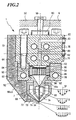
- the Fibrillianssne Trent is in the first embodiment, see. Fig. 2 , thereby reduced, that the spinning capillary 7 is heated in the region of the outlet opening 94 from the outside. This is achieved in that the heating fluid in the heating chamber 70 flows around the outer surface of the spinning capillary 7 and thus directly heats the spinning capillary 7. Due to the thin-walled design of the spinning capillary 7 and the large outer surface due to their length, a high heat transfer from the heating fluid via the spinning capillary wall to the spinning solution takes place. In order to achieve the best possible heating of the spinning capillary wall, the contact surface of the heating fluid with the outer wall of the spinning capillary should be as large as possible.
- the temperature of the heating fluid can also be safely above the decomposition temperature of the spinning solution: Due to the high speed of the spinning solution along the heated wall, the dwell time of the spinning solution in the capillary is not sufficient for the spinning solution reached the wall temperature of the spinning solution.
- the large length of the spinning capillary ensures that the wall-near layer of the spinning solution heats up. Since the viscosity decreases with increasing temperature in the conventional spinning solutions, the viscosity of the flow of the spinning solution is reduced by the spinning capillary 7 in the near-wall region. Over the large, over the entire range heated run length of the spinning capillary 7 can thus form a fuller velocity profile in the Kemströmung.
- the formation of the velocity profile along the spinning capillary 7 is in FIG. 2 schematically explained with reference to four velocity profiles A, B, C and D.
- the velocity profile A forms shortly after the distributor space 56a and is characterized by a narrow maximum in the region of the core flow, in the vicinity of the center line M. Towards the walls of the spinning capillary 7, the velocity profile A drops steeply.
- the velocity distribution in the core flow is nearly constant and drops steeply toward the walls. This is shown by the velocity profile C.
- the steep drop in the wall area is possible due to the low viscosity and the strong heating of the spinning capillary wall up to the outlet opening 94.
- the velocity profile D schematically shows a velocity profile after exit of the spinning solution from the outlet opening 94.
- the inert fluid from the chamber 72 and the spinning solution from the outlet opening 94 together form a wide jet.
- the great length compared to the diameter of the capillary and the direct heating of the capillary act together and lead to an advantageous velocity profile. It is important that the temperature of the spinning capillary wall is above the temperature of the core of the spinning solution flow in the middle of the spinning capillary.
- the temperature in the core of the spinning solution flow through the capillary 7 corresponds approximately to the operating temperature of the distributor block 6 and the holding device 60 with the pressure distribution plate 54 and the nozzle body 56 set therein by the heating channels 76, 78, 80.
- the core flow remains during the flow through the spinning capillary unaffected and does not change its temperature.
- the temperature of the spinning capillary wall 7 can be controlled precisely and with a fast response: Due to the low mass of the spinning capillary wall, the wall temperature reacts immediately to temperature changes in the heating chamber 70.
- a control device for targeted adjustment of the wall temperature and thus the targeted flow influencing of the flow through the capillary 7, a control device (not shown) may be provided.
- the control device is connected to sensors (not shown) which detect the temperature of the capillary wall and / or the heating fluid in the heating chamber 70, the flow rate of the spinning solution through the capillary and the operating pressure in the spinning solution.
- sensors not shown
- a control loop can be constructed by means of which the temperature of the wall is independently or externally adjustable to changing operating conditions.
- fluctuations of the operating parameters can be compensated without the spinning quality deteriorates.
- the fibrillation tendency can be decisively reduced if the wall of the spinning capillary 7 is also heated in the region of the outlet opening 94.
- the heating fluid from the heating chamber 72 passed through the gap 74 on the outer wall of the spinning capillary past 7 from the spinning head 8. In this way it is ensured that the spinning capillary is actually heated over its entire length and that over the length of the spinning capillary 7 forming fuller flow profile can not regress at the end of the run length due to a colder wall to this point.
- the fluid flows out of the gap 74 at a high velocity that is at least equal to the outflow velocity of the dope from the exit port 94.
- the fluid thus also acts as a transport fluid, which entrains and stabilizes the spinning solution jet.
- the fluid in the heating chamber 72 may be part of a control circuit for the wall temperature of the spinning capillary 7.
- a plurality of sensors for detecting the operating parameters of the spinning system and sensors for detecting the temperature of the spinning capillary wall and the heating fluid can be provided.
- the signals of these sensors are supplied to a temperature control device, by means of which the temperature of the heating fluid in the heating chamber 70 is regulated.
- the temperature profile along the spinning capillary in particular in the case of a large capillary length, can be controlled even more precisely in the flow direction of the spinning solution in a further embodiment.
- Each of these chambers can be provided with its own sensors.
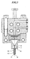
- the second embodiment according to Fig. 3 differs essentially by the structure of the heating chamber 70:
- the embodiment of Fig. 3 has only a single heating chamber 70 in the region of the spinning capillary, which reaches up to the outlet opening 94 of the individual spinning capillary 7 and forms the gap 74.
- Each spinning capillary 7 may have its own heating chamber 70, but it is also possible for a plurality of spinning capillaries 7 to be combined in a heating chamber 70.
- a second chamber 72 and a second housing 68 are not available.
- the heating chamber 70 is in the execution after Fig. 3 a tube 100 in a circular or oval design, which surrounds the outer surfaces of the spinning capillaries and forms an annular space 102 between spinning capillary 7 and housing 66.
- the annular space 102 opens as an annular gap 74.
- the heating fluid in the annular space 102 heats the entire outer wall of the spinning capillary 7 up to the outlet opening 94.
- the heating fluid is thus part of a heating device which acts directly on the spinning capillary wall and can be used for targeted control of the wall temperature.
- the tube 100 is made of a. Precision steel tube manufactured.
- the heating fluid flows out of the annular space 102 in parallel and coaxial with the spinning solution jet from the spinning solution outlet opening. As a result, a smooth guidance of the spinning solution jet can be achieved.
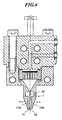
- the embodiment of Fig. 4 differs from the second embodiment in that the gap formed by the housing 66 74 is not ring-but gap-shaped.
- the housing 66 may be formed in one piece, or have two perpendicular to the center line M slidable jaws 104a, 104b. By moving the jaws in the In Fig. 4 shown arrow direction, the width of the gap 74 can be adjusted.
- no heating chamber is provided. A heating of the spinning capillary no longer takes place via a heating fluid, but via an electric heating jacket 110, which is part of the heating device of the spinning head.
- the heating jacket 110 may also be part of a control circuit for controlling the temperature of the spinning capillary wall, as described above.
- the heating jacket can be subdivided into a plurality of independently operating heating jacket segments.
Landscapes
- Engineering & Computer Science (AREA)
- Textile Engineering (AREA)
- Mechanical Engineering (AREA)
- Chemical & Material Sciences (AREA)
- Chemical Kinetics & Catalysis (AREA)
- General Chemical & Material Sciences (AREA)
- Spinning Methods And Devices For Manufacturing Artificial Fibers (AREA)
- Artificial Filaments (AREA)
- Pens And Brushes (AREA)
- Materials For Medical Uses (AREA)
Claims (36)
- Procédé de filage d'une solution de filage formée d'un mélange de cellulose, d'eau et d'oxyde d'amine tertiaire, selon lequel la solution de filage est envoyée à au moins une tête de filage caractérisé en ce que la solution de filage est guidée dans la tête de filage (8) par au moins un capillaire de filage (7), sous forme d'un tube capillaire de filage sensiblement à paroi mince ayant un diamètre constant sur sa longueur qui est équipé, au niveau de son extrémité aval, d'une ouverture de sortie de la solution de filage (94), d'où la solution de filage sort de la tête de filage, la paroi du tube capillaire de filage étante, à proximité de l'ouverture (94) de sortie de la solution de filage, à une température qui est supérieure à la température interne de la solution de filage dans le capillaire de filage et balayée tout autour au moins par segments par un fluide de chauffage.
- Procédé selon la revendication 1, caractérisé en ce que la paroi du capillaire de filage est chauffée directement par un dispositif de chauffage (70,72).
- Dispositif selon la revendication 1 ou 2, caractérisé en ce que la température de paroi du capillaire de filage (7) est réglée par un dispositif de réglage de température, à une valeur réglable.
- Procédé selon l'une des revendications indiquées précédentes, caractérisé en ce que la température de paroi du capillaire de filage (7) est réglée en fonction du débit massique de la solution de filage à l'intérieur du capillaire de filage (7).
- Procédé selon l'une des revendications précédentes, caractérisé en ce que la température de paroi du capillaire de filage (7) est réglée en fonction de la pression de filage dans la solution de filage, de préférence en fonction de la pression de filage de la solution de filage dans le capillaire de filage (7).
- Procédé selon l'une des revendications précédentes, caractérisé en ce que sous l'effet du chauffage de la paroi du capillaire de filage en fonctionnement, un profil prédéterminé de température est réglé sur la section transversale d'écoulement du capillaire de filage (7).
- Procédé selon l'une des revendications indiquées précédemment, caractérisé en ce que sous l'effet du chauffage de la paroi du capillaire de filage en fonctionnement, un profil prédéterminé de température de la paroi du capillaire de filage est réglé dans la direction d'écoulement de la solution de filage.
- Tête de filage pour le filage d'une solution de filage traversant la tête de filage et constituée par un mélange de cellulose, d'eau et d'un oxyde d'amine tertiaire, comportant au moins un capillaire de filage, qui comporte, sur son extrémité située côté aval, une ouverture de sortie pour la solution de filage, où la solution de filage sort par l'ouverture de sortie de la solution de filage hors de la tête de filage, et comportant un dispositif de chauffage commandé par la température qui agit sur la solution de filage, où lors du fonctionnement de la tête de filage, la température de paroi, produite par le dispositif de chauffage, du capillaire de filage est supérieure à la température interne de la solution de filage, dans une zone proche de l'ouverture de sortie de la solution de filage caractérisée en ce que le capillaire de filage (7) est sous forme de tube capillaire de filage sous forme d'un tube sensiblement à paroi mince de diamètre interne constant sur la longueur et le tube capillaire de filage est entouré par une chambre de chauffage (70, 72) contenant un fluide de chauffage à proximité de l'ouverture de sortie (94) de la solution de filage.
- Tête de filage selon la revendication 8, caractérisée en ce que la zone de la paroi du capillaire de filage, qui est chauffée par le dispositif de chauffage (70,72) et dont la température est supérieure à la température intérieure de la solution de filage, s'étend essentiellement jusqu'à l'ouverture (94) de sortie de la solution de filage.
- Tête de filage selon la revendication 8 ou 9, caractérisée en ce que la zone de la paroi du capillaire de filage, qui est chauffée par le dispositif de chauffage (70,72) et dont la température est supérieure à la température intérieure de la solution de filage, s'étend essentiellement sur toute la longueur du capillaire de filage (7).
- Tête de filage selon l'une des revendications 8 à 10, caractérisée en ce qu'il est prévu une unité de commande, qui agit sur le dispositif de chauffage (70,72) et à l'aide de laquelle la température de la zone de paroi directement chauffée du tube capillaire de filage (7) peut être réglée au moins par segments.
- Tête de filage selon la revendication 8, caractérisée en ce que le fluide de chauffage du dispositif de chauffage (70,72) balaye en enveloppant au moins par segments le tube capillaire de filage (7).
- Tête de filage selon l'une des revendications 8 à 12, caractérisée en ce que l'ouverture (94) de sortie de la solution de filage du tube capillaire de filage (7) est entourée au moins par segments par une ouverture en forme de fente (74), à partir de laquelle coule, en fonctionnement, un fluide de transport essentiellement dans la direction de la solution de filage qui sort par l'ouverture (94) de sortie de la solution de filage.
- Tête de filage selon la revendication 13, caractérisée en ce que la vitesse du fluide de transport, qui sort en fonctionnement de l'ouverture en forme de fente (74), correspond sensiblement au moins à la vitesse de la solution de filage qui sort de l'ouverture (94) de sortie de la solution de filage.
- Tête de filage selon l'une des revendications 13 et 14, caractérisée en ce que la chambre de chauffage (72) est reliée à l'ouverture en forme de fente (74).
- Tête de filage selon l'une des revendications 13 à 15, caractérisée en ce que le fluide de chauffage est utilisé comme fluide de transport et est dirigé depuis la chambre de chauffage (72) à travers l'ouverture en forme de fente (74).
- Tête de filage selon l'une des revendications 13 à 16, caractérisée en ce qu'entre la chambre de chauffage (70) et l'ouverture en forme de fente (74) s'étend un espace annulaire (102), qui entoure extérieurement le tube capillaire (7) essentiellement sur toute sa longueur.
- Tête de filage selon la revendication 17, caractérisée en ce que l'espace annulaire (102) possède une section transversale sensiblement ovale.
- Tête de filage selon l'une des revendications 8 à 17, caractérisée en ce que la longueur du capillaire de filage (7) est comprise entre 20 fois et 150 fois son diamètre.
- Tête de filage selon la revendication 19, caractérisée en ce que la longueur est la longueur parcourue par la solution de filage et/ou le diamètre est le diamètre intérieur du capillaire de filage (7).
- Tête de filage selon l'une des revendications 8 à 20, caractérisée en ce que la section transversale de sortie (94) est en forme de cercle.
- Tête de filage selon la revendication 21, caractérisée en ce que la section transversale de sortie (94) possède un diamètre de moins de 500 µm, de préférence de moins de 250 µm.
- Tête de filage selon l'une des revendications 8 à 22, caractérisée en ce que l'épaisseur de paroi du tube capillaire de filage (7) est inférieure à 200 µm, de préférence inférieure à 150 µm.
- Tête de filage selon l'une des revendications 8 à 23, caractérisée en ce que la température du fluide de chauffage dans la chambre de chauffage (70,72) est égale à au moins 100°C, de préférence est voisine de 150°C.
- Tête de filage selon l'une des revendications 8 à 23, caractérisée en ce que la température du fluide de chauffage dans la chambre de chauffage (70,72) est de 50°C à 150°C.
- Tête de filage selon l'une des revendications 8 à 25, caractérisée en ce que la température du fluide de chauffage dans la chambre de chauffage (70,72) est de 80°C à 150°C.
- Tête de filage selon l'une des revendications 8 à 25, caractérisée en ce que la température du fluide de chauffage dans la chambre de chauffage (70,72) est de 100°C à 150°C.
- Tête de filage selon l'une des revendications 8 à 25, caractérisée en ce que la température du fluide de chauffage dans la chambre de chauffage (70,72) est de 50°C à 180°C.
- Tête de filage selon l'une des revendications 8 à 28, caractérisée en ce qu'il est prévu au moins un capteur de température servant à détecter la température de paroi du capillaire et/ou la température de la solution de filage dans la zone de paroi du capillaire, capteur au moyen duquel la température de paroi du capillaire peut être délivrée sous la forme d'un signal électrique au dispositif de commande.
- Tête de filage selon la revendication 29, caractérisée en ce que le capteur de température est agencé sous la forme d'un élément résistif électrique.
- Tête de filage selon l'une des revendications 8 à 30, caractérisée en ce qu'il est prévu au moins un capteur de température servant à détecter la température du fluide de chauffage au moyen duquel la température du fluide de chauffage peut être délivrée au dispositif de commande sous la forme d'un signal électrique.
- Tête de filage selon l'une des revendications 8 à 31, caractérisée en ce que la fente (74) est formée par un boîtier (100;104a,104b) qui est mobile au moins par segments transversalement par rapport à l'axe longitudinal du capillaire de filage, et la section transversale d'écoulement de la fente (74) est modifiable.
- Installation de filage comportant un récipient de compensation de pression, qui contient une solution de filage formée de cellulose, d'eau et d'un oxyde d'amine tertiaire, ainsi qu'un ou plusieurs dispositifs de stabilisation, comportant une tête de filage ou plusieurs têtes de filage, à l'aide de laquelle ou desquelles la solution de filage peut être filée pour former des corps de forme, et comportant une canalisation pour la solution de filage, par laquelle la solution de filage est envoyée du récipient de compensation de pression à la tête de filage ou aux têtes de filage, caractérisée en ce que la tête de filage (8) est agencée selon l'une des revendications 8 à 32 et/ou en ce que l'installation de filage (1) est agencée pour la mise en oeuvre du procédé selon l'une des revendications 1 à 7.
- Installation de filage selon la revendication 33, caractérisée en ce que l'installation de filage comporte, après la tête de filage (8) ou les têtes de filage (8), une fente (10), dans laquelle la solution de filage coule après sa sortie de l'ouverture (94) de sortie de la solution de filage et dans laquelle elle est étirée.
- Installation de filage selon la revendication 33 ou 34, caractérisée en ce que l'installation de filage (1) comporte, en aval de la fente (10), un bain de précipitation (11), dans lequel la solution de filage, qui sort de la tête de filage (8), pénètre après traversée de la fente et étirage pour constituer des corps de forme (10).
- Installation de filage selon l'une des revendications 33 à 35, caractérisée en ce qu'il est prévu un dispositif de tirage (12), au moyen duquel la solution de filage peut être tirée du bain de précipitation sous la forme de fils ou de corps de forme qui ont précipité.
Applications Claiming Priority (3)
| Application Number | Priority Date | Filing Date | Title |
|---|---|---|---|
| DE10019660 | 2000-04-20 | ||
| DE10019660A DE10019660B4 (de) | 2000-04-20 | 2000-04-20 | Verfahren zum Verspinnen einer Spinnlösung und Spinnkopf |
| PCT/EP2001/004467 WO2001081663A1 (fr) | 2000-04-20 | 2001-04-19 | Tete de filage et procede de filage d'une solution de filage |
Publications (3)
| Publication Number | Publication Date |
|---|---|
| EP1276922A1 EP1276922A1 (fr) | 2003-01-22 |
| EP1276922B1 EP1276922B1 (fr) | 2004-12-29 |
| EP1276922B2 true EP1276922B2 (fr) | 2008-07-09 |
Family
ID=7639492
Family Applications (1)
| Application Number | Title | Priority Date | Filing Date |
|---|---|---|---|
| EP01936252A Expired - Lifetime EP1276922B2 (fr) | 2000-04-20 | 2001-04-19 | Tete de filage et procede de filage d'une solution de filage |
Country Status (15)
| Country | Link |
|---|---|
| US (1) | US20030155673A1 (fr) |
| EP (1) | EP1276922B2 (fr) |
| KR (1) | KR100500279B1 (fr) |
| CN (1) | CN1232682C (fr) |
| AT (1) | ATE286160T1 (fr) |
| AU (1) | AU2001262211A1 (fr) |
| BR (1) | BR0110432A (fr) |
| CA (1) | CA2406765C (fr) |
| DE (2) | DE10019660B4 (fr) |
| EA (1) | EA003589B1 (fr) |
| MY (1) | MY128277A (fr) |
| NO (1) | NO321686B1 (fr) |
| TW (1) | TW565632B (fr) |
| WO (1) | WO2001081663A1 (fr) |
| ZA (1) | ZA200209329B (fr) |
Families Citing this family (20)
| Publication number | Priority date | Publication date | Assignee | Title |
|---|---|---|---|---|
| DE10112050B4 (de) * | 2001-03-14 | 2004-02-12 | Thüringisches Institut für Textil- und Kunststoff-Forschung e.V. | Verfahren und Vorrichtung zur Herstellung von Cellulosefasern und Cellulosefilamentgarnen |
| DE10200405A1 (de) | 2002-01-08 | 2002-08-01 | Zimmer Ag | Spinnvorrichtung und -verfahren mit Kühlbeblasung |
| DE10204381A1 (de) | 2002-01-28 | 2003-08-07 | Zimmer Ag | Ergonomische Spinnanlage |
| DE10206089A1 (de) | 2002-02-13 | 2002-08-14 | Zimmer Ag | Bersteinsatz |
| DE102004024030A1 (de) | 2004-05-13 | 2005-12-08 | Zimmer Ag | Lyocell-Verfahren mit polymerisationsgradabhängiger Einstellung der Verarbeitungsdauer |
| KR100595751B1 (ko) * | 2004-11-11 | 2006-07-03 | 주식회사 효성 | 셀룰로오스 멀티 필라멘트의 제조방법 |
| DE102005040000B4 (de) * | 2005-08-23 | 2010-04-01 | Lenzing Ag | Mehrfachspinndüsenanordnung und Verfahren mit Absaugung und Beblasung |
| CN100553662C (zh) * | 2006-07-18 | 2009-10-28 | 中国人民解放军第二军医大学 | 一种抗肿瘤的中药组合物及其制备方法 |
| JP5490724B2 (ja) * | 2008-02-08 | 2014-05-14 | リスト ホールディング アーゲー | 成形物の製造方法及び装置 |
| MY175143A (en) | 2010-04-08 | 2020-06-10 | Manuel Steiner | Process for producing a product |
| CN103015082B (zh) * | 2012-12-25 | 2014-08-13 | 西安建筑科技大学 | 一种纺丝头及利用其制备编织管/聚合物复合膜的方法 |
| US11124895B2 (en) * | 2013-10-29 | 2021-09-21 | Braskem America, Inc. | System and method for measuring out a polymer and first solvent mixture, device, system and method for extracting a solvent from at least one polymer strand, system and method for mechanically pre-recovering at least one liquid from at least one polymer strand, and a continuous system and method for the production of at least one polymer strand |
| TWI667378B (zh) | 2014-01-03 | 2019-08-01 | 奧地利商蘭精股份有限公司 | 纖維素纖維 |
| CN103938283A (zh) * | 2014-04-25 | 2014-07-23 | 吕赛林 | 用于制造竹浆高溶功能纤维的喷丝板 |
| CN105332064B (zh) * | 2015-12-02 | 2018-01-12 | 苏州布舞佳乡纺织科技有限公司 | 一种用于纺织的纤维制造装置 |
| CN108298498B (zh) * | 2017-01-13 | 2019-12-10 | 北京赛特超润界面科技有限公司 | 一种弹簧导液浸润装置 |
| EP3467161A1 (fr) * | 2017-10-06 | 2019-04-10 | Lenzing Aktiengesellschaft | Procédé de production d'un filament de cellulose de type lyocell |
| EP3511449B1 (fr) * | 2018-01-15 | 2022-03-23 | Lenzing Aktiengesellschaft | Recyclage de la cellulose lyocell pour procédé lyocell |
| CN112176430B (zh) * | 2020-09-21 | 2021-08-27 | 浙江永宁药业股份有限公司 | 一种口罩熔喷布生产用恒温型喷头 |
| CN114277452B (zh) * | 2022-01-26 | 2023-01-06 | 中国纺织科学研究院有限公司 | 干喷湿纺法纺丝设备 |
Citations (2)
| Publication number | Priority date | Publication date | Assignee | Title |
|---|---|---|---|---|
| US3437725A (en) † | 1967-08-29 | 1969-04-08 | Du Pont | Melt spinning apparatus and method |
| WO1998026122A1 (fr) † | 1996-12-10 | 1998-06-18 | Acordis Fibres (Holdings) Limited | Procede de fabrication d'un textile non tisse |
Family Cites Families (12)
| Publication number | Priority date | Publication date | Assignee | Title |
|---|---|---|---|---|
| US4317790A (en) * | 1979-02-21 | 1982-03-02 | American Cyanamid Company | Spinning process |
| EP0095712B2 (fr) * | 1982-05-28 | 1993-06-23 | Asahi Kasei Kogyo Kabushiki Kaisha | Fibres en téréphtalate de polyéthylène pouvant être aisément teintes, et procédé pour leur fabrication |
| JPS61194204A (ja) * | 1985-02-21 | 1986-08-28 | Teijin Ltd | 紡糸口金装置 |
| US5264173A (en) * | 1989-05-24 | 1993-11-23 | Masatsugu Mochizuki | Polyvinyl alcohol monofilament yarns and process for producing the same |
| US5652001A (en) * | 1993-05-24 | 1997-07-29 | Courtaulds Fibres Limited | Spinnerette |
| AT399729B (de) * | 1993-07-01 | 1995-07-25 | Chemiefaser Lenzing Ag | Verfahren zur herstellung cellulosischer fasern sowie vorrichtung zur durchführung des verfahrens und deren verwendung |
| AT403531B (de) * | 1994-08-10 | 1998-03-25 | Chemiefaser Lenzing Ag | Vorrichtung zum regeln des druckes in einer strömenden, viskosen masse |
| DE4430828C2 (de) * | 1994-08-31 | 2001-05-31 | Thueringisches Inst Textil | Verfahren zum Fibrillieren von lösungsmittelgesponnenen Cellulosefilamentgarnen |
| AT401063B (de) * | 1994-09-05 | 1996-06-25 | Chemiefaser Lenzing Ag | Verfahren zur herstellung von cellulosischen formkörpern |
| US5984655A (en) * | 1994-12-22 | 1999-11-16 | Lenzing Aktiengesellschaft | Spinning process and apparatus |
| US6210801B1 (en) * | 1996-08-23 | 2001-04-03 | Weyerhaeuser Company | Lyocell fibers, and compositions for making same |
| US6336801B1 (en) * | 1999-06-21 | 2002-01-08 | Kimberly-Clark Worldwide, Inc. | Die assembly for a meltblowing apparatus |
-
2000
- 2000-04-20 DE DE10019660A patent/DE10019660B4/de not_active Expired - Fee Related
-
2001
- 2001-04-18 MY MYPI20011837A patent/MY128277A/en unknown
- 2001-04-19 AU AU2001262211A patent/AU2001262211A1/en not_active Abandoned
- 2001-04-19 AT AT01936252T patent/ATE286160T1/de not_active IP Right Cessation
- 2001-04-19 EP EP01936252A patent/EP1276922B2/fr not_active Expired - Lifetime
- 2001-04-19 EA EA200201118A patent/EA003589B1/ru not_active IP Right Cessation
- 2001-04-19 BR BR0110432-2A patent/BR0110432A/pt active Search and Examination
- 2001-04-19 CN CNB018098207A patent/CN1232682C/zh not_active Expired - Fee Related
- 2001-04-19 US US10/258,058 patent/US20030155673A1/en not_active Abandoned
- 2001-04-19 DE DE50104967T patent/DE50104967D1/de not_active Expired - Fee Related
- 2001-04-19 KR KR10-2002-7014128A patent/KR100500279B1/ko not_active IP Right Cessation
- 2001-04-19 WO PCT/EP2001/004467 patent/WO2001081663A1/fr active IP Right Grant
- 2001-04-19 CA CA002406765A patent/CA2406765C/fr not_active Expired - Fee Related
- 2001-06-20 TW TW090109080A patent/TW565632B/zh not_active IP Right Cessation
-
2002
- 2002-10-21 NO NO20025047A patent/NO321686B1/no unknown
- 2002-11-15 ZA ZA200209329A patent/ZA200209329B/en unknown
Patent Citations (2)
| Publication number | Priority date | Publication date | Assignee | Title |
|---|---|---|---|---|
| US3437725A (en) † | 1967-08-29 | 1969-04-08 | Du Pont | Melt spinning apparatus and method |
| WO1998026122A1 (fr) † | 1996-12-10 | 1998-06-18 | Acordis Fibres (Holdings) Limited | Procede de fabrication d'un textile non tisse |
Also Published As
| Publication number | Publication date |
|---|---|
| EP1276922B1 (fr) | 2004-12-29 |
| US20030155673A1 (en) | 2003-08-21 |
| CA2406765C (fr) | 2007-01-09 |
| CA2406765A1 (fr) | 2002-10-18 |
| DE50104967D1 (de) | 2005-02-03 |
| AU2001262211A1 (en) | 2001-11-07 |
| EA200201118A1 (ru) | 2003-02-27 |
| ATE286160T1 (de) | 2005-01-15 |
| DE10019660A1 (de) | 2000-10-26 |
| EP1276922A1 (fr) | 2003-01-22 |
| NO321686B1 (no) | 2006-06-19 |
| MY128277A (en) | 2007-01-31 |
| NO20025047D0 (no) | 2002-10-21 |
| CN1232682C (zh) | 2005-12-21 |
| BR0110432A (pt) | 2003-02-11 |
| EA003589B1 (ru) | 2003-06-26 |
| TW565632B (en) | 2003-12-11 |
| NO20025047L (no) | 2002-12-04 |
| WO2001081663A8 (fr) | 2002-02-21 |
| DE10019660B4 (de) | 2004-04-29 |
| WO2001081663A1 (fr) | 2001-11-01 |
| KR20020093934A (ko) | 2002-12-16 |
| ZA200209329B (en) | 2004-02-16 |
| CN1430684A (zh) | 2003-07-16 |
| KR100500279B1 (ko) | 2005-07-11 |
Similar Documents
| Publication | Publication Date | Title |
|---|---|---|
| EP1276922B2 (fr) | Tete de filage et procede de filage d'une solution de filage | |
| AT403584B (de) | Verfahren und vorrichtung zur herstellung cellulosischer flach- oder schlauchfolien | |
| EP1902164B1 (fr) | Dispositif de filature et procede pour produire des fils fins par epissurage afin d'obtenir un nontisse, et nontisse susceptible d'etre obtenu ainsi | |
| EP1192301B1 (fr) | Procede et dispositif pour produire des fils fins sensiblement continus | |
| DE10065859B4 (de) | Verfahren und Vorrichtung zur Herstellung von im Wesentlichen endlosen feinen Fäden | |
| EP3692188B1 (fr) | Dispositif permettant l'extrusion de filaments et la fabrication de non-tissés meltspun | |
| DE2116254C2 (de) | Vorrichtung zum kontinuierlichen Extrudieren hochviskoser Schmelzen | |
| DE1435632B2 (de) | Verfahren zum entspannungsspinnen von fibrilliertem, plexusfadenartigem material | |
| EP2565304A1 (fr) | Procédé et dispositif d'extrusion | |
| DE10112050B4 (de) | Verfahren und Vorrichtung zur Herstellung von Cellulosefasern und Cellulosefilamentgarnen | |
| DE60012152T2 (de) | Schmelzspinnen mit hoher geschwindigkeit von fasern aus fluorpolymeren | |
| DE4219658C3 (de) | Verfahren zur Herstellung von Cellulosefasern -filamenten und -folien nach dem Trocken-Naßextrusionsverfahren | |
| EP3844328B1 (fr) | Procédé et dispositif de filage des filaments à déviation | |
| WO1996005338A9 (fr) | Dispositif et installation utilises dans le traitement de solutions de cellulose | |
| EP0455897A1 (fr) | Dispositif pour la fabrication de fibres trés fines | |
| AT410195B (de) | Verfahren und einrichtung zur anpassung eines extrusionswerkzeuges an einen extruder | |
| DE3331543C2 (fr) | ||
| WO2001032397A1 (fr) | Dispositif pour determiner l'etat de marche d'une extrudeuse | |
| EP1285107B1 (fr) | Procede pour extruder un corps moule continu | |
| DE19716394C1 (de) | Verfahren und Vorrichtung zur passiven verzögerten Abkühlung von Spinnfilamenten | |
| DE60216617T2 (de) | Fällbad, und Verfahren, welches dieses Fällbad verwendet | |
| EP1287189B1 (fr) | Procede pour l'extrusion d'un corps moule sans fin | |
| DE19732458C1 (de) | Vorrichtung und Verfahren zur Filtration von hochviskosen Polymerschmelzen | |
| DE19962398A1 (de) | Kühlvorrichtung zur Kühlung synthetischer Fäden | |
| DE10060877A1 (de) | Spinntrichtervorrichtung mit Mitteneinspeisung |
Legal Events
| Date | Code | Title | Description |
|---|---|---|---|
| PUAI | Public reference made under article 153(3) epc to a published international application that has entered the european phase |
Free format text: ORIGINAL CODE: 0009012 |
|
| 17P | Request for examination filed |
Effective date: 20020906 |
|
| AK | Designated contracting states |
Kind code of ref document: A1 Designated state(s): AT BE CH CY DE DK ES FI FR GB GR IE IT LI LU MC NL PT SE TR |
|
| AX | Request for extension of the european patent |
Free format text: AL;LT;LV;MK;RO;SI |
|
| 17Q | First examination report despatched |
Effective date: 20040414 |
|
| GRAP | Despatch of communication of intention to grant a patent |
Free format text: ORIGINAL CODE: EPIDOSNIGR1 |
|
| GRAS | Grant fee paid |
Free format text: ORIGINAL CODE: EPIDOSNIGR3 |
|
| GRAA | (expected) grant |
Free format text: ORIGINAL CODE: 0009210 |
|
| AK | Designated contracting states |
Kind code of ref document: B1 Designated state(s): AT BE CH CY DE DK ES FI FR GB GR IE IT LI LU MC NL PT SE TR |
|
| PG25 | Lapsed in a contracting state [announced via postgrant information from national office to epo] |
Ref country code: IT Free format text: LAPSE BECAUSE OF FAILURE TO SUBMIT A TRANSLATION OF THE DESCRIPTION OR TO PAY THE FEE WITHIN THE PRESCRIBED TIME-LIMIT;WARNING: LAPSES OF ITALIAN PATENTS WITH EFFECTIVE DATE BEFORE 2007 MAY HAVE OCCURRED AT ANY TIME BEFORE 2007. THE CORRECT EFFECTIVE DATE MAY BE DIFFERENT FROM THE ONE RECORDED. Effective date: 20041229 Ref country code: IE Free format text: LAPSE BECAUSE OF FAILURE TO SUBMIT A TRANSLATION OF THE DESCRIPTION OR TO PAY THE FEE WITHIN THE PRESCRIBED TIME-LIMIT Effective date: 20041229 Ref country code: FR Free format text: LAPSE BECAUSE OF FAILURE TO SUBMIT A TRANSLATION OF THE DESCRIPTION OR TO PAY THE FEE WITHIN THE PRESCRIBED TIME-LIMIT Effective date: 20041229 Ref country code: NL Free format text: LAPSE BECAUSE OF FAILURE TO SUBMIT A TRANSLATION OF THE DESCRIPTION OR TO PAY THE FEE WITHIN THE PRESCRIBED TIME-LIMIT Effective date: 20041229 Ref country code: TR Free format text: LAPSE BECAUSE OF FAILURE TO SUBMIT A TRANSLATION OF THE DESCRIPTION OR TO PAY THE FEE WITHIN THE PRESCRIBED TIME-LIMIT Effective date: 20041229 Ref country code: FI Free format text: LAPSE BECAUSE OF FAILURE TO SUBMIT A TRANSLATION OF THE DESCRIPTION OR TO PAY THE FEE WITHIN THE PRESCRIBED TIME-LIMIT Effective date: 20041229 |
|
| REG | Reference to a national code |
Ref country code: GB Ref legal event code: FG4D Free format text: NOT ENGLISH |
|
| REG | Reference to a national code |
Ref country code: CH Ref legal event code: EP |
|
| GBT | Gb: translation of ep patent filed (gb section 77(6)(a)/1977) |
Effective date: 20041230 |
|
| REG | Reference to a national code |
Ref country code: IE Ref legal event code: FG4D Free format text: GERMAN |
|
| REF | Corresponds to: |
Ref document number: 50104967 Country of ref document: DE Date of ref document: 20050203 Kind code of ref document: P |
|
| PG25 | Lapsed in a contracting state [announced via postgrant information from national office to epo] |
Ref country code: GR Free format text: LAPSE BECAUSE OF FAILURE TO SUBMIT A TRANSLATION OF THE DESCRIPTION OR TO PAY THE FEE WITHIN THE PRESCRIBED TIME-LIMIT Effective date: 20050329 Ref country code: SE Free format text: LAPSE BECAUSE OF FAILURE TO SUBMIT A TRANSLATION OF THE DESCRIPTION OR TO PAY THE FEE WITHIN THE PRESCRIBED TIME-LIMIT Effective date: 20050329 Ref country code: DK Free format text: LAPSE BECAUSE OF FAILURE TO SUBMIT A TRANSLATION OF THE DESCRIPTION OR TO PAY THE FEE WITHIN THE PRESCRIBED TIME-LIMIT Effective date: 20050329 |
|
| PG25 | Lapsed in a contracting state [announced via postgrant information from national office to epo] |
Ref country code: ES Free format text: LAPSE BECAUSE OF FAILURE TO SUBMIT A TRANSLATION OF THE DESCRIPTION OR TO PAY THE FEE WITHIN THE PRESCRIBED TIME-LIMIT Effective date: 20050409 |
|
| PG25 | Lapsed in a contracting state [announced via postgrant information from national office to epo] |
Ref country code: CY Free format text: LAPSE BECAUSE OF FAILURE TO SUBMIT A TRANSLATION OF THE DESCRIPTION OR TO PAY THE FEE WITHIN THE PRESCRIBED TIME-LIMIT Effective date: 20050419 Ref country code: LU Free format text: LAPSE BECAUSE OF NON-PAYMENT OF DUE FEES Effective date: 20050419 |
|
| PG25 | Lapsed in a contracting state [announced via postgrant information from national office to epo] |
Ref country code: BE Free format text: LAPSE BECAUSE OF NON-PAYMENT OF DUE FEES Effective date: 20050430 Ref country code: CH Free format text: LAPSE BECAUSE OF NON-PAYMENT OF DUE FEES Effective date: 20050430 Ref country code: MC Free format text: LAPSE BECAUSE OF NON-PAYMENT OF DUE FEES Effective date: 20050430 Ref country code: LI Free format text: LAPSE BECAUSE OF NON-PAYMENT OF DUE FEES Effective date: 20050430 |
|
| NLV1 | Nl: lapsed or annulled due to failure to fulfill the requirements of art. 29p and 29m of the patents act | ||
| REG | Reference to a national code |
Ref country code: IE Ref legal event code: FD4D |
|
| PLBI | Opposition filed |
Free format text: ORIGINAL CODE: 0009260 |
|
| BERE | Be: lapsed |
Owner name: ZIMMER A.G. Effective date: 20050430 |
|
| PLAX | Notice of opposition and request to file observation + time limit sent |
Free format text: ORIGINAL CODE: EPIDOSNOBS2 |
|
| 26 | Opposition filed |
Opponent name: LENZING AKTIENGESELLSCHAFT Effective date: 20050929 |
|
| REG | Reference to a national code |
Ref country code: CH Ref legal event code: PL |
|
| EN | Fr: translation not filed | ||
| PLAF | Information modified related to communication of a notice of opposition and request to file observations + time limit |
Free format text: ORIGINAL CODE: EPIDOSCOBS2 |
|
| PLAF | Information modified related to communication of a notice of opposition and request to file observations + time limit |
Free format text: ORIGINAL CODE: EPIDOSCOBS2 |
|
| PLAF | Information modified related to communication of a notice of opposition and request to file observations + time limit |
Free format text: ORIGINAL CODE: EPIDOSCOBS2 |
|
| PLAF | Information modified related to communication of a notice of opposition and request to file observations + time limit |
Free format text: ORIGINAL CODE: EPIDOSCOBS2 |
|
| PLBB | Reply of patent proprietor to notice(s) of opposition received |
Free format text: ORIGINAL CODE: EPIDOSNOBS3 |
|
| PLBP | Opposition withdrawn |
Free format text: ORIGINAL CODE: 0009264 |
|
| BERE | Be: lapsed |
Owner name: *ZIMMER A.G. Effective date: 20050430 |
|
| PG25 | Lapsed in a contracting state [announced via postgrant information from national office to epo] |
Ref country code: PT Free format text: LAPSE BECAUSE OF NON-PAYMENT OF DUE FEES Effective date: 20050529 |
|
| PUAH | Patent maintained in amended form |
Free format text: ORIGINAL CODE: 0009272 |
|
| STAA | Information on the status of an ep patent application or granted ep patent |
Free format text: STATUS: PATENT MAINTAINED AS AMENDED |
|
| 27A | Patent maintained in amended form |
Effective date: 20080709 |
|
| AK | Designated contracting states |
Kind code of ref document: B2 Designated state(s): AT BE CH CY DE DK ES FI FR GB GR IE IT LI LU MC NL PT SE TR |
|
| PLAB | Opposition data, opponent's data or that of the opponent's representative modified |
Free format text: ORIGINAL CODE: 0009299OPPO |
|
| REG | Reference to a national code |
Ref country code: ES Ref legal event code: FD2A Effective date: 20050420 |
|
| PGFP | Annual fee paid to national office [announced via postgrant information from national office to epo] |
Ref country code: AT Payment date: 20080415 Year of fee payment: 8 |
|
| PG25 | Lapsed in a contracting state [announced via postgrant information from national office to epo] |
Ref country code: ES Free format text: LAPSE BECAUSE OF FAILURE TO SUBMIT A TRANSLATION OF THE DESCRIPTION OR TO PAY THE FEE WITHIN THE PRESCRIBED TIME-LIMIT Effective date: 20050420 |
|
| PGFP | Annual fee paid to national office [announced via postgrant information from national office to epo] |
Ref country code: GB Payment date: 20080421 Year of fee payment: 8 |
|
| PGFP | Annual fee paid to national office [announced via postgrant information from national office to epo] |
Ref country code: DE Payment date: 20090422 Year of fee payment: 9 |
|
| GBPC | Gb: european patent ceased through non-payment of renewal fee |
Effective date: 20090419 |
|
| PG25 | Lapsed in a contracting state [announced via postgrant information from national office to epo] |
Ref country code: AT Free format text: LAPSE BECAUSE OF NON-PAYMENT OF DUE FEES Effective date: 20090419 |
|
| PG25 | Lapsed in a contracting state [announced via postgrant information from national office to epo] |
Ref country code: GB Free format text: LAPSE BECAUSE OF NON-PAYMENT OF DUE FEES Effective date: 20090419 |
|
| PG25 | Lapsed in a contracting state [announced via postgrant information from national office to epo] |
Ref country code: DE Free format text: LAPSE BECAUSE OF NON-PAYMENT OF DUE FEES Effective date: 20101103 |