EP1266854B1 - Dispositif de transport de feuilles et méthode pour assembler des feuilles - Google Patents
Dispositif de transport de feuilles et méthode pour assembler des feuilles Download PDFInfo
- Publication number
- EP1266854B1 EP1266854B1 EP02008873A EP02008873A EP1266854B1 EP 1266854 B1 EP1266854 B1 EP 1266854B1 EP 02008873 A EP02008873 A EP 02008873A EP 02008873 A EP02008873 A EP 02008873A EP 1266854 B1 EP1266854 B1 EP 1266854B1
- Authority
- EP
- European Patent Office
- Prior art keywords
- sheets
- quires
- suction
- conveying
- conveying apparatus
- Prior art date
- Legal status (The legal status is an assumption and is not a legal conclusion. Google has not performed a legal analysis and makes no representation as to the accuracy of the status listed.)
- Expired - Lifetime
Links
Images


Classifications
-
- B—PERFORMING OPERATIONS; TRANSPORTING
- B65—CONVEYING; PACKING; STORING; HANDLING THIN OR FILAMENTARY MATERIAL
- B65H—HANDLING THIN OR FILAMENTARY MATERIAL, e.g. SHEETS, WEBS, CABLES
- B65H29/00—Delivering or advancing articles from machines; Advancing articles to or into piles
- B65H29/66—Advancing articles in overlapping streams
- B65H29/6609—Advancing articles in overlapping streams forming an overlapping stream
- B65H29/6618—Advancing articles in overlapping streams forming an overlapping stream upon transfer from a first conveyor to a second conveyor advancing at slower speed
- B65H29/6627—Advancing articles in overlapping streams forming an overlapping stream upon transfer from a first conveyor to a second conveyor advancing at slower speed in combination with auxiliary means for overlapping articles
-
- B—PERFORMING OPERATIONS; TRANSPORTING
- B65—CONVEYING; PACKING; STORING; HANDLING THIN OR FILAMENTARY MATERIAL
- B65H—HANDLING THIN OR FILAMENTARY MATERIAL, e.g. SHEETS, WEBS, CABLES
- B65H2301/00—Handling processes for sheets or webs
- B65H2301/50—Auxiliary process performed during handling process
- B65H2301/51—Modifying a characteristic of handled material
- B65H2301/513—Modifying electric properties
- B65H2301/5132—Bringing electrostatic charge
-
- B—PERFORMING OPERATIONS; TRANSPORTING
- B65—CONVEYING; PACKING; STORING; HANDLING THIN OR FILAMENTARY MATERIAL
- B65H—HANDLING THIN OR FILAMENTARY MATERIAL, e.g. SHEETS, WEBS, CABLES
- B65H2406/00—Means using fluid
- B65H2406/30—Suction means
-
- B—PERFORMING OPERATIONS; TRANSPORTING
- B65—CONVEYING; PACKING; STORING; HANDLING THIN OR FILAMENTARY MATERIAL
- B65H—HANDLING THIN OR FILAMENTARY MATERIAL, e.g. SHEETS, WEBS, CABLES
- B65H2406/00—Means using fluid
- B65H2406/30—Suction means
- B65H2406/32—Suction belts
Definitions
- the invention relates to a conveyor for sheet layers, which in particular at least one collecting area can be fed, with at least two successively arranged conveying devices, of which the forward conveying device in the conveying direction has a lower speed than the rear, wherein at least one ionizer is included, by means of which the sheet layers electrostatically are rechargeable.
- the invention further relates to a method for bringing sheet layers together.
- a generic conveyor or conveyor in which in particular by means of an ionizing the sheet and at least one of the conveyor belts is electrostatically charged, so as to allow an electrostatic braking of the bow.
- DE-AS 1 245 702 discloses a device for conveying, overlapping and depositing, for example, sheets of paper or the like ejected from cross-cutters with a conveyor belt and a further conveyor belt of lower speed connected downstream of it and arranged lower in the conveying direction. In this case, individual sheets are tightened on a slowly moving belt, the so-called. Abbremsband by suction. A device acc. This document is not suitable for several superimposed sheets, so-called sheet layers or paper clips.
- the at least one region of the sheet layers is arranged in the conveying direction in the rear region of the sheet layers, in particular in the vicinity of the edge of the respective sheet layer, it is possible long format sections or long sheet layers at a slower speed in the slow conveyor, ie the front conveyor to transport, as this has been possible. Furthermore, this means a non-contact braking of the sheet layers at the trailing edge, whereby no damage to the leading edge takes place even at high paper web speeds or sheet speeds.
- the long format sections or sheet layers are no longer pushed together in the braking phase, as this happens in the otherwise conventional inertia of sheet layers when braking at the front edge.
- the front conveyor device comprises suction openings.
- suction openings By providing suction openings in the front conveyor, in particular in corresponding conveyor belts, a particularly simple constructive and inventive design of the front conveyor possible.
- the suction openings pass through at least one conveyor belt of the front conveyor.
- the at least one conveyor belt can then be called, for example, also suction belt.
- a plurality of juxtaposed conveyor belts or suction belts are preferably used. These are preferably three.
- the suction device comprises at least one suction box with suction slots, which can be brought into operative connection with the suction openings. If the suction openings are arranged at a predeterminable, in particular uniform, distance from one another on the at least one conveyor belt, a format-independent overlapping distance can be selected. The overlap distance is accordingly preferably adaptable and depends on the hole spacing of the corresponding suction holes in the at least one conveyor belt.
- a particularly effective ionization or electrical charging of the sheet layers can be realized if the conveying device or at least one further element is at least partially electrically conductive in the region of the ionizing device.
- an electrically conductive element is preferably provided, which is in particular stationary.
- a particularly preferred embodiment of the conveyor device according to the invention is realized when a phase shift as a function of the speed of the conveyor between the at least two is provided behind one another arranged conveying devices.
- the phase shift serves to compensate for the inertia of the sheet layers to higher speeds of the conveyor.
- the higher the speed of the sheet layers the sheet layers to slip over the corresponding suction holes, before a complete fixation is done by the suction air to the corresponding conveyor belt.
- there is a linear relationship between the phase shift and the speed of the conveyor is preferably, the greater the speed of the conveyor, the more the phase of the front conveyor of the phase of the rear conveyor.
- a paper processing machine is provided with at least one of the aforementioned conveyors.
- Such a paper processing machine processes in particular paper, but also so-called. Tissue.
- Such a paper processing machine serves, in particular, to cut, stack and package paper as well as tissue.
- the object is further achieved by a method for bringing together sheet layers with the method steps of claim 12.
- the inventive method steps it is possible to bring together without slipping the sheet in the sheet layers, in particular on a slower conveyor belt or Abbremsband and in particular to overlap, with a very fast process control and a very gentle process management is possible. Furthermore, it is possible to set the difference in speeds between the supplied sheet layers and the overlapping sheet layers significantly higher, so that a slower striking the overlapping sheet layers on the front stop a collection box a corresponding paper processing machine is possible, making this attack is also gentle. As a result of the slow impact on the front stop, the sheet layers brought to overlap are thus gently accumulated, preferably subsequently to the abovementioned method steps, to form a sheet stack.
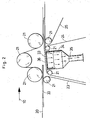
- Fig. 1 shows a side view of the essential part of a conveyor according to the invention.
- Paper clips 33 are between a top belt 20 and a conveyor belt 23 in the conveying direction 10 in the direction a Abbremsbandes 24 transported.
- the upper belt 20 is deflected by means of deflection rollers 21 and by means of a drive roller or a drive unit, which is not shown in Fig. 1, driven. Accordingly, the conveyor belt 23 is deflected via deflection rollers 21 and driven by a drive roller 22. The same applies to the Abbremsband 24 and the lower band 25th
- the paper clips consisting of some paper sheets, such as 4 to 7 sheets, are electrically charged by means of an ionizer 30 provided with an electrical connection 31 and the electrostatic field 32 produced thereby, so that the paper sheets are held together in the respective paper clip 33 ,
- a counter electrode 27 is preferably provided, which is preferably electrically conductive.
- a corresponding ionizer which may be, for example, an electrically conductive rod, which may be connected to a van der Graf generator or other commercially available high voltage source, is known, for example from DE-PS 2,100,980.
- a suction box 34 is provided in this embodiment, which is shown broken in Fig. 1.
- FIG. 2 shows a detail of FIG. 1 in more detail.
- the suction slot 36 of the suction box 34 is shown more clearly in this figure.
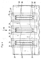
- Fig. 3 is a plan view of a portion of the conveyor of FIG. 1 is shown schematically. It is a machine frame 40 and a carrier 41 is shown, wherein above the carrier 41 are each three suction boxes side by side each side by side led stream of paper clips 33 are provided. In particular, the suction slots 36 and the suction holes 37 are shown.
- a lower paper clip 38 is shown by 38 and a line from bottom left to top right and only schematically on the right side of the two Pandaclipströme.
- an upper paper clip 33 is shown, which is lined from top left to bottom right. This ruling has been made for the sake of clarity. It can be seen that the suction holes 37 located at the top in FIG.
- suction holes 37 lie in the region of the suction slots 36, that is to say that suction air acts on the paper clip 33 lying on top.
- the bottom in Fig. 3rd shown suction holes 37 are outside the range of the suction slots 36, so that no more suction occurs through this.
- the lower paper clip 38 is no longer held by suction, but only by the weight itself.
- the Abbremsb section 24 and brake belts are indicated in Fig. 3 only. These are extended further upwards and downwards in FIG. 3 as well as in FIG. 4 to introduce, whereby suction holes 37 are provided correspondingly at preferably equidistant intervals.
- FIG. 4 a detail of Fig. 3 is shown in detail.
- the thin lines drawn in Fig. 4 are under objects that are above them.
- a lower paper clip 38 and an upper paper clip 33 are shown, wherein the upper paper clip 33 has been interrupted in the lower region of FIG.
- both the Abbremsb section 24 and the suction boxes 34 are below the paper clips 33 and 38.
- the suction box 34 with the suction slots 36 is further below the Abbremsb selected 24 with the suction holes 37 located in these.
- a paper clip 33 is electrostatically charged by means of the ionizer 30 and optionally the counter electrode 27, so that the paper clips or the sheets are held together in the paper clip.
- the paper clips 33 are brought to overlap, being transported in the rear region of the just in the overlap area Paper clip 33 suction air is applied. This happens in that at the moment where the rear portion of the clip 33 enters the overlap region, the corresponding suction holes 37 of the Abbremsb suitable 24 are brought into the effective range of the suction box 34, ie above the respective suction slots 36.
- the paper clip 33 is held by the suction air as long as the suction holes 37, which are in engagement with the suction slot 36, are still in engagement therewith. Once they are outside the range of the suction slots, no suction air is passed through the suction openings, so that the tightening of the paper clips 33 is terminated by means of the suction air.
- the paper clips In the further course of conveying the paper clips they are pushed together in a front stop, which is not shown in the figures, and indeed to stacks of paper.
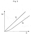
- FIG. 5 shows a diagram in which two functions of the phase shift 50 are shown as a function of the machine speed 51.
- a linear function is shown and with 53 another function, for example, at low machine speeds an exponential or quadratic Rise is provided and to higher machine speeds a linear course.
- the size of the suction openings, the size of the paper clips, the size of the vertical distance for example.
- the roughness of the paper and / or the suction power for example, the suction boxes or the number the suction boxes, different functional characteristics can be advantageous.
- the further curve 53 may be preferred.
Landscapes
- Engineering & Computer Science (AREA)
- Mechanical Engineering (AREA)
- Delivering By Means Of Belts And Rollers (AREA)
- Feeding Of Articles By Means Other Than Belts Or Rollers (AREA)
- Attitude Control For Articles On Conveyors (AREA)
- Sheets, Magazines, And Separation Thereof (AREA)
Claims (15)
- Dispositif de transport pour des couches de feuilles (33), comportant au moins deux transporteurs (23, 24) disposés l'un à la suite de l'autre, dont le transporteur avant (24), dans le sens du transport, présente une vitesse plus basse que le transporteur arrière, au moins un dispositif d'ionisation (30, 31), au moyen duquel les couches de feuilles (33) peuvent être chargées d'électricité statique, étant présent, caractérisé en ce que dans la région du transporteur avant (24) est disposé un dispositif d'aspiration (34), au moyen duquel les couches de feuilles (33) peuvent être sollicitées par de l'air d'aspiration (35) dans au moins une zone arrière des couches de feuilles (33), étant précisé que sous l'effet de l'ionisation des couches de feuilles (33), les feuilles de la couche de feuilles chaque fois considérée sont maintenues ensemble par l'électricité statique, de telle façon que les couches de feuilles (33) ne soient pas, dans la phase de freinage, poussées l'une dans l'autre.
- Dispositif de transport selon la revendication 1, caractérisé en ce que la au moins une zone des couches de feuilles (33) est située dans la partie arrière, suivant le sens du transport, des couches de feuilles (33).
- Dispositif de transport selon la revendication 1 et/ou 2, caractérisé en ce que le transporteur avant (24) comprend des orifices d'aspiration (37).
- Dispositif de transport selon la revendication 3, caractérisé en ce que les orifices d'aspiration (37) traversent au moins une bande transporteuse (24) du transporteur avant (24).
- Dispositif de transport selon la revendication 3 et/ou 4, caractérisé en ce que le dispositif d'aspiration (34) comprend au moins un caisson aspirant (34) muni de fentes d'aspiration (36), qui peut être mis en liaison active avec les orifices d'aspiration (37).
- Dispositif de transport selon la revendication 4 et/ou 5, caractérisé en ce que les orifices d'aspiration (37) sont disposés les uns par rapport aux autres suivant un espacement prédéfinissable, en particulier uniforme, sur la au moins une bande transporteuse (34).
- Dispositif de transport selon une ou plusieurs des revendications 1 à 6, caractérisé en ce que dans la région du dispositif d'ionisation (30, 31), le transporteur (23) ou au moins un autre élément (27) est partiellement conducteur de l'électricité.
- Dispositif de transport selon une ou plusieurs des revendications 1 à 7, caractérisé en ce qu'il est prévu, entre les au moins deux transporteurs (23, 24) disposés l'un à la suite de l'autre, un décalage de phase (50) fonction de la vitesse du dispositif de transport.
- Dispositif de transport selon la revendication 8, caractérisé en ce qu'il existe une relation linéaire entre le décalage de phase (50) et la vitesse (51) du dispositif de transport.
- Dispositif de transport selon la revendication 8 et/ou 9, caractérisé en ce que la phase du transporteur avant (24) est d'autant plus en avance sur la phase du transporteur arrière (23), que la vitesse (51) du dispositif de transport est plus grande.
- Machine de transformation du papier comportant au moins un dispositif de transport selon une ou plusieurs des revendications 1 à 10.
- Procédé pour regrouper des couches de feuilles (33), présentant les étapes de procédé suivantes:- application d'une charge électrostatique sur les couches de feuilles (33), afin que les feuilles des couches de feuilles (33) respectives soient maintenues ensemble par l'électricité statique, de telle façon que les couches de feuilles (33) ne soient pas, dans la phase de freinage, poussées l'une dans l'autre,- transport des couches de feuilles (33), chargées, jusque dans une région de chevauchement (26), dans laquelle des couches de feuilles (33) disposées l'une à la suite de l'autre dans le sens du transport soient mises en chevauchement, et- sollicitation par de l'air d'aspiration (35), des couches de feuilles (33) devant être mises en chevauchement, à l'extrémité arrière, dans le sens du transport, des couches de feuilles, afin d'amener ces dernières à une vitesse qui correspond sensiblement à celle à laquelle les couches de feuilles (33), déjà mises en chevauchement, sont transportées.
- Procédé selon la revendication 12, caractérisé en ce que les couches de feuilles (33), mises en chevauchement, sont ensuite rassemblées en une pile de feuilles.
- Procédé selon la revendication 12 et/ou 13, caractérisé en ce que la sollicitation par de l'air d'aspiration (35) se fait, par rapport à l'instant du transport des couches de feuilles (33) dans la région de chevauchement (26), avec un décalage de phase (50) qui est fonction de la vitesse (51) du transport. '
- Procédé selon la revendication 14, caractérisé en ce que le décalage de phase (50) est tel que la sollicitation par de l'air d'aspiration (35) se fait d'autant plus tôt, que le transport des couches de feuilles (33) est plus rapide.
Applications Claiming Priority (2)
| Application Number | Priority Date | Filing Date | Title |
|---|---|---|---|
| DE10128653 | 2001-06-15 | ||
| DE10128653A DE10128653A1 (de) | 2001-06-15 | 2001-06-15 | Fördereinrichtung für Bogenlagen und Verfahren zum Zusammenbringen von Bogenlagen |
Publications (4)
| Publication Number | Publication Date |
|---|---|
| EP1266854A2 EP1266854A2 (fr) | 2002-12-18 |
| EP1266854A3 EP1266854A3 (fr) | 2003-11-19 |
| EP1266854B1 true EP1266854B1 (fr) | 2007-01-17 |
| EP1266854B9 EP1266854B9 (fr) | 2007-06-06 |
Family
ID=7688129
Family Applications (1)
| Application Number | Title | Priority Date | Filing Date |
|---|---|---|---|
| EP02008873A Expired - Lifetime EP1266854B9 (fr) | 2001-06-15 | 2002-04-20 | Dispositif de transport de feuilles et méthode pour assembler des feuilles |
Country Status (8)
| Country | Link |
|---|---|
| US (2) | US7059598B2 (fr) |
| EP (1) | EP1266854B9 (fr) |
| JP (1) | JP4150215B2 (fr) |
| CN (1) | CN1330550C (fr) |
| CA (1) | CA2388262C (fr) |
| DE (2) | DE10128653A1 (fr) |
| ES (1) | ES2277969T3 (fr) |
| PT (1) | PT1266854E (fr) |
Cited By (1)
| Publication number | Priority date | Publication date | Assignee | Title |
|---|---|---|---|---|
| EP2128063A2 (fr) | 2008-05-28 | 2009-12-02 | E.C.H. WILL GmbH | Dispositif de transport pour feuilles et procédé de formation et de transport d'un flux de feuilles se chevauchant |
Families Citing this family (21)
| Publication number | Priority date | Publication date | Assignee | Title |
|---|---|---|---|---|
| DE10344192B4 (de) * | 2003-09-22 | 2009-04-30 | E.C.H. Will Gmbh | Vorrichtung zur Verarbeitung von Stapel aus elektrostatisch aufladbaren Flachteilen |
| JP4638758B2 (ja) * | 2005-03-30 | 2011-02-23 | 三菱製紙株式会社 | 平判自動包装装置 |
| CN1944048A (zh) * | 2005-09-21 | 2007-04-11 | 海德堡印刷机械股份公司 | 用于输送页张的方法和用于执行该方法的装置 |
| FR2892108B1 (fr) * | 2005-10-19 | 2008-01-11 | Asselin Thibeau Soc Par Action | Procede et ensemble de transport d'une bande de non-tisse avec maintien electrostatique de la bande de non-tisse |
| DE102006002029A1 (de) * | 2006-01-13 | 2007-07-19 | Bielomatik Jagenberg Gmbh + Co. Kg | Vorrichtung zum Abbremsen von auf einem Stapel abzulegenden Bögen, insbesondere Papier-oder Kartonbögen |
| DE102006009785A1 (de) * | 2006-03-01 | 2007-09-06 | E.C.H. Will Gmbh | Vorrichtung, Verfahren und Anlage zum Ansammeln von Flachteilen zu Stapeln |
| DE102007024945A1 (de) * | 2006-06-06 | 2007-12-13 | Eastman Kodak Co. | Verfahren und Vorrichtung zum Transport eines Bogens in einer Druckmaschine |
| JP4904119B2 (ja) * | 2006-09-21 | 2012-03-28 | 大王製紙株式会社 | 折り畳み積層体の搬送方法及びその搬送設備 |
| EP1975101B1 (fr) * | 2007-03-28 | 2012-05-16 | Heidelberger Druckmaschinen Aktiengesellschaft | Enroulement d'une bande de feuille transfert |
| DE102008060394B4 (de) | 2008-12-03 | 2019-08-14 | Bw Papersystems Hamburg Gmbh | Vorrichtung und Verfahren zum Bilden eines Stroms sich überlappender Bögen oder Bogenstapel |
| JP5138626B2 (ja) * | 2009-03-27 | 2013-02-06 | 株式会社フジシールインターナショナル | フィルム供給装置 |
| ES2550648T3 (es) * | 2010-04-30 | 2015-11-11 | Bobst Mex Sa | Unidad de formación de una capa de soportes planos para una máquina de producción de embalajes |
| DE102012207285A1 (de) * | 2012-05-02 | 2013-11-07 | Bdt Media Automation Gmbh | Vorrichtung und Verfahren zur Bildung und/oder zum Transport eines Schuppenstroms von flachen, flexiblen Objekten |
| CN102862836B (zh) * | 2012-09-28 | 2014-11-26 | 上海耀科印刷机械有限公司 | 用于单张纸自动模切机的定位输送装置及方法 |
| CN103057988B (zh) * | 2013-01-15 | 2015-05-06 | 东莞市骏兴机械科技有限公司 | 纸张搭接控制装置 |
| CN104444549A (zh) * | 2014-10-27 | 2015-03-25 | 罗杰文 | 搭接幅度可调的纸张输送装置及相邻纸张的搭接方法 |
| US10464765B2 (en) * | 2015-10-13 | 2019-11-05 | Bobst Mex Sa | Arrangement and method for handling paper elements |
| CN105731120B (zh) * | 2016-04-14 | 2017-06-09 | 朱丹华 | 正负压式高速单面收纸机 |
| CN107803600A (zh) * | 2017-11-09 | 2018-03-16 | 广东科捷龙机器人有限公司 | 应用于纸模切边生产中的负压传送装置及纸模切边设备 |
| CN108750745A (zh) * | 2018-07-04 | 2018-11-06 | 河南金宏印业有限公司 | 一种纸板裁切装置 |
| CN114380086A (zh) * | 2022-01-20 | 2022-04-22 | 武汉绎方信息工程有限公司 | 一种纸张翻面送纸总成及喷印设备 |
Family Cites Families (16)
| Publication number | Priority date | Publication date | Assignee | Title |
|---|---|---|---|---|
| DE1245702B (de) * | 1961-06-02 | 1967-07-27 | Jagenberg Werke Ag | Vorrichtung zum Foerdern, UEberlappen und Ablegen von Bogen aus Papier od. dgl. |
| DE2100980C3 (de) * | 1971-01-11 | 1973-11-29 | Clark-Aiken International, Inc., Lee, Mass. (V.St.A.) | Fördervorrichtung fur einen kontinuierlichen Strom von Bogen |
| US4092021A (en) * | 1977-05-02 | 1978-05-30 | Xerox Corporation | Unfused image transport |
| DE2755160C3 (de) * | 1977-12-10 | 1980-11-06 | Jagenberg-Werke Ag, 4000 Duesseldorf | Vorrichtung zum Abbremsen und Überlappen von auf einer Ablage als Stapel abzulegenden Bogen oder Bogenpaketen |
| US4252307A (en) * | 1978-06-28 | 1981-02-24 | International Business Machines Corporation | Sheet feed and transport |
| DE3010284C2 (de) * | 1980-03-18 | 1984-10-04 | Dr. Otto C. Strecker Kg, 6102 Pfungstadt | Vorrichtung zum Fördern und Überlappen von Bogen bzw. Bogenpaketen |
| US4436302A (en) * | 1981-05-28 | 1984-03-13 | Beloit Corporation | Apparatus for slowing down and preventing edge damage on moving sheets |
| DE3409548A1 (de) | 1983-03-21 | 1984-10-04 | E.C.H. Will (Gmbh & Co), 2000 Hamburg | Verfahren und vorrichtung zum abbremsen und ueberlappen von papierbogen in papierverarbeitungsmaschinen |
| DE3508514A1 (de) * | 1985-03-09 | 1986-09-11 | E.C.H. Will (Gmbh & Co), 2000 Hamburg | Verfahren und vorrichtung zum stabilisieren von papierstapeln |
| JPH0765012B2 (ja) * | 1987-06-22 | 1995-07-12 | 田中貴金属工業株式会社 | 有機貴金属インク |
| JPH01176745A (ja) * | 1988-01-06 | 1989-07-13 | Fuji Xerox Co Ltd | シート搬送装置 |
| US5950510A (en) * | 1995-06-29 | 1999-09-14 | Scheffer, Inc. | Decelerating mechanism for printed products |
| GB2323837B (en) * | 1997-04-04 | 1999-06-02 | Strachan & Henshaw Machinery | Transporting sheets |
| GB9706898D0 (en) * | 1997-04-04 | 1997-05-21 | Strachan & Henshaw Machinery | Transporting sheets |
| US6561507B1 (en) * | 1997-09-04 | 2003-05-13 | Heidelberger Druckmaschinen Ag | Apparatus for decelerating and shingling signatures |
| DE10107716A1 (de) * | 2000-03-30 | 2001-10-04 | Heidelberger Druckmasch Ag | Vorrichtung zum Abbremsen von Bogen |
-
2001
- 2001-06-15 DE DE10128653A patent/DE10128653A1/de not_active Ceased
-
2002
- 2002-04-20 ES ES02008873T patent/ES2277969T3/es not_active Expired - Lifetime
- 2002-04-20 EP EP02008873A patent/EP1266854B9/fr not_active Expired - Lifetime
- 2002-04-20 DE DE50209264T patent/DE50209264D1/de not_active Expired - Lifetime
- 2002-04-20 PT PT02008873T patent/PT1266854E/pt unknown
- 2002-05-30 CA CA002388262A patent/CA2388262C/fr not_active Expired - Fee Related
- 2002-06-12 US US10/166,737 patent/US7059598B2/en not_active Expired - Lifetime
- 2002-06-13 JP JP2002172784A patent/JP4150215B2/ja not_active Expired - Lifetime
- 2002-06-14 CN CNB021232873A patent/CN1330550C/zh not_active Expired - Lifetime
-
2004
- 2004-07-26 US US10/898,567 patent/US6945529B2/en not_active Expired - Lifetime
Cited By (2)
| Publication number | Priority date | Publication date | Assignee | Title |
|---|---|---|---|---|
| EP2128063A2 (fr) | 2008-05-28 | 2009-12-02 | E.C.H. WILL GmbH | Dispositif de transport pour feuilles et procédé de formation et de transport d'un flux de feuilles se chevauchant |
| DE102008025667A1 (de) | 2008-05-28 | 2009-12-10 | E.C.H. Will Gmbh | Fördereinrichtung für Bogenlagen und Verfahren zum Bilden und Fördern eines Schuppenstroms aus Bogenlagen |
Also Published As
| Publication number | Publication date |
|---|---|
| CN1330550C (zh) | 2007-08-08 |
| PT1266854E (pt) | 2007-04-30 |
| CN1392093A (zh) | 2003-01-22 |
| EP1266854A2 (fr) | 2002-12-18 |
| US7059598B2 (en) | 2006-06-13 |
| CA2388262C (fr) | 2010-02-02 |
| ES2277969T3 (es) | 2007-08-01 |
| US20050029733A1 (en) | 2005-02-10 |
| DE10128653A1 (de) | 2002-12-19 |
| EP1266854B9 (fr) | 2007-06-06 |
| US20020190461A1 (en) | 2002-12-19 |
| JP4150215B2 (ja) | 2008-09-17 |
| EP1266854A3 (fr) | 2003-11-19 |
| JP2003034452A (ja) | 2003-02-07 |
| US6945529B2 (en) | 2005-09-20 |
| CA2388262A1 (fr) | 2002-12-15 |
| DE50209264D1 (de) | 2007-03-08 |
Similar Documents
| Publication | Publication Date | Title |
|---|---|---|
| EP1266854B9 (fr) | Dispositif de transport de feuilles et méthode pour assembler des feuilles | |
| EP1516838B1 (fr) | Dispositif de traitement de piles des pièces plates rechargeables électrostatiquement | |
| EP0108109B1 (fr) | Dispositif pour separer les differentes couches de formulaires continus ou analogues | |
| EP0408893B1 (fr) | Dispositif pour déposer des feuilles pour découpeuse transversale rotative | |
| DE102019118647B3 (de) | Produktionslinie zur Bearbeitung von Blechtafeln | |
| WO1991008974A1 (fr) | Procede et dispositif de freinage de feuilles a empiler, notamment de feuilles de papier ou de carton | |
| EP1751002B1 (fr) | Procede et dispositif pour emballer des objets plats | |
| DE3241636A1 (de) | Vorrichtung zum herstellen von verpackungszuschnitten | |
| DE4435988A1 (de) | Vorrichtung zum Abbremsen von Bogen | |
| DE4034339C2 (de) | Verfahren und Vorrichtung zur elektrostatischen Aufladung von Papierbögen | |
| DE102006011642A1 (de) | Vorrichtung zum Bilden von Stapeln flächiger Erzeugnisse | |
| DE2638783C3 (de) | Bogenanleger | |
| EP1510489B1 (fr) | Procédé d'alimentation de feuilles de tôle plates imbriquées | |
| DE102008060394B4 (de) | Vorrichtung und Verfahren zum Bilden eines Stroms sich überlappender Bögen oder Bogenstapel | |
| EP0900757A2 (fr) | Dispositif pour freiner et délivrer des cahiers se chevauchant les uns les autres | |
| DE4343713C2 (de) | Ablage für von einer Transportanlage zwangsgeführte, in Reihe ankommende Bögen | |
| EP0499691A1 (fr) | Procédé pour traiter des produits imprimés alimentés de façon continue en une formation imbriquée ainsi que dispositif pour la mise en oeuvre dudit procédé | |
| DE102008025667A1 (de) | Fördereinrichtung für Bogenlagen und Verfahren zum Bilden und Fördern eines Schuppenstroms aus Bogenlagen | |
| DE19924265A1 (de) | Vorrichtung zum Verlangsamen von Exemplaren | |
| DE1202118B (de) | Vorrichtung zum intermittierenden Foerdern von aus einer Stanze herauskommenden Bahnen oder Bahnteilen aus Papier, Karton od. dgl. | |
| DE2100980A1 (de) | Einrichtung zum Schneiden und Fördern von Papierbogen | |
| DE102010011689A1 (de) | Bogenbremsvorrichtung in der Nutzentrennstation | |
| EP2316767B1 (fr) | Dispositif et procédé de fabrication de piles de produits d'impression | |
| EP2086292A1 (fr) | Procédé et dispositif destinés au déchargement électrostatique de produits d'impression sur plusieurs feuilles | |
| DE3037166A1 (de) | Verfahren zum betrieb einer maschine zum ausstanzen von kartonzuschnitten aus einem laufenden band und anordnung zum ausfuehren des verfahrens |
Legal Events
| Date | Code | Title | Description |
|---|---|---|---|
| PUAI | Public reference made under article 153(3) epc to a published international application that has entered the european phase |
Free format text: ORIGINAL CODE: 0009012 |
|
| AK | Designated contracting states |
Kind code of ref document: A2 Designated state(s): AT BE CH CY DE DK ES FI FR GB GR IE IT LI LU MC NL PT SE TR |
|
| AX | Request for extension of the european patent |
Free format text: AL;LT;LV;MK;RO;SI |
|
| PUAL | Search report despatched |
Free format text: ORIGINAL CODE: 0009013 |
|
| AK | Designated contracting states |
Kind code of ref document: A3 Designated state(s): AT BE CH CY DE DK ES FI FR GB GR IE IT LI LU MC NL PT SE TR |
|
| AX | Request for extension of the european patent |
Extension state: AL LT LV MK RO SI |
|
| 17P | Request for examination filed |
Effective date: 20040410 |
|
| AKX | Designation fees paid |
Designated state(s): AT BE CH CY DE DK ES FI FR GB GR IE IT LI LU MC NL PT SE TR |
|
| 17Q | First examination report despatched |
Effective date: 20050427 |
|
| GRAP | Despatch of communication of intention to grant a patent |
Free format text: ORIGINAL CODE: EPIDOSNIGR1 |
|
| GRAS | Grant fee paid |
Free format text: ORIGINAL CODE: EPIDOSNIGR3 |
|
| GRAA | (expected) grant |
Free format text: ORIGINAL CODE: 0009210 |
|
| AK | Designated contracting states |
Kind code of ref document: B1 Designated state(s): AT BE CH CY DE DK ES FI FR GB GR IE IT LI LU MC NL PT SE TR |
|
| PG25 | Lapsed in a contracting state [announced via postgrant information from national office to epo] |
Ref country code: DK Free format text: LAPSE BECAUSE OF FAILURE TO SUBMIT A TRANSLATION OF THE DESCRIPTION OR TO PAY THE FEE WITHIN THE PRESCRIBED TIME-LIMIT Effective date: 20070117 Ref country code: IE Free format text: LAPSE BECAUSE OF FAILURE TO SUBMIT A TRANSLATION OF THE DESCRIPTION OR TO PAY THE FEE WITHIN THE PRESCRIBED TIME-LIMIT Effective date: 20070117 |
|
| REG | Reference to a national code |
Ref country code: GB Ref legal event code: FG4D Free format text: NOT ENGLISH |
|
| REG | Reference to a national code |
Ref country code: CH Ref legal event code: EP |
|
| GBT | Gb: translation of ep patent filed (gb section 77(6)(a)/1977) |
Effective date: 20070202 |
|
| REG | Reference to a national code |
Ref country code: IE Ref legal event code: FG4D Free format text: LANGUAGE OF EP DOCUMENT: GERMAN |
|
| REF | Corresponds to: |
Ref document number: 50209264 Country of ref document: DE Date of ref document: 20070308 Kind code of ref document: P |
|
| REG | Reference to a national code |
Ref country code: SE Ref legal event code: TRGR |
|
| REG | Reference to a national code |
Ref country code: PT Ref legal event code: SC4A Free format text: AVAILABILITY OF NATIONAL TRANSLATION Effective date: 20070417 |
|
| ET | Fr: translation filed | ||
| REG | Reference to a national code |
Ref country code: ES Ref legal event code: FG2A Ref document number: 2277969 Country of ref document: ES Kind code of ref document: T3 |
|
| REG | Reference to a national code |
Ref country code: IE Ref legal event code: FD4D |
|
| PLBE | No opposition filed within time limit |
Free format text: ORIGINAL CODE: 0009261 |
|
| STAA | Information on the status of an ep patent application or granted ep patent |
Free format text: STATUS: NO OPPOSITION FILED WITHIN TIME LIMIT |
|
| REG | Reference to a national code |
Ref country code: CH Ref legal event code: PL |
|
| 26N | No opposition filed |
Effective date: 20071018 |
|
| PG25 | Lapsed in a contracting state [announced via postgrant information from national office to epo] |
Ref country code: CH Free format text: LAPSE BECAUSE OF NON-PAYMENT OF DUE FEES Effective date: 20070430 Ref country code: LI Free format text: LAPSE BECAUSE OF NON-PAYMENT OF DUE FEES Effective date: 20070430 |
|
| PG25 | Lapsed in a contracting state [announced via postgrant information from national office to epo] |
Ref country code: GR Free format text: LAPSE BECAUSE OF FAILURE TO SUBMIT A TRANSLATION OF THE DESCRIPTION OR TO PAY THE FEE WITHIN THE PRESCRIBED TIME-LIMIT Effective date: 20070418 |
|
| PG25 | Lapsed in a contracting state [announced via postgrant information from national office to epo] |
Ref country code: MC Free format text: LAPSE BECAUSE OF NON-PAYMENT OF DUE FEES Effective date: 20070430 |
|
| PG25 | Lapsed in a contracting state [announced via postgrant information from national office to epo] |
Ref country code: CY Free format text: LAPSE BECAUSE OF FAILURE TO SUBMIT A TRANSLATION OF THE DESCRIPTION OR TO PAY THE FEE WITHIN THE PRESCRIBED TIME-LIMIT Effective date: 20070117 |
|
| PG25 | Lapsed in a contracting state [announced via postgrant information from national office to epo] |
Ref country code: LU Free format text: LAPSE BECAUSE OF NON-PAYMENT OF DUE FEES Effective date: 20070420 |
|
| PG25 | Lapsed in a contracting state [announced via postgrant information from national office to epo] |
Ref country code: TR Free format text: LAPSE BECAUSE OF FAILURE TO SUBMIT A TRANSLATION OF THE DESCRIPTION OR TO PAY THE FEE WITHIN THE PRESCRIBED TIME-LIMIT Effective date: 20070117 |
|
| PGFP | Annual fee paid to national office [announced via postgrant information from national office to epo] |
Ref country code: PT Payment date: 20100323 Year of fee payment: 9 |
|
| PGFP | Annual fee paid to national office [announced via postgrant information from national office to epo] |
Ref country code: GB Payment date: 20100324 Year of fee payment: 9 |
|
| PGFP | Annual fee paid to national office [announced via postgrant information from national office to epo] |
Ref country code: FI Payment date: 20100422 Year of fee payment: 9 Ref country code: FR Payment date: 20100428 Year of fee payment: 9 |
|
| PGFP | Annual fee paid to national office [announced via postgrant information from national office to epo] |
Ref country code: AT Payment date: 20100421 Year of fee payment: 9 Ref country code: NL Payment date: 20100422 Year of fee payment: 9 |
|
| PGFP | Annual fee paid to national office [announced via postgrant information from national office to epo] |
Ref country code: BE Payment date: 20100419 Year of fee payment: 9 |
|
| PGFP | Annual fee paid to national office [announced via postgrant information from national office to epo] |
Ref country code: SE Payment date: 20100419 Year of fee payment: 9 |
|
| REG | Reference to a national code |
Ref country code: PT Ref legal event code: MM4A Free format text: LAPSE DUE TO NON-PAYMENT OF FEES Effective date: 20111020 |
|
| BERE | Be: lapsed |
Owner name: E.C.H. WILL G.M.B.H. Effective date: 20110430 |
|
| REG | Reference to a national code |
Ref country code: NL Ref legal event code: V1 Effective date: 20111101 |
|
| REG | Reference to a national code |
Ref country code: SE Ref legal event code: EUG |
|
| GBPC | Gb: european patent ceased through non-payment of renewal fee |
Effective date: 20110420 |
|
| REG | Reference to a national code |
Ref country code: AT Ref legal event code: MM01 Ref document number: 351813 Country of ref document: AT Kind code of ref document: T Effective date: 20110420 |
|
| REG | Reference to a national code |
Ref country code: FR Ref legal event code: ST Effective date: 20111230 |
|
| PG25 | Lapsed in a contracting state [announced via postgrant information from national office to epo] |
Ref country code: NL Free format text: LAPSE BECAUSE OF NON-PAYMENT OF DUE FEES Effective date: 20111101 Ref country code: FR Free format text: LAPSE BECAUSE OF NON-PAYMENT OF DUE FEES Effective date: 20110502 Ref country code: FI Free format text: LAPSE BECAUSE OF NON-PAYMENT OF DUE FEES Effective date: 20110420 Ref country code: PT Free format text: LAPSE BECAUSE OF NON-PAYMENT OF DUE FEES Effective date: 20111020 Ref country code: BE Free format text: LAPSE BECAUSE OF NON-PAYMENT OF DUE FEES Effective date: 20110430 |
|
| PG25 | Lapsed in a contracting state [announced via postgrant information from national office to epo] |
Ref country code: AT Free format text: LAPSE BECAUSE OF NON-PAYMENT OF DUE FEES Effective date: 20110420 Ref country code: GB Free format text: LAPSE BECAUSE OF NON-PAYMENT OF DUE FEES Effective date: 20110420 |
|
| REG | Reference to a national code |
Ref country code: DE Ref legal event code: R082 Ref document number: 50209264 Country of ref document: DE Representative=s name: PATENTANWAELTE SEEMANN & PARTNER, DE Effective date: 20120405 Ref country code: DE Ref legal event code: R082 Ref document number: 50209264 Country of ref document: DE Effective date: 20120405 Ref country code: DE Ref legal event code: R082 Ref document number: 50209264 Country of ref document: DE Representative=s name: SEEMANN & PARTNER PATENTANWAELTE MBB, DE Effective date: 20120405 Ref country code: DE Ref legal event code: R081 Ref document number: 50209264 Country of ref document: DE Owner name: E.C.H. WILL GMBH, DE Free format text: FORMER OWNER: E.C.H. WILL GMBH, 22529 HAMBURG, DE Effective date: 20120405 Ref country code: DE Ref legal event code: R082 Ref document number: 50209264 Country of ref document: DE Representative=s name: VON ROHR PATENTANWAELTE PARTNERSCHAFT MBB, DE Effective date: 20120405 Ref country code: DE Ref legal event code: R081 Ref document number: 50209264 Country of ref document: DE Owner name: BW PAPERSYSTEMS HAMBURG GMBH, DE Free format text: FORMER OWNER: E.C.H. WILL GMBH, 22529 HAMBURG, DE Effective date: 20120405 |
|
| PG25 | Lapsed in a contracting state [announced via postgrant information from national office to epo] |
Ref country code: SE Free format text: LAPSE BECAUSE OF NON-PAYMENT OF DUE FEES Effective date: 20110421 |
|
| REG | Reference to a national code |
Ref document number: 50209264 Country of ref document: DE Ref country code: DE Ref legal event code: R082 Representative=s name: VON ROHR PATENTANWAELTE PARTNERSCHAFT MBB, DE |
|
| REG | Reference to a national code |
Ref country code: DE Ref legal event code: R082 Ref document number: 50209264 Country of ref document: DE Representative=s name: VON ROHR PATENTANWAELTE PARTNERSCHAFT MBB, DE Ref country code: DE Ref legal event code: R082 Ref document number: 50209264 Country of ref document: DE |
|
| REG | Reference to a national code |
Ref country code: DE Ref legal event code: R082 Ref document number: 50209264 Country of ref document: DE Ref country code: DE Ref legal event code: R081 Ref document number: 50209264 Country of ref document: DE Owner name: BW PAPERSYSTEMS HAMBURG GMBH, DE Free format text: FORMER OWNER: E.C.H. WILL GMBH, 22880 WEDEL, DE Ref country code: DE Ref legal event code: R082 Ref document number: 50209264 Country of ref document: DE Representative=s name: VON ROHR PATENTANWAELTE PARTNERSCHAFT MBB, DE |
|
| REG | Reference to a national code |
Ref country code: DE Ref legal event code: R082 Ref document number: 50209264 Country of ref document: DE Representative=s name: VON ROHR PATENTANWAELTE PARTNERSCHAFT MBB, DE |
|
| PGFP | Annual fee paid to national office [announced via postgrant information from national office to epo] |
Ref country code: IT Payment date: 20210427 Year of fee payment: 20 Ref country code: DE Payment date: 20210420 Year of fee payment: 20 |
|
| PGFP | Annual fee paid to national office [announced via postgrant information from national office to epo] |
Ref country code: ES Payment date: 20210621 Year of fee payment: 20 |
|
| REG | Reference to a national code |
Ref country code: DE Ref legal event code: R071 Ref document number: 50209264 Country of ref document: DE |
|
| REG | Reference to a national code |
Ref country code: ES Ref legal event code: FD2A Effective date: 20220629 |
|
| PG25 | Lapsed in a contracting state [announced via postgrant information from national office to epo] |
Ref country code: ES Free format text: LAPSE BECAUSE OF EXPIRATION OF PROTECTION Effective date: 20220421 |