EP1266675A1 - Vorrichtung zum Aufhängen von Schläuchen - Google Patents
Vorrichtung zum Aufhängen von Schläuchen Download PDFInfo
- Publication number
- EP1266675A1 EP1266675A1 EP02013024A EP02013024A EP1266675A1 EP 1266675 A1 EP1266675 A1 EP 1266675A1 EP 02013024 A EP02013024 A EP 02013024A EP 02013024 A EP02013024 A EP 02013024A EP 1266675 A1 EP1266675 A1 EP 1266675A1
- Authority
- EP
- European Patent Office
- Prior art keywords
- hose
- receptacle
- holder
- hoses
- dimensioned
- Prior art date
- Legal status (The legal status is an assumption and is not a legal conclusion. Google has not performed a legal analysis and makes no representation as to the accuracy of the status listed.)
- Withdrawn
Links
Images

Classifications
-
- A—HUMAN NECESSITIES
- A62—LIFE-SAVING; FIRE-FIGHTING
- A62C—FIRE-FIGHTING
- A62C33/00—Hose accessories
- A62C33/02—Apparatus for cleaning or drying hoses
Definitions
- the invention relates to a device for temporarily hanging hoses with a receptacle by means of which the hoses are raised and with their extended end section can be stored in a holder such that the respective hose in essentially hangs freely.
- Such a device is for example the subject of DE-OS 15 31 206.
- DE-OS 17 08 073 relates to a hose lift and a rotatable on the ceiling fixed dry wreath, with radially protruding and at the same distance from each other arranged hose support arms. To simplify operation, it is proposed that that in an edge position of the trolley the hose elevator for automatic storage and Picking up a hose engages in the area of the support arms.
- DE-OS 22 07 023 also already discloses a device for hanging fire hoses in drying towers, which increases the availability of the hoses will that all hoses in the hanger in a single operation can be wound up.
- the receptacle is rotatably mounted and via drive elements connected to a drive shaft.
- the invention has for its object a device for temporary hanging of hoses so that the effort required for this both the production and operation can be significantly reduced. Furthermore, a high reliability of the device can be realized and a risk to the operating personnel be largely excluded.
- a device in which the receptacle at least one opening dimensioned according to twice the wall thickness of the hose has, against the edge region of the end portion of the hose with a first outer surface can be applied and that the holder has a recess for one of the first outer surface has a different second outer surface of the hose.
- the fact that the Hose is fixed at the same time with its first outer surface to the receptacle, while this is in contact with the edge area of the cutout during the transfer, can be dispensed with an adapter, which reduces the effort for the device reduced and the operating expense is reduced.
- the first outer surface is opposite the end of the hose, for example, further reset and thereby enables the easy placement of the hose on the bracket.
- a particularly advantageous embodiment of the invention is also achieved in that the second outer surface of a longitudinal axis of the hose is much larger Distance than the first outer surface. This fixes the hose on the receptacle in the area of a small outer circumference of the hose, while the Fixed to the bracket on a larger outer circumference. This allows the Hose easily inserted, for example from above, into the recess in the bracket and stored there, the recording also for easy positioning against the Underside of the bracket can be moved and moved along this. At a other version, the bracket can alternatively be moved. This will create a simple and reliable positioning of the hose achieved.
- the receptacle has a smaller width than the recess the bracket. This allows the hose to be received from above lowered through the recess of the holder or the holder relative to the receptacle be raised, the end portion with its second outer surface on the edge region the recess is stripped. To remove the hose from the holder the hose is gripped on the first outer surface and by means of the recording by the The recess in the bracket is lifted through. This will operate the device further simplified.
- the holder has a fork with an insertion aid for has the hose.
- an insertion aid for has the hose.
- the insertion aid will Compressed hose below the end section, so that the hose between the prongs of the fork can slide along the hose until it hits the end section fits positively.
- the insertion aid can also be used to shape the fork be integrated.
- the opening of the receptacle is dimensioned in this way is that there is only a small space between the wall surfaces of the fixed hose remains. On the one hand, this provides the necessary ventilation of the hose interior ensured that can thus be easily dried, on the other hand points the inclusion due to the comparatively narrow opening only small external dimensions which significantly improve the handling of the recording can.
- Another particularly advantageous embodiment of the present invention is also achieved in that the receptacle for two end sections of the same hose dimensioned is.
- such hoses can also be held in the holder by means of the device are stored, the length of which precludes free hanging down by attaching them to both End sections are detected.
- the drying required is achieved by the remaining one Space between the wall surfaces of the hose ensured.
- the center of the hose is also determined directly. outgoing from the center of the tube, the center of the winding can be determined in a simple manner by that a certain amount is added to the middle of the hose, which leads to the End sections of the double-wound hose lie against each other.
- Can also the end sections of the hose are also placed on different brackets are arranged in different levels so that on the hanging hose not the middle of the hose, but the center of the wrap is removable.
- the receptacle for end sections several hoses is dimensioned, so that one at the same time in a single operation the holder matched the number of identical or different hoses stored can be reduced in order to further reduce the expenditure of time.
- the receptacle is provided with a conveying device is permanently connected. This will cause the recording to suddenly fall out prevented so that the risk of accidents can be significantly reduced.
- the admission is to this attached to the conveyor with a fixation, which, for example, only in the lowest position of the recording allows a separation or manual intervention requires.
- the device provides a positioning aid for the relative position of the Has recording opposite the bracket. This will make the relative position and orientation the recording with respect to the bracket, so that a smooth handover to reach.
- the holder is in its upper position, for example by a mechanical guidance detected.
- the positioning aid is centering has the stroke axis of the device, so as to also an undesirable rotation of the Prevent or compensate for admission, for example caused by the funding.
- Another particularly useful modification of the device according to the invention is also achieved by automating the end section of the hose into the opening of the receptacle can be introduced. This eliminates another state-of-the-art required manual activity, which also lead to consequential errors if not carried out properly can.
- the device is equipped with a feed of the hose for the receptacle, which also has a facility for the automatic identification of each Hose can be equipped.
- the device has a winding device for the hose.
- the hose is through it immediately ready for use again and also does not require a roll-out area.
- this version allows parallel operation because the hose does not have to be laid out again on the test table.
- the geometric center of the hose can be determined.
- the known total length and the detected lowering speed determines the middle so that the hose can be wound up in two layers can.
- the lower half of the hose is collected in a container and so on protects against unwanted contamination. In this way, even with one double-layered hose can be dispensed with laying the hose, whereby the handling effort can be further reduced.
- the device has a transfer station, by means of the receptacle and the holder in a particularly horizontal plane are movable relative to each other. This will make the hose easy to transfer reached from the holder to the holder, depending on the conditions of use both the receptacle and the holder can be arranged to be movable in the plane.
- a movability in different, in particular perpendicular to each other Coordinate axes are also possible embodiments with a turnstile whose Brackets engaged with the receptacle by rotation about a central axis become.
- Figure 1 shows a device 1 according to the invention in a side view. It can be seen a receptacle 2 with a stop 3, which the undesirable sliding of an insert and hose 10 shown in Figure 3 prevented.
- the recording 2 is in the designed essentially hook-shaped and connected to a shaft 4, which in operation a grant, not shown, is fixed.
- the shaft 4 is with a positioning aid 5 equipped, which has projections 6 arranged on the outside on the circumference. This engage in an upper position in a guide, not shown, whereby the relative position is fixed with respect to a holder 11 shown in FIG.
- Figure 2 shows the receptacle 2 in a plan view.
- the shaft 4 with the projections can be seen 6, as well as an opening 8 delimited by two legs 7.
- the opening 8 enables by at least twice the wall thickness of the in Figure 3 shown hose 10 dimensioned width the easy insertion of the hose 10, which is deformed slightly elastically.
- the recording 2 is with a Insertion aid 9 equipped, which at the same time extensive automation of the device 1st allows.
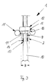
- Figure 3 shows an enlarged view of the device 1 in an operating position in which the The hose 10 is transferred from the receptacle 2 to a holder 11.
- the hose 10 at the end section 12 with its first outer surface 13 against an edge region 14 of the opening 8 in a form-fitting manner, the elastic region of the hose 10 is deformed.
- the end section 12 lies with its second, opposite the first outer surface 13 expanded outer surface 15 against an edge region 16 of a recess 17 of the bracket 11.
- the width of the receptacle 2 is such that Recess 17 of the bracket 11 matched that this from above through the recess 17th can be lowered until the end portion 12 at the edge region 16 of the recess 17 rests and is thereby stripped from the receptacle 2.
- the bracket 11 are raised. This further simplifies handling, in particular Operating errors of the device 1 can be excluded.
Landscapes
- Health & Medical Sciences (AREA)
- Public Health (AREA)
- Business, Economics & Management (AREA)
- Emergency Management (AREA)
- Supports For Pipes And Cables (AREA)
- Storing, Repeated Paying-Out, And Re-Storing Of Elongated Articles (AREA)
Abstract
Description
- Fig. 1
- eine Seitenansicht einer erfindungsgemäßen Vorrichtung;
- Fig.2
- eine Draufsicht der in Figur 1 dargestellten Vorrichtung;
- Fig.3
- eine Betriebsposition der Vorrichtung in einer vergrößerten Vorderansicht.
Claims (14)
- Vorrichtung (1) zum vorübergehenden Aufhängen von Schläuchen (10) mit einer Aufnahme (2), mittels der die Schläuche (10) angehoben und mit ihrem erweiterten Endabschnitt (12) in einer Halterung (11) derart abgelegt werden können, daß der jeweilige Schlauch (10) im wesentlichen frei herabhängt, dadurch gekennzeichnet, daß die Aufnahme (2) eine zumindest entsprechend der doppelten Wandstärke des Schlauches (10) bemessene Durchbrechung (8) aufweist, gegen deren Randbereich (14) der Endabschnitt (12) des Schlauches (10) mit einer ersten Außenfläche (13) anlegbar ist und daß die Halterung (11) eine Aussparung (17) für eine von der ersten Außenfläche (13) abweichende zweite Außenfläche (15) des Schlauches (10) aufweist.
- Vorrichtung (1) nach Anspruch 1, dadurch gekennzeichnet, daß die zweite Außenfläche (15) von einer Längsachse des Schlauches (10) einen wesentlich größeren Abstand als die erste Außenfläche (13) aufweist.
- Vorrichtung (1) nach den Ansprüchen 1 oder 2, dadurch gekennzeichnet, daß die Aufnahme (2) eine geringere Breite (B) als die Aussparung (17) der Halterung (11) aufweist.
- Vorrichtung (1) nach zumindest einem der vorhergehenden Ansprüche, dadurch gekennzeichnet, daß die Aufnahme (2) eine Gabel mit einer Einführhilfe (9) für den Schlauch (10) aufweist.
- Vorrichtung (1) nach zumindest einem der vorhergehenden Ansprüche, dadurch gekennzeichnet, daß die Durchbrechung (8) der Aufnahme (2) derart bemessen ist, daß zwischen den Wandflächen des fixierten Schlauches (10) ein lediglich geringer Zwischenraum verbleibt.
- Vorrichtung (1) nach zumindest einem der vorhergehenden Ansprüche, dadurch gekennzeichnet, daß die Aufnahme (2) für zwei Endabschnitte (12) desselben Schlauches (10) bemessen ist.
- Vorrichtung (1) nach zumindest einem der vorhergehenden Ansprüche, dadurch gekennzeichnet, daß die Aufnahme (2) für Endabschnitte (12) mehrerer Schläuche (10) bemessen ist.
- Vorrichtung (1) nach zumindest einem der vorhergehenden Ansprüche, dadurch gekennzeichnet, daß die Aufnahme (2) mit einem Fördermittel der Vorrichtung (1) dauerhaft verbunden ist.
- Vorrichtung (1) nach zumindest einem der vorhergehenden Ansprüche, dadurch gekennzeichnet, daß die Vorrichtung (1) eine Positionierungshilfe (5) für die relative Lage der Aufnahme (2) gegenüber der Halterung (11) aufweist.
- Vorrichtung (1) nach Anspruch 9, dadurch gekennzeichnet, daß die Positionierungshilfe (5) eine Zentrierung bezüglich der Hubachse der Vorrichtung (1) aufweist.
- Vorrichtung (1) nach zumindest einem der vorhergehenden Ansprüche, dadurch gekennzeichnet, daß der Endabschnitt (12) des Schlauches in die Durchbrechung (8) der Aufnahme (2) automatisiert einführbar ist.
- Vorrichtung (1) nach zumindest einem der vorhergehenden Ansprüche, dadurch gekennzeichnet, daß die Vorrichtung (1) eine Wickeleinrichtung für den Schlauch (10) aufweist.
- Vorrichtung (1) nach zumindest einem der vorhergehenden Ansprüche, dadurch gekennzeichnet, daß mittels einer Steuereinheit der Vorrichtung (1) beim Absenken des Schlauches (10) die geometrische Mitte des Schlauches (10) bestimmbar ist.
- Vorrichtung (1) nach zumindest einem der vorhergehenden Ansprüche, dadurch gekennzeichnet, daß die Vorrichtung (1) eine Übergabestation aufweist, mittels der die Aufnahme (2) und die Halterung (11) in einer insbesondere horizontalen Ebene relativ zueinander beweglich sind.
Applications Claiming Priority (2)
| Application Number | Priority Date | Filing Date | Title |
|---|---|---|---|
| DE2001128560 DE10128560C1 (de) | 2001-06-14 | 2001-06-14 | Vorrichtung zum Aufhängen von Schläuchen |
| DE10128560 | 2001-06-14 |
Publications (1)
| Publication Number | Publication Date |
|---|---|
| EP1266675A1 true EP1266675A1 (de) | 2002-12-18 |
Family
ID=7688087
Family Applications (1)
| Application Number | Title | Priority Date | Filing Date |
|---|---|---|---|
| EP02013024A Withdrawn EP1266675A1 (de) | 2001-06-14 | 2002-06-13 | Vorrichtung zum Aufhängen von Schläuchen |
Country Status (2)
| Country | Link |
|---|---|
| EP (1) | EP1266675A1 (de) |
| DE (1) | DE10128560C1 (de) |
Citations (7)
| Publication number | Priority date | Publication date | Assignee | Title |
|---|---|---|---|---|
| DE1089269B (de) * | 1953-09-07 | 1960-09-15 | Siegfried Dornbusch | Vorrichtung zum Aufhaengen von Schlaeuchen in einem Trockenturm |
| DE1227344B (de) * | 1959-07-31 | 1966-10-20 | Albert Ziegler Fa | Vorrichtung zum Aufhaengen von Schlaeuchen in einem Trockenturm |
| DE1531206A1 (de) | 1967-12-27 | 1970-01-22 | H Huetter Jun Fa | Vorrichtung zum Aufhaengen von zu trocknenden Schlaeuchen |
| DE1708073A1 (de) | 1967-04-22 | 1970-07-02 | Albert Mahr | Trockenvorrichtung fuer Feuerwehrschlaeuche |
| DE2207023A1 (de) | 1972-02-15 | 1973-08-23 | Jun Leonhard Sturz | Vorrichtung zum aufhaengen von feuerloeschschlaeuchen in trockentuermen |
| DE3708591A1 (de) | 1986-03-17 | 1987-09-24 | Rud Prey Kiel Fabrik Fuer Aufz | Vorrichtung zum aufhaengen von schlaeuchen in einem trockenturm |
| EP0397461A1 (de) * | 1989-05-12 | 1990-11-14 | Chubb Fire Limited | Schlauchaufrollapparat |
Family Cites Families (1)
| Publication number | Priority date | Publication date | Assignee | Title |
|---|---|---|---|---|
| DE7623096U1 (de) * | 1976-07-22 | 1978-02-23 | Gecos Maschinen- U. Apparatebau Gmbh, 4800 Bielefeld | Vorrichtung zum aufhaengen von schlaeuchen in einem turm |
-
2001
- 2001-06-14 DE DE2001128560 patent/DE10128560C1/de not_active Expired - Fee Related
-
2002
- 2002-06-13 EP EP02013024A patent/EP1266675A1/de not_active Withdrawn
Patent Citations (7)
| Publication number | Priority date | Publication date | Assignee | Title |
|---|---|---|---|---|
| DE1089269B (de) * | 1953-09-07 | 1960-09-15 | Siegfried Dornbusch | Vorrichtung zum Aufhaengen von Schlaeuchen in einem Trockenturm |
| DE1227344B (de) * | 1959-07-31 | 1966-10-20 | Albert Ziegler Fa | Vorrichtung zum Aufhaengen von Schlaeuchen in einem Trockenturm |
| DE1708073A1 (de) | 1967-04-22 | 1970-07-02 | Albert Mahr | Trockenvorrichtung fuer Feuerwehrschlaeuche |
| DE1531206A1 (de) | 1967-12-27 | 1970-01-22 | H Huetter Jun Fa | Vorrichtung zum Aufhaengen von zu trocknenden Schlaeuchen |
| DE2207023A1 (de) | 1972-02-15 | 1973-08-23 | Jun Leonhard Sturz | Vorrichtung zum aufhaengen von feuerloeschschlaeuchen in trockentuermen |
| DE3708591A1 (de) | 1986-03-17 | 1987-09-24 | Rud Prey Kiel Fabrik Fuer Aufz | Vorrichtung zum aufhaengen von schlaeuchen in einem trockenturm |
| EP0397461A1 (de) * | 1989-05-12 | 1990-11-14 | Chubb Fire Limited | Schlauchaufrollapparat |
Also Published As
| Publication number | Publication date |
|---|---|
| DE10128560C1 (de) | 2003-05-08 |
Similar Documents
| Publication | Publication Date | Title |
|---|---|---|
| EP0386339B1 (de) | Vorrichtung zur Übergabe von Einzelspulen oder Spulengruppen an eine Spulentransporteinrichtung | |
| EP0714771B1 (de) | Verfahren und Vorrichtung zur Bereitstellung einer Druckplatte | |
| DE3000723C2 (de) | Verfahren und Vorrichtung zum kontinuierlichen Zuführen von Papierbobinen zu einer Maschine der tabakverarbeitenden Industrie | |
| EP2657380A2 (de) | Verfahren und Vorrichtung zum Betreiben von Arbeitsstellen einer Offenend-Rotorspinnmaschine | |
| DE2833955C2 (de) | Einzelspuler zum Aufwickeln von Stranggut, insbesondere von Draht | |
| DE4132998C2 (de) | Ansaug- und Transportvorrichtung | |
| DE3912127C2 (de) | ||
| DE19813698A1 (de) | Bohrgestängemagazin | |
| EP0380930A1 (de) | Hängefördersystem | |
| DE69707395T2 (de) | Verbesserter Transportwagen zum Halten der Spulen und Spulenhülsen in einer aufrechten Position zum Transport und zur Positionierung in Textilmaschinen | |
| DE3825273C2 (de) | Spulentransporteinrichtung mit auskragendem Dorn | |
| EP0392175B1 (de) | Vorgarnspulenwechselwagen | |
| EP1266675A1 (de) | Vorrichtung zum Aufhängen von Schläuchen | |
| DE3626805C2 (de) | Hubeinrichtung | |
| EP0503016B1 (de) | Vorrichtung zum automatischen handhaben von spulenhülsen und fertiggewickelten spulen von spinnmaschinen | |
| EP0178458A2 (de) | Wickelvorrichtung | |
| EP0628648A2 (de) | Vorrichtung zum Bestücken der Spulendorne eines Spulengatters | |
| EP0737642A2 (de) | Kräuselmaschine | |
| DE4102468C2 (de) | ||
| EP0216950B1 (de) | Trageinrichtung für ein Hängetransportsystem | |
| DE102007008721A1 (de) | Automatischer Anleger | |
| DE3039202C2 (de) | ||
| DE3840090A1 (de) | Vorrichtung zum einlegen von konischen leerhuelsen in die spulvorrichtung einer textilmaschine | |
| WO2020234120A1 (de) | Radhalter | |
| AT500419B1 (de) | Vorrichtung zum aufhängen von feuerwehrschläuchen |
Legal Events
| Date | Code | Title | Description |
|---|---|---|---|
| PUAI | Public reference made under article 153(3) epc to a published international application that has entered the european phase |
Free format text: ORIGINAL CODE: 0009012 |
|
| AK | Designated contracting states |
Kind code of ref document: A1 Designated state(s): AT BE CH CY DE DK ES FI FR GB GR IE IT LI LU MC NL PT SE TR |
|
| AX | Request for extension of the european patent |
Free format text: AL;LT;LV;MK;RO;SI |
|
| 17P | Request for examination filed |
Effective date: 20030407 |
|
| AKX | Designation fees paid |
Designated state(s): AT ES FR IT |
|
| REG | Reference to a national code |
Ref country code: DE Ref legal event code: 8566 |
|
| 17Q | First examination report despatched |
Effective date: 20071106 |
|
| GRAP | Despatch of communication of intention to grant a patent |
Free format text: ORIGINAL CODE: EPIDOSNIGR1 |
|
| STAA | Information on the status of an ep patent application or granted ep patent |
Free format text: STATUS: THE APPLICATION IS DEEMED TO BE WITHDRAWN |
|
| 18D | Application deemed to be withdrawn |
Effective date: 20081028 |