EP1264772A2 - Etikettiervorrichtung für CDs - Google Patents
Etikettiervorrichtung für CDs Download PDFInfo
- Publication number
- EP1264772A2 EP1264772A2 EP02001695A EP02001695A EP1264772A2 EP 1264772 A2 EP1264772 A2 EP 1264772A2 EP 02001695 A EP02001695 A EP 02001695A EP 02001695 A EP02001695 A EP 02001695A EP 1264772 A2 EP1264772 A2 EP 1264772A2
- Authority
- EP
- European Patent Office
- Prior art keywords
- flexible material
- flat object
- material sheet
- layer
- composite
- Prior art date
- Legal status (The legal status is an assumption and is not a legal conclusion. Google has not performed a legal analysis and makes no representation as to the accuracy of the status listed.)
- Granted
Links
Images


Classifications
-
- B—PERFORMING OPERATIONS; TRANSPORTING
- B65—CONVEYING; PACKING; STORING; HANDLING THIN OR FILAMENTARY MATERIAL
- B65C—LABELLING OR TAGGING MACHINES, APPARATUS, OR PROCESSES
- B65C9/00—Details of labelling machines or apparatus
- B65C9/26—Devices for applying labels
- B65C9/262—Devices for applying labels manually operable
- B65C9/265—Devices for applying labels manually operable specially adapted for compact discs
Definitions
- the invention relates to a system for applying a flexible sheet of material on a flat object.
- CD's For storing information of all kinds, such as music and other data, so-called CD's are used can be written once or repeatedly. For identification these CDs become labels that can be written on glued.
- the recorded CD is in the CD case inserted, with the side to be glued facing shows above. Then a centering aid is opened put the central wreath on.
- the adhesive label shows a central, circular cut-out that the The size of the centering aid corresponds. The adhesive label is then with this central punch over the centering aid led and pressed.
- This system has however, the disadvantage that it is a lot of practice and a lot A steady hand is required to make the adhesive label as precise as possible centered.
- DE 298 00 751 therefore describes an arrangement for application described a label on a CD-ROM, the consists of a composite consisting of at least one Carrier layer and a wear layer is formed, wherein the label through a punched-out part of the wear layer is formed and wherein an edge region of the Compound forms an investment aid outside of the label.
- the carrier layer is formed in two parts, so that to apply the label a first part of the Carrier material is pulled off the label, so that a Part of the adhesive surface of the label has already been released and the other part of the adhesive surface is still covered. Then the label with the investment aid in inserted the CD case, the investment aid on three Sides comes into contact with the CD case and thereby aligns the network.
- the label is then with the the previously exposed adhesive surface is pressed onto the CD, then the covered part of the label folded and the rest of the backing material together removed with the investment aid.
- the label can then be completely glued to the CD.
- the invention is therefore based on the object of a system to apply a flexible sheet of material specify a flat object that is simple to handle and a precisely fitting application enables.
- the first means of alignment are by at least a die cut and the second means for alignment by at least one complementary Elevation formed, the association with the punching can be suspended in the elevation of the device in this way is that between assembly and device an immovable Fit is created.
- the first Alignment means by two spaced preferably circular register punchings and the second Funded by two surveys, particularly two appropriately complementary cones formed.
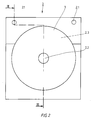
- 1 to 3 is a first embodiment a system for applying a flexible sheet of material 10.1 shown on a flat object 3. It consists of a composite 1, at least a carrier layer 10 and a wear layer 11 has, and a device 2 for applying the flexible material sheet 10.1 on the flat object 3.
- the flexible material sheet 10.1 is through formed a punched-out part of the wear layer 10, and in an edge area of the composite 1 are outside of the flexible material sheet 10.1 first means, in particular Punch holes 1.1, for aligning the flexible Sheet of material related to the flat object intended.
- the flexible material sheet serves as an embodiment 10.1 as a label for a CD.
- the flexible material sheet 10.1 is by punching lines 10.2 and 10.3 in the wear layer 10 is punched out.
- the flexible material sheet 10.1 and the remaining part of the wear layer 10 are held together by being on the support layer 11 stick.
- the wear layer 10 and thus also the flexible material sheet 10.1 self-adhesive.
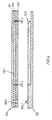
- the device 2 shown in FIGS. 2 and 3 to apply the flexible material sheet 10.1 the flat object 3 has a means 2.2 to fix the flat object 3 and second Means for aligning the flexible material sheet 10.1 with respect to the flat object 3.
- This second means are here through surveys, in particular Pins 2.1 formed, which are correspondingly complementary to the punched holes 1.1 of the composite 1 are.
- the distance between the two pins 2.1 corresponds the distance between the punched holes 1.1.
- the diameter the pin is slight, for example 1/10 mm, larger than the diameter of the register punchings.
- the composite 1 with its register punchings 1.1 hung in the pin 2.1 of the device 2 be so that between composite and device an immovable fit is created.
- the flat object 3 is formed by a CD, which in the middle is a usual circular recess has means 2.2 for fixing the CD for example formed by a centering ring, as he usually in the known CD cases is provided.
- the flat object 3 is within the scope of the invention by no means limited to a CD, but it rather, all objects are conceivable on the one flexible sheet of material could be applied. So the flat object could for example also formed by cards, printed sheets, etc. which are to be laminated with a transparent film.
- the means for fixing the flat object for example, through a corresponding recess are formed on the device 2 in the the flat object 3 is inserted.
- the device 2 has an exemplary embodiment also a recess 2.3 in which a part of the flat object 3 is added.
- the depth of the Recess 2.3 corresponds approximately to the thickness of the flat Item 3, so that the surface 2.4 of the Device 2 from which the pins 2.1 protrude upwards approximately flush with the surface of the device 2 fixed flat object 3 completes.
- Carrier layer 11 of the composite at least in two parts educated.
- the carrier layer 11 by a first part 11.1 and a second part 11.2 formed by a punch line 11.3 are separated from each other.
- the wear layer 10 is in the illustrated embodiment from the completely punched out flexible Material sheet 10.1, a first remaining part 10.4, a second remaining part 10.5 and one third remaining part 10.6, the third remaining Part 10.6 through the central circular Punching line 10.3 is formed and the first and second remaining part 10.4, 10.5 of the wear layer 10 through Punching lines 10.7 and 10.8 are separated from each other.
- both the backing layer and the remaining one Part of the wear layer is formed in two parts, can be used to apply the flexible material sheet 10.1 a partial area of the adhesive surface on the flat object 3 of the flexible material sheet 10.1 exposed be by the remaining part of the wear layer 10.5 together with the second part 11.2 of the carrier layer is separated from the rest of the network.
- the Cutting line 11.3 between the first and the second Part of the carrier layer runs such that a part of the second carrier element 11.2 also on the flexible Material sheet 10.1 is liable.
- the flat object should be labeled or printed.
- the network can do this for example using a conventional printer be printed before the flexible material sheet is applied becomes.
- this lettering or printing as possible little is rubbed off and a blurring of the Print image, for example by the action of Liquids to be avoided.
- the flexible material sheet could be used for such applications be formed by a transparent film, with which an already printed flat object is laminated can be.
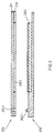
- 4 is a corresponding one Application shown.
- the device 102 for application corresponds in particular to the flexible material sheet 101 regarding the pins 102.1 of the device according to the first embodiment.
- the flat object 103 already printed and should have a transparent film 110 to be concealed.
- the flat object 103 can for example, it is a CD that already according to the first embodiment with a labeled Label has been provided. It can but can also be any printed card, which is to be protected with the transparent film.
- the composite 101 is constructed in three layers, in which case both the carrier layer 111 as well as the wear layer formed by the transparent film 110 is self-adhesive.
- the adhesive surface the wear layer 110 is then covered by a cover layer 120 covered.
- This cover layer can for example formed by a silicone masking paper become.
- the flexible material sheet 110.1 is again by a punched out along punching lines 110.2 Part of the wear layer 110 is formed. When punching out becomes the cover layer in addition to the wear layer 110 120 severed. The cohesion of the association will then ensured by the carrier layer 111.
- Punch holes 101.1 in turn work with pins 102.1 on the device 102 together, so that a precise fit Align the flexible sheet of material 110.1 with respect on the flat object 103 is guaranteed.
- the flat object 103 becomes the cover layer 120 removed at least in the area of the flexible material sheet, before the composite 101 is hooked into the pins 102.1 becomes.
- the covering layer 120 could do so are punched, as in the first embodiment along the punching line 11.3 in the carrier layer 11 has been shown. This could in turn initially only part of the cover paper from the flexible Material sheets 110.1 are removed, so that the Handling when hanging the composite in the device is facilitated. Once the flexible sheet of material 110.1 with the exposed adhesive surface on the flat Item 103 is liable, is a relative movement between both parts no longer possible, so that then easy way to remove the rest of the masking paper and the flexible material sheet completely the flat object 103 can be applied. Finally, the actual carrier layer 111 away.
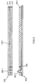
- the composite has 201 in turn a wear layer 210 and a carrier layer 211, wherein the wear layer 210 by a so-called backing film is formed, which in one commercially available printers first printed mirror-inverted becomes.
- the carrier layer 211 is self-adhesive formed, and the wear layer 210 with the punched out flexible material sheet 210.1 adheres to it Support layer.
- the flat object 203 has its to be provided with the flexible material sheet Already have an adhesive layer on the sides.
- the flat Item could be, for example, a blank card in the form of a credit card, one or both sides with an adhesive layer which is initially covered with masking paper. This blank card can then be removed by removing the cover paper for example with the printed backing film be provided.
- the special advantage of Using a backing film is that the printed part comes into contact with the adhesive surface and thus a high-gloss, protected surface arises.
- the flat object 203 only needs the compound 201 be hooked into the pin 202.1 in order to subsequently the punched out flexible material sheet 210.1 to press and close on the flat object fix.
- the embodiment of Figure 6 differs in particular by the means for fixing the flat Object. While in the previously described Embodiments of the flat object for example through a central centering ring and / or a correspondingly designed recess for Inserting the flat object has been formed is the flat object 303 in the embodiment 6 also by the pin 302.1 the device 302 fixed by the flat object in accordance with compound 301 as well Has register punchings with which the flat object 303 can be hooked into the device.
- the flat object 303 is, for example, by a conventional, printable sheet of paper or cardboard formed by a transparent film after printing should be protected.
- Compound 301 corresponds therefore from the structure of the composite 101 according to FIG. 4. Since usually the register punched on the laminated flat object 303 are perceived as disturbing, Appropriate measures can be taken to cover the area of the flat object 303, which the register punchings has to be removed after lamination. In the simplest case, this will be done by cutting off can reach this area. However, it is also conceivable, a perforation or, as shown, a narrow tape 304 to use after lamination the area with the register punchings to remove the flat object.
- the flat object is not provided with appropriate register punchings, but the flat object on a light adhesive Partial area of the device is placed, the orientation with the help of register marks on the device he follows.
- the device forms at least the device 2, 102, 202 at the same time part of a storage case for the flat Object.
- the device can be used as Insert tray designed for a conventional CD case his.
- the depth of the Recess for the CD to be inserted can be adjusted so that the top of the insert tray on which the tenon protrude flush with the surface of the CD Transition forms.
- the device for applying the flexible sheet of material can in particular also advantageously as a storage medium for the flat object (especially a CD) if the device as mentioned above, is provided with holes in which the Pin can be inserted to apply the flat sheet of material are.
- the cones can be removed again that the flat object together with the device can be stored in conventional ring folders.
- this presupposes that the distance between the holes the specified distance to the shelf in conventional Corresponds to ring folders.
Landscapes
- Credit Cards Or The Like (AREA)
- Manufacturing Optical Record Carriers (AREA)
- Making Paper Articles (AREA)
- Details Or Accessories Of Spraying Plant Or Apparatus (AREA)
- Perforating, Stamping-Out Or Severing By Means Other Than Cutting (AREA)
- Laminated Bodies (AREA)
Abstract
Description
- einem Verbund, der wenigstens eine Trägerschicht und eine Nutzschicht aufweist, wobei ein ausgestanzter Teil der Nutzschicht den flexiblen Materialbogen bildet und wobei in einem Randbereich des Verbundes außerhalb des flexiblen Materialbogens erste Mittel zum Ausrichten des flexiblen Materialbogens in bezug auf den flächigen Gegenstand vorgesehen sind,
- sowie einer Vorrichtung zum Aufbringen des flexiblen Materialbogens auf den flächigen Gegenstand, enthaltend Mittel zum Fixieren des flächigen Gegenstand sowie zweite Mittel zum Ausrichten des flexiblen Materialbogens in bezug auf den flächigen Gegenstand.
- Fig.1
- eine Aufsicht des Verbundes gemäß einem ersten Ausführungsbeispiel,
- Fig.2
- eine Aufsicht der Vorrichtung zum Aufbringen des flexiblen Materialbogens,
- Fig.3
- eine Schnittdarstellung des Systems zum Aufbringen eines flexiblen Materialbogens gemäß der Schnittlinie III-III der Figuren 1 und 2,
- Fig.4
- eine Schnittdarstellung des Systems gemäß einem zweiten Ausführungsbeispiel,
- Fig.5
- eine Schnittdarstellung des Systems gemäß einem dritten Ausführungsbeispiel und
- Fig.6
- eine Schnittdarstellung des Systems gemäß einem vierten Ausführungsbeispiel.
Claims (10)
- System zum Aufbringen eines flexiblen Materialbogens (10.1) auf einen flächigen Gegenstand (3), bestehend ausdadurch gekennzeichnet, daß die ersten Mittel zum Ausrichten durch wenigstens eine Ausstanzung und die zweiten Mittel zum Ausrichten durch wenigstens eine komplementär ausgebildete Erhebung gebildet werden, wobei der Verbund mit der Ausstanzung derart in die Erhebung der Vorrichtung einhängbar ist, daß zwischen Verbund und Vorrichtung eine unverrückbare Passung entsteht.einem Verbund (1), der wenigstens eine Trägerschicht (11) und eine Nutzschicht (10) aufweist, wobei ein ausgestanzter Teil der Nutzschicht den flexiblen Materialbogen (10.1) bildet und wobei in einem Randbereich des Verbundes (1) außerhalb des flexiblen Materialbogens erste Mittel zum Ausrichten des flexiblen Materialbogens in bezug auf den flächigen Gegenstand vorgesehen sind,sowie einer Vorrichtung (2) zum Aufbringen des flexiblen Materialbogens (10.1) auf den flächigen Gegenstand (3), enthaltend Mittel (2.2) zum Fixieren des flächigen Gegenstands sowie zweite Mittel zum Ausrichten des flexiblen Materialbogens in bezug auf den flächigen Gegenstand,
- System nach Anspruch 1, dadurch gekennzeichnet, daß die ersten Mittel zum Ausrichten durch zwei beabstandete Passerstanzungen (1.1) und die zweiten Mittel durch zwei Erhebungen gebildet werden.
- System nach Anspruch 1, dadurch gekennzeichnet, daß die ersten Mittel durch zwei kreisrunde Passerstanzungen (1.1) und die zweiten Mittel durch zwei entsprechend komplementär ausgestaltete Zapfen (2.1) gebildet werden.
- System nach Anspruch 1, dadurch gekennzeichnet, daß der flexible Materialbogen (10.1) und der verbleibende Rest der Nutzschicht (10) an der Trägerschicht (11) haften.
- System nach Anspruch 1, dadurch gekennzeichnet, daß die Trägerschicht (11) des Verbundes zweiteilig ausgebildet ist.
- System nach Anspruch 1, dadurch gekennzeichnet, daß die Trägerschicht selbstklebend ausgebildet ist.
- System nach Anspruch 1, dadurch gekennzeichnet, daß die Nutzschicht selbstklebend ausgebildet ist.
- System nach Anspruch 1, dadurch gekennzeichnet, daß der Verbund ferner eine Abdeckschicht 120 aufweist, wobei die Nutzschicht 110 zwischen Trägerschicht 111 und Abdeckschicht 120 angeordnet ist.
- System nach Anspruch 1, dadurch gekennzeichnet, daß der flexible Materialbogen durch ein beschriftbares Etikett gebildet wird.
- Vorrichtung nach einem oder mehreren der vorhergehenden Ansprüche, dadurch gekennzeichnet, daß die Erhebungen der Vorrichtung durch einsteckbare Zapfen (2.1, 102.1, 202.1) gebildet werden.
Applications Claiming Priority (2)
| Application Number | Priority Date | Filing Date | Title |
|---|---|---|---|
| DE10127256 | 2001-06-05 | ||
| DE2001127256 DE10127256C2 (de) | 2001-06-05 | 2001-06-05 | System zum Aufbringen eines flexiblen Materialbogens |
Publications (3)
| Publication Number | Publication Date |
|---|---|
| EP1264772A2 true EP1264772A2 (de) | 2002-12-11 |
| EP1264772A3 EP1264772A3 (de) | 2003-01-02 |
| EP1264772B1 EP1264772B1 (de) | 2004-07-07 |
Family
ID=7687249
Family Applications (1)
| Application Number | Title | Priority Date | Filing Date |
|---|---|---|---|
| EP20020001695 Expired - Lifetime EP1264772B1 (de) | 2001-06-05 | 2002-01-24 | Etikettiervorrichtung für CDs |
Country Status (3)
| Country | Link |
|---|---|
| EP (1) | EP1264772B1 (de) |
| DE (1) | DE10127256C2 (de) |
| ES (1) | ES2223971T3 (de) |
Cited By (5)
| Publication number | Priority date | Publication date | Assignee | Title |
|---|---|---|---|---|
| WO2004064013A2 (en) * | 2003-01-10 | 2004-07-29 | Flynn Timothy J | Label assembly and apparatus for applying a label |
| US6799621B2 (en) * | 2003-01-10 | 2004-10-05 | Timothy J. Flynn | Label assembly and apparatus |
| US6881461B2 (en) | 2003-01-10 | 2005-04-19 | Timothy J. Flynn | Indexable label assembly |
| US6932133B1 (en) | 2004-02-03 | 2005-08-23 | Timothy J. Flynn | Apparatus and method for transferring a label portion from a label assembly onto an object |
| US7001476B2 (en) | 2004-02-03 | 2006-02-21 | Flynn Timothy J | Apparatus and method for transferring a label portion from a label assembly onto an object |
Citations (1)
| Publication number | Priority date | Publication date | Assignee | Title |
|---|---|---|---|---|
| DE29800751U1 (de) | 1997-01-23 | 1998-06-18 | HERMA GmbH + Co KG, 70327 Stuttgart | Anordnung mit einem flexiblen beschriftbaren Etikettenmaterial |
Family Cites Families (6)
| Publication number | Priority date | Publication date | Assignee | Title |
|---|---|---|---|---|
| DE8306207U1 (de) * | 1983-11-03 | Georg Kohl GmbH + Co, 7129 Brackenheim | Belegkarte mit Markierungsetikett, insbesondere für Untersuchungsergebnisse in Krankenhäuser, Kliniken usw. | |
| DE2701911A1 (de) * | 1977-01-19 | 1978-07-20 | Eppendorf Geraetebau Netheler | Probengefaess sowie auf diesem zu befestigendes etikett |
| DE29617424U1 (de) * | 1996-06-05 | 1996-12-05 | Claußnitzer, Werner, 42329 Wuppertal | Vorrichtung zum Aufbringen eines Etiketts auf eine Compactdisc o.dgl. |
| CA2276359A1 (en) * | 1996-12-31 | 1998-07-09 | Andre Schwaller | Device for applying a pressure-sensitive label on a disk-shaped article |
| DE20012331U1 (de) * | 1999-07-30 | 2001-02-22 | Claußnitzer sen., Werner, 42329 Wuppertal | Adaptervorrichtung für eine CD-Etikettiervorrichtung |
| SE9903758L (sv) * | 1999-10-18 | 2001-04-19 | Thord Roenngard | Sätt att på en CD-skiva anbringa en etikett samt etikett och anordning för genomförande av sättet |
-
2001
- 2001-06-05 DE DE2001127256 patent/DE10127256C2/de not_active Expired - Fee Related
-
2002
- 2002-01-24 ES ES02001695T patent/ES2223971T3/es not_active Expired - Lifetime
- 2002-01-24 EP EP20020001695 patent/EP1264772B1/de not_active Expired - Lifetime
Patent Citations (1)
| Publication number | Priority date | Publication date | Assignee | Title |
|---|---|---|---|---|
| DE29800751U1 (de) | 1997-01-23 | 1998-06-18 | HERMA GmbH + Co KG, 70327 Stuttgart | Anordnung mit einem flexiblen beschriftbaren Etikettenmaterial |
Cited By (7)
| Publication number | Priority date | Publication date | Assignee | Title |
|---|---|---|---|---|
| WO2004064013A2 (en) * | 2003-01-10 | 2004-07-29 | Flynn Timothy J | Label assembly and apparatus for applying a label |
| US6799621B2 (en) * | 2003-01-10 | 2004-10-05 | Timothy J. Flynn | Label assembly and apparatus |
| US6881461B2 (en) | 2003-01-10 | 2005-04-19 | Timothy J. Flynn | Indexable label assembly |
| WO2004064013A3 (en) * | 2003-01-10 | 2005-09-22 | Timothy J Flynn | Label assembly and apparatus for applying a label |
| US6955843B2 (en) | 2003-01-10 | 2005-10-18 | Flynn Timothy J | Label assembly |
| US6932133B1 (en) | 2004-02-03 | 2005-08-23 | Timothy J. Flynn | Apparatus and method for transferring a label portion from a label assembly onto an object |
| US7001476B2 (en) | 2004-02-03 | 2006-02-21 | Flynn Timothy J | Apparatus and method for transferring a label portion from a label assembly onto an object |
Also Published As
| Publication number | Publication date |
|---|---|
| DE10127256A1 (de) | 2002-12-12 |
| DE10127256C2 (de) | 2003-04-24 |
| EP1264772B1 (de) | 2004-07-07 |
| EP1264772A3 (de) | 2003-01-02 |
| ES2223971T3 (es) | 2005-03-01 |
Similar Documents
| Publication | Publication Date | Title |
|---|---|---|
| DE69533877T2 (de) | Vorrichtung zum laminieren von karter | |
| EP0946936B1 (de) | Etikett zum etikettieren von vorzugsweise zylindrischen behältnissen und behältnis mit einem solchen etikett | |
| DE69408002T2 (de) | Geschäftsformular mit Identitätskarte | |
| EP1581395B1 (de) | Individualisiertes sicherheitsdokument | |
| DE60128221T2 (de) | Etikettenkonstruktion für compact discs | |
| DE29800751U1 (de) | Anordnung mit einem flexiblen beschriftbaren Etikettenmaterial | |
| DE69618073T2 (de) | Haftetikett-/Faltbroschürenaufbau | |
| EP1264772B1 (de) | Etikettiervorrichtung für CDs | |
| DE3750874T2 (de) | Teilweise ablösbares Selbstklebeetikett. | |
| DE19929679C1 (de) | Materialbahn mit Überdeckungsetikett sowie Verfahren und Vorrichtung zur Verarbeitung einer solchen Materialbahn | |
| EP1295733A1 (de) | Formblatt, sowie Verfahren zum Herstellen eines Formblattes mit integriertem RFID-Transponder | |
| DE10017141A1 (de) | Kennzeichnungsträger, Verfahren zu dessen Herstellung und Verfahren zur Kennzeichnung eines Gegenstandes | |
| DE2656021B2 (de) | Briefordner zur Aufnahme von gelochtem Schriftgut | |
| DE10227230A9 (de) | Anordnung sowie Verfahren zum zentrierten Aufbringen eines Etiketts auf einen Datenträger | |
| DE29810755U1 (de) | Kartenverbund und Vorrichtung zu seiner Herstellung | |
| EP0917123A2 (de) | Laminierbarer Markierer und Verfahren zu seiner Herstellung | |
| EP1024468B1 (de) | Etikettenbogen | |
| EP3156252B1 (de) | System zum aufbringen eines sicherheitsaufklebers auf ein objekt und entsprechendes verfahren | |
| EP0989085B1 (de) | Etikettenstreifen | |
| DE10161430C1 (de) | Anordnung sowie Verfahren zum zentrierten Aufbringen eines Etiketts auf einen Datenträger | |
| DE4017635C2 (de) | ||
| DE2802122A1 (de) | Verfahren zur herstellung von foliengeschuetzten etiketten, und klebefolie zur verwendung bei diesem verfahren | |
| DE4429198C1 (de) | Dokumentenvorlage | |
| DE9013016U1 (de) | Karte wie Kreditkarte, Clubkarte, Etikett o.dgl. | |
| DE20204913U1 (de) | Verbund |
Legal Events
| Date | Code | Title | Description |
|---|---|---|---|
| PUAI | Public reference made under article 153(3) epc to a published international application that has entered the european phase |
Free format text: ORIGINAL CODE: 0009012 |
|
| PUAL | Search report despatched |
Free format text: ORIGINAL CODE: 0009013 |
|
| AK | Designated contracting states |
Kind code of ref document: A2 Designated state(s): AT BE CH CY DE DK ES FI FR GB GR IE IT LI LU MC NL PT SE TR |
|
| AX | Request for extension of the european patent |
Free format text: AL;LT;LV;MK;RO;SI |
|
| AK | Designated contracting states |
Kind code of ref document: A3 Designated state(s): AT BE CH CY DE DK ES FI FR GB GR IE IT LI LU MC NL PT SE TR |
|
| AX | Request for extension of the european patent |
Free format text: AL;LT;LV;MK;RO;SI |
|
| 17P | Request for examination filed |
Effective date: 20030115 |
|
| GRAP | Despatch of communication of intention to grant a patent |
Free format text: ORIGINAL CODE: EPIDOSNIGR1 |
|
| AKX | Designation fees paid |
Designated state(s): CH ES FR GB IT LI PT |
|
| GRAS | Grant fee paid |
Free format text: ORIGINAL CODE: EPIDOSNIGR3 |
|
| REG | Reference to a national code |
Ref country code: DE Ref legal event code: 8566 |
|
| GRAA | (expected) grant |
Free format text: ORIGINAL CODE: 0009210 |
|
| AK | Designated contracting states |
Kind code of ref document: B1 Designated state(s): CH ES FR GB IT LI PT |
|
| PG25 | Lapsed in a contracting state [announced via postgrant information from national office to epo] |
Ref country code: IT Free format text: LAPSE BECAUSE OF FAILURE TO SUBMIT A TRANSLATION OF THE DESCRIPTION OR TO PAY THE FEE WITHIN THE PRESCRIBED TIME-LIMIT;WARNING: LAPSES OF ITALIAN PATENTS WITH EFFECTIVE DATE BEFORE 2007 MAY HAVE OCCURRED AT ANY TIME BEFORE 2007. THE CORRECT EFFECTIVE DATE MAY BE DIFFERENT FROM THE ONE RECORDED. Effective date: 20040707 Ref country code: GB Free format text: LAPSE BECAUSE OF FAILURE TO SUBMIT A TRANSLATION OF THE DESCRIPTION OR TO PAY THE FEE WITHIN THE PRESCRIBED TIME-LIMIT Effective date: 20040707 Ref country code: FR Free format text: LAPSE BECAUSE OF FAILURE TO SUBMIT A TRANSLATION OF THE DESCRIPTION OR TO PAY THE FEE WITHIN THE PRESCRIBED TIME-LIMIT Effective date: 20040707 |
|
| REG | Reference to a national code |
Ref country code: GB Ref legal event code: FG4D Free format text: NOT ENGLISH |
|
| REG | Reference to a national code |
Ref country code: CH Ref legal event code: EP |
|
| REG | Reference to a national code |
Ref country code: IE Ref legal event code: FG4D Free format text: GERMAN |
|
| GBV | Gb: ep patent (uk) treated as always having been void in accordance with gb section 77(7)/1977 [no translation filed] |
Effective date: 20040707 |
|
| PGFP | Annual fee paid to national office [announced via postgrant information from national office to epo] |
Ref country code: ES Payment date: 20050113 Year of fee payment: 4 |
|
| REG | Reference to a national code |
Ref country code: ES Ref legal event code: FG2A Ref document number: 2223971 Country of ref document: ES Kind code of ref document: T3 |
|
| REG | Reference to a national code |
Ref country code: IE Ref legal event code: FD4D |
|
| PLBE | No opposition filed within time limit |
Free format text: ORIGINAL CODE: 0009261 |
|
| STAA | Information on the status of an ep patent application or granted ep patent |
Free format text: STATUS: NO OPPOSITION FILED WITHIN TIME LIMIT |
|
| 26N | No opposition filed |
Effective date: 20050408 |
|
| EN | Fr: translation not filed | ||
| PG25 | Lapsed in a contracting state [announced via postgrant information from national office to epo] |
Ref country code: LI Free format text: LAPSE BECAUSE OF NON-PAYMENT OF DUE FEES Effective date: 20060131 Ref country code: CH Free format text: LAPSE BECAUSE OF NON-PAYMENT OF DUE FEES Effective date: 20060131 |
|
| REG | Reference to a national code |
Ref country code: CH Ref legal event code: PL |
|
| PG25 | Lapsed in a contracting state [announced via postgrant information from national office to epo] |
Ref country code: PT Free format text: LAPSE BECAUSE OF NON-PAYMENT OF DUE FEES Effective date: 20041207 |
|
| REG | Reference to a national code |
Ref country code: ES Ref legal event code: FD2A Effective date: 20070125 |
|
| PG25 | Lapsed in a contracting state [announced via postgrant information from national office to epo] |
Ref country code: ES Free format text: LAPSE BECAUSE OF NON-PAYMENT OF DUE FEES Effective date: 20070125 |