EP1295733A1 - Formblatt, sowie Verfahren zum Herstellen eines Formblattes mit integriertem RFID-Transponder - Google Patents
Formblatt, sowie Verfahren zum Herstellen eines Formblattes mit integriertem RFID-Transponder Download PDFInfo
- Publication number
- EP1295733A1 EP1295733A1 EP01122870A EP01122870A EP1295733A1 EP 1295733 A1 EP1295733 A1 EP 1295733A1 EP 01122870 A EP01122870 A EP 01122870A EP 01122870 A EP01122870 A EP 01122870A EP 1295733 A1 EP1295733 A1 EP 1295733A1
- Authority
- EP
- European Patent Office
- Prior art keywords
- sheet part
- rfid transponder
- layer
- integrated circuit
- removable
- Prior art date
- Legal status (The legal status is an assumption and is not a legal conclusion. Google has not performed a legal analysis and makes no representation as to the accuracy of the status listed.)
- Granted
Links
Images

Classifications
-
- G—PHYSICS
- G06—COMPUTING; CALCULATING OR COUNTING
- G06K—GRAPHICAL DATA READING; PRESENTATION OF DATA; RECORD CARRIERS; HANDLING RECORD CARRIERS
- G06K19/00—Record carriers for use with machines and with at least a part designed to carry digital markings
- G06K19/06—Record carriers for use with machines and with at least a part designed to carry digital markings characterised by the kind of the digital marking, e.g. shape, nature, code
- G06K19/067—Record carriers with conductive marks, printed circuits or semiconductor circuit elements, e.g. credit or identity cards also with resonating or responding marks without active components
- G06K19/07—Record carriers with conductive marks, printed circuits or semiconductor circuit elements, e.g. credit or identity cards also with resonating or responding marks without active components with integrated circuit chips
- G06K19/077—Constructional details, e.g. mounting of circuits in the carrier
- G06K19/07737—Constructional details, e.g. mounting of circuits in the carrier the record carrier consisting of two or more mechanically separable parts
- G06K19/07739—Constructional details, e.g. mounting of circuits in the carrier the record carrier consisting of two or more mechanically separable parts comprising a first part capable of functioning as a record carrier on its own and a second part being only functional as a form factor changing part, e.g. SIM cards type ID 0001, removably attached to a regular smart card form factor
-
- B—PERFORMING OPERATIONS; TRANSPORTING
- B42—BOOKBINDING; ALBUMS; FILES; SPECIAL PRINTED MATTER
- B42D—BOOKS; BOOK COVERS; LOOSE LEAVES; PRINTED MATTER CHARACTERISED BY IDENTIFICATION OR SECURITY FEATURES; PRINTED MATTER OF SPECIAL FORMAT OR STYLE NOT OTHERWISE PROVIDED FOR; DEVICES FOR USE THEREWITH AND NOT OTHERWISE PROVIDED FOR; MOVABLE-STRIP WRITING OR READING APPARATUS
- B42D5/00—Sheets united without binding to form pads or blocks
- B42D5/02—Form sets
- B42D5/023—Continuous form sets
- B42D5/027—Sheets or cards attached to a carrier strip or web
-
- G—PHYSICS
- G06—COMPUTING; CALCULATING OR COUNTING
- G06K—GRAPHICAL DATA READING; PRESENTATION OF DATA; RECORD CARRIERS; HANDLING RECORD CARRIERS
- G06K19/00—Record carriers for use with machines and with at least a part designed to carry digital markings
- G06K19/06—Record carriers for use with machines and with at least a part designed to carry digital markings characterised by the kind of the digital marking, e.g. shape, nature, code
- G06K19/067—Record carriers with conductive marks, printed circuits or semiconductor circuit elements, e.g. credit or identity cards also with resonating or responding marks without active components
- G06K19/07—Record carriers with conductive marks, printed circuits or semiconductor circuit elements, e.g. credit or identity cards also with resonating or responding marks without active components with integrated circuit chips
- G06K19/077—Constructional details, e.g. mounting of circuits in the carrier
- G06K19/07749—Constructional details, e.g. mounting of circuits in the carrier the record carrier being capable of non-contact communication, e.g. constructional details of the antenna of a non-contact smart card
Definitions
- the invention relates to a form according to the preamble of claim 1, and a method for producing a form with an integrated RFID transponder.
- Forms with a detachable leaf part are known.
- such removable sheet parts to create membership cards, which are separated from a letterhead, preferably an A4 letterhead can be and which are automatically produced on a printing press can.
- a particular advantage is that such letterheads with an individual Content, e.g. with a customer-specific salutation and with customer-specific Data can be provided.
- a punching is provided, which consists of an uninterrupted Cut exists or can have a cut with webs.
- this can be on its front and back be reinforced with a film that is glued to the form and over the Extends the area of the detachable leaf part. The die cut is then through all layers passed.
- RFID transponders are also known which have a flat, transparent carrier material have, on which an antenna is attached, and one with the antenna connected, integrated circuit. Such a transponder is extremely flat. On Such RFID transponders are described, for example, in DE 109 05 886 A. In conjunction with an interrogation device, the transponder serves as an identification element, that allows a direct exchange of information, while it no visual contact for the transmission of information between an interrogator and the transponder is required. The information content in the integrated The circuit of the RFID transponder can be changed if necessary.
- the integrated circuits of the known RFID transponders have a certain one Thickness so that it, applied to sheets of paper, not from finishing machines after printing could be processed without the built-in Destroy circuit.
- the invention has for its object a form and a method for Manufacturing a form with an integrated RFID transponder to create that from a processing machine without destroying the in a transponder integrated circuit can be processed.
- the invention advantageously provides that the removable sheet part an RFID transponder with an integrated circuit and an antenna carries, the detachable leaf part has a hole in which the integrated Circuit is arranged.
- the integrated circuit can, depending on the thickness of the Form be completely sunk in the hole or only slightly relative to protrude the form so that the form on a processing machine processed after printing using the adjustable gap widths and can be printed.
- the fact that the integrated circuit in the Hole sunk is reliably prevented from damage of the RFID transponder can occur even if the integrated circuit protrudes, since the thickness of the integrated circuit does not match the thickness of the form added. There is thus the possibility of changing the form individually Print information such as customer data and also corresponding or assigned electronic information in the integrated To save the circuit of the RFID transponder.
- the detachable Sheet part can be pre-punched in credit card format, so that the sheet part with the RFID transponder can be removed.
- a leaf part in Credit card format can, for example, be used as an ID for access control become.
- the sheet part is also suitable, in the form of stickers or labels To label products, e.g. for warehouse management, theft protection or for product tracking during manufacturing.
- the RFID transponder can be arranged on a carrier layer on the Front or back is attached to the leaf part.
- the attachment can done with an adhesive layer.
- the RFID transponder is preferably between the carrier layer and the Sheet part or the adhesive layer arranged.
- At least one Protective layer and / or the carrier layer of the RFID transponder made of a flexible, transparent film.
- a flexible film can already during the manufacture of the form are applied, and can also be printed if necessary become.
- the carrier layer and / or the at least one protective layer are at least partially glued to the removable leaf part.
- the protective layer can consist of an inflexible plastic layer consist.
- an inflexible plastic layer can after Apply the transponder to the sheet part and after printing on the form be applied.
- the transparent or non-transparent carrier layer is preferably for the RFID transponder glued to the removable sheet part using a layer of glue.
- the protective layer made of a flexible film is also covered with a layer of glue Side of the RFID transponder with the carrier layer or the RFID transponder even glued.
- the leaf part is separable due to a dividing line through the leaf part and punched through all other layers.
- the form is preferably made of paper, but can also be made of other printable ones film-like materials exist.
- an outer layer covering the sheet part can be used Silicone release paper layer may be arranged that is not from the die cut is penetrated for the detachable leaf part.
- An adhesive layer can be provided on the back of the separable sheet part whose help is the removable sheet part with the integrated RFID transponder as Stickers can be used.
- a method for producing a form with an integrated RFID transponder the form is first fed and a hole in a later stamped sheet part of the form that can be removed. Then the RFID transponder fed with an antenna and an integrated circuit and so positioned that the integrated circuit in the hole of the detachable Leaf part is arranged sunk. The RFID transponder is simultaneously e.g. fixed by gluing on the removable sheet part. Eventually one will Separation line punched for the removable sheet part.
- the front and / or back of the form with the removable sheet part can be changed before, after or during punching the hole with changeable, e.g. individualized Information to be printed.
- changeable e.g. individualized Information to be printed.
- the front and / or Back of the form even after the RFID transponder has been attached on the sheet part or after punching the dividing line for the detachable Sheet part can be printed with changeable information.
- In the Processing machine is using an inkjet or laser printer printed.
- Print information can be associated with this printed information or corresponding electronic data in the integrated circuit of the RFID transponder get saved.
- a punching tool is used to punch the dividing line Hole has a recess, so that by the punching process for the dividing line Damage to the integrated circuit can be excluded.
- Form 1 consists, for example, of a printing paper sheet or continuous paper sheet with a front 1a and a back 1b, as it is for example in A4 format or in other formats for printed matter.
- the Form 1 has a separable area 7, which with the help of a dividing line 16, which can be interrupted by webs 12 or runs continuously, separated can be.
- a dividing line 16 which can be interrupted by webs 12 or runs continuously, separated can be.
- the punching line runs through all the layers shown. But it can also not be continuous if, for example, on the back 1b of the form 1 a silicone release paper layer is arranged as the outer layer.
- the removable Sheet part 7 On the back 1b of the form 1 is on the removable Sheet part 7 an RFID transponder with an antenna 10 and one integrated circuit 6 arranged.
- the RFID transponder is supported by a carrier film 22 worn with the help of a glue layer 5 on the detachable Sheet part 7 is glued.
- the carrier film 22 can of course also be made of non-transparent Material. Furthermore, the carrier film 22 can be printed his.
- a protective layer can be applied to both the front 1a and the back 1b 4a or 4b can be provided, which covers the detachable area 7.
- This protective layer 4a, 4b also preferably consists of a flexible transparent Foil, which is why, for example, in the illustration according to FIG. 2, the RFID transponder is visible.
- the protective layer 4a, 4b can also consist of a non-transparent and possibly printable material.
- FIG. 2 shows the protective layer 4b and a carrier layer 22 of the RFID transponder transparent so that the antenna 10 and the integrated circuit 8 of the RFID transponder are visible.
- the antenna 10 and the integrated circuit on the back of the form 1 1b facing Side of the flexible transparent support layer 22 attached.
- the antenna 10 is connected to the integrated circuit 8 via two connecting lines 18, 20.
- the integrated circuit 6 is on the removable Sheet part 7 of the form 1 arranged sunk in the region of a hole 6, as on best emerges from Fig. 1.
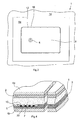
- Fig. 1 the layer structure of the detachable sheet part 7 is shown in detail.
- the following layer structure results from the back of the form:
- the back protective layer 4b is over a glue layer 3, which is separate can be applied or on the side facing the form 1
- Protective layer 4b is located with the back 1b of the form or within the Area of the detachable sheet part 7 with the back of the carrier layer 22 for the RFID transponder or connected to the back 1b of the form 1.
- the carrier layer 22, which preferably consists of a flexible transparent film, can in turn with a layer of glue 5 on the form 1 facing Be provided or with the help of a separately applied layer of glue 5 with be glued to the back of the detachable sheet part 7.
- the glue layer 5 covers the antenna 10, which on the carrier layer 22, e.g. by welding, is firmly connected. Part of the glue layer 5 penetrates when the RFID transponders in hole 6 in the removable sheet part.
- the integrated Circuit 8 is sunk in the hole 6 so that it faces the front of the form does not survive or survives only slightly.
- a protective layer 4a preferably made of a flexible, transparent film, provided with the form 1 via a glue layer 2 or is connected to the detachable sheet part 7 of the form 1.
- FIG. 4 An enlarged representation of the layer structure is shown in FIG. 4.
- Fig. 3 shows the front 1a of the form 1 in the area of the removable Sheet part 7.
- the protective layers 4a, 4b also others or additional layers can be provided, such as a silicone release paper layer, not from the die cut for the detachable sheet part is penetrated, and with the help of which it is possible to remove the leaf part 7 using the glue layer 3 as a label on a desired location of an object to stick.
- the punching tool for producing the dividing line 16 points in the area of the punched out Hole 6 a hole corresponding to the hole, so that the Die cut of the integrated circuit 8 cannot be damaged.
- the dividing line 16 can be continuous or interrupted by webs 12, as in the Embodiment of FIGS. 1 to 4 shown.
- the protective layers 4a, 4b and the corresponding glue layers 2 and 3 can also be printed on the front and back of the form 1 and after the RFID transponder has been applied, an inflexible plastic layer be applied to at least one side of the form 1.
- an inflexible plastic layer be applied to at least one side of the form 1.
- the detachable sheet part 7 can be provided with a stiffness such as that is known from current credit cards.
- the detachable sheet part 7 preferably has the usual credit card format on.
- the form with integrated RFID transponder is produced in the following Wise:
- a sheet that may already have been printed or an endless form fed to a further processing machine, being at a suitable location within a hole 6 is punched out of a later removable sheet part 7.
- a later removable sheet part 7 there can also be subsequently printed on the front and / or back 1a, 1b of the form 1 with a non-contact printer.
- the second step is the RFID transponder on a carrier layer 22, for example fed from a roll that is self-adhesive (glue layer 5) coated can.
- the functionality of the RFID transponder can also be checked in this step checked so that faulty RFID transponders are outsourced and therefore only technically perfect RFID transponders on the front or Back side 1a, 1b of the form 1 glued onto the detachable sheet part 7 become.
- the RFID transponder is positioned so that the integrated circuit 8 sunk in the hole 6 of the detachable sheet part 7 of the form 1 can be.
- the RFID transponders are located on a paper carrier that is rolled up into a roll is.
- the RFID transponders can be transverse to the transport direction of the form 1 are supplied, first of all a silicone release paper is removed and the individual RFID transponders by cutting with one Knives are separated and positioned on the form 1 in the desired manner become.
- the RFID transponders are also supplied Direction of transport of form 1 possible if the RFID transponder is appropriate are positioned on the carrier roll.
- the form 1 on its front and / or back 1a, 1b or the carrier film 22 is still possible.
- another layer of paper can finally be added be glued on.
- the removable one is punched out Sheet part 7 in a desired format, e.g. in credit card format.
- the RFID transponder can function again be checked.
- printed individualized data can be used for this data to be stored in the integrated circuit 8 from a computer memory read out and save in the RFID transponder.
Abstract
Description
- Fig. 1
- einen Schnitt durch das Formblatt entlang der Linie I-I in Fig. 2,
- Fig. 2
- eine Draufsicht auf die Rückseite des Formblatts,
- Fig. 3
- eine Ansicht der Vorderseite des Formblatts, und
- Fig. 4
- eine vergrößerte Darstellung des Querschnitts des Formblatts gemäß dem Detail IV in Fig. 1.
Claims (21)
- Formblatt (1) mit Vorder- und Rückseite (1a,1b) und einem heraustrennbaren Blattteil (7), wobei das Formblatt (1) zumindest einseitig bedruckbar ist,
dadurch gekennzeichnet, dass das heraustrennbare Blattteil (7) einen RFID-Transponder mit einem integrierten Schaltkreis (8) und einer Antenne (10) trägt, und
dass das heraustrennbare Blattteil (7) ein Loch (6) aufweist, in dem der integrierte Schaltkreis (8) angeordnet ist. - Formblatt nach Anspruch 1, dadurch gekennzeichnet, dass der RFID-Transponder auf einer Trägerschicht (22) angeordnet ist, die auf der Vorder- oder Rückseite (1a,1b) auf dem Blattteil (7) befestigt ist.
- Formblatt nach Anspruch 2, dadurch gekennzeichnet, dass der RFID-Transponder zwischen Trägerschicht (22) und dem Blattteil (7) angeordnet ist.
- Formblatt nach einem der Ansprüche 1 bis 3, dadurch gekennzeichnet, dass auf der Vorder- und/oder Rückseite (1a,1) des Formblatts (1) eine das heraustrennbare Blattteil überdeckende Schutzschicht (4a,4b) angeordnet ist.
- Formblatt nach Anspruch 4, dadurch gekennzeichnet, dass die Schutzschicht (4a,4b) aus einer unflexiblen Kunststoffschicht besteht.
- Formblatt nach Anspruch 4, dadurch gekennzeichnet, dass mindestens eine Schutzschicht (4a,4b) und/oder die Trägerschicht (22) des RFID-Transponders aus einer flexiblen, transparenten Folie besteht.
- Formblatt nach einem der Ansprüche 2 bis 6, dadurch gekennzeichnet, dass die Trägerschicht (22) und/oder die mindestens eine Schutzschicht (4a,4b) zumindest teilweise mit dem heraustrennbaren Blattteil (7) verklebt sind.
- Formblatt nach einem der Ansprüche 2 bis 7, dadurch gekennzeichnet, dass die transparente oder nicht transparente Trägerschicht (22) für den RFID-Transponder über eine Leimschicht (5) mit dem heraustrennbaren Blattteil (7) verklebt ist.
- Formblatt nach einem der Ansprüche 6 bis 8, dadurch gekennzeichnet, dass die Schutzschicht (4a,4b) über eine Leimschicht (2,3) mit dem heraustrennbaren Blattteil (7), bzw. mit der Trägerschicht (22) oder dem RFID-Transponder verklebt ist.
- Formblatt nach einem der Ansprüche 1 bis 9, dadurch gekennzeichnet, dass das Blattteil (7) aufgrund einer Trennlinie (16) heraustrennbar ist, die durch das Blattteil (7) und alle anderen Schichten hindurchgestanzt ist.
- Formblatt nach Anspruch 10, dadurch gekennzeichnet, dass die Trennlinie (16) von Stegen (12), die das Formblatt (1) mit dem heraustrennbaren Blattteil (7) verbinden, unterbrochen ist.
- Formblatt nach einem der Ansprüche 1 bis 10, dadurch gekennzeichnet, dass das Formblatt (1) aus Papier besteht.
- Formblatt nach einem der Ansprüche 1 bis 12, dadurch gekennzeichnet, dass auf der Rückseite (1b) des Formblattes (1) als äußere Schicht eine das Blattteil (7) überdeckende Silikontrennpapierschicht angeordnet ist, die nicht von dem Stanzschnitt für das heraustrennbare Blattteil (7) durchdrungen ist.
- Verfahren zum Herstellen eines mit einem RFID-Transponders versehenen Formblattes (1) mit Vorder- und Rückseite (1a,1b),durch Zuführen des Formblattes (1),durch Stanzen eines Lochs (6) in einem heraustrennbaren Blattteil (7) des Formblattes (1),durch Zuführen des RFID-Transponders mit einer Antenne (10) und einem integrierten Schaltkreis (8),durch Positionieren des integrierten Schaltkreises (8) in dem Loch (6) des heraustrennbaren Blattteils (7),durch Fixieren des RFID-Transponders auf dem heraustrennbaren Blattteil (7), unddurch Stanzen einer Trennlinie (16) für das heraustrennbare Blattteil (7).
- Verfahren nach Anspruch 14, dadurch gekennzeichnet, dass die Vorderund/oder Rückseite (1a,1b) das Formblattes (1) mit dem heraustrennbaren Blattteil (7) vor, nach oder während des Stanzens des Lochs (6) mit veränderbaren Informationen bedruckt wird.
- Verfahren nach Anspruch 14 oder 15, dadurch gekennzeichnet, dass mehrere RFID-Transponder auf einer Trägerschicht (22) fortlaufend oder intermittierend zugeführt werden und durch einen Schnitt vereinzelt auf dem heraustrennbaren Blattteil (7) des Formblattes (1) mit der Trägerschicht (22) fixiert werden.
- Verfahren nach einem der Ansprüche 14 bis 16, dadurch gekennzeichnet, dass die Vorder- und/oder Rückseite (1a,1b) des Formblatts (1) mit dem heraustrennbaren Blattteil (7) nach dem Befestigen des RFID-Transponders auf dem Blattteil (7) oder nach dem Stanzen der Trennlinie (16) für das heraustrennbare Blattteil (7) mit veränderbaren Informationen bedruckt wird.
- Verfahren nach einem der Ansprüche 14 bis 17, dadurch gekennzeichnet, dass zum Stanzen der Trennlinie (12) ein Stanzwerkzeug verwendet wird, das im Bereich des Lochs (6) eine Aussparung aufweist.
- Verfahren nach einem der Ansprüche 15 bis 18, dadurch gekennzeichnet, dass individuelle, z.B. kundenspezifische Druckinformationen und Daten auf das Formblatt (1) nachträglich durch einen Tintenstrahl- oder Laserdrucker aufgedruckt werden und dass diesen Druckinformationen und Daten zugeordnete elektronische Daten in dem integrierten Schaltkreis (8) gespeichert werden.
- Verfahren nach einem der Ansprüche 15 bis 18, dadurch gekennzeichnet, dass bereits auf dem Formblatt (1) aufgedruckte individuelle Druckinformationen und Daten dazu verwendet werden, um diesen zugeordnete elektronische Daten aus einem Rechnerspeicher auszulesen in dem integrierten Schaltkreis (8) auf dem Formblatt (1) zu speichern.
- Verfahren nach einem der Ansprüche 15 bis 18, dadurch gekennzeichnet, dass bereits zuvor in dem RFID-Transponder gespeicherte Daten ausgelesen werden, um diesen zugeordnete individuelle Druckinformationen und Daten auf das Formblatt (1) nachträglich aufzudrucken.
Priority Applications (3)
| Application Number | Priority Date | Filing Date | Title |
|---|---|---|---|
| DE50106587T DE50106587D1 (de) | 2001-09-24 | 2001-09-24 | Formblatt, sowie Verfahren zum Herstellen eines Formblattes mit integriertem RFID-Transponder |
| EP01122870A EP1295733B1 (de) | 2001-09-24 | 2001-09-24 | Formblatt, sowie Verfahren zum Herstellen eines Formblattes mit integriertem RFID-Transponder |
| AT01122870T ATE298286T1 (de) | 2001-09-24 | 2001-09-24 | Formblatt, sowie verfahren zum herstellen eines formblattes mit integriertem rfid-transponder |
Applications Claiming Priority (1)
| Application Number | Priority Date | Filing Date | Title |
|---|---|---|---|
| EP01122870A EP1295733B1 (de) | 2001-09-24 | 2001-09-24 | Formblatt, sowie Verfahren zum Herstellen eines Formblattes mit integriertem RFID-Transponder |
Publications (2)
| Publication Number | Publication Date |
|---|---|
| EP1295733A1 true EP1295733A1 (de) | 2003-03-26 |
| EP1295733B1 EP1295733B1 (de) | 2005-06-22 |
Family
ID=8178711
Family Applications (1)
| Application Number | Title | Priority Date | Filing Date |
|---|---|---|---|
| EP01122870A Revoked EP1295733B1 (de) | 2001-09-24 | 2001-09-24 | Formblatt, sowie Verfahren zum Herstellen eines Formblattes mit integriertem RFID-Transponder |
Country Status (3)
| Country | Link |
|---|---|
| EP (1) | EP1295733B1 (de) |
| AT (1) | ATE298286T1 (de) |
| DE (1) | DE50106587D1 (de) |
Cited By (9)
| Publication number | Priority date | Publication date | Assignee | Title |
|---|---|---|---|---|
| WO2005009750A1 (de) * | 2003-07-29 | 2005-02-03 | Fofitec Ag | Spendematerial zur herstellung von gegenständen mit aufgeklebten karten, herstellungsverfahren dafür und verwendung davon |
| WO2005013189A2 (de) * | 2003-08-01 | 2005-02-10 | Man Roland Druckmaschinen Ag | Verfahren zur herstellung von rfid etiketten |
| DE102004019074A1 (de) * | 2004-04-20 | 2005-11-17 | Avery Dennison Corp., Pasadena | Verfahren und Steuereinheit für einen Etikettendrucker |
| NL1026275C2 (nl) * | 2004-05-26 | 2005-12-08 | Wiebe Van Der Meer Holding B V | Draagbare inrichting en werkwijze voor het gebruik daarvan. |
| EP1657667A1 (de) * | 2004-11-15 | 2006-05-17 | MF Group S.p.A. | Kontaktlose Chipkarten und Herstellungsverfahren dafür |
| WO2006081787A1 (de) * | 2005-02-02 | 2006-08-10 | Bundesdruckerei Gmbh | Passdokument |
| WO2007000407A2 (de) * | 2005-06-28 | 2007-01-04 | Mühlbauer Ag | Verfahren und vorrichtung zur herstellung von selbstklebenden rfid-transpondern |
| EP1834287A2 (de) * | 2004-12-06 | 2007-09-19 | First Data Corporation | Ausgestanzte kontaktlose transaktionskarte |
| EP2454708A2 (de) * | 2009-07-17 | 2012-05-23 | Identive Group, Inc. | Rfid-etikettenfolie |
Citations (3)
| Publication number | Priority date | Publication date | Assignee | Title |
|---|---|---|---|---|
| EP0803379A1 (de) * | 1996-04-22 | 1997-10-29 | beinling+schreiber System-Druck GmbH | Scheckkarte, Formularbogen mit integrierter Scheckkarte und Verfahren zu dessen Herstellung |
| DE19741563A1 (de) * | 1996-09-25 | 1998-03-26 | Fofitec Ag | Formular mit integrierter, herauslösbarer Karte, Herstellungsverfahren und Mehrschichtmaterial dafür |
| DE19854395A1 (de) * | 1998-11-25 | 2000-05-31 | Orga Kartensysteme Gmbh | Verpackungseinheit für Chip- und/oder Magnetstreifenkarten |
-
2001
- 2001-09-24 DE DE50106587T patent/DE50106587D1/de not_active Expired - Fee Related
- 2001-09-24 EP EP01122870A patent/EP1295733B1/de not_active Revoked
- 2001-09-24 AT AT01122870T patent/ATE298286T1/de not_active IP Right Cessation
Patent Citations (3)
| Publication number | Priority date | Publication date | Assignee | Title |
|---|---|---|---|---|
| EP0803379A1 (de) * | 1996-04-22 | 1997-10-29 | beinling+schreiber System-Druck GmbH | Scheckkarte, Formularbogen mit integrierter Scheckkarte und Verfahren zu dessen Herstellung |
| DE19741563A1 (de) * | 1996-09-25 | 1998-03-26 | Fofitec Ag | Formular mit integrierter, herauslösbarer Karte, Herstellungsverfahren und Mehrschichtmaterial dafür |
| DE19854395A1 (de) * | 1998-11-25 | 2000-05-31 | Orga Kartensysteme Gmbh | Verpackungseinheit für Chip- und/oder Magnetstreifenkarten |
Cited By (14)
| Publication number | Priority date | Publication date | Assignee | Title |
|---|---|---|---|---|
| WO2005009750A1 (de) * | 2003-07-29 | 2005-02-03 | Fofitec Ag | Spendematerial zur herstellung von gegenständen mit aufgeklebten karten, herstellungsverfahren dafür und verwendung davon |
| WO2005013189A2 (de) * | 2003-08-01 | 2005-02-10 | Man Roland Druckmaschinen Ag | Verfahren zur herstellung von rfid etiketten |
| WO2005013189A3 (de) * | 2003-08-01 | 2005-08-18 | Roland Man Druckmasch | Verfahren zur herstellung von rfid etiketten |
| DE102004019074A1 (de) * | 2004-04-20 | 2005-11-17 | Avery Dennison Corp., Pasadena | Verfahren und Steuereinheit für einen Etikettendrucker |
| NL1026275C2 (nl) * | 2004-05-26 | 2005-12-08 | Wiebe Van Der Meer Holding B V | Draagbare inrichting en werkwijze voor het gebruik daarvan. |
| EP1657667A1 (de) * | 2004-11-15 | 2006-05-17 | MF Group S.p.A. | Kontaktlose Chipkarten und Herstellungsverfahren dafür |
| EP1834287A2 (de) * | 2004-12-06 | 2007-09-19 | First Data Corporation | Ausgestanzte kontaktlose transaktionskarte |
| EP1834287A4 (de) * | 2004-12-06 | 2008-10-22 | First Data Corp | Ausgestanzte kontaktlose transaktionskarte |
| US7798412B2 (en) | 2004-12-06 | 2010-09-21 | First Data Corporation | Interchangeable fob casing for RF core |
| WO2006081787A1 (de) * | 2005-02-02 | 2006-08-10 | Bundesdruckerei Gmbh | Passdokument |
| WO2007000407A2 (de) * | 2005-06-28 | 2007-01-04 | Mühlbauer Ag | Verfahren und vorrichtung zur herstellung von selbstklebenden rfid-transpondern |
| WO2007000407A3 (de) * | 2005-06-28 | 2007-03-15 | Muehlbauer Ag | Verfahren und vorrichtung zur herstellung von selbstklebenden rfid-transpondern |
| EP2454708A2 (de) * | 2009-07-17 | 2012-05-23 | Identive Group, Inc. | Rfid-etikettenfolie |
| EP2454708A4 (de) * | 2009-07-17 | 2013-01-02 | Identive Group Inc | Rfid-etikettenfolie |
Also Published As
| Publication number | Publication date |
|---|---|
| EP1295733B1 (de) | 2005-06-22 |
| DE50106587D1 (de) | 2005-07-28 |
| ATE298286T1 (de) | 2005-07-15 |
Similar Documents
| Publication | Publication Date | Title |
|---|---|---|
| EP1002753B1 (de) | Verfahren zur Entfernung von Einheiten aus Laminatbahnen, die eine Vielzahl von Einheiten aufweisen | |
| DE69933734T2 (de) | Etikettenbogen | |
| DE69533877T2 (de) | Vorrichtung zum laminieren von karter | |
| DE19746011C1 (de) | Etikett zum Etikettieren von vorzugsweise zylindrischen Behältnissen | |
| DE60027638T2 (de) | Originalitätsverschlüss | |
| DE19907940A1 (de) | Verfahren zur Herstellung von mehrschichtigen Sicherheitsprodukten und ein nach dem Verfahren hergestelltes Sicherheitsprodukt | |
| EP2095302B1 (de) | Selbstklebendes rfid-etikett und verfahren zu seiner herstellung | |
| EP2342682B1 (de) | Verfahren zur herstellung von datenträgern und datenträgerhalbzeugen, sowie datenträger und datenträgerhalbzeug | |
| WO2010136590A1 (de) | Verfahren zur herstellung tragbarer datenträger | |
| EP1295733B1 (de) | Formblatt, sowie Verfahren zum Herstellen eines Formblattes mit integriertem RFID-Transponder | |
| DE202004011228U1 (de) | Postwertzeichen-Bogen | |
| DE60116139T2 (de) | Mehrschichtiges etikett sowie verfahren und vorrichtung zu dessen herstellung | |
| EP1273705B1 (de) | Verfahren und Vorrichtung zum Herstellen eines Substrats mit Sicherheitselementen für Sicherheitsdokumente | |
| DE202011003520U1 (de) | Transponder-Etikett | |
| DE2854862C2 (de) | Verfahren zum Herstellen von Identitätskarten, insbesondere Scheckkarten | |
| DE69922381T2 (de) | Etikettenzufuhreinrichtung | |
| EP1264772B1 (de) | Etikettiervorrichtung für CDs | |
| EP1715447A2 (de) | Verfahren und Vorrichtung zur elektronischer Kennzeichnung von Verpackungen sowie Verpackung | |
| EP3008668B1 (de) | Herstellungsverfahren für tragbare datenträger | |
| DE19829310A1 (de) | Kartenverbund sowie Verfahren und Vorrichtung zu seiner Herstellung | |
| EP3435359A1 (de) | Kennzeichnungsband und verfahren zu dessen herstellung | |
| EP3695967B1 (de) | Verfahren und vorrichtung zur herstellung eines flächigen informationsträgers aus kunststoff | |
| WO2022053346A1 (de) | Rfid-etikett | |
| EP2249329B1 (de) | Magnetische Etiketten | |
| DE2658536C2 (de) | Papierdatenträger |
Legal Events
| Date | Code | Title | Description |
|---|---|---|---|
| PUAI | Public reference made under article 153(3) epc to a published international application that has entered the european phase |
Free format text: ORIGINAL CODE: 0009012 |
|
| AK | Designated contracting states |
Kind code of ref document: A1 Designated state(s): AT BE CH CY DE DK ES FI FR GB GR IE IT LI LU MC NL PT SE TR |
|
| AX | Request for extension of the european patent |
Extension state: AL LT LV MK RO SI |
|
| 17P | Request for examination filed |
Effective date: 20030918 |
|
| AKX | Designation fees paid |
Designated state(s): AT BE CH CY DE DK ES FI FR GB GR IE IT LI LU MC NL PT SE TR |
|
| GRAP | Despatch of communication of intention to grant a patent |
Free format text: ORIGINAL CODE: EPIDOSNIGR1 |
|
| GRAS | Grant fee paid |
Free format text: ORIGINAL CODE: EPIDOSNIGR3 |
|
| GRAA | (expected) grant |
Free format text: ORIGINAL CODE: 0009210 |
|
| AK | Designated contracting states |
Kind code of ref document: B1 Designated state(s): AT BE CH CY DE DK ES FI FR GB GR IE IT LI LU MC NL PT SE TR |
|
| PG25 | Lapsed in a contracting state [announced via postgrant information from national office to epo] |
Ref country code: IE Free format text: LAPSE BECAUSE OF FAILURE TO SUBMIT A TRANSLATION OF THE DESCRIPTION OR TO PAY THE FEE WITHIN THE PRESCRIBED TIME-LIMIT Effective date: 20050622 Ref country code: IT Free format text: LAPSE BECAUSE OF FAILURE TO SUBMIT A TRANSLATION OF THE DESCRIPTION OR TO PAY THE FEE WITHIN THE PRE;WARNING: LAPSES OF ITALIAN PATENTS WITH EFFECTIVE DATE BEFORE 2007 MAY HAVE OCCURRED AT ANY TIME BEFORE 2007. THE CORRECT EFFECTIVE DATE MAY BE DIFFERENT FROM THE ONE RECORDED.SCRIBED TIME-LIMIT Effective date: 20050622 Ref country code: TR Free format text: LAPSE BECAUSE OF FAILURE TO SUBMIT A TRANSLATION OF THE DESCRIPTION OR TO PAY THE FEE WITHIN THE PRESCRIBED TIME-LIMIT Effective date: 20050622 Ref country code: LI Free format text: LAPSE BECAUSE OF NON-PAYMENT OF DUE FEES Effective date: 20050622 Ref country code: FI Free format text: LAPSE BECAUSE OF FAILURE TO SUBMIT A TRANSLATION OF THE DESCRIPTION OR TO PAY THE FEE WITHIN THE PRESCRIBED TIME-LIMIT Effective date: 20050622 Ref country code: ES Free format text: LAPSE BECAUSE OF FAILURE TO SUBMIT A TRANSLATION OF THE DESCRIPTION OR TO PAY THE FEE WITHIN THE PRESCRIBED TIME-LIMIT Effective date: 20050622 Ref country code: CH Free format text: LAPSE BECAUSE OF NON-PAYMENT OF DUE FEES Effective date: 20050622 |
|
| REG | Reference to a national code |
Ref country code: GB Ref legal event code: FG4D Free format text: NOT ENGLISH |
|
| REG | Reference to a national code |
Ref country code: CH Ref legal event code: EP |
|
| REG | Reference to a national code |
Ref country code: IE Ref legal event code: FG4D Free format text: LANGUAGE OF EP DOCUMENT: GERMAN |
|
| REF | Corresponds to: |
Ref document number: 50106587 Country of ref document: DE Date of ref document: 20050728 Kind code of ref document: P |
|
| PGFP | Annual fee paid to national office [announced via postgrant information from national office to epo] |
Ref country code: GB Payment date: 20050913 Year of fee payment: 5 |
|
| PGFP | Annual fee paid to national office [announced via postgrant information from national office to epo] |
Ref country code: NL Payment date: 20050919 Year of fee payment: 5 |
|
| PGFP | Annual fee paid to national office [announced via postgrant information from national office to epo] |
Ref country code: FR Payment date: 20050920 Year of fee payment: 5 |
|
| PG25 | Lapsed in a contracting state [announced via postgrant information from national office to epo] |
Ref country code: DK Free format text: LAPSE BECAUSE OF FAILURE TO SUBMIT A TRANSLATION OF THE DESCRIPTION OR TO PAY THE FEE WITHIN THE PRESCRIBED TIME-LIMIT Effective date: 20050922 Ref country code: SE Free format text: LAPSE BECAUSE OF FAILURE TO SUBMIT A TRANSLATION OF THE DESCRIPTION OR TO PAY THE FEE WITHIN THE PRESCRIBED TIME-LIMIT Effective date: 20050922 Ref country code: GR Free format text: LAPSE BECAUSE OF FAILURE TO SUBMIT A TRANSLATION OF THE DESCRIPTION OR TO PAY THE FEE WITHIN THE PRESCRIBED TIME-LIMIT Effective date: 20050922 |
|
| PGFP | Annual fee paid to national office [announced via postgrant information from national office to epo] |
Ref country code: AT Payment date: 20050922 Year of fee payment: 5 Ref country code: BE Payment date: 20050922 Year of fee payment: 5 |
|
| PGFP | Annual fee paid to national office [announced via postgrant information from national office to epo] |
Ref country code: CH Payment date: 20050923 Year of fee payment: 5 |
|
| PG25 | Lapsed in a contracting state [announced via postgrant information from national office to epo] |
Ref country code: CY Free format text: LAPSE BECAUSE OF FAILURE TO SUBMIT A TRANSLATION OF THE DESCRIPTION OR TO PAY THE FEE WITHIN THE PRESCRIBED TIME-LIMIT Effective date: 20050924 |
|
| PG25 | Lapsed in a contracting state [announced via postgrant information from national office to epo] |
Ref country code: MC Free format text: LAPSE BECAUSE OF NON-PAYMENT OF DUE FEES Effective date: 20050930 Ref country code: LU Free format text: LAPSE BECAUSE OF NON-PAYMENT OF DUE FEES Effective date: 20050930 |
|
| GBT | Gb: translation of ep patent filed (gb section 77(6)(a)/1977) |
Effective date: 20050922 |
|
| PGFP | Annual fee paid to national office [announced via postgrant information from national office to epo] |
Ref country code: DE Payment date: 20051026 Year of fee payment: 5 |
|
| PG25 | Lapsed in a contracting state [announced via postgrant information from national office to epo] |
Ref country code: PT Free format text: LAPSE BECAUSE OF FAILURE TO SUBMIT A TRANSLATION OF THE DESCRIPTION OR TO PAY THE FEE WITHIN THE PRESCRIBED TIME-LIMIT Effective date: 20051129 |
|
| REG | Reference to a national code |
Ref country code: IE Ref legal event code: FD4D |
|
| ET | Fr: translation filed | ||
| PLBI | Opposition filed |
Free format text: ORIGINAL CODE: 0009260 |
|
| PLAX | Notice of opposition and request to file observation + time limit sent |
Free format text: ORIGINAL CODE: EPIDOSNOBS2 |
|
| 26 | Opposition filed |
Opponent name: DIGIKETT FORMULAR-ETIKETTENDRUCK UND LAMINIERTECHN Effective date: 20060322 |
|
| NLR1 | Nl: opposition has been filed with the epo |
Opponent name: DIGIKETT FORMULAR-ETIKETTENDRUCK UND LAMINIERTECHN |
|
| PLBB | Reply of patent proprietor to notice(s) of opposition received |
Free format text: ORIGINAL CODE: EPIDOSNOBS3 |
|
| RDAF | Communication despatched that patent is revoked |
Free format text: ORIGINAL CODE: EPIDOSNREV1 |
|
| RDAG | Patent revoked |
Free format text: ORIGINAL CODE: 0009271 |
|
| STAA | Information on the status of an ep patent application or granted ep patent |
Free format text: STATUS: PATENT REVOKED |
|
| REG | Reference to a national code |
Ref country code: CH Ref legal event code: PL |
|
| GBPC | Gb: european patent ceased through non-payment of renewal fee |
Effective date: 20060924 |
|
| 27W | Patent revoked |
Effective date: 20061222 |
|
| NLV4 | Nl: lapsed or anulled due to non-payment of the annual fee |
Effective date: 20070401 |
|
| PG25 | Lapsed in a contracting state [announced via postgrant information from national office to epo] |
Ref country code: GB Free format text: LAPSE BECAUSE OF NON-PAYMENT OF DUE FEES Effective date: 20060924 |