EP1264772A2 - Labelling device for CDs - Google Patents
Labelling device for CDs Download PDFInfo
- Publication number
- EP1264772A2 EP1264772A2 EP02001695A EP02001695A EP1264772A2 EP 1264772 A2 EP1264772 A2 EP 1264772A2 EP 02001695 A EP02001695 A EP 02001695A EP 02001695 A EP02001695 A EP 02001695A EP 1264772 A2 EP1264772 A2 EP 1264772A2
- Authority
- EP
- European Patent Office
- Prior art keywords
- flexible material
- flat object
- material sheet
- layer
- composite
- Prior art date
- Legal status (The legal status is an assumption and is not a legal conclusion. Google has not performed a legal analysis and makes no representation as to the accuracy of the status listed.)
- Granted
Links
Images


Classifications
-
- B—PERFORMING OPERATIONS; TRANSPORTING
- B65—CONVEYING; PACKING; STORING; HANDLING THIN OR FILAMENTARY MATERIAL
- B65C—LABELLING OR TAGGING MACHINES, APPARATUS, OR PROCESSES
- B65C9/00—Details of labelling machines or apparatus
- B65C9/26—Devices for applying labels
- B65C9/262—Devices for applying labels manually operable
- B65C9/265—Devices for applying labels manually operable specially adapted for compact discs
Definitions
- the invention relates to a system for applying a flexible sheet of material on a flat object.
- CD's For storing information of all kinds, such as music and other data, so-called CD's are used can be written once or repeatedly. For identification these CDs become labels that can be written on glued.
- the recorded CD is in the CD case inserted, with the side to be glued facing shows above. Then a centering aid is opened put the central wreath on.
- the adhesive label shows a central, circular cut-out that the The size of the centering aid corresponds. The adhesive label is then with this central punch over the centering aid led and pressed.
- This system has however, the disadvantage that it is a lot of practice and a lot A steady hand is required to make the adhesive label as precise as possible centered.
- DE 298 00 751 therefore describes an arrangement for application described a label on a CD-ROM, the consists of a composite consisting of at least one Carrier layer and a wear layer is formed, wherein the label through a punched-out part of the wear layer is formed and wherein an edge region of the Compound forms an investment aid outside of the label.
- the carrier layer is formed in two parts, so that to apply the label a first part of the Carrier material is pulled off the label, so that a Part of the adhesive surface of the label has already been released and the other part of the adhesive surface is still covered. Then the label with the investment aid in inserted the CD case, the investment aid on three Sides comes into contact with the CD case and thereby aligns the network.
- the label is then with the the previously exposed adhesive surface is pressed onto the CD, then the covered part of the label folded and the rest of the backing material together removed with the investment aid.
- the label can then be completely glued to the CD.
- the invention is therefore based on the object of a system to apply a flexible sheet of material specify a flat object that is simple to handle and a precisely fitting application enables.
- the first means of alignment are by at least a die cut and the second means for alignment by at least one complementary Elevation formed, the association with the punching can be suspended in the elevation of the device in this way is that between assembly and device an immovable Fit is created.
- the first Alignment means by two spaced preferably circular register punchings and the second Funded by two surveys, particularly two appropriately complementary cones formed.
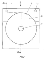
- 1 to 3 is a first embodiment a system for applying a flexible sheet of material 10.1 shown on a flat object 3. It consists of a composite 1, at least a carrier layer 10 and a wear layer 11 has, and a device 2 for applying the flexible material sheet 10.1 on the flat object 3.
- the flexible material sheet 10.1 is through formed a punched-out part of the wear layer 10, and in an edge area of the composite 1 are outside of the flexible material sheet 10.1 first means, in particular Punch holes 1.1, for aligning the flexible Sheet of material related to the flat object intended.
- the flexible material sheet serves as an embodiment 10.1 as a label for a CD.
- the flexible material sheet 10.1 is by punching lines 10.2 and 10.3 in the wear layer 10 is punched out.
- the flexible material sheet 10.1 and the remaining part of the wear layer 10 are held together by being on the support layer 11 stick.
- the wear layer 10 and thus also the flexible material sheet 10.1 self-adhesive.
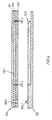
- the device 2 shown in FIGS. 2 and 3 to apply the flexible material sheet 10.1 the flat object 3 has a means 2.2 to fix the flat object 3 and second Means for aligning the flexible material sheet 10.1 with respect to the flat object 3.
- This second means are here through surveys, in particular Pins 2.1 formed, which are correspondingly complementary to the punched holes 1.1 of the composite 1 are.
- the distance between the two pins 2.1 corresponds the distance between the punched holes 1.1.
- the diameter the pin is slight, for example 1/10 mm, larger than the diameter of the register punchings.
- the composite 1 with its register punchings 1.1 hung in the pin 2.1 of the device 2 be so that between composite and device an immovable fit is created.
- the flat object 3 is formed by a CD, which in the middle is a usual circular recess has means 2.2 for fixing the CD for example formed by a centering ring, as he usually in the known CD cases is provided.
- the flat object 3 is within the scope of the invention by no means limited to a CD, but it rather, all objects are conceivable on the one flexible sheet of material could be applied. So the flat object could for example also formed by cards, printed sheets, etc. which are to be laminated with a transparent film.
- the means for fixing the flat object for example, through a corresponding recess are formed on the device 2 in the the flat object 3 is inserted.
- the device 2 has an exemplary embodiment also a recess 2.3 in which a part of the flat object 3 is added.
- the depth of the Recess 2.3 corresponds approximately to the thickness of the flat Item 3, so that the surface 2.4 of the Device 2 from which the pins 2.1 protrude upwards approximately flush with the surface of the device 2 fixed flat object 3 completes.
- Carrier layer 11 of the composite at least in two parts educated.
- the carrier layer 11 by a first part 11.1 and a second part 11.2 formed by a punch line 11.3 are separated from each other.
- the wear layer 10 is in the illustrated embodiment from the completely punched out flexible Material sheet 10.1, a first remaining part 10.4, a second remaining part 10.5 and one third remaining part 10.6, the third remaining Part 10.6 through the central circular Punching line 10.3 is formed and the first and second remaining part 10.4, 10.5 of the wear layer 10 through Punching lines 10.7 and 10.8 are separated from each other.
- both the backing layer and the remaining one Part of the wear layer is formed in two parts, can be used to apply the flexible material sheet 10.1 a partial area of the adhesive surface on the flat object 3 of the flexible material sheet 10.1 exposed be by the remaining part of the wear layer 10.5 together with the second part 11.2 of the carrier layer is separated from the rest of the network.
- the Cutting line 11.3 between the first and the second Part of the carrier layer runs such that a part of the second carrier element 11.2 also on the flexible Material sheet 10.1 is liable.
- the flat object should be labeled or printed.
- the network can do this for example using a conventional printer be printed before the flexible material sheet is applied becomes.
- this lettering or printing as possible little is rubbed off and a blurring of the Print image, for example by the action of Liquids to be avoided.
- the flexible material sheet could be used for such applications be formed by a transparent film, with which an already printed flat object is laminated can be.
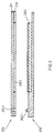
- 4 is a corresponding one Application shown.
- the device 102 for application corresponds in particular to the flexible material sheet 101 regarding the pins 102.1 of the device according to the first embodiment.
- the flat object 103 already printed and should have a transparent film 110 to be concealed.
- the flat object 103 can for example, it is a CD that already according to the first embodiment with a labeled Label has been provided. It can but can also be any printed card, which is to be protected with the transparent film.
- the composite 101 is constructed in three layers, in which case both the carrier layer 111 as well as the wear layer formed by the transparent film 110 is self-adhesive.
- the adhesive surface the wear layer 110 is then covered by a cover layer 120 covered.
- This cover layer can for example formed by a silicone masking paper become.
- the flexible material sheet 110.1 is again by a punched out along punching lines 110.2 Part of the wear layer 110 is formed. When punching out becomes the cover layer in addition to the wear layer 110 120 severed. The cohesion of the association will then ensured by the carrier layer 111.
- Punch holes 101.1 in turn work with pins 102.1 on the device 102 together, so that a precise fit Align the flexible sheet of material 110.1 with respect on the flat object 103 is guaranteed.
- the flat object 103 becomes the cover layer 120 removed at least in the area of the flexible material sheet, before the composite 101 is hooked into the pins 102.1 becomes.
- the covering layer 120 could do so are punched, as in the first embodiment along the punching line 11.3 in the carrier layer 11 has been shown. This could in turn initially only part of the cover paper from the flexible Material sheets 110.1 are removed, so that the Handling when hanging the composite in the device is facilitated. Once the flexible sheet of material 110.1 with the exposed adhesive surface on the flat Item 103 is liable, is a relative movement between both parts no longer possible, so that then easy way to remove the rest of the masking paper and the flexible material sheet completely the flat object 103 can be applied. Finally, the actual carrier layer 111 away.
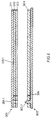
- the composite has 201 in turn a wear layer 210 and a carrier layer 211, wherein the wear layer 210 by a so-called backing film is formed, which in one commercially available printers first printed mirror-inverted becomes.
- the carrier layer 211 is self-adhesive formed, and the wear layer 210 with the punched out flexible material sheet 210.1 adheres to it Support layer.
- the flat object 203 has its to be provided with the flexible material sheet Already have an adhesive layer on the sides.
- the flat Item could be, for example, a blank card in the form of a credit card, one or both sides with an adhesive layer which is initially covered with masking paper. This blank card can then be removed by removing the cover paper for example with the printed backing film be provided.
- the special advantage of Using a backing film is that the printed part comes into contact with the adhesive surface and thus a high-gloss, protected surface arises.
- the flat object 203 only needs the compound 201 be hooked into the pin 202.1 in order to subsequently the punched out flexible material sheet 210.1 to press and close on the flat object fix.
- the embodiment of Figure 6 differs in particular by the means for fixing the flat Object. While in the previously described Embodiments of the flat object for example through a central centering ring and / or a correspondingly designed recess for Inserting the flat object has been formed is the flat object 303 in the embodiment 6 also by the pin 302.1 the device 302 fixed by the flat object in accordance with compound 301 as well Has register punchings with which the flat object 303 can be hooked into the device.
- the flat object 303 is, for example, by a conventional, printable sheet of paper or cardboard formed by a transparent film after printing should be protected.
- Compound 301 corresponds therefore from the structure of the composite 101 according to FIG. 4. Since usually the register punched on the laminated flat object 303 are perceived as disturbing, Appropriate measures can be taken to cover the area of the flat object 303, which the register punchings has to be removed after lamination. In the simplest case, this will be done by cutting off can reach this area. However, it is also conceivable, a perforation or, as shown, a narrow tape 304 to use after lamination the area with the register punchings to remove the flat object.
- the flat object is not provided with appropriate register punchings, but the flat object on a light adhesive Partial area of the device is placed, the orientation with the help of register marks on the device he follows.
- the device forms at least the device 2, 102, 202 at the same time part of a storage case for the flat Object.
- the device can be used as Insert tray designed for a conventional CD case his.
- the depth of the Recess for the CD to be inserted can be adjusted so that the top of the insert tray on which the tenon protrude flush with the surface of the CD Transition forms.
- the device for applying the flexible sheet of material can in particular also advantageously as a storage medium for the flat object (especially a CD) if the device as mentioned above, is provided with holes in which the Pin can be inserted to apply the flat sheet of material are.
- the cones can be removed again that the flat object together with the device can be stored in conventional ring folders.
- this presupposes that the distance between the holes the specified distance to the shelf in conventional Corresponds to ring folders.
Abstract
Description
Die Erfindung betrifft ein System zum Aufbringen eines flexiblen Materialbogens auf einen flächigen Gegenstand.The invention relates to a system for applying a flexible sheet of material on a flat object.
Zur Speicherung von Informationen aller Art, wie Musik und andere Daten, werden sogenannte CD's verwendet, die einmalig oder wiederholt beschreibbar sind. Zur Kennzeichnung dieser CD's werden beschriftbare Etiketten aufgeklebt.For storing information of all kinds, such as music and other data, so-called CD's are used can be written once or repeatedly. For identification these CDs become labels that can be written on glued.
Um nun diese Klebetiketten möglichst paßgenau auf die CD aufzubringen, sind die verschiedensten Systeme aus der Praxis bekannt.In order to fit these adhesive labels as precisely as possible on the The most diverse systems are used to apply CDs known in practice.
Bei einem bekannten System wird die bespielte CD in die CD-Hülle eingelegt, wobei die zu beklebende Seite nach oben zeigt. Anschließend wird eine Zentrierhilfe auf den mittigen Kranz aufgesetzt. Das Klebeetikett weist eine zentrale, kreisförmige Ausstanzung auf, die der Größe der Zentrierhilfe entspricht. Das Klebeetikett wird dann mit dieser mittigen Ausstanzung über die Zentrierhilfe geführt und angedrückt. Dieses System hat jedoch den Nachteil, daß es viel Übung und einer sehr ruhigen Hand bedarf, um das Klebeetikett möglichst exakt zentriert aufzubringen.In a known system, the recorded CD is in the CD case inserted, with the side to be glued facing shows above. Then a centering aid is opened put the central wreath on. The adhesive label shows a central, circular cut-out that the The size of the centering aid corresponds. The adhesive label is then with this central punch over the centering aid led and pressed. This system has however, the disadvantage that it is a lot of practice and a lot A steady hand is required to make the adhesive label as precise as possible centered.
In der DE 298 00 751 wird daher eine Anordnung zum Aufbringen eines Etiketts auf eine CD-ROM beschrieben, das aus einem Verbund besteht, der durch wenigstens eine Trägerschicht und eine Nutzschicht gebildet wird, wobei das Etikett durch einen ausgestanzten Teil der Nutzschicht gebildet wird und wobei ein Randbereich des Verbundes außerhalb des Etiketts eine Anlagehilfe bildet. Die Trägerschicht ist zweiteilig ausgebildet, so daß zum Aufbringen des Etiketts ein erster Teil des Trägermaterials vom Etikett abgezogen wird, so daß ein Teil der Klebefläche des Etiketts bereits freigegeben und der andere Teil der Klebefläche noch abgedeckt ist. Anschließend wird das Etikett mit der Anlagehilfe in die CD-Hülle eingelegt, wobei die Anlagehilfe an drei Seiten in Kontakt mit der CD-Hülle kommt und dadurch den Verbund ausrichtet. Das Etikett wird dann mit der bereits freigelegten Klebefläche auf der CD festgedrückt, anschließend wird der abgedeckte Teil des Etiketts umgeklappt und das restliche Trägermaterial zusammen mit der Anlagehilfe entfernt. Das Etikett kann dann vollständig auf die CD aufgeklebt werden.DE 298 00 751 therefore describes an arrangement for application described a label on a CD-ROM, the consists of a composite consisting of at least one Carrier layer and a wear layer is formed, wherein the label through a punched-out part of the wear layer is formed and wherein an edge region of the Compound forms an investment aid outside of the label. The carrier layer is formed in two parts, so that to apply the label a first part of the Carrier material is pulled off the label, so that a Part of the adhesive surface of the label has already been released and the other part of the adhesive surface is still covered. Then the label with the investment aid in inserted the CD case, the investment aid on three Sides comes into contact with the CD case and thereby aligns the network. The label is then with the the previously exposed adhesive surface is pressed onto the CD, then the covered part of the label folded and the rest of the backing material together removed with the investment aid. The label can then be completely glued to the CD.
Dieses bekannte System ist zwar etwas leichter zu handhaben, hat jedoch den Nachteil, daß ein exaktes Ausrichten kaum möglich ist, da die CD-Hüllen im Anlagebereich eine Entformungsschräge aufweisen, die sehr leicht zu fehlerhaften Ausrichtungen führen kann. Nachdem eine Teilfläche des Etiketts bereits vor dem Anlegen freigelegt ist, kann es außerdem bereits während des Einlegens zu einem ungewollten Festkleben des Etiketts an der CD kommen.This known system is a little easier to use, has the disadvantage, however, that exact alignment is hardly possible because the CD covers in the investment area have a draft angle that is very can easily lead to incorrect alignments. After this a partial area of the label before the application is also exposed during of inserting the label inadvertently come on the CD.
Der Erfindung liegt daher die Aufgabe zugrunde, ein System zum Aufbringen eines flexiblen Materialbogens auf einen flächigen Gegenstand anzugeben, welches einfach zu handhaben und ein paßgenaues Aufbringen ermöglicht.The invention is therefore based on the object of a system to apply a flexible sheet of material specify a flat object that is simple to handle and a precisely fitting application enables.
Erfindungsgemäß wird diese Aufgabe durch die Merkmale des Anspruches 1 gelöst. According to the invention, this object is achieved by the features of claim 1 solved.
Erfindungsgemäß besteht das System zum Aufbringen eines flexiblen Materialbogens auf einen flächigen Gegenstand aus
- einem Verbund, der wenigstens eine Trägerschicht und eine Nutzschicht aufweist, wobei ein ausgestanzter Teil der Nutzschicht den flexiblen Materialbogen bildet und wobei in einem Randbereich des Verbundes außerhalb des flexiblen Materialbogens erste Mittel zum Ausrichten des flexiblen Materialbogens in bezug auf den flächigen Gegenstand vorgesehen sind,
- sowie einer Vorrichtung zum Aufbringen des flexiblen Materialbogens auf den flächigen Gegenstand, enthaltend Mittel zum Fixieren des flächigen Gegenstand sowie zweite Mittel zum Ausrichten des flexiblen Materialbogens in bezug auf den flächigen Gegenstand.
- a composite which has at least one carrier layer and a wear layer, a punched-out part of the wear layer forming the flexible material sheet and wherein in an edge region of the composite outside the flexible material sheet first means for aligning the flexible material sheet with respect to the flat object are provided,
- and a device for applying the flexible material sheet to the flat object, containing means for fixing the flat object and second means for aligning the flexible material sheet with respect to the flat object.
Die ersten Mittel zum Ausrichten werden durch wenigstens eine Ausstanzung und die zweiten Mittel zum Ausrichten durch wenigstens eine komplementär ausgebildete Erhebung gebildet, wobei der Verbund mit der Ausstanzung derart in die Erhebung der Vorrichtung einhängbar ist, daß zwischen Verbund und Vorrichtung eine unverrückbare Passung entsteht.The first means of alignment are by at least a die cut and the second means for alignment by at least one complementary Elevation formed, the association with the punching can be suspended in the elevation of the device in this way is that between assembly and device an immovable Fit is created.
Weitere Ausgestaltungen der Erfindung sind Gegenstand der Unteransprüche.Further refinements of the invention are the subject of subclaims.
In einem bevorzugten Ausführungsbeispiel werden die ersten Mittel zum Ausrichten durch zwei beabstandete, vorzugsweise kreisrunde Passerstanzungen und die zweiten Mittel durch zwei Erhebungen, insbesondere zwei entsprechend komplementär ausgestaltete Zapfen gebildet.In a preferred embodiment, the first Alignment means by two spaced preferably circular register punchings and the second Funded by two surveys, particularly two appropriately complementary cones formed.
Weitere Ausgestaltungen und Vorteile der Erfindung werden anhand einiger Ausführungsbeispiele und der Zeichnung näher erläutert. In der Zeichnung zeigen
- Fig.1
- eine Aufsicht des Verbundes gemäß einem ersten Ausführungsbeispiel,
- Fig.2
- eine Aufsicht der Vorrichtung zum Aufbringen des flexiblen Materialbogens,
- Fig.3
- eine Schnittdarstellung des Systems zum Aufbringen eines flexiblen Materialbogens gemäß der Schnittlinie III-III der Figuren 1 und 2,
- Fig.4
- eine Schnittdarstellung des Systems gemäß einem zweiten Ausführungsbeispiel,
- Fig.5
- eine Schnittdarstellung des Systems gemäß einem dritten Ausführungsbeispiel und
- Fig.6
- eine Schnittdarstellung des Systems gemäß einem vierten Ausführungsbeispiel.
- Fig.1
- a top view of the composite according to a first embodiment,
- Fig.2
- a top view of the device for applying the flexible material sheet,
- Figure 3
- 2 shows a sectional view of the system for applying a flexible material sheet according to the section line III-III of FIGS. 1 and 2,
- Figure 4
- 3 shows a sectional illustration of the system according to a second exemplary embodiment,
- Figure 5
- a sectional view of the system according to a third embodiment and
- Figure 6
- a sectional view of the system according to a fourth embodiment.
In den Figuren 1 bis 3 ist ein erstes Ausführungsbeispiel
eines Systems zum Aufbringen eines flexiblen Materialbogens
10.1 auf einen flächigen Gegenstand 3 dargestellt.
Er besteht aus einem Verbund 1, der wenigstens
eine Trägerschicht 10 und eine Nutzschicht 11
aufweist, sowie einer Vorrichtung 2 zum Aufbringen des
flexiblen Materialbogens 10.1 auf den flächigen Gegenstand
3. Der flexible Materialbogen 10.1 wird durch
einen ausgestanzten Teil der Nutzschicht 10 gebildet,
und in einem Randbereich des Verbundes 1 sind außerhalb
des flexiblen Materialbogens 10.1 erste Mittel, insbesondere
Passerstanzungen 1.1, zum Ausrichten des flexiblen
Materialbogens in bezug auf den flächigen Gegenstand
vorgesehen.1 to 3 is a first embodiment
a system for applying a flexible sheet of material
10.1 shown on a
Wie insbesondere aus Fig.1 zu ersehen ist, sind bei
diesem Ausführungsbeispiel zwei beabstandete, kreisrunde
Passerstanzungen 1.1 vorgesehen. Im dargestellten
Ausführungsbeispiel dient der flexible Materialbogen
10.1 als Etikett für eine CD. Der flexible Materialbogen
10.1 ist dabei durch Stanzlinien 10.2 und 10.3 in
der Nutzschicht 10 ausgestanzt. Der flexible Materialbogen
10.1 und der verbleibende Teil der Nutzschicht 10
werden dadurch zusammengehalten, daß sie an der Trägerschicht
11 haften. Im vorliegenden Fall ist die Nutzschicht
10 und damit auch der flexible Materialbogen
10.1 selbstklebend ausgebildet.As can be seen in particular from FIG. 1, at
this embodiment two spaced, circular
Punching holes 1.1 provided. In the illustrated
The flexible material sheet serves as an embodiment
10.1 as a label for a CD. The flexible material sheet
10.1 is by punching lines 10.2 and 10.3 in
the
Die in den Figuren 2 und 3 dargestellte Vorrichtung 2
zum Aufbringen des flexiblen Materialbogens 10.1 auf
den flächigen Gegenstand 3 weist zum einen Mittel 2.2
zum Fixieren des flächigen Gegenstandes 3 sowie zweite
Mittel zum Ausrichten des flexiblen Materialbogens 10.1
in bezug auf den flächigen Gegenstand 3 auf. Diese
zweiten Mittel werden hier durch Erhebungen, insbesondere
Zapfen 2.1 gebildet, die entsprechend komplementär
zu den Passerstanzungen 1.1 des Verbundes 1 ausgebildet
sind. Der Abstand der beiden Zapfen 2.1 entspricht dabei
dem Abstand der Passerstanzungen 1.1. Der Durchmesser
der Zapfen ist geringfügig, beispielsweise 1/10 mm,
größer als der Durchmesser der Passerstanzungen. Auf
diese Weise kann der Verbund 1 mit seinen Passerstanzungen
1.1 in den Zapfen 2.1 der Vorrichtung 2 eingehängt
werden, so daß zwischen Verbund und Vorrichtung
eine unverrückbare Passung entsteht.The
Wird der flächige Gegenstand 3 durch eine CD gebildet,
welche in der Mitte eine übliche kreisrunde Aussparung
aufweist, können die Mittel 2.2 zum Fixieren der CD
beispielsweise durch einen Zentrierkranz gebildet werden,
wie er üblicherweise in den bekannten CD-Hüllen
vorgesehen ist.If the
Der flächige Gegenstand 3 ist jedoch im Rahmen der Erfindung
keineswegs auf eine CD beschränkt, sondern es
sind vielmehr alle Gegenstände denkbar, auf die ein
flexibler Materialbogen aufgebracht werden könnte. So
könnte der flächige Gegenstand beispielsweise auch
durch Karten, bedruckte Bögen, etc. gebildet werden,
die mit einer Klarsichtfolie kaschiert werden sollen.However, the
Insbesondere bei flächigen Gegenständen, die keine Fixierung
mittels eines Zentrierkranzes 2.2 erlauben,
können die Mittel zum Fixieren des flächigen Gegenstandes
beispielsweise auch durch eine entsprechende Ausnehmung
an der Vorrichtung 2 gebildet werden, in die
der flächige Gegenstand 3 eingelegt wird. Im dargestellten
Ausführungsbeispiel weist die Vorrichtung 2
ebenfalls eine Ausnehmung 2.3 auf, in der ein Teil des
flächigen Gegenstands 3 aufgenommen wird. Die Tiefe der
Ausnehmung 2.3 entspricht in etwa der Stärke des flächigen
Gegenstands 3, so daß die Oberfläche 2.4 der
Vorrichtung 2, aus der die Zapfen 2.1 nach oben ragen,
etwa bündig mit der Oberfläche des in der Vorrichtung 2
fixierten flächigen Gegenstands 3 abschließt. Especially for flat objects that have no fixation
allow by means of a centering ring 2.2,
can the means for fixing the flat object
for example, through a corresponding recess
are formed on the
Um die Handhabung des Systems zum Aufbringen des flexiblen
Materialbogens weiter zu vereinfachen, ist die
Trägerschicht 11 des Verbundes wenigstens zweiteilig
ausgebildet. Im dargestellten Ausführungsbeispiel wird
die Trägerschicht 11 durch einen ersten Teil 11.1 und
einen zweiten Teil 11.2 gebildet, die durch eine Stanzlinie
11.3 voneinander getrennt sind.To handle the system to apply the flexible
To further simplify the material sheet is
Die Nutzschicht 10 besteht im dargestellten Ausführungsbeispiel
aus dem völlig ausgestanzten flexiblen
Materialbogen 10.1, einem ersten verbleibenden Teil
10.4, einem zweiten verbleibenden Teil 10.5 und einem
dritten verbleibenden Teil 10.6, wobei der dritte verbleibende
Teil 10.6 durch die zentrale kreisrunde
Stanzlinie 10.3 gebildet wird und der erste und zweite
verbleibende Teil 10.4, 10.5 der Nutzschicht 10 durch
Stanzlinien 10.7 und 10.8 voneinander getrennt sind.The
Indem sowohl die Trägerschicht als auch der verbleibende
Teil der Nutzschicht zweiteilig ausgebildet ist,
kann zum Aufbringen des flexiblen Materialbogens 10.1
auf den flächigen Gegenstand 3 ein Teilbereich der Klebefläche
des flexiblen Materialbogens 10.1 freigelegt
werden, indem der verbleibende Teil der Nutzschicht
10.5 zusammen mit dem zweiten Teil 11.2 der Trägerschicht
vom restlichen Verbund getrennt wird. Die
Stanzlinie 11.3 zwischen dem ersten und dem zweiten
Teil der Trägerschicht verläuft derart, daß ein Teil
des zweiten Trägerelements 11.2 auch am flexiblen
Materialbogen 10.1 haftet. Durch Entfernen dieses zweiten
Teils 11.2 der Trägerschicht wird somit der durch
diesen Teil abgedeckte Bereich der Klebeschicht des
flexiblen Materialbogens freigelegt. By both the backing layer and the remaining one
Part of the wear layer is formed in two parts,
can be used to apply the flexible material sheet 10.1
a partial area of the adhesive surface on the
Im Anschluß hieran wird der verbleibende Verbund mit
seinen Passerstanzungen 1.1 in den Zapfen 2.1 der Vorrichtung
eingehängt. Anschließend wird der Verbund,
insbesondere der Materialbogen 10.1 im Bereich der
freigelegten Klebefläche auf dem flächigen Gegenstand 3
festgedrückt. Indem diese freigelegte Fläche genügend
groß gewählt wird, ist dann ein unbeabsichtigtes Verschieben
des flexiblen Materialbogens gegenüber dem
flächigen Gegenstand nicht mehr möglich. Im Anschluß
hieran wird der noch am flexiblen Materialbogen haftende
erste Teil der Trägerschicht abgezogen, so daß
der flexible Materialbogen vollständig auf dem flächigen
Gegenstand mittels seiner Selbstklebeschicht aufgebracht
werden kann. Zum Ablösen des verbleibenden ersten
Teils der Trägerschicht wird der Verbund 1 alleine
oder zusammen mit dem flächigen Gegenstand von den Zapfen
2.1 abgenommen.Following this, the remaining association with
its register punch 1.1 in the pin 2.1 of the device
hooked. Then the composite,
in particular the material sheet 10.1 in the area of
exposed adhesive surface on the
In vielen Anwendungen soll der flächige Gegenstand beschriftet bzw. bedruckt werden. Der Verbund kann hierfür beispielsweise mittels eines herkömmlichen Druckers bedruckt werden, bevor der flexible Materialbogen aufgebracht wird. Für manchen Anwendungen ist es nun erforderlich, daß diese Beschriftung bzw. Bedruckung möglichst wenig abgerieben wird und ein Verwischen des Druckbildes, beispielsweise durch Einwirkungen von Flüssigkeiten, vermieden werden soll.In many applications, the flat object should be labeled or printed. The network can do this for example using a conventional printer be printed before the flexible material sheet is applied becomes. For some applications it is now necessary that this lettering or printing as possible little is rubbed off and a blurring of the Print image, for example by the action of Liquids to be avoided.
Für derartige Anwendungsfälle könnte der flexible Materialbogen
durch eine Klarsichtfolie gebildet werden,
mit der ein bereits bedruckter flächiger Gegenstand kaschiert
werden kann. In Fig.4 ist eine entsprechende
Anwendung dargestellt. Die Vorrichtung 102 zum Aufbringen
des flexiblen Materialbogens 101 entspricht insbesondere
hinsichtlich der Zapfen 102.1 der Vorrichtung
gemäß dem ersten Ausführungsbeispiel. Im Ausführungsbeispiel
gemäß Fig.4 ist der flächige Gegenstand 103
bereits bedruckt und soll mit einer Klarsichtfolie 110
kaschiert werden. Bei dem flächigen Gegenstand 103 kann
es sich beispielsweise um eine CD handeln, die bereits
gemäß dem ersten Ausführungsbeispiel mit einem beschrifteten
Etikett versehen worden ist. Es kann sich
jedoch auch um eine beliebige, bedruckte Karte handeln,
die mit der Klarsichtfolie geschützt werden soll.The flexible material sheet could be used for such applications
be formed by a transparent film,
with which an already printed flat object is laminated
can be. 4 is a corresponding one
Application shown. The
Der Verbund 101 ist in diesem Fall dreischichtig aufgebaut,
wobei in diesem Fall sowohl die Trägerschicht 111
als auch die durch die Klarsichtfolie gebildete Nutzschicht
110 selbstklebend ausgebildet ist. Die Klebefläche
der Nutzschicht 110 ist dann noch durch eine Abdeckschicht
120 abgedeckt. Diese Abdeckschicht kann
beispielsweise durch ein Silikon-Abdeckpapier gebildet
werden. Der flexible Materialbogen 110.1 wird wiederum
durch einen entlang von Stanzlinien 110.2 ausgestanzten
Teil der Nutzschicht 110 gebildet. Bei der Ausstanzung
wird neben der Nutzschicht 110 auch die Abdeckschicht
120 durchtrennt. Der Zusammenhalt des Verbundes wird
dann durch die Trägerschicht 111 gewährleistet.
Passerstanzungen 101.1 wirken wiederum mit Zapfen 102.1
an der Vorrichtung 102 zusammen, so daß ein paßgenaues
Ausrichten des flexiblen Materialbogens 110.1 in bezug
auf den flächigen Gegenstand 103 gewährleistet ist.
Beim Aufbringen des flexiblen Materialbogens 110.1 auf
den flächigen Gegenstand 103 wird die Abdeckschicht 120
zumindest im Bereich des flexiblen Materialbogens entfernt,
bevor der Verbund 101 in die Zapfen 102.1 eingehängt
wird. In this case, the composite 101 is constructed in three layers,
in which case both the
Im Rahmen der Erfindung könnte die Abdeckschicht 120 so
gestanzt werden, wie dies beim ersten Ausführungsbeispiel
entlang der Stanzlinie 11.3 in der Trägerschicht
11 dargestellt worden ist. Dadurch könnte wiederum
zunächst nur ein Teil des Abdeckpapiers vom flexiblen
Materialbogen 110.1 entfernt werden, so daß dadurch die
Handhabung beim Einhängen des Verbundes in die Vorrichtung
erleichtert wird. Sobald der flexible Materialbogen
110.1 mit der freigelegten Klebefläche am flächigen
Gegenstand 103 haftet, ist eine Relativbewegung zwischen
beiden Teilen nicht mehr möglich, so daß dann auf
einfache Art und Weise das restliche Abdeckpapier entfernt
und der flexible Materialbogen vollständig auf
den flächigen Gegenstand 103 aufgebracht werden kann.
Zum Schluß wird dann die eigentliche Trägerschicht 111
entfernt.In the context of the invention, the
Im Ausführungsbeispiel gemäß Fig.5 weist der Verbund
201 wiederum eine Nutzschicht 210 und eine Trägerschicht
211 auf, wobei die Nutzschicht 210 durch eine
sogenannte Hinterdruckfolie gebildet wird, die in einem
handelsüblichen Drucker zunächst spiegelverkehrt bedruckt
wird. Die Trägerschicht 211 ist selbstklebend
ausgebildet, und die Nutzschicht 210 mit dem ausgestanzten
flexiblen Materialbogen 210.1 haftet an dieser
Trägerschicht. Der flächige Gegenstand 203 weist auf
seiner mit dem flexiblen Materialbogen zu versehenden
Seiten bereits eine Klebeschicht auf. Der flächige
Gegenstand könnte beispielsweise durch einen Karten-Rohling
im Format einer Kreditkarte gebildet werden,
der ein oder beidseitig mit einer Klebeschicht versehen
ist, die zunächst mit einem Abdeckpapier abgedeckt ist.
Durch Entfernen des Abdeckpapiers kann dann dieser Karten-Rohling
beispielsweise mit der bedruckten Hinterdruckfolie
versehen werden. Der besondere Vorteil der
Verwendung einer Hinterdruckfolie besteht darin, daß
der bedruckte Teil mit der Klebefläche in Kontakt kommt
und somit eine hochglänzende, geschützte Oberfläche
entsteht.In the exemplary embodiment according to FIG. 5, the composite has
201 in turn a
Zum Aufbringen des flexiblen Materialbogens 210.1 auf
den flächigen Gegenstand 203 muß der Verbund 201 lediglich
in die Zapfen 202.1 eingehängt werden, um anschließend
den ausgestanzten flexiblen Materialbogen
210.1 auf den flächigen Gegenstand zu drücken und zu
fixieren.To apply the flexible material sheet 210.1
the
Im Rahmen der Erfindung wäre es auch denkbar, daß man die auf dem flächigen Gegenstand vorhandene Klebeschicht selbst mit Hilfe des erfindungsgemäßen Systems aufbringt, indem die Nutzschicht des Verbundes durch einen doppelseitig klebenden Zwischenträger gebildet wird, der auf einen flächigen Gegenstand aufgebracht wird. Im Rahmen der Erfindung ist es somit auch möglich, mehrere, gegebenenfalls aus unterschiedlichem Material bestehende flexible Materialbögen auf einen flächigen Gegenstand aufzubringen. Bei dem Ausführungsbeispiel gemäß Fig.5 könnte in einem ersten Verfahrensschritt zunächst der doppelseitig klebende Zwischenträger und im Anschluß hieran die Hinterdruckfolie aufgebracht werden.Within the scope of the invention it would also be conceivable that one the adhesive layer present on the flat object even with the help of the system according to the invention by applying the wear layer of the composite formed a double-sided adhesive intermediate carrier is applied to a flat object becomes. In the context of the invention it is therefore also possible several, possibly made of different materials existing flexible material sheets on a flat Apply object. In the embodiment 5 could in a first process step first the double-sided adhesive intermediate carrier and then applied the backing film become.
Das Ausführungsbeispiel gemäß Fig.6 unterscheidet sich
insbesondere durch die Mittel zum Fixieren des flächigen
Gegenstands. Während in den zuvor beschriebenen
Ausführungsbeispielen der flächige Gegenstand beispielsweise
durch einen zentralen Zentrierkranz
und/oder eine entsprechend ausgebildete Ausnehmung zum
Einlegen des flächigen Gegenstandes gebildet worden
ist, wird der flächige Gegenstand 303 beim Ausführungsbeispiel
gemäß Fig.6 ebenfalls durch die Zapfen 302.1
der Vorrichtung 302 fixiert, indem der flächige Gegenstand
in Übereinstimmung mit dem Verbund 301 ebenfalls
Passerstanzungen aufweist, mit denen der flächige Gegenstand
303 in die Vorrichtung einhängbar ist.The embodiment of Figure 6 differs
in particular by the means for fixing the flat
Object. While in the previously described
Embodiments of the flat object for example
through a central centering ring
and / or a correspondingly designed recess for
Inserting the flat object has been formed
is the
Der flächige Gegenstand 303 wird beispielsweise durch
einen herkömmlichen, bedruckbaren Papier- oder Kartonbogen
gebildet, der nach dem Bedrucken durch eine Klarsichtfolie
geschützt werden soll. Der Verbund 301 entspricht
daher vom Aufbau dem Verbund 101 gemäß Fig.4.
Da üblicherweise die Passerstanzungen am kaschierten
flächigen Gegenstand 303 als störend empfunden werden,
können geeignete Maßnahmen ergriffen werden, um den Bereich
des flächigen Gegenstands 303, der die Passerstanzungen
aufweist, nach dem Kaschieren zu entfernen.
Im einfachsten Fall wird man dies durch Abschneiden
dieses Bereichs erreichen können. Es ist jedoch auch
denkbar, eine Perforation oder, wie dargestellt, ein
schmales Klebeband 304 zu verwenden, um nach dem Kaschieren
den mit den Passerstanzungen versehenen Bereich
des flächigen Gegenstands zu entfernen.The
Es ist ferner auch denkbar, daß der flächige Gegenstand nicht mit entsprechenden Passerstanzungen versehen ist, sondern der flächige Gegenstand auf eine leichtklebende Teilfläche der Vorrichtung gelegt wird, wobei die Ausrichtung mit Hilfe von Passer-Markierungen auf der Vorrichtung erfolgt. It is also conceivable that the flat object is not provided with appropriate register punchings, but the flat object on a light adhesive Partial area of the device is placed, the orientation with the help of register marks on the device he follows.
Im Rahmen der Erfindung ist es ferner denkbar, daß im Bereich der Erhebungen der Vorrichtung Aussparungen, insbesondere Löcher vorgesehen sind, in die die Zapfen 2.1, 102.1, 202.1 einsteckbar sind.In the context of the invention it is also conceivable that in Area of the elevations of the device recesses, in particular holes are provided in which the pins 2.1, 102.1, 202.1 can be inserted.
In einer weiteren vorteilhaften Ausgestaltung bildet
die Vorrichtung 2, 102, 202 gleichzeitig wenigstens
einen Teil einer Aufbewahrungshülle für den flächigen
Gegenstand. So kann die Vorrichtung beispielsweise als
Einlage-Tray für eine herkömmliche CD-Hülle ausgebildet
sein. In diesem Fall müßte ein herkömmliches Einlage-Tray
für eine CD-Hülle lediglich mit entsprechenden
Zapfen (bzw. Löchern für einsteckbare Zapfen) versehen
werden. Vorteilhafterweise müßte ferner die Tiefe der
Aussparung für die einzulegende CD so angepaßt werden,
daß die Oberseite des Einlage-Trays, auf der die Zapfen
hervorragen, mit der Oberfläche der CD einen bündigen
Übergang bildet.In a further advantageous embodiment forms
at least the
Die Vorrichtung zum Aufbringen des flexiblen Materialbogens kann insbesondere auch dann vorteilhafterweise als Aufbewahrungsmittel des flächigen Gegenstands (insbesondere einer CD) dienen wenn die Vorrichtung, wie oben erwähnt, mit Löchern versehen ist, in die die Zapfen zum Aufbringen des flächigen Materialbogens einsteckbar sind. Nach dem Aufbringen des flächigen Materialbogens können die Zapfen wieder entfernt werden, so daß der flächige Gegenstand zusammen mit der Vorrichtung in herkömmlichen Ringordnern abgelegt werden kann. Dies setzt natürlich voraus, daß der Abstand der Löcher dem vorgegebenen Abstand zur Ablage in herkömmlichen Ringordnern entspricht. The device for applying the flexible sheet of material can in particular also advantageously as a storage medium for the flat object (especially a CD) if the device as mentioned above, is provided with holes in which the Pin can be inserted to apply the flat sheet of material are. After applying the flat sheet of material the cones can be removed again that the flat object together with the device can be stored in conventional ring folders. Of course, this presupposes that the distance between the holes the specified distance to the shelf in conventional Corresponds to ring folders.
Die oben beschriebenen verschiedenen Varianten des erfindungsgemäßen Systems ermöglichen ein paßgenaues Bekleben von flächigen Gegenständen, wobei das System für die verschiedensten Anwendungen ausgelegt werden kann.The various variants of the invention described above Systems make it possible to glue them precisely of flat objects, the system for the most diverse applications can be designed.
Claims (10)
Applications Claiming Priority (2)
| Application Number | Priority Date | Filing Date | Title |
|---|---|---|---|
| DE2001127256 DE10127256C2 (en) | 2001-06-05 | 2001-06-05 | System for applying a flexible sheet of material |
| DE10127256 | 2001-06-05 |
Publications (3)
| Publication Number | Publication Date |
|---|---|
| EP1264772A2 true EP1264772A2 (en) | 2002-12-11 |
| EP1264772A3 EP1264772A3 (en) | 2003-01-02 |
| EP1264772B1 EP1264772B1 (en) | 2004-07-07 |
Family
ID=7687249
Family Applications (1)
| Application Number | Title | Priority Date | Filing Date |
|---|---|---|---|
| EP20020001695 Expired - Lifetime EP1264772B1 (en) | 2001-06-05 | 2002-01-24 | Labelling device for CDs |
Country Status (3)
| Country | Link |
|---|---|
| EP (1) | EP1264772B1 (en) |
| DE (1) | DE10127256C2 (en) |
| ES (1) | ES2223971T3 (en) |
Cited By (5)
| Publication number | Priority date | Publication date | Assignee | Title |
|---|---|---|---|---|
| WO2004064013A2 (en) * | 2003-01-10 | 2004-07-29 | Flynn Timothy J | Label assembly and apparatus for applying a label |
| US6799621B2 (en) * | 2003-01-10 | 2004-10-05 | Timothy J. Flynn | Label assembly and apparatus |
| US6881461B2 (en) | 2003-01-10 | 2005-04-19 | Timothy J. Flynn | Indexable label assembly |
| US6932133B1 (en) | 2004-02-03 | 2005-08-23 | Timothy J. Flynn | Apparatus and method for transferring a label portion from a label assembly onto an object |
| US7001476B2 (en) | 2004-02-03 | 2006-02-21 | Flynn Timothy J | Apparatus and method for transferring a label portion from a label assembly onto an object |
Citations (1)
| Publication number | Priority date | Publication date | Assignee | Title |
|---|---|---|---|---|
| DE29800751U1 (en) | 1997-01-23 | 1998-06-18 | Hermann Gmbh Co Heinrich | Arrangement with a flexible labelable label material |
Family Cites Families (6)
| Publication number | Priority date | Publication date | Assignee | Title |
|---|---|---|---|---|
| DE8306207U1 (en) * | 1983-11-03 | Georg Kohl GmbH + Co, 7129 Brackenheim | Receipt card with marking label, especially for examination results in hospitals, clinics, etc. | |
| DE2701911A1 (en) * | 1977-01-19 | 1978-07-20 | Eppendorf Geraetebau Netheler | Test tube with machine readable label - with spaced bosses for locating cut=outs on partly adhesive label |
| DE29617424U1 (en) * | 1996-06-05 | 1996-12-05 | Clausnitzer Werner | Device for applying a label to a compact disc or the like. |
| JP2001521469A (en) * | 1996-12-31 | 2001-11-06 | ダイノシス アクチェンゲェゼルシャフト | Method and apparatus for applying a self-adhesive label to a disk-shaped object |
| DE20012331U1 (en) * | 1999-07-30 | 2001-02-22 | Clausnitzer Sen | Adapter device for a CD labeling device |
| SE9903758L (en) * | 1999-10-18 | 2001-04-19 | Thord Roenngard | Ways to affix a label to a CD and label and device for carrying out the method |
-
2001
- 2001-06-05 DE DE2001127256 patent/DE10127256C2/en not_active Expired - Fee Related
-
2002
- 2002-01-24 ES ES02001695T patent/ES2223971T3/en not_active Expired - Lifetime
- 2002-01-24 EP EP20020001695 patent/EP1264772B1/en not_active Expired - Lifetime
Patent Citations (1)
| Publication number | Priority date | Publication date | Assignee | Title |
|---|---|---|---|---|
| DE29800751U1 (en) | 1997-01-23 | 1998-06-18 | Hermann Gmbh Co Heinrich | Arrangement with a flexible labelable label material |
Cited By (7)
| Publication number | Priority date | Publication date | Assignee | Title |
|---|---|---|---|---|
| WO2004064013A2 (en) * | 2003-01-10 | 2004-07-29 | Flynn Timothy J | Label assembly and apparatus for applying a label |
| US6799621B2 (en) * | 2003-01-10 | 2004-10-05 | Timothy J. Flynn | Label assembly and apparatus |
| US6881461B2 (en) | 2003-01-10 | 2005-04-19 | Timothy J. Flynn | Indexable label assembly |
| WO2004064013A3 (en) * | 2003-01-10 | 2005-09-22 | Timothy J Flynn | Label assembly and apparatus for applying a label |
| US6955843B2 (en) | 2003-01-10 | 2005-10-18 | Flynn Timothy J | Label assembly |
| US6932133B1 (en) | 2004-02-03 | 2005-08-23 | Timothy J. Flynn | Apparatus and method for transferring a label portion from a label assembly onto an object |
| US7001476B2 (en) | 2004-02-03 | 2006-02-21 | Flynn Timothy J | Apparatus and method for transferring a label portion from a label assembly onto an object |
Also Published As
| Publication number | Publication date |
|---|---|
| EP1264772B1 (en) | 2004-07-07 |
| ES2223971T3 (en) | 2005-03-01 |
| DE10127256A1 (en) | 2002-12-12 |
| EP1264772A3 (en) | 2003-01-02 |
| DE10127256C2 (en) | 2003-04-24 |
Similar Documents
| Publication | Publication Date | Title |
|---|---|---|
| EP0946936B1 (en) | Label for labelling preferably cylindrical containers and a container with a label of this type | |
| EP1581395B1 (en) | Individualised security document | |
| DE60128221T2 (en) | LABEL STRUCTURE FOR COMPACT DISCS | |
| EP1264772B1 (en) | Labelling device for CDs | |
| EP1319601A2 (en) | Method and device for labelling a CD | |
| DE19929679C1 (en) | Material web with cover label and method and device for processing such a material web | |
| EP1295733B1 (en) | Form, and method for the fabrication of a form with an integrated RFID transponder | |
| DE60201715T2 (en) | Spacer with peelable films of identifiable thickness | |
| EP0849093A1 (en) | Form with integrated card | |
| DE10017141A1 (en) | Labeling media, method for its production and method for labeling an object | |
| DE10227230A9 (en) | Arrangement and method for centering a label on a data carrier | |
| EP0917123A2 (en) | Laminatable label and method for its production | |
| DE102016110380B4 (en) | Adhesive sticker with a labeling field | |
| EP3156252B1 (en) | System zum aufbringen eines sicherheitsaufklebers auf ein objekt und entsprechendes verfahren | |
| EP0989085B1 (en) | Label strip | |
| EP1024468B1 (en) | Label sheet | |
| DE2802122A1 (en) | Written or printed tickets protected by cover film - are punched out of adhesive tape, turned over and stuck back on adhesive substrate | |
| DE10161430C1 (en) | Labeling of CDs or DVDs using sticky labels mounted on support backing paper with stamped lines in the label layer, support layer and both layers that facilitate accurate removal and centering of the labels on the disks | |
| DE4429198C1 (en) | Document holder with backing esp. for identity cards | |
| DE4017635C2 (en) | ||
| AT395696B (en) | Template for writing cheques | |
| EP1481385A1 (en) | Object with folded card glued thereto, method and multi-layered material for production thereof | |
| DE102010054962A1 (en) | Self-adhesive type carrier e.g. adhesive label for identity card, has linear perforation that is provided in front face of carrier film and is provided between optical visible region and rear contact surface of touching tab | |
| DE202005019573U1 (en) | Booklet strip for holding documents, has self-adhesive layer and removable strip section for covering self-adhesive layer, in which bonding area is formed for attachment to edge of document | |
| EP1336568A1 (en) | Manual labelling device |
Legal Events
| Date | Code | Title | Description |
|---|---|---|---|
| PUAI | Public reference made under article 153(3) epc to a published international application that has entered the european phase |
Free format text: ORIGINAL CODE: 0009012 |
|
| PUAL | Search report despatched |
Free format text: ORIGINAL CODE: 0009013 |
|
| AK | Designated contracting states |
Kind code of ref document: A2 Designated state(s): AT BE CH CY DE DK ES FI FR GB GR IE IT LI LU MC NL PT SE TR |
|
| AX | Request for extension of the european patent |
Free format text: AL;LT;LV;MK;RO;SI |
|
| AK | Designated contracting states |
Kind code of ref document: A3 Designated state(s): AT BE CH CY DE DK ES FI FR GB GR IE IT LI LU MC NL PT SE TR |
|
| AX | Request for extension of the european patent |
Free format text: AL;LT;LV;MK;RO;SI |
|
| 17P | Request for examination filed |
Effective date: 20030115 |
|
| GRAP | Despatch of communication of intention to grant a patent |
Free format text: ORIGINAL CODE: EPIDOSNIGR1 |
|
| AKX | Designation fees paid |
Designated state(s): CH ES FR GB IT LI PT |
|
| GRAS | Grant fee paid |
Free format text: ORIGINAL CODE: EPIDOSNIGR3 |
|
| REG | Reference to a national code |
Ref country code: DE Ref legal event code: 8566 |
|
| GRAA | (expected) grant |
Free format text: ORIGINAL CODE: 0009210 |
|
| AK | Designated contracting states |
Kind code of ref document: B1 Designated state(s): CH ES FR GB IT LI PT |
|
| PG25 | Lapsed in a contracting state [announced via postgrant information from national office to epo] |
Ref country code: IT Free format text: LAPSE BECAUSE OF FAILURE TO SUBMIT A TRANSLATION OF THE DESCRIPTION OR TO PAY THE FEE WITHIN THE PRESCRIBED TIME-LIMIT;WARNING: LAPSES OF ITALIAN PATENTS WITH EFFECTIVE DATE BEFORE 2007 MAY HAVE OCCURRED AT ANY TIME BEFORE 2007. THE CORRECT EFFECTIVE DATE MAY BE DIFFERENT FROM THE ONE RECORDED. Effective date: 20040707 Ref country code: GB Free format text: LAPSE BECAUSE OF FAILURE TO SUBMIT A TRANSLATION OF THE DESCRIPTION OR TO PAY THE FEE WITHIN THE PRESCRIBED TIME-LIMIT Effective date: 20040707 Ref country code: FR Free format text: LAPSE BECAUSE OF FAILURE TO SUBMIT A TRANSLATION OF THE DESCRIPTION OR TO PAY THE FEE WITHIN THE PRESCRIBED TIME-LIMIT Effective date: 20040707 |
|
| REG | Reference to a national code |
Ref country code: GB Ref legal event code: FG4D Free format text: NOT ENGLISH |
|
| REG | Reference to a national code |
Ref country code: CH Ref legal event code: EP |
|
| REG | Reference to a national code |
Ref country code: IE Ref legal event code: FG4D Free format text: GERMAN |
|
| GBV | Gb: ep patent (uk) treated as always having been void in accordance with gb section 77(7)/1977 [no translation filed] |
Effective date: 20040707 |
|
| PGFP | Annual fee paid to national office [announced via postgrant information from national office to epo] |
Ref country code: ES Payment date: 20050113 Year of fee payment: 4 |
|
| REG | Reference to a national code |
Ref country code: ES Ref legal event code: FG2A Ref document number: 2223971 Country of ref document: ES Kind code of ref document: T3 |
|
| REG | Reference to a national code |
Ref country code: IE Ref legal event code: FD4D |
|
| PLBE | No opposition filed within time limit |
Free format text: ORIGINAL CODE: 0009261 |
|
| STAA | Information on the status of an ep patent application or granted ep patent |
Free format text: STATUS: NO OPPOSITION FILED WITHIN TIME LIMIT |
|
| 26N | No opposition filed |
Effective date: 20050408 |
|
| EN | Fr: translation not filed | ||
| PG25 | Lapsed in a contracting state [announced via postgrant information from national office to epo] |
Ref country code: LI Free format text: LAPSE BECAUSE OF NON-PAYMENT OF DUE FEES Effective date: 20060131 Ref country code: CH Free format text: LAPSE BECAUSE OF NON-PAYMENT OF DUE FEES Effective date: 20060131 |
|
| REG | Reference to a national code |
Ref country code: CH Ref legal event code: PL |
|
| PG25 | Lapsed in a contracting state [announced via postgrant information from national office to epo] |
Ref country code: PT Free format text: LAPSE BECAUSE OF NON-PAYMENT OF DUE FEES Effective date: 20041207 |
|
| REG | Reference to a national code |
Ref country code: ES Ref legal event code: FD2A Effective date: 20070125 |
|
| PG25 | Lapsed in a contracting state [announced via postgrant information from national office to epo] |
Ref country code: ES Free format text: LAPSE BECAUSE OF NON-PAYMENT OF DUE FEES Effective date: 20070125 |