EP1260431A2 - Lenkungsdämpfer für Fahrzeuge - Google Patents
Lenkungsdämpfer für Fahrzeuge Download PDFInfo
- Publication number
- EP1260431A2 EP1260431A2 EP02007920A EP02007920A EP1260431A2 EP 1260431 A2 EP1260431 A2 EP 1260431A2 EP 02007920 A EP02007920 A EP 02007920A EP 02007920 A EP02007920 A EP 02007920A EP 1260431 A2 EP1260431 A2 EP 1260431A2
- Authority
- EP
- European Patent Office
- Prior art keywords
- steering
- steering damper
- cross member
- damper
- head pipe
- Prior art date
- Legal status (The legal status is an assumption and is not a legal conclusion. Google has not performed a legal analysis and makes no representation as to the accuracy of the status listed.)
- Granted
Links
- 238000013016 damping Methods 0.000 claims description 14
- 239000007788 liquid Substances 0.000 description 15
- 238000012423 maintenance Methods 0.000 description 13
- 239000002828 fuel tank Substances 0.000 description 1
- 238000009434 installation Methods 0.000 description 1
- 239000002184 metal Substances 0.000 description 1
- 238000012986 modification Methods 0.000 description 1
- 230000004048 modification Effects 0.000 description 1
- 230000003014 reinforcing effect Effects 0.000 description 1
Images


Classifications
-
- B—PERFORMING OPERATIONS; TRANSPORTING
- B62—LAND VEHICLES FOR TRAVELLING OTHERWISE THAN ON RAILS
- B62K—CYCLES; CYCLE FRAMES; CYCLE STEERING DEVICES; RIDER-OPERATED TERMINAL CONTROLS SPECIALLY ADAPTED FOR CYCLES; CYCLE AXLE SUSPENSIONS; CYCLE SIDE-CARS, FORECARS, OR THE LIKE
- B62K21/00—Steering devices
- B62K21/08—Steering dampers
Definitions
- the present invention relates to a steering damper system for motorcycles provided for generating a damping force to restrain shaking of the steering system at the time of disturbance, and more specifically, to a steering damper system in which a damping force is adjustable.
- the steering damper system which generates a damping force for the shaking of the steering system in order to prevent the shaking of the steering system by kickback or the like at the time of disturbance is known (for example, Patent No.2593461).
- the steering damper system in which a damping force can be adjusted in such a manner that a damping force is generated only when needed and no extra damping force is generated in other cases is also known.
- Japanese Patent Laid-Open No.64888/1988 Japanese Patent Laid-Open No.64888/1988
- Japanese Patent Publication No.74023/1995 Japanese Patent Publication No.74023/1995.
- the steering damper of the aforementioned related art is a relatively heavy part, and when it is disposed in the steering system, inertia at the time of turnaround increases by the extent corresponding to the weight of the steering damper added thereto.
- the steering damper mounted in the steering system may be difficult to do maintenance, it is also desired to facilitate maintenance of the steering damper.
- the object of the present invention is to realize these requirements.
- the first invention relating to the steering damper system for vehicle s in this application is, in a vehicle comprising a pair of left and right mainframes being branched to the left and right from the head pipe located at the front end so as to extend rearward along the vehicle body, and a steering damper having a steering system for steering a front wheel rotatably supported on the head pipe and providing a damping force to the steering system, a steering damper system for vehicles being characterized in that the pair of left and right mainframes are connected by a cross member in the vicinity of the head pipe, the steering damper is disposed on the cross member, and the operating section of the steering damper and the steering system are connected by a connecting member.
- the second invention is a steering damper system for vehicles according to the first invention characterized in that the cross member is detachably secured on the pair of left and right mainframes.
- the third invention is a steering damper system for vehicles according to the second invention characterized in that the cross member is secured on or under the pair of left and right mainframes.
- the space of installing the steering damper may be established in the vicinity of head pipe by connecting the pair of left and right mainframes by a cross member in the vicinity of the head pipe, and thus a damping force for the turnaround operation of the steering system may be generated by the steering damper disposed on the cross member via the connecting member. Therefore, inertia occurring at the time of steering may be maintained at the same level as the related art because the steering damper, which is a heavy part, does not have to be disposed in the steering system, and the good appearance may be maintained because the operating space for the damper may be established in the space between the left and right mainframes.
- the cross member since the cross member is detachably secured on the pair of left and right mainframes, the cross member may be removed together with the steering damper. Therefore, the maintenance work in a small space is not obliged, and thus maintenance of the steering damper is facilitated.
- the steering damper and the cross member may be attached and detached from above or from below the vehicle body, and thus maintenance of the steering damper is further facilitated.
- Fig. 1 is a schematic perspective view of the motorcycle to which the present invention is applied;
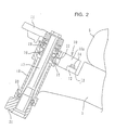
- Fig. 2 is a partially exploded side view of the front portion of the vehicle body;
- Fig. 3 is a plan view of the same part; and
- Fig. 4 is a drawing showing a schematic structure of the steering damper.
- a front fork 2 supporting a front wheel 1 at the lower end thereof is connected to the front portion of a vehicle body frame 3, and is rotatable by a handle 4.
- a fuel tank 5 is supported on the vehicle body frame 3.
- the reference numeral 6 designates a seat
- the numeral 7 designates a rear cowl
- the numeral 8 designates a rear swing arm
- the numeral 9 designates a rear wheel.
- the steering damper 10 is disposed at the central portion of a cross member 12 laid between the front portions of the mainframes 3, 3 branched to the left and right in the vicinity of the upper bracket 11 on which the handle (not shown) is mounted.
- a housing 10a for accommodating the operating portion of the steering damper 10 and the cross member 12 are integrally formed of cast metal or the like, the cross member 12 is formed into a plate shape laterally extending from the housing 10a, and the respective ends of the extended portion are secured to the stepped recesses 13 formed on the upper portion of the mainframe 3 with bolts 14 from above the vehicle body.
- the cross member 12 also serves as a reinforcing member at the front portion of the mainframe 3.
- a sector gear 15 projecting from the housing 10a forwardly of the vehicle body, which engages the drive gear 16.
- the drive gear 16 is integrally mounted around the upper portion of a steering stem 17, and the steering stem 17 passes through the head pipe 18 in the vertical direction, and is rotatably supported by the bearings 19, 20 at the top and bottom of the head pipe 18.
- the upper and lower ends of the steering stem 17 is secured to the upper bracket 11 and the lower bracket 21 located at the upper and lower ends of the head pipe 18.
- the lower bracket 21 is placed substantially in parallel with the upper bracket 11, and supports the front fork 2 together with the upper bracket 11.
- the handle 4, the upper bracket 11, the steering stem 17, the lower bracket 21, and the front fork 2 constitute a steering system, so that when the handle 4 is turned, the upper bracket 11, the steering stem 17, the lower bracket 21 and the front fork 2 turn integrally to steer the front wheel 1.
- the drive gear 16 also turns integrally with the steering stem 17.
- the head pipe 18 is a tubular member connecting the front end portions of the left and right mainframes 3, 3 with each other to constitute the front end portion of the vehicle body frame, and is formed with a opening 22 at the location corresponding to the drive gear 16, through which the teeth of the sector gear 15 inserted into the head pipe 18 engage the drive gear 16.
- Fig. 4 illustrates a structure of the steering damper 10 schematically, showing that a fan-shaped liquid chamber 30 fanning out toward the front is provided within the steering damper 10, and a shaft 31 is rotatably provided at the position corresponding to the linchpin of the fan.
- the portion of the sector gear 15 located within the housing 10a corresponding to the linchpin of the fan is connected to the shaft 31, so that the sector gear 15 and the shaft 31 rotates as a single unit.
- the shaft 31 is also provided integrally with a wing-shaped portion 32 extending forward for dividing the liquid chamber 30, and the wing-shaped portion 32 divides the inside of the liquid chamber 30 into two chambers; the right liquid chamber 33 and the left liquid chamber 34.
- the tip of the wing-shaped portion 32 is formed with a sliding surface, and is brought into sliding contact with the inner surface of the arc-shaped wall 35 of the liquid chamber 30.
- the right liquid chamber 33 and the left liquid chamber 34 are filled with uncompressible liquid such as oil or the like and connected by a by-pass channel 36.
- An adjustable valve 37 is provided at the central portion of the by-pass channel 36.
- the adjustable valve 37 comprises a throttling passage for generating a damping force, and throttle may be varied by changing the sectional area of the throttling passage.
- the adjustable valve 37 employed here is not limited to the type described above, and various types of known adjustable valve may be employed.
- the integrally turning drive gear 16 turns the sector gear 15, and the sector gear 15 in turn turns the shaft 31 integrally.
- the wing-shaped portion32 is turned in the liquid chamber 30 integrally with the shaft 31, and moves as shown in phantom to vary the volume balance between the right liquid chamber 33 and the left liquid chamber 34. Liquid moves the by-pass channel 36 in accordance with variations in volume balance.
- Throttle of the adjustable valve 37 is controlled by a controlling system 38.
- the controlling system 38 is constructed of a microcomputer or the like, and in this embodiment, it controls based on the detected signals of the angular speed sensor 39 and a moment sensor 40. In other words, the value of the angular speed and the rotated direction of the steering stem 17 are obtained by the angular speed detected by the angular speed sensor 39, then the direction of rotating torque applied on the steering stem 17 from the moment detected by the moment sensor 40 is detected, and when these values meet the prescribed conditions, the throttle of the adjustable valve 37 is varied to adjust the damping force to control turning of the steering system 17 at the time of kickback.
- the elements employed by the controlling system 38 as base elements of control are not limited thereto, and various known elements such as a speed of travel or a load on the front wheel as in the aforementioned related art may be employed.
- the steering damper 10 is located at the midsection of the cross member 12 provided between the left and right mainframe 3, 3, and disposed outside the steering system, but not in the steering system. Therefore, when mounting the steering damper 10, changes which should be made to the steering system are only to provide a drive gear 16 around the steering stem 17 and to form an opening 22 on the head pipe 18.
- the cross member 12 In order to perform maintenance of steering damper 10, the cross member 12 must simply be detached from the mainframes 3, 3 by removing the bolts 14, whereby the steering damper 10 and the cross member 12 can be removed together and thus maintenance can be performed separately from the vehicle body. Therefore, since maintenance in a small space is not obliged when performing maintenance, the maintenanceability may be improved.
- the steering damper 10 and the cross member 12 may be attached and detached from above the vehicle body, which further facilitates maintenance of the steering damper 10.
- Fig. 5 is a drawing corresponding to Fig. 2, in which the cross member 12 is mounted on the lower surfaces of the left and right mainframes 3, 3 from below the vehicle body, and the steering damper 10 is mounted on the cross member 12. Therefore, the drive gear 16 and the opening 22 are provided on the lower position of the steering stem 17 and the head pipe 18 respectively.
- the freedom of utilization of the space behind the head pipe 18 increases, and the steering damper 10 and the cross member 12 may be attached and detached from below the vehicle body, thereby facilitating maintenance of the steering damper 10 as in the case of the former embodiment.
- the steering damper 10 cannot be seen from above, the good appearance may be maintained.
- the housing 10a of the steering damper 10 and the cross member 12 separately and mount the housing 10a detachably to the cross member 12 with bolts or the like.
- the steering damper 10 when performing maintenance of the steering damper 10, either it may be removed together with the cross member 12 from the mainframe 3 as in the former embodiment, or only the steering damper 10 may be attached or detached for maintenance without detaching the cross member 12.
- the steering damper 10 and the steering stem 17 are connected by the sector gear 15 and the drive gear 16 in the aforementioned embodiments, it is not limited thereto, and the turning of the steering stem 17 may be transmitted to the steering damper by appropriate means such as a link structure or a lever structure.
- a cross member 12 is laid between the front portions of the mainframes 3, 3 being branched to the left and right from the head pipe 18 so as to extend rearward, and a steering damper 10 is mounted at the center thereof.
- the sector gear 15 is projected frontward from the housing 10a, and the teeth thereof are inserted through the opening 22 formed on the head pipe 18, and are engaged with the drive gear 16 integrally mounted around the steering stem 17 rotatably supported within the head pipe 18.
Landscapes
- Engineering & Computer Science (AREA)
- Mechanical Engineering (AREA)
- Steering Devices For Bicycles And Motorcycles (AREA)
- Cooling, Air Intake And Gas Exhaust, And Fuel Tank Arrangements In Propulsion Units (AREA)
- Fluid-Damping Devices (AREA)
Applications Claiming Priority (2)
| Application Number | Priority Date | Filing Date | Title |
|---|---|---|---|
| JP2001157068A JP4571338B2 (ja) | 2001-05-25 | 2001-05-25 | 車両用ステアリングダンパー装置 |
| JP2001157068 | 2001-05-25 |
Publications (3)
| Publication Number | Publication Date |
|---|---|
| EP1260431A2 true EP1260431A2 (de) | 2002-11-27 |
| EP1260431A3 EP1260431A3 (de) | 2003-10-01 |
| EP1260431B1 EP1260431B1 (de) | 2008-12-24 |
Family
ID=19000989
Family Applications (1)
| Application Number | Title | Priority Date | Filing Date |
|---|---|---|---|
| EP02007920A Expired - Lifetime EP1260431B1 (de) | 2001-05-25 | 2002-04-09 | Fahrzeug mit einem Lenkungsdämpfer |
Country Status (5)
| Country | Link |
|---|---|
| US (1) | US6705631B2 (de) |
| EP (1) | EP1260431B1 (de) |
| JP (1) | JP4571338B2 (de) |
| DE (1) | DE60230469D1 (de) |
| ES (1) | ES2317961T3 (de) |
Cited By (2)
| Publication number | Priority date | Publication date | Assignee | Title |
|---|---|---|---|---|
| EP1759975A3 (de) * | 2005-08-30 | 2008-05-07 | Showa Corporation | Lenkungsdämpfer |
| EP1953076A1 (de) | 2007-01-30 | 2008-08-06 | HONDA MOTOR CO., Ltd. | Im Grätschsitz zu fahrendes Fahrzeug mit Lenkungsdämpfer |
Families Citing this family (10)
| Publication number | Priority date | Publication date | Assignee | Title |
|---|---|---|---|---|
| JP4640905B2 (ja) * | 2001-04-06 | 2011-03-02 | 本田技研工業株式会社 | ステアリングダンパ装置 |
| JP4493066B2 (ja) * | 2001-04-06 | 2010-06-30 | 本田技研工業株式会社 | 自動2輪車用ステアリングダンパ装置 |
| JP4197592B2 (ja) * | 2001-12-28 | 2008-12-17 | 本田技研工業株式会社 | ステアリングダンパ装置 |
| US7789207B2 (en) * | 2002-06-10 | 2010-09-07 | Norman Ralph S | Stabilizer |
| US20050199456A1 (en) * | 2004-03-15 | 2005-09-15 | Norman Ralph S. | Fluidic dampening device |
| US6824153B2 (en) * | 2002-06-21 | 2004-11-30 | Kayaba Industry Co., Ltd. | Steering device |
| JP4545624B2 (ja) * | 2005-03-31 | 2010-09-15 | 本田技研工業株式会社 | ステアリングダンパ取り付け構造 |
| JP5396292B2 (ja) * | 2010-01-21 | 2014-01-22 | 本田技研工業株式会社 | 鞍乗り型車両のステアリングダンパ装置 |
| AR079383A1 (es) | 2010-12-27 | 2012-01-25 | Fischer Hugo Alfredo | Dispositivo estabilizador de direccion para vehiculos con columna y manillar. |
| CN112896401B (zh) * | 2021-03-17 | 2022-07-26 | 浙江春风动力股份有限公司 | 一种摩托车转向系统 |
Citations (2)
| Publication number | Priority date | Publication date | Assignee | Title |
|---|---|---|---|---|
| JPS6364888A (ja) | 1986-09-02 | 1988-03-23 | ギュンター シーア | ステアリング運動の緩衝方法 |
| JPH0774023A (ja) | 1993-09-01 | 1995-03-17 | Hitachi Ltd | 集積化インダクタおよびそれを用いた弾性表面波装置 |
Family Cites Families (11)
| Publication number | Priority date | Publication date | Assignee | Title |
|---|---|---|---|---|
| DE2710651C3 (de) * | 1977-03-11 | 1981-06-25 | Bayerische Motoren Werke AG, 8000 München | Hydraulischer Lenkungsdämpfer für Zweiradfahrzeuge |
| SE8406018D0 (sv) | 1984-11-28 | 1984-11-28 | Hakan Albertsson | Hydrauldempanordning |
| JPS6212473A (ja) * | 1985-07-10 | 1987-01-21 | Honda Motor Co Ltd | ステアリングダンパ− |
| JPH03220077A (ja) * | 1990-01-25 | 1991-09-27 | Suzuki Motor Corp | 自動2輪車のバッテリ保持装置 |
| US5492033A (en) * | 1994-01-03 | 1996-02-20 | Hopey; Timothy C. | Steering damper in and for vehicles |
| JPH07232676A (ja) * | 1994-02-23 | 1995-09-05 | Suzuki Motor Corp | 車両のヘッドライト機構 |
| US5516133A (en) * | 1994-08-04 | 1996-05-14 | Stabletec, Inc. | Steering stabilizer for bicycles |
| DE19508096A1 (de) * | 1995-03-08 | 1996-09-12 | Trw Fahrwerksyst Gmbh & Co | Lenkventil |
| IT237852Y1 (it) * | 1997-08-07 | 2000-09-29 | Crc Ct Ricerche Cagiva S A | Ammortizzatore di sterzo di una motocicletta ad asse costantementeortogonale al piano longitudinale di simmetria del veicolo |
| JP4371180B2 (ja) * | 1999-03-31 | 2009-11-25 | 本田技研工業株式会社 | 自動二輪車の車体フレーム構造 |
| US6471229B2 (en) * | 1999-12-01 | 2002-10-29 | Gary L. Stewart | Bicycle steering dampening apparatus and an apparatus for installing the same |
-
2001
- 2001-05-25 JP JP2001157068A patent/JP4571338B2/ja not_active Expired - Fee Related
-
2002
- 2002-04-09 DE DE60230469T patent/DE60230469D1/de not_active Expired - Lifetime
- 2002-04-09 ES ES02007920T patent/ES2317961T3/es not_active Expired - Lifetime
- 2002-04-09 EP EP02007920A patent/EP1260431B1/de not_active Expired - Lifetime
- 2002-04-23 US US10/127,544 patent/US6705631B2/en not_active Expired - Fee Related
Patent Citations (2)
| Publication number | Priority date | Publication date | Assignee | Title |
|---|---|---|---|---|
| JPS6364888A (ja) | 1986-09-02 | 1988-03-23 | ギュンター シーア | ステアリング運動の緩衝方法 |
| JPH0774023A (ja) | 1993-09-01 | 1995-03-17 | Hitachi Ltd | 集積化インダクタおよびそれを用いた弾性表面波装置 |
Cited By (2)
| Publication number | Priority date | Publication date | Assignee | Title |
|---|---|---|---|---|
| EP1759975A3 (de) * | 2005-08-30 | 2008-05-07 | Showa Corporation | Lenkungsdämpfer |
| EP1953076A1 (de) | 2007-01-30 | 2008-08-06 | HONDA MOTOR CO., Ltd. | Im Grätschsitz zu fahrendes Fahrzeug mit Lenkungsdämpfer |
Also Published As
| Publication number | Publication date |
|---|---|
| US20020175489A1 (en) | 2002-11-28 |
| DE60230469D1 (de) | 2009-02-05 |
| JP4571338B2 (ja) | 2010-10-27 |
| JP2002347684A (ja) | 2002-12-04 |
| EP1260431A3 (de) | 2003-10-01 |
| US6705631B2 (en) | 2004-03-16 |
| ES2317961T3 (es) | 2009-05-01 |
| EP1260431B1 (de) | 2008-12-24 |
Similar Documents
| Publication | Publication Date | Title |
|---|---|---|
| JP4493068B2 (ja) | 鞍乗り型車両用ステアリングダンパ装置 | |
| US9919758B2 (en) | Vehicle | |
| EP0086603B1 (de) | Zweirädrige Fahrzeuge | |
| EP1260431B1 (de) | Fahrzeug mit einem Lenkungsdämpfer | |
| JP2011079343A (ja) | 自動二輪車 | |
| EP1514786B1 (de) | Lenkungsdämpfer für Fahrzeug, und damit ausgestattetes Fahrzeug | |
| EP2781444B1 (de) | Motorrad | |
| JP4467050B2 (ja) | 二輪車用ステアリングダンパ装置 | |
| JP7252335B2 (ja) | リーン車両 | |
| JP5568417B2 (ja) | トラクタ | |
| CA2691500C (en) | Steering damper device for saddle-riding type vehicle | |
| JP2006168548A (ja) | 車両 | |
| JP2021146862A (ja) | 鞍乗り型車両 | |
| JP4080717B2 (ja) | 鞍乗り型車両用ステアリングダンパ装置 | |
| JP4142279B2 (ja) | 鞍乗り型車両用ステアリングダンパ装置 | |
| JP5438352B2 (ja) | 鞍乗り型車両のステアリングダンパ装置 | |
| WO2023139591A1 (en) | Steering system of a vehicle | |
| JP4142291B2 (ja) | ステアリングダンパ装置 | |
| US12257872B2 (en) | Vehicle | |
| JP7623830B2 (ja) | 鞍乗型乗物 | |
| JP3252279B2 (ja) | 動揺均衡補助装置付懸架系をもつ自動車 | |
| JP2977856B2 (ja) | 自動二輪車における前輪懸架装置 | |
| JP2007076634A (ja) | 車両 | |
| JP3898960B2 (ja) | スクータ型自動二輪車の動力ユニット支持装置 | |
| JP4316092B2 (ja) | 走行車輛のフロントアクスル支持構造 |
Legal Events
| Date | Code | Title | Description |
|---|---|---|---|
| PUAI | Public reference made under article 153(3) epc to a published international application that has entered the european phase |
Free format text: ORIGINAL CODE: 0009012 |
|
| AK | Designated contracting states |
Kind code of ref document: A2 Designated state(s): AT BE CH CY DE DK ES FI FR GB GR IE IT LI LU MC NL PT SE TR |
|
| AX | Request for extension of the european patent |
Free format text: AL;LT;LV;MK;RO;SI |
|
| PUAL | Search report despatched |
Free format text: ORIGINAL CODE: 0009013 |
|
| AK | Designated contracting states |
Kind code of ref document: A3 Designated state(s): AT BE CH CY DE DK ES FI FR GB GR IE IT LI LU MC NL PT SE TR |
|
| AX | Request for extension of the european patent |
Extension state: AL LT LV MK RO SI |
|
| 17P | Request for examination filed |
Effective date: 20031118 |
|
| AKX | Designation fees paid |
Designated state(s): DE ES GB IT |
|
| 17Q | First examination report despatched |
Effective date: 20061205 |
|
| RTI1 | Title (correction) |
Free format text: VEHICLE HAVING A STEERING DAMPER SYSTEM |
|
| GRAP | Despatch of communication of intention to grant a patent |
Free format text: ORIGINAL CODE: EPIDOSNIGR1 |
|
| GRAS | Grant fee paid |
Free format text: ORIGINAL CODE: EPIDOSNIGR3 |
|
| GRAA | (expected) grant |
Free format text: ORIGINAL CODE: 0009210 |
|
| AK | Designated contracting states |
Kind code of ref document: B1 Designated state(s): DE ES GB IT |
|
| REG | Reference to a national code |
Ref country code: GB Ref legal event code: FG4D |
|
| REF | Corresponds to: |
Ref document number: 60230469 Country of ref document: DE Date of ref document: 20090205 Kind code of ref document: P |
|
| REG | Reference to a national code |
Ref country code: ES Ref legal event code: FG2A Ref document number: 2317961 Country of ref document: ES Kind code of ref document: T3 |
|
| PLBE | No opposition filed within time limit |
Free format text: ORIGINAL CODE: 0009261 |
|
| STAA | Information on the status of an ep patent application or granted ep patent |
Free format text: STATUS: NO OPPOSITION FILED WITHIN TIME LIMIT |
|
| 26N | No opposition filed |
Effective date: 20090925 |
|
| PGFP | Annual fee paid to national office [announced via postgrant information from national office to epo] |
Ref country code: ES Payment date: 20110518 Year of fee payment: 10 Ref country code: DE Payment date: 20110406 Year of fee payment: 10 |
|
| PGFP | Annual fee paid to national office [announced via postgrant information from national office to epo] |
Ref country code: GB Payment date: 20110406 Year of fee payment: 10 |
|
| PGFP | Annual fee paid to national office [announced via postgrant information from national office to epo] |
Ref country code: IT Payment date: 20110420 Year of fee payment: 10 |
|
| GBPC | Gb: european patent ceased through non-payment of renewal fee |
Effective date: 20120409 |
|
| PG25 | Lapsed in a contracting state [announced via postgrant information from national office to epo] |
Ref country code: GB Free format text: LAPSE BECAUSE OF NON-PAYMENT OF DUE FEES Effective date: 20120409 |
|
| REG | Reference to a national code |
Ref country code: DE Ref legal event code: R119 Ref document number: 60230469 Country of ref document: DE Effective date: 20121101 |
|
| PG25 | Lapsed in a contracting state [announced via postgrant information from national office to epo] |
Ref country code: IT Free format text: LAPSE BECAUSE OF NON-PAYMENT OF DUE FEES Effective date: 20120409 |
|
| REG | Reference to a national code |
Ref country code: ES Ref legal event code: FD2A Effective date: 20131030 |
|
| PG25 | Lapsed in a contracting state [announced via postgrant information from national office to epo] |
Ref country code: ES Free format text: LAPSE BECAUSE OF NON-PAYMENT OF DUE FEES Effective date: 20120410 |
|
| PG25 | Lapsed in a contracting state [announced via postgrant information from national office to epo] |
Ref country code: DE Free format text: LAPSE BECAUSE OF NON-PAYMENT OF DUE FEES Effective date: 20121101 |