EP1253230B2 - Rundstrickmaschine - Google Patents
Rundstrickmaschine Download PDFInfo
- Publication number
- EP1253230B2 EP1253230B2 EP02008445A EP02008445A EP1253230B2 EP 1253230 B2 EP1253230 B2 EP 1253230B2 EP 02008445 A EP02008445 A EP 02008445A EP 02008445 A EP02008445 A EP 02008445A EP 1253230 B2 EP1253230 B2 EP 1253230B2
- Authority
- EP
- European Patent Office
- Prior art keywords
- frame
- circular knitting
- feet
- knitting machine
- foot
- Prior art date
- Legal status (The legal status is an assumption and is not a legal conclusion. Google has not performed a legal analysis and makes no representation as to the accuracy of the status listed.)
- Expired - Lifetime
Links
Images


Classifications
-
- D—TEXTILES; PAPER
- D04—BRAIDING; LACE-MAKING; KNITTING; TRIMMINGS; NON-WOVEN FABRICS
- D04B—KNITTING
- D04B9/00—Circular knitting machines with independently-movable needles
-
- D—TEXTILES; PAPER
- D04—BRAIDING; LACE-MAKING; KNITTING; TRIMMINGS; NON-WOVEN FABRICS
- D04B—KNITTING
- D04B15/00—Details of, or auxiliary devices incorporated in, weft knitting machines, restricted to machines of this kind
-
- D—TEXTILES; PAPER
- D04—BRAIDING; LACE-MAKING; KNITTING; TRIMMINGS; NON-WOVEN FABRICS
- D04B—KNITTING
- D04B15/00—Details of, or auxiliary devices incorporated in, weft knitting machines, restricted to machines of this kind
- D04B15/88—Take-up or draw-off devices for knitting products
-
- D—TEXTILES; PAPER
- D04—BRAIDING; LACE-MAKING; KNITTING; TRIMMINGS; NON-WOVEN FABRICS
- D04B—KNITTING
- D04B35/00—Details of, or auxiliary devices incorporated in, knitting machines, not otherwise provided for
- D04B35/34—Devices for cutting knitted fabrics
Definitions
- the invention relates to a circular knitting machine of the type specified in the preamble of claim 1.
- Circular knitting machines of the type described with such diameters bring both transport and space problems with it. This is mainly due to the fact that their racks are provided with radially projecting feet, which have at the smallest point a machine width of more than 3000 mm (eg 3600 mm) and transverse to it usually an even greater length, if than Width is the smallest parallel to the ground surface and across the length measurable dimension or the smallest diameter of the machine is called.
- Such machines must therefore be transported with police protection on a low loader. For a transport on a low loader without police protection a machine width of at most 3000 mm and for a transport on a usual truck a machine width of maximally 2500 mm would be necessary.
- the technical problem to be solved by the present invention is to design the circular knitting machine of the type described at the outset so that its width can be varied with comparatively inexpensive means and without substantial impairment of the stability.
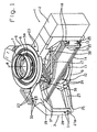
- a circular knitting machine comprises a frame 1, which in the Aus colbrungsbeispiel three spaced at angular intervals of about 120 °, radially from the machine outwardly projecting feet 2 to 4, wherein the foot 2 is a main foot and each of the feet 3 and 4 is a side leg ,
- the HauptfuB 2 serves to receive a drive motor and other electrical or electronic components and other controls of the circular knitting machine, not shown, while the side feet 3, 4 are free of such units except for an optionally existing switch unit.
- the frame 1 further comprises an upper support ring 5, in which a cylinder support ring 6 is rotatably mounted, on which an only schematically indicated Needle support 7 is fixed in the form of a needle cylinder which is rotatably mounted in the frame 1 together with the cylinder support ring 6 about a central axis 8 of the circular knitting machine.
- the support ring 5 is used inter alia for receiving a conventional, the needle carrier 7 surrounding lock shell, of which for the sake of simplicity, only a segment 5a is shown.
- the lower support ring 9 is used for rotatably supporting a turntable 11, on which a frame 12 is fixed, which carries a generally designated by the reference numeral 14 trigger and / or take-up device, by means of which one of the needle carrier 7, only in Fig. 3 indicated knitted fabric 15 can be removed and wound up. It is in principle indifferent whether the knitted fabric 15 only deducted from the trigger and / or reeling device 14, only wound and / or withdrawn and wound up, as is well known in the art.
- the frame 12 includes in an upper portion two fixed or rotatably mounted deflecting rods 16, in a section immediately below two rotatably mounted, preferably substantially horizontally and V-shaped arranged to spread the knitted fabric rollers 17, below these and in a middle part of the frame 1 two or more, in turn with the rollers 17 rotatable and rotating take-off rollers 18 and in a lower portion finally a loosely rotatably mounted in the frame 12 take-up roller 19 which is associated with at least one, adjacent to its periphery drive roller 20, to wind the knitted fabric 15 supplied by the take-off rolls 18 during operation of the circular knitting machine in a known manner onto the take-up roll 19.
- the circular knitting machine mounted in the frame 1, rotatable knife 21 ( Fig. 3 ), which serves the purpose of cutting the coming from the needle carrier 7 knitted fabric 15 after passing through a broader, not shown, and the deflection bars 16 along a side line.
- the knife 21 is preferably slidable on a rod 21a to allow adaptation to different fabric widths.
- the rollers 17 may alternatively stand still or rotate and possibly be driven by means of a separate rotary drive independent of the take-off rollers 18.
- the frame 1 by screws 23, the upper ends of the feet 2 to 4 connect to the upper support ring 5, and screws 24, the lower ends of the feet 2 to 4 connect to the lower support ring 9, assembled into a mechanically strong assembly which absorbs all forces and moments occurring during operation of the circular knitting machine and is preferably supported on adjustable adjusting elements 25 projecting downwards from the underside of the feet 2 to 4.
- Circular knitting machines of this type are generally known and therefore need not be explained in greater detail to the person skilled in the art ( DE-T2 691 21 291 . US-A-5 566 558 . WO-A-00/506 78 ).
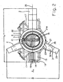
- the frame 1 has at least one adjustable foot, by means of which the width B (FIG. Fig. 2 ) of the described circular knitting machine can be changed.
- the width B (FIG. Fig. 2 ) of the described circular knitting machine can be changed.
- Such a change is z. B. required when a door through which the circular knitting machine must be transported, has a clear width, which is smaller than the smallest, measured parallel to the ground dimension of the circular knitting machine.
- the required width of a loading area of a truck or the like depends on the smallest width of the circular knitting machine in any direction, while the length measured transversely thereto is usually insignificant.
- the breadth B of a circular knitting machine is understood here to illustrate the invention here a measure that corresponds approximately to the distance between the radially outermost points of the side feet 3, 4 from each other and transverse to a length L.
- the length L is z. B. measured in the direction of a longitudinal axis 26 which extends approximately through a vertical, the central axis 8 enclosing center plane of the main foot and in the embodiment is greater than the width B.
- other dimensions may be referred to as the "width" of the circular knitting machine.
- the side leg 3 includes at its lower end a first bottom brace 27, at its upper end a central piece 28 and between both a support 29, wherein in the assembled state, both the bottom brace 27 and the middle piece 28 substantially radially and horizontally aligned, the support 29th in contrast, is arranged substantially vertically.
- the bottom strut 27 and the intermediate piece 28 are at radially inner ends by means of screws 23, 24 on the upper and lower support ring 5 and 9 and at radially outer ends by means of further screws 30, 31 at the upper and lower end of the support 29th attached.
- the adjusting elements 25 are below the support by means of threaded parts rotatably attached to the bottom brace 27, to which the support 29 and / or the bottom brace 27 may be provided with corresponding threaded parts, and can be adjusted by turning so that the circular knitting machine is leveled during normal operation exactly.
- the bottom strut 27 is provided at its radially outer end with a step 27a intended to support the support 29.
- the side foot 4 is designed in the same way as the side foot 3.
- the main foot 2 is preferably formed substantially in the manner of a cabinet to accommodate the various components and controls in him. It also shows in particular Fig. 2 in that all three feet 2, 3 and 4 protrude radially so far beyond the remaining parts of the circular knitting machine that an imagined outer circle touches only the outer tips of the feet 2, 3 and 4 and not shown within this enveloping circle on the side surfaces of the Feet 2, 3 and 4 attachable grille, doors and the like. Can be releasably attached.
- a change in the width B can be brought about by the fact that the frame 1, on the one hand, two bottom braces 27 and 32 of different lengths for the foot 3 (FIGS. Fig. 4 ) are assigned, so that this can be selectively connected by means of the first bottom strut 27 or by means of the second bottom strut 32 with the lower part of the frame 1.
- the supports 29 and the intermediate piece 28 are formed so that the foot 3 can be fixed at the upper end either by means of the intermediate piece 28 or directly to the upper part of the frame 1.
- Show Fig. 1 and 2 the attachment by means of the intermediate piece 28 and the first, long floor strut 27 and Fig. 4 and 5 the attachment without the intermediate piece 28 and with the second, short floor brace 32.
- the second floor brace 32 also designed so that it with the same screws 24, 31 as the first bottom brace 27 on the lower support ring 9 and at the lower end of the Support 29 can be attached.
- the second bottom brace 32 is also provided at its radially outer end with a step 27a corresponding stage 32a.
- the upper end of the support 29 is preferably formed as well as the radially inner end of the intermediate piece 28 so that it, as Fig. 1 and 4 show, omitting the intermediate piece 28 in the same way as this can be fixed by means of the screws 23 on the upper support ring 5.
- the relative lengths of the intermediate piece 28 and the bottom struts 27, 32 are chosen so that the support 29 of the foot 3 in both the arrangement according to Fig. 1 and 2 as well as at the Fig. 4 and 5 essentially occupying the same vertical position.
- the frame 1 is an auxiliary support 33 ( Fig. 4 ), which preferably has two arms 33a, 33b angled at 90 ° at their ends.
- the distance of the outer surfaces of the two arms 33a, 33b is slightly smaller than the clear distance of the upper support ring 5 from the lower support ring 9. It is therefore possible, the two arms 33a, 33b from the outside radially into a between the support rings 5, 9 existing Insert space and then attach to the frame 1.
- the arm 33a has a screw hole to which a threaded hole formed in the lower support ring 9 is assigned, while the arm 33b has a threaded bore with a set screw 34 inserted in it. It is then possible, the auxiliary support 33 first in the off Fig.
- the side leg 4 is preferably, but not necessarily, as well as the side leg 3 is formed and radially adjustable with one spacer 28, two bottom struts 27 and 32 and an associated auxiliary support 33.
- a change in machine width (dimension B in Fig. 2 ) of an in Fig. 4 and 5 shown transport position in a Fig. 1 to 3 apparent operating position can, if necessary, after previous dismantling of protective screens, not shown, od.
- z. B be made as follows:
- the auxiliary feet 10 arranged in the region of the feet 3 and 4 are unscrewed so far that the lower support ring 9 is firmly supported on them. Subsequently, the auxiliary support 33 is brought into position and clamped by means of screws 34, 35 fixed between the upper and lower support ring 5, 9, so that they are now fixed by the auxiliary support 33 and kept at a distance.
- a squared timber is now placed on the ground strut 27 and under the underside of the support 29, at a location located between the step 27a and the lower support ring 9. Thereafter, the screws 23 are loosened and unscrewed at the upper support ring 5, whereby the support 29 comes to rest on the squared timber and is suitably held by an assistant. It is now possible, the prop 29 on the squared timber radially outward in their off Fig. 1 apparent operating position, which is determined by the position of the step 27a and formed in this screw holes. Subsequently, the support 29 is fastened at its lower end by means of the screws 31 to the bottom strut 27.
- the second side foot 4 is also located in a transport position Fig. 4 and 5 , It is brought into the operating position in a corresponding manner, as described above for the side foot 3.
- the frame 1 is leveled by means of the adjusting elements 25, on the one hand, the auxiliary support 33 is removed, on the other hand, the auxiliary feet 10 can be rotated back inside, so that the frame 1 and with him the entire circular knitting machine now alone on the Feet 2 to 4 is supported.
- the auxiliary feet 10 can of course also be used as additional supports for the lower support ring 9.
- the minimum width after arrangement of the feet 3, 4 in the transport position may well be less than B ', as in FIG Fig. 5 by a transversely, but obliquely to the longitudinal axis 26 detected measure B "is indicated.
- a significant advantage is that the feet 2, 3 and 4 in the operating position after Fig. 2 - Viewed in the circumferential direction - comparatively large angular distances of z. B. 130 ° between the side feet 3, 4 on the one hand and z. B. each have 115 ° between them and the main foot 2 on the other hand.
- a high level of stability during operation is possible.
- auxiliary support (s) 33 forms a bending and torsion-resistant structural unit and therefore at least temporarily can be operated in this state. It is therefore possible to mount the circular knitting machine in the factory first with the help of the auxiliary support 33 and located in transport position feet 3 and 4 and set up and bring the feet 3, 4 only after delivery to the customer in the operating position. In this case, however, instead of the comparatively long withdrawal and Aufwicklungswalzen 18, 19, however, other relatively short withdrawal and Aufwickelwalzen be used, with which the knitted fabric 15 can be pulled off and wound up as a hose and without the auxiliary support 33 this process with special needs. It is also advantageous that the additional parts needed 32 and 33 are relatively inexpensive to produce.
- the invention also provides several advantageous options. It is Z. B. possible to choose the angular distance of the feet 3, 4 so large that in their operating position for winding up a spread knitted fabric 15 certain take-up roller 19 can easily remove even in the fully filled state from the frame 1, wherein the axis of the take-up roller 19th perpendicular to the longitudinal axis 26 in Fig. 2 can be arranged. Further, the arrangement is preferably such that the machine width is variable even when mounted in the frame 1 trigger and / or reeling device 14, in particular when the axes of the trigger and / or take-up rollers 18, 19 in this case accordingly Fig. 4 and 5 are arranged substantially parallel to the longitudinal axis 26.
- At least one driver 37 is provided in the embodiment with the underside of the cylinder support ring 6, which serves for the synchronous rotation of the frame 12 with the cylinder support ring 6 and optionally in two by 90 ° on the frame 12 spaced coupling receptacles 38 can be hung.
- the arrangement is such that the circular knitting machine is operable with the feet 3, 4 in transport position, at least with the deduction and / or winding device suitable for a closed tubular fabric. This makes it possible to carry out all the work required for the setup of the circular knitting machine in the transport position of the frame 1 which occupies a comparatively small space and to assemble the withdrawal and / or winding device 14 suitable for a spread knitted fabric 15 only after this or even only at the customer.
- the foot 3 and / or 4 it is possible to form the foot 3 and / or 4 as a whole radially adjustable by z. B. is mounted radially displaceable on the frame 1 or by the bottom strut 27 and the intermediate piece 28 are made of two relatively displaceable parts.
- Another possibility is to pivot the foot 3 and / or 4 to arrange by z. B. to a central axis 8 ( Fig. 1 ) parallel, in the region of the screws 23, 24 provided pivot axis is pivotally mounted.
- the invention can be further applied to racks having more than three feet and, if necessary, an adjustable main foot 2.
- the invention is not limited to the described diameter and angle specifications, which have been given only by way of example.
- the needle carrier 7 could instead be designed as a needle cylinder as a dial or in addition to the needle cylinder also contain a dial.
Landscapes
- Engineering & Computer Science (AREA)
- Textile Engineering (AREA)
- Knitting Machines (AREA)
Description
- Die Erfindung betrifft eine Rundstrickmaschine der im Oberbegriff des Anspruchs 1 angegebenen Gattung.
- Bei Rundstrickmaschinen dieser Art mit Nadelzylinderdurchmessern von z. B. 26" bis 30" und größer besteht häufig das Bedürfnis, die Abzugs- und/oder Aufwickelvorrichtung so auszusbilden, daß nicht die aus der Maschine kommende, geschlossene Schlauchware, sondern ein an einer Längsseite aufgeschnittener und dann auf die doppelte Breite ausgebreiteter Stoff aufgewickelt wird (
DE-T2-0 691 21 291 ,US-A-5 566 558 ,WO-A-00/50678 - Rundstrickmaschinen der eingangs bezeichneten Gattung mit derartigen Durchmessern bringen sowohl Transport- als auch Platzprobleme mit sich. Das ist vor allem eine Folge davon, daß ihre Gestelle mit radial vorstehenden Füßen versehen sind, die an der kleinsten Stelle eine Maschinenbreite von mehr als 3000 mm (z. B. 3600 mm) und quer dazu meistens eine noch größere Länge besitzen, wenn als Breite die kleinste parallel zur Erdbodenoberfläche und quer zur Länge messbare Dimension bzw. der kleinste Durchmesser der Maschine bezeichnet wird. Derartige Maschinen müssen daher mit Polizeischutz auf einem Tieflader transportiert werden. Für einen Transport auf einem Tieflader ohne Polizeischutz wäre eine Maschinenbreite von höchstens 3000 mm und für einen Transport auf einem üblichen Lastkraftwagen eine Maschinenbreite von höchstens 2500 mm erforderlich. Nicht unbeachtlich ist außerdem der Umstand, daß die Werkhallen sowohl beim Hersteller als auch beim Anwender meistens Türen und/oder Aufzüge mit lichten Weiten besitzen, die kleiner als 3600 mm sind. Schließlich besteht insbesondere beim Hersteller, wo in der Regel zahlreiche Rundstrickmaschinen nebeneinander in derselben Werkhalle für die spätere Benutzung beim Anwender eingerichtet werden, ein erheblicher Bedarf an Maschinen, die einen möglichst geringen Platzbedarf haben und vor allem eine möglichst geringe Breite besitzen.
- Zur Beseitigung dieser Probleme werden von den Maschinenherstellern unterschiedliche Lösungen vorgeschlagen, die sämtlich nicht voll befriedigen. So ist es z. B. bekannt, einen der Füße des Gestells zum Transport der Maschine völlig zu entfernen und gegebenenfalls durch einen speziellen Hilfsfuß zu ersetzen. Das verursacht entweder unerwünschte Zusatzkosten oder behindert sowohl den Transport als auch den Umbau, da hierfür zusätzliche Holzunterbauten und/oder Gabelstapler od. dgl. benötigt werden. Bekannt ist es ferner, die in der Regel drei vorhandenen Füße nicht in gleichen Abständen von ca. 120° anzuordnen, sondern zwei Füße mit wesentlich größeren Abständen relativ zum dritten Fuß zu montieren, so daß diese beiden Füße zwar einerseits eng nebeneinander stehen und dadurch die Maschinenbreite reduzieren, andererseits aber auch eine erheblich verringerte Standfestigkeit des Maschinengestells verursachen.
- Angesichts dieses Standes der Technik besteht das von der vorliegenden Erfindung zu lösende technische Problem darin, die Rundstrickmaschine der eingangs bezeichneten Gattung so auszubilden, daß ihre Breite mit vergleichsweise kostengünstigen Mitteln und ohne wesentliche Beeinträchtigung der Standsicherheit verändert werden kann.
- Aus "Knittting International", No. 1270, Mai 2000, S. 24-25, Artikel "Solving the centre crease problem" und Werbungsseite ist ein Umbau-Kit namens Codematex Kit bekannt, mit dem eine Rundstrickmaschine mit einer Abzugseinrichtung für Schlauchware in eine Rundstrickmaschine für aufgeschnittene Schlauchware umgebaut werden kann. Zum Einbau der breiteren Abzugs- und Aufwickeleinrichtung für Schlauchware werden die Füße der Maschine zumindest teilweise durch Einsatz von Zwischenstücken radial nach außen versetzt.
- Zur Lösung dieses Problems dienen die kennzeichnenden Merkmale des Anspruchs 1.
- Weitere vorteilhafte Merkmale der Erfindung ergeben sich aus den Unteransprüchen.
- Die Erfindung wird nachfolgend in Verbindung mit den beiliegenden Zeichnungen an einem Ausführungsbeispiel näher erläutert. Es zeigen:
-
Fig. 1 eine schematische perspektivische Darstellung einer Rundstrickmaschine in einem Betriebszustand; -
Fig. 2 eine Draufsicht auf die Rundstrickmaschine nachFig. 1 ; -
Fig. 3 eine Seitenansicht der Rundstrickmaschine in Richtung eines Pfeils x inFig. 2 ; -
Fig. 4 eine derFig. 1 entsprechende Darstellung der Rundstrickmaschine in einem Transportzustand mit zwei zu dessen Herstellung demontierbaren Bauteilen; und -
Fig. 5 eine Draufsicht auf die Rundstrickmaschine nachFig. 4 . - Nach
Fig. 1 bis 3 enthält eine Rundstrickmaschine ein Gestell 1, das im Ausfübrungsbeispiel drei in Winkelabständen von je ca. 120° beabstandete, radial von der Maschine nach außen abstehende Füße 2 bis 4 aufweist, wobei der Fuß 2 ein Hauptfuß und jeder der Füße 3 und 4 ein Seitenfuß ist. Der HauptfuB 2 dient der Aufnahme eines nicht näher dargestellten Antriebsmotors und sonstiger elektrischer bzw. elektronischer Baugruppen sowie von Bedienelementen für die Rundstrickmaschine, während die Seitenfüße 3, 4 bis auf eine gegebenenfalls vorhandene Schaltereinheit frei von derartigen Baueinheiten sind. - Das Gestell 1 weist weiterhin einen oberen Tragring 5 auf, in dem ein Zylindertragring 6 drehbar gelagert ist, auf dem ein nur schematisch angedeuteter Nadelträger 7 in Form eines Nadelzylinders befestigt ist, der zusammen mit dem Zylindertragring 6 um eine Mittelachse 8 der Rundstrickmaschine drehbar im Gestell 1 gelagert ist. Der Tragring 5 dient u. a. zur Aufnahme eines üblichen, den Nadelträger 7 umgebenden Schloßmantels, von dem der Einfachheit halber nur ein Segment 5a dargestellt ist. Außerdem weist das Gestell 1 einen unteren Tragring 9 auf, der mit Hilfe von drehbaren und in der Höhe verstellbaren, an seiner Unterseite befestigten Hilfsfüßen 10 auf dem Boden abgestellt werden kann. Der untere Tragring 9 dient zur drehbaren Lagerung eines Drehtellers 11, auf dem ein Rahmen 12 befestigt ist, der eine allgemein mit dem Bezugszeichen 14 bezeichnete Abzugs- und/oder Aufwickelvorrichtung trägt, mittels derer eine vom Nadelträger 7 hergestellte, nur in
Fig. 3 angedeutete Strickware 15 abgezogen und aufgewickelt werden kann. Dabei ist es im Prinzip gleichgültig, ob die Strickware 15 von der Abzugs- und/oder Aufwickelvorrichtung 14 nur abgezogen, nur aufgewickelt und/oder abgezogen und aufgewickelt wird, wie dem Fachmann allgemein bekannt ist. - Im Ausführungsbeispiel enthält der Rahmen 12 in einem oberen Abschnitt zwei fest oder drehbar gelagerte Umlenkstangen 16, in einem unmittelbar darunter befindlichen Abschnitt zwei drehbar gelagerte, vorzugsweise im wesentlichen horizontal und V-förmig angeordnete, zur Ausbreitung der Strickware bestimmte Walzen 17, unterhalb von diesen und in einem mittleren Teil des Gestells 1 zwei oder mehr, synchron mit den Walzen 17 drehbare und umlaufende Abzugswalzen 18 und in einem unteren Abschnitt schließlich eine lose drehbar im Rahmen 12 gelagerte Aufwickelwalze 19, der wenigstens eine, an ihrem Umfang anliegende Antriebswalze 20 zugeordnet ist, um die beim Betrieb der Rundstrickmaschine von den Abzugswalzen 18 gelieferte Strickware 15 in bekannter Weise auf die Aufwickelwalze 19 aufzuwickeln. Schließlich weist die Rundstrickmaschine ein im Gestell 1 montiertes, drehbares Messer 21 (
Fig. 3 ) auf, das dem Zweck dient, die vom Nadelträger 7 kommende Strickware 15 nach dem Passieren eines nicht dargestellten Breithalters sowie der Umlenkstangen 16 längs einer Seitenlinie aufzuschneiden. Das Messer 21 ist vorzugsweise auf einer Stange 21a verschiebbar, um eine Anpassung an verschiedene Stoffbreiten zu ermöglichen. Die Walzen 17 können alternativ stillstehen oder sich drehen und ggf. mit Hilfe eines separaten Drehantriebs unabhängig von den Abzugswalzen 18 angetrieben sein. - Beim Betrieb der Rundstrickmaschine wird die vom Nadelträger 7 kommende Strickware 15 mittels der V-Walzen 17 längs der Schnittlinie ausgebreitet, bis sie eine einlagige, im wesentlichen ebene Bahn bildet, und dann mit Hilfe einer drehbar im Gestell 1 gelagerten Umlenkwalze 22 (
Fig. 2 und3 ) den Abzugswalzen 18 und von dort der Aufwickelwalze 19 zugeführt. Sie wird dann von dieser mit einer Breite aufgewickelt, die der doppelten Breite der mit dem Nadelträger 7 produzierten und normalerweise an gegenüberliegenden Seitenkanten gefalteten, zweilagigen Schlauchware entspricht. Dabei ist gleichgültig, ob der Nadelträger 7 und mit ihm die gesamte Abzugs- und Aufwickelvorrichtung 14 mit Hilfe des im Hauptfuß 2 untergebrachten Antriebs um die Mittelachse 8 rotiert oder ob beide im Stillstand verbleiben und stattdessen der Schloßmantel in Umdrehungen versetzt wird. - Im übrigen ist das Gestell 1 durch Schrauben 23, die obere Enden der Füße 2 bis 4 mit dem oberen Tragring 5 verbinden, und Schrauben 24, die untere Enden der Füße 2 bis 4 mit dem unteren Tragring 9 verbinden, zu einer mechanisch festen Baueinheit zusammengesetzt, die alle beim Betrieb der Rundstrickmaschine auftretenden Kräfte und Momente aufnimmt und vorzugsweise auf von der Unterseite der Füße 2 bis 4 nach unten abstehenden, einstellbaren Stellelementen 25 abgestützt ist.
- Rundstrickmaschinen dieser Art sind allgemein bekannt und brauchen daher dem Fachmann nicht näher erläutert werden (
DE-T2 691 21 291 ,US-A-5 566 558 ,WO-A-00/506 78 - Erfindungsgemäß weist das Gestell 1 wenigstens einen verstellbaren Fuß auf, mittels dessen die Breite B (
Fig. 2 ) der beschriebenen Rundstrickmaschine geändert werden kann. Eine derartige Änderung ist z. B. erforderlich, wenn eine Tür, durch die die Rundstrickmaschine transportiert werden muß, eine lichte Weite besitzt, die kleiner als die kleinste, parallel zum Erdboden gemessene Dimension der Rundstrickmaschine ist. Entsprechend hängt die erforderliche Breite einer Ladefläche eines Lastkraftwagens od. dgl. von der kleinsten Breite der Rundstrickmaschine in irgendeiner Richtung ab, während die quer dazu gemessene Länge meistens unbedeutend ist. Unter der Breite B einer Rundstrickmaschine wird zur Erläuterung der Erfindung hier ein Maß verstanden, das etwa dem Abstand der radial am weitesten außen liegenden Punkte der Seitenfüße 3, 4 voneinander und quer zu einer Länge L entspricht. Die Länge L wird dabei z. B. in Richtung einer Längsachse 26 gemessen, die etwa durch eine vertikale, die Mittelachse 8 einschließende Mittelebene des Hauptfußes verläuft und im Ausführungsbeispiel größer als die Breite B ist. Je nach Fall können auch andere Maße als "Breite" der Rundstrickmaschine bezeichnet werden. - Nach
Fig. 1 und2 enthält der Seitenfuß 3 an seinem unteren Ende eine erste Bodenstrebe 27, an seinem oberen Ende ein Mittelstück 28 und zwischen beiden eine Stütze 29, wobei im montierten Zustand sowohl die Bodenstrebe 27 als auch das Mittelstück 28 im wesentlichen radial und horizontal ausgerichtet, die Stütze 29 dagegen im wesentlichen vertikal angeordnet ist. Die Bodenstrebe 27 und das Zwischenstück 28 sind an radial innen liegenden Enden mittels der Schrauben 23, 24 am oberen bzw. unteren Tragring 5 bzw. 9 und an radial außen liegenden Enden mittels weiterer Schrauben 30, 31 am oberen bzw. unteren Ende der Stütze 29 befestigt. Die Stellelemente 25 sind unterhalb der Stütze mit Hilfe von Gewindeteilen drehbar an der Bodenstrebe 27 befestigt, wozu die Stütze 29 und/oder die Bodenstrebe 27 mit entsprechenden Gewindeteilen versehen sein kann, und können durch Drehen so eingestellt werden, daß die Rundstrickmaschine beim normalen Betrieb exakt nivelliert ist. Außerdem zeigen insbesondereFig. 1 und4 , daß die Bodenstrebe 27 an ihrem radial äußeren Ende mit einer zur Abstützung der Stütze 29 bestimmten Stufe 27a versehen ist. - Nach einer bevorzugten Ausführungsform der Erfindung ist der Seitenfuß 4 genauso wie der Seitenfuß 3 ausgebildet. Dagegen ist der Hauptfuß 2 vorzugsweise im wesentlichen nach Art eines Schaltschranks ausgebildet, um die verschiedenen Baugruppen und Bedienelemente in ihm unterzubringen können. Außerdem zeigt insbesondere
Fig. 2 , daß alle drei Füße 2, 3 und 4 radial so weit über die übrigen Teile der Rundstrickmaschine nach außen vorstehen, daß ein gedachter Hüllkreis nur die äußeren Spitzen der Füße 2, 3 und 4 berührt und innerhalb dieses Hüllkreises nicht dargestellte, an den Seitenflächen der Füße 2, 3 und 4 befestigbare Schutzgitter, Türen und dgl. lösbar angebracht werden können. Diese werden in bekannter Weise beim Betrieb der Rundstrickmaschine zwischen dem oberen und unteren Tragring 5, 9 montiert, um unbeabsichtigte Verletzungen des Bedienungspersonals durch die rotierende Abzugs- und/oder Aufwickelvorrichtung 14 oder andere rotierende Teile zu verhindern. Die Maße B und L inFig. 2 sind daher durch die radialen Abstände der Füße 2, 3 und 4 bzw. deren Stützen 29 von der Mittelachse 8 festgelegt. - Eine Veränderung der Breite B kann dadurch herbeigeführt werden, daß dem Gestell 1 einerseits zwei unterschiedlich lange Bodenstreben 27 und 32 für den Fuß 3 (
Fig. 4 ) zugeordnet sind, so daß dieser wahlweise mittels der ersten Bodenstrebe 27 oder mittels der zweiten Bodenstrebe 32 mit dem unteren Teil des Gestells 1 verbunden werden kann. Andererseits sind die Stützen 29 und das Zwischenstück 28 so ausgebildet, daß der Fuß 3 am oberen Ende wahlweise mittels des Zwischenstücks 28 oder direkt am oberen Teil des Gestells 1 befestigt werden kann. Dabei zeigenFig. 1 und2 die Befestigung mittels des Zwischenstücks 28 und der ersten, langen Bodenstrebe 27 undFig. 4 und5 die Befestigung ohne das Zwischenstück 28 und mit der zweiten, kurzen Bodenstrebe 32. Mit besonderem Vorteil ist die zweite Bodenstrebe 32 außerdem so ausgebildet, daß sie mit denselben Schrauben 24, 31 wie die erste Bodenstrebe 27 am unteren Tragring 9 bzw. am unteren Ende der Stütze 29 befestigt werden kann. Die zweite Bodenstrebe 32 ist außerdem an ihrem radial äußeren Ende mit einer der Stufe 27a entsprechenden Stufe 32a versehen. Schließlich ist das obere Ende der Stütze 29 vorzugsweise genau so wie das radial innere Ende des Zwischenstücks 28 ausgebildet, so daß es, wieFig. 1 und4 zeigen, beim Weglassen des Zwischenstücks 28 in derselben Weise wie dieses mittels der Schrauben 23 am oberen Tragring 5 befestigt werden kann. Im übrigen sind die relativen Längen des Zwischenstücks 28 und der Bodenstreben 27, 32 so gewählt, daß die Stütze 29 des Fußes 3 sowohl bei der Anordnung nachFig. 1 und2 als auch bei der nachFig. 4 und5 im wesentlichen die gleiche vertikale Lage einnimmt. - Schließlich ist dem Gestell 1 eine Hilfsstütze 33 (
Fig. 4 ) zugeordnet, die an ihren Enden vorzugsweise zwei um 90° abgewinkelte Arme 33a, 33b aufweist. Der Abstand der Außenflächen der beiden Arme 33a, 33b ist etwas kleiner als der lichte Abstand des oberen Tragrings 5 vom unteren Tragring 9. Es ist daher möglich, die beiden Arme 33a, 33b von außen her radial in einen zwischen den Tragringen 5, 9 bestehenden Zwischenraum einzusetzen und dann am Gestell 1 zu befestigen. Zu diesem Zweck weist der Arm 33a ein Schraubloch auf, dem eine im unteren Tragring 9 ausgebildete Gewindebohrung zugeordnet ist, während der Arm 33b eine Gewindebohrung mit einer in sie eingesetzten Stellschraube 34 aufweist. Es ist dann möglich, die Hilfsstütze 33 zunächst in die ausFig. 4 ersichtliche Position zu bringen, dann mittels einer durch das Schraubloch des Arms 33a in die Gewindebohrung des unteren Tragrings 9 eingedrehte Befestigungsschraube 35 an diesem zu befestigen und anschließend durch Festziehen der Stellschraube 34 zwischen der Unterseite des oberen Tragrings 5 und der Oberseite des unteren Tragrings 9 zu verspannen. Die Anordnung ist dabei zweckmäßig so, daß die Hilfsstütze 33 in Umfangsrichtung der Tragringe 5, 9 unmittelbar dort positioniert und befestigt werden kann, wo sich der Fuß 3 befindet. - Der Seitenfuß 4 ist vorzugsweise, aber nicht notwendigerweise, genauso wie der Seitenfuß 3 ausgebildet und mit je einem Zwischenstück 28, zwei Bodenstreben 27 und 32 und einer zugeordneten Hilfsstütze 33 radial verstellbar.
- Eine Änderung der Maschinenbreite (Maß B in
Fig. 2 ) von einer inFig. 4 und5 gezeigten Transportstellung in eine ausFig. 1 bis 3 ersichtliche Betriebsstellung kann, gegebenenfalls nach vorheriger Demontage von nicht dargestellten Schutzgittern od. dgl., z. B. wie folgt vorgenommen werden: - Es werden zunächst die im Bereich der Füße 3 und 4 angeordneten Hilfsfüße 10 so weit herausgedreht, daß der untere Tragring 9 fest auf diesen abgestützt ist. Anschließend wird die Hilfsstütze 33 in Stellung gebracht und mittels der Schrauben 34, 35 fest zwischen dem oberen und unteren Tragring 5, 9 verspannt, so daß diese jetzt durch die Hilfsstütze 33 fixiert und auf Abstand gehalten werden. Anschließend werden die Schrauben 24, 31 am unteren Tragring 9 bzw. am unteren Ende der Stütze 29 gelöst und herausgedreht, worauf die kurze Bodenstrebe 32 entfernt und durch die lange Bodenstrebe 27 ersetzt wird, die daraufhin mittels der Schrauben 24 am unteren Tragring 9 befestigt wird. Der obere Tragring 5 ist während dieser Zeit mittels der Hilfsstütze 33 auf dem unteren Tragring 9 abgestützt, so daß sich das Gestell 1 nicht verwinden kann.
- Vorzugsweise wird nun ein Kantholz auf die Bodenstrebe 27 und unter die Unterseite der Stütze 29 gelegt, und zwar an einer zwischen der Stufe 27a und dem unteren Tragring 9 befindlichen Stelle. Danach werden die Schrauben 23 am oberen Tragring 5 gelöst und herausgedreht, wodurch die Stütze 29 auf dem Kantholz zu liegen kommt und dabei zweckmäßig durch eine Hilfsperson gehalten wird. Es ist nun möglich, die Stütze 29 auf dem Kantholz radial nach außen in ihre aus
Fig. 1 ersichtliche Betriebsstellung zu ziehen, die durch die Lage der Stufe 27a und in dieser ausgebildete Schraublöcher vorgegeben ist. Anschließend wird die Stütze 29 an ihrem unteren Ende mittels der Schrauben 31 an der Bodenstrebe 27 befestigt. - Abschließend wird das Zwischenstück 28 in der aus
Fig. 1 und4 ersichtlichen Weise auf das obere Ende der Stütze 29 und den oberen Tragring 5 aufgelegt und einerseits mittels der Schrauben 23 am oberen Tragring 5, andererseits mittels der Schrauben 30 an der Stütze 29 befestigt. Der Fuß 3 nimmt nun seine Betriebsstellung ein. - Befindet sich auch der zweite Seitenfuß 4 in einer Transportstellung nach
Fig. 4 und5 , wird er auf entsprechende Weise, wie oben für den Seitenfuß 3 beschrieben wurde, in die Betriebsstellung gebracht. - Nach dem Festziehen aller Schrauben wird das Gestell 1 mit Hilfe der Stellelemente 25 nivelliert, worauf einerseits die Hilfsstütze 33 entfernt wird, andererseits die Hilfsfüße 10 wieder nach innen gedreht werden können, so daß das Gestell 1 und mit ihm die gesamte Rundstrickmaschine jetzt allein auf den Füßen 2 bis 4 abgestützt ist. Dabei können die Hilfsfüße 10 natürlich auch als zusätzliche Stützen für den unteren Tragring 9 verwendet werden.
- Wie ein Vergleich der
Fig. 2 und5 zeigt, ist das in der Transportstellung der Füße 3, 4 erhaltene Maß B' inFig. 5 deutlich kleiner als das in der Betriebsstellung der Füße 3, 4 erhaltene Maß B inFig. 2 . Soll die entsprechendFig. 1 bis 3 aufgestellte Rundstrickmaschine daher aus irgendeinem Grund an einen anderen Ort verbracht und dabei aus Transportgründen mit einer Breite versehen werden, die kleiner als das Maß B ist, braucht lediglich der eine und/oder der andere Seitenfuß 3, 4 in die ausFig. 5 ersichtliche Transportstellung gebracht werden, indem die oben erläuterten Schritte in umgekehrter Reihenfolge durchgeführt werden. Dabei versteht sich, daß die minimale Maschinenbreite nicht unbedingt dem senkrecht zur Längsrichtung 26 gemessenen Maß B' inFig. 5 entsprechen muß. Je nach Zahl und Lage der Füße 2, 3 und 4 kann vielmehr die minimale Breite nach Anordnung der Füße 3, 4 in der Transportstellung durchaus auch kleiner als B' sein, wie inFig. 5 durch ein zwar quer, aber schräg zur Längsachse 26 ermitteltes Maß B" angedeutet ist. - Ein wesentlicher Vorteil besteht darin, daß die Füße 2, 3 und 4 in der Betriebsstellung nach
Fig. 2 - in Umfangsrichtung betrachtet - vergleichsweise große Winkelabstände von z. B. 130° zwischen den Seitenfüßen 3, 4 einerseits und z. B. je 115° zwischen diesen und dem Hauptfuß 2 andererseits aufweisen können. Trotz der zum Transport möglichen Reduzierbarkeit der Maschinenbreite wird dadurch eine hohe Standsicherheit beim Betrieb ermöglicht. - Ein weiterer wesentlicher Vorteil ergibt sich dadurch, daß das Gestell 1 der Rundstrickmaschine auch bei in Transportstellung befindlichen Füßen 3 und 4 (
Fig. 4 und5 ) mittels der Hilfsstütze(n) 33 eine biege- und verwindungssteife Baueinheit bildet und daher zumindest vorübergehend auch in diesem Zustand betrieben werden kann. Es ist daher möglich, die Rundstrickmaschine im Herstellerwerk zunächst mit Hilfe der Hilfsstütze 33 und bei in Transportstellung befindlichen Füßen 3 und 4 zu montieren und einzurichten und die Füße 3, 4 erst nach der Auslieferung an den Kunden in die Betriebsstellung zu bringen. In diesem Fall müssen anstelle der vergleichsweise langen Abzugs- und Aufwicklungswalzen 18, 19 allerdings andere, vergleichsweise kurze Abzugs- und Aufwickelwalzen verwendet werden, mit denen die Strickware 15 doppelseitig bzw. als Schlauch abgezogen und aufgewickelt werden kann, ohne daß die Hilfsstütze 33 diesen Vorgang behindert. Vorteilhaft ist dabei auch, daß die zusätzlich benötigten Teile 32 und 33 vergleichsweise kostengünstig herstellbar sind. - Die Erfindung ermöglicht außerdem mehrere vorteilhafte Optionen. Es ist z. B. möglich, den Winkelabstand der Füße 3, 4 so groß zu wählen, daß sich in deren Betriebsstellung die zum Aufwickeln einer ausgebreiteten Strickware 15 bestimmte Aufwickelwalze 19 auch im voll gefüllten Zustand problemlos aus dem Gestell 1 herausnehmen läßt, wobei die Achse der Aufwickelwalze 19 senkrecht zur Längsachse 26 in
Fig. 2 angeordnet sein kann. Weiter ist die Anordnung vorzugsweise so getroffen, daß die Maschinenbreite auch bei im Gestell 1 montierter Abzugs- und/oder Aufwickelvorrichtung 14 veränderbar ist, insbesondere wenn die Achsen der Abzugs- und/oder Aufwickelwalzen 18, 19 dabei entsprechendFig. 4 und5 im wesentlichen parallel zur Längsachse 26 angeordnet sind. Weiterhin kann im Gestell 1, wie an sich bekannt ist, wahlweise eine für eine ausgebreitete Rundstrickware 15 bestimmte Abzugs- und/oder Aufwickelvorrichtung 14 entsprechendFig. 1 bis 5 oder eine lediglich für eine geschlossene Schlauchware bestimmte Abzugsund/oder Aufwickelvorrichtung montiert werden. Hierzu wäre es lediglich erforderlich, in Abwesenheit der Umlenkstangen 16, der V-Walzen 17 und der Umlenkwalze 22 eine in der Länge entsprechend reduzierte Abzugs- und/oder Aufwickelvorrichtung im Rahmen 12 zu montieren, der in diesem Fall in an sich ebenfalls bekannter Weise um 90° relativ zum Nadelträger 7 gedreht werden könnte. Hierzu ist im Ausführungsbeispiel mit der Unterseite des Zylindertragrings 6 mindestens ein Mitnehmer 37 vorgesehen, der zur synchronen Drehung des Rahmens 12 mit dem Zylindertragring 6 dient und wahlweise in zwei um 90° am Rahmen 12 beabstandete Kupplungsaufnahmen 38 eingehängt werden kann. Dabei ist die Anordnung so getroffen, daß die Rundstrickmaschine bei in Transportstellung befindlichen Füßen 3, 4 zumindest mit der für eine geschlossene Schlauchware geeigneten Abzugs- und/oder Aufwickelvorrichtung betriebsfähig ist. Das ermöglicht es, im Herstellerwerk alle für das Einrichten der Rundstrickmaschine erforderlichen Arbeiten in einer vergleichsweise wenig Raum beanspruchenden Transportstellung des Gestells 1 durchzuführen und die für eine ausgebreitete Strickware 15 geeignete Abzugs- und/oder Aufwickelvorrichtung 14 erst danach oder sogar erst beim Kunden zu montieren. - Nach der Erfindung ist es möglich, den Fuß 3 und/oder 4 als Ganzes radial verstellbar auszubilden, indem er z. B. radial verschiebbar am Gestell 1 montiert ist oder indem die Bodenstrebe 27 und das Zwischenstück 28 aus zwei relativ zueinander verschiebbaren Teilen hergestellt werden. Eine weitere Möglichkeit besteht darin, den Fuß 3 und/oder 4 verschwenkbar anzuordnen, indem er z. B. um eine zur Mittelachse 8 (
Fig. 1 ) parallele, im Bereich der Schrauben 23, 24 vorgesehene Schwenkachse schwenkbar gelagert wird. Die Erfindung kann weiter auf Gestelle angewendet werden, die mehr als drei Füße und bei Bedarf auch einen verstellbaren Hauptfuß 2 aufweisen. Weiterhin ist die Erfindung nicht auf die beschriebenen Durchmesser- und Winkelangaben beschränkt, die nur beispielhaft angegeben wurden. Der Nadelträger 7 könnte anstatt als Nadelzylinder auch als Rippscheibe ausgebildet sein oder zusätzlich zum Nadelzylinder auch eine Rippscheibe enthalten. Schließlich versteht sich, daß die verschiedenen Merkmale auch in anderen als den dargestellten und beschriebenen Kombinationen angewendet werden können.
Claims (7)
- Rundstrickmaschine mit einem wenigstens drei Füße (2, 3, 4) enthaltenden Gestell (1), In dem ein eine Mittelachse aufweisender Nadelträger (7), ein diesen umgebender Schloßmantel und eine Abzugs- und/oder Aufwickelvorrichtung (14) montiert sind, wobei die Füße (2, 3, 4) eine Maschinenbreite (B) festigen, und das Gestell (1) wenigstens einen verstellbaren, zur Änderung der Maschinenbreite (B) bestimmten Fuß (3, 4) derart aufweist, dass dieser Fuß (3, 4) bei Im Gestell (1) montierter Abzugs- und Aufwickelvorrichtung (14) In wenigstens je eine einer ersten Maschinenbreite (B) entsprechende Betriebsstellung und eine einer zweiten Maschinenbreite (B', B") entsprechende Transportstellung einstellbar ist, dadurch gekennzeichnet dass der verstellbare Fuß als Ganzes radial zur Mittelachse (8) verschiebbar oder verschwenkbar und in wenigstens zwei Stellungen feststellbar ist.
- Rundstrickmaschine nach Anspruch 1, dadurch gekennzeichnet, dass das Gestell (1) drei Füße (2, 3, 4) enthält, von denen zwei zur Änderung der Maschinenbreite (B) verstellbar sind.
- Rundstrickmaschine nach Anspruch 2, dadurch gekennzeichnet, dass ein Fuß (2) als Hauptfuß ausgebildet ist, während die beiden verstellbaren Füße (3, 4) Seitenfüße bilden, die in Abständen von im wesentlichen je 115° vom Hauptfuß angeordnet sind.
- Rundstrickmaschine nach einem der Ansprüche 1 bis 3, dadurch gekennzeichnet, dass dem Gestell (1) ein Zwischenstück (28) und zwei unterschiedlich lange Bodenstreben (27, 32) zugeordnet sind und der verstellbare Fuß (3, 4) mit einem oberen Ende entweder direkt oder mittels des Zwischenstücks (28) an einem oberen Teil des Gestells (1) und mit einem unteren Ende entweder mittels der einen oder mittels der anderen Bodenstrebe (27) an einem unteren Teil des Gestells (1) befestigbar ist.
- Rundstrickmaschine nach Anspruch 4, dadurch gekennzeichnet, dass das Gestell (1) wenigstens je einen oberen und unteren Tragring (5, 9) aufweist und der verstellbare Fuß (3, 4) am oberen Ende oder mittels des Zwischenstücks (28) am oberen Tragring (5) und am unteren Ende wahlweise mittels einer der beiden Bodenstreben (27, 32) am unteren Tragring (9) befestigbar ist.
- Rundstrickmaschine nach einem der Ansprüche 1 bis 5, dadurch gekennzeichnet, dass im Gestell (1) wahlweise eine für eine geschlossene Rundstrickware bestimmte Abzugs- und/oder Aufwickelvorrichtung oder eine für eine ausgebreitete Rundstrickware (15) bestimmte Abzugs- und/oder Aufwickelvorrichtung (14) montierbar ist.
- Rundstrickmaschine nach Anspruch 6, dadurch gekennzeichnet, dass die Anordnung so getroffen ist, dass sie mit der für eine geschlossene Rundstrickware bestimmten Abzugs- und/oder Aufwickelvorrichtung (14) auch bei in Transportstellung befindlichem (n) verstellbarem (n) Fuß (Füßen) (3, 4) betriebsfähig ist.
Applications Claiming Priority (2)
| Application Number | Priority Date | Filing Date | Title |
|---|---|---|---|
| DE10120736A DE10120736C1 (de) | 2001-04-25 | 2001-04-25 | Rundstrickmaschine |
| DE10120736 | 2001-04-25 |
Publications (3)
| Publication Number | Publication Date |
|---|---|
| EP1253230A1 EP1253230A1 (de) | 2002-10-30 |
| EP1253230B1 EP1253230B1 (de) | 2004-08-11 |
| EP1253230B2 true EP1253230B2 (de) | 2012-01-18 |
Family
ID=7682974
Family Applications (1)
| Application Number | Title | Priority Date | Filing Date |
|---|---|---|---|
| EP02008445A Expired - Lifetime EP1253230B2 (de) | 2001-04-25 | 2002-04-13 | Rundstrickmaschine |
Country Status (9)
| Country | Link |
|---|---|
| US (1) | US6568221B2 (de) |
| EP (1) | EP1253230B2 (de) |
| JP (1) | JP2002363842A (de) |
| KR (1) | KR100886070B1 (de) |
| AT (1) | ATE273409T1 (de) |
| DE (2) | DE10120736C1 (de) |
| ES (1) | ES2227350T5 (de) |
| SG (1) | SG102045A1 (de) |
| TW (1) | TW564270B (de) |
Families Citing this family (12)
| Publication number | Priority date | Publication date | Assignee | Title |
|---|---|---|---|---|
| DE10326514A1 (de) * | 2003-06-10 | 2005-01-05 | Sipra Patententwicklungs- Und Beteiligungsgesellschaft Mbh | Runstrickmaschine mit einer Arbeitsplattform und Bausatz zu deren Herstellung |
| DE102007063339A1 (de) | 2007-12-20 | 2009-06-25 | Sipra Patententwicklungs- Und Beteiligungsgesellschaft Mbh | Rundstrickmaschine mit einem drehbaren Schneidmesser zum Auftrennen eines Warenschlauchs |
| DE102009018942A1 (de) | 2009-04-29 | 2010-11-11 | Sipra Patententwicklungs- Und Beteiligungsgesellschaft Mbh | Matratzenbezug und Verfahren zur Herstellung eines dafür bestimmten Bezugsstoffs |
| ITBS20130076A1 (it) | 2013-05-28 | 2014-11-29 | Santoni & C Spa | Macchina tessile circolare per maglieria di tipo ¿open¿ con basamento a ingombro ridotto |
| ITBS20130079A1 (it) | 2013-05-28 | 2014-11-29 | Santoni & C Spa | Rullo stenditore per un gruppo di tiraggio e/o raccolta del tessuto per macchine tessili circolari di tipo ¿open" |
| ITBS20130077A1 (it) | 2013-05-28 | 2014-11-29 | Santoni & C Spa | Macchina tessile circolare per maglieria di tipo ¿open¿ con gruppo di tiraggio e/o raccolta del tessuto |
| CN104746229B (zh) * | 2015-04-07 | 2016-08-24 | 广东溢达纺织有限公司 | 圆机落布机构及针织圆机 |
| ITUB20155508A1 (it) * | 2015-11-12 | 2017-05-12 | Santoni & C Spa | Macchina tessile circolare per maglieria di tipo ?open?, per la produzione in aperto e a larghezza variabile del telo con gruppo di tiraggio e/o raccolta del tessuto |
| CN109943968B (zh) * | 2017-12-21 | 2020-08-11 | 佰龙(湖北)精密机械有限公司 | 剖布机的机架总成 |
| CN113062039B (zh) * | 2021-03-30 | 2022-11-11 | 圆达(厦门)纺织科技有限公司 | 一种用于大圆机的安全机架结构 |
| IT202300011580A1 (it) * | 2023-06-07 | 2024-12-07 | Santoni & C Spa | Basamento per una macchina tessile circolare per maglieria ad ingombro ridotto e relativa macchina tessile circolare |
| IT202300011577A1 (it) * | 2023-06-07 | 2024-12-07 | Santoni & C Spa | Basamento per una macchina tessile circolare per maglieria dotato di un sistema di regolazione e relativo metodo di regolazione |
Family Cites Families (12)
| Publication number | Priority date | Publication date | Assignee | Title |
|---|---|---|---|---|
| US3425241A (en) * | 1964-03-19 | 1969-02-04 | Fouquet Werk Frauz & Planck | Circular knitting machine |
| ES363632A1 (es) * | 1969-02-06 | 1970-12-16 | Telares Circulares | Maquina circular para genero de punto. |
| US3859822A (en) * | 1973-09-17 | 1975-01-14 | Singer Co | Split support frame for circular knitting machines |
| FR2326518A1 (fr) * | 1975-10-01 | 1977-04-29 | Asa Sa | Dispositif de commande d'un enrouloir pour metiers a tricoter circulaires |
| US4984814A (en) * | 1989-08-21 | 1991-01-15 | Bruce Graffunder | Adjustable pickup truck box carrier |
| FR2661925B1 (fr) * | 1990-05-10 | 1993-07-02 | Legay Alain | Methode de stockage d'un tricot sortant d'un metier circulaire a tricoter et metier pour la mise en óoeuvre de la methode. |
| US5042272A (en) * | 1990-07-12 | 1991-08-27 | Union Underwear Company Inc. | Knitting machine fabric roll doffing apparatus |
| US5157948A (en) * | 1990-12-27 | 1992-10-27 | Nagata Seiki Kabushiki Kaisha | Apparatus for winding and conveying knitted fabric for knitting machine |
| JP3059800B2 (ja) * | 1991-09-20 | 2000-07-04 | 株式会社福原精機製作所 | 丸編機における編地巻取・排出装置およびその制御方法 |
| JPH0860501A (ja) * | 1994-08-08 | 1996-03-05 | Fukuhara Seiki Seisakusho:Kk | 開反巻取装置及びそれを有する丸編機 |
| DE19747329A1 (de) * | 1997-10-27 | 1999-05-27 | Terrot Strickmaschinen Gmbh | Vorrichtung zum Aufwickeln von textilen Warenbahnen |
| IT1309184B1 (it) * | 1999-02-23 | 2002-01-16 | Vignoni Srl | Procedimento ed apparecchiatura per distendere e raccogliere untessuto a maglia prodotto da macchine tessili circolari. |
-
2001
- 2001-04-25 DE DE10120736A patent/DE10120736C1/de not_active Expired - Fee Related
-
2002
- 2002-04-13 ES ES02008445T patent/ES2227350T5/es not_active Expired - Lifetime
- 2002-04-13 DE DE50200776T patent/DE50200776D1/de not_active Expired - Lifetime
- 2002-04-13 EP EP02008445A patent/EP1253230B2/de not_active Expired - Lifetime
- 2002-04-13 AT AT02008445T patent/ATE273409T1/de not_active IP Right Cessation
- 2002-04-23 US US10/128,814 patent/US6568221B2/en not_active Expired - Lifetime
- 2002-04-23 SG SG200202388A patent/SG102045A1/en unknown
- 2002-04-25 TW TW091108575A patent/TW564270B/zh not_active IP Right Cessation
- 2002-04-25 KR KR1020020022608A patent/KR100886070B1/ko not_active Expired - Fee Related
- 2002-04-25 JP JP2002123724A patent/JP2002363842A/ja active Pending
Also Published As
| Publication number | Publication date |
|---|---|
| ES2227350T5 (es) | 2012-04-02 |
| US6568221B2 (en) | 2003-05-27 |
| EP1253230A1 (de) | 2002-10-30 |
| EP1253230B1 (de) | 2004-08-11 |
| DE50200776D1 (de) | 2004-09-16 |
| ES2227350T3 (es) | 2005-04-01 |
| US20020157427A1 (en) | 2002-10-31 |
| KR20020083141A (ko) | 2002-11-01 |
| DE10120736C1 (de) | 2003-02-13 |
| KR100886070B1 (ko) | 2009-02-26 |
| TW564270B (en) | 2003-12-01 |
| ATE273409T1 (de) | 2004-08-15 |
| SG102045A1 (en) | 2004-02-27 |
| JP2002363842A (ja) | 2002-12-18 |
Similar Documents
| Publication | Publication Date | Title |
|---|---|---|
| EP1253230B1 (de) | Rundstrickmaschine | |
| EP2072650B1 (de) | Rundstrickmaschine mit einem drehbaren Schneidmesser zum Auftrennen eine Warenschlauchs | |
| DE2713866A1 (de) | Wickelvorrichtung fuer kabel | |
| DE4232363C2 (de) | Vorrichtung zum kontinuierlichen Wickeln von Materialbahnen | |
| EP1256646B1 (de) | Rundstrickmaschine | |
| DE19653761B4 (de) | Rundstrickmaschine mit auswechselbarem Nadelträger, z. B. Nadelzylinder | |
| DE3218544C2 (de) | ||
| DE3005782C2 (de) | ||
| EP2284304B1 (de) | Musterkettenschärmaschine und Verfahren zum Erzeugen einer Musterkette | |
| DE1900160B2 (de) | Vorrichtung zum haltern einer materialrolle an einer material bahnen verarbeitenden maschine | |
| DE69013807T3 (de) | Rundstrickmaschine. | |
| EP0668124B1 (de) | Drehvorrichtung zum Lagern von Behältern | |
| DE69112382T2 (de) | Klöppel für Flechtmaschine. | |
| EP2251290A1 (de) | Hülsenbruchstück-Rückhaltevorrichtung an einem Rollenwechsler | |
| DE68908723T2 (de) | Hülseneinbringarm mit vergrösserter Umdrehung. | |
| DE2932006C2 (de) | Bandschneidemaschine | |
| DE202005008846U1 (de) | Schlauchlegevorrichtung | |
| EP0187388A2 (de) | Höhenverstellbares Abstützgerät, insbesondere Sattelaufliegerstütze | |
| DE2829777C2 (de) | Kettelmaschine | |
| WO1992014878A1 (de) | Kratzenrauhmaschine | |
| DE2910803C2 (de) | Geräte- und Möbelfuß | |
| DE10218221A1 (de) | Rundstrickmaschine und dafür geeignete Schutzvorrichtung | |
| DE3308414A1 (de) | Schneidbrennerfuehrungseinrichtung | |
| DE1579264C (de) | Vorrichtung zum Zerreißen von HilfsSchußfäden in einer Reifencordbahn | |
| DE2508163C3 (de) | Spulvorrichtung |
Legal Events
| Date | Code | Title | Description |
|---|---|---|---|
| PUAI | Public reference made under article 153(3) epc to a published international application that has entered the european phase |
Free format text: ORIGINAL CODE: 0009012 |
|
| AK | Designated contracting states |
Kind code of ref document: A1 Designated state(s): AT BE CH CY DE DK ES FI FR GB GR IE IT LI LU MC NL PT SE TR |
|
| AX | Request for extension of the european patent |
Free format text: AL;LT;LV;MK;RO;SI |
|
| 17P | Request for examination filed |
Effective date: 20021024 |
|
| AKX | Designation fees paid |
Designated state(s): AT BE CH CY DE DK ES FI FR GB GR IE IT LI LU MC NL PT SE TR |
|
| GRAP | Despatch of communication of intention to grant a patent |
Free format text: ORIGINAL CODE: EPIDOSNIGR1 |
|
| GRAS | Grant fee paid |
Free format text: ORIGINAL CODE: EPIDOSNIGR3 |
|
| GRAA | (expected) grant |
Free format text: ORIGINAL CODE: 0009210 |
|
| AK | Designated contracting states |
Kind code of ref document: B1 Designated state(s): AT BE CH CY DE DK ES FI FR GB GR IE IT LI LU MC NL PT SE TR |
|
| PG25 | Lapsed in a contracting state [announced via postgrant information from national office to epo] |
Ref country code: NL Free format text: LAPSE BECAUSE OF FAILURE TO SUBMIT A TRANSLATION OF THE DESCRIPTION OR TO PAY THE FEE WITHIN THE PRESCRIBED TIME-LIMIT Effective date: 20040811 Ref country code: IE Free format text: LAPSE BECAUSE OF FAILURE TO SUBMIT A TRANSLATION OF THE DESCRIPTION OR TO PAY THE FEE WITHIN THE PRESCRIBED TIME-LIMIT Effective date: 20040811 Ref country code: TR Free format text: LAPSE BECAUSE OF FAILURE TO SUBMIT A TRANSLATION OF THE DESCRIPTION OR TO PAY THE FEE WITHIN THE PRESCRIBED TIME-LIMIT Effective date: 20040811 Ref country code: FI Free format text: LAPSE BECAUSE OF FAILURE TO SUBMIT A TRANSLATION OF THE DESCRIPTION OR TO PAY THE FEE WITHIN THE PRESCRIBED TIME-LIMIT Effective date: 20040811 |
|
| REG | Reference to a national code |
Ref country code: GB Ref legal event code: FG4D Free format text: NOT ENGLISH |
|
| REG | Reference to a national code |
Ref country code: CH Ref legal event code: EP |
|
| GBT | Gb: translation of ep patent filed (gb section 77(6)(a)/1977) |
Effective date: 20040811 |
|
| REG | Reference to a national code |
Ref country code: IE Ref legal event code: FG4D Free format text: GERMAN |
|
| REF | Corresponds to: |
Ref document number: 50200776 Country of ref document: DE Date of ref document: 20040916 Kind code of ref document: P |
|
| PG25 | Lapsed in a contracting state [announced via postgrant information from national office to epo] |
Ref country code: DK Free format text: LAPSE BECAUSE OF FAILURE TO SUBMIT A TRANSLATION OF THE DESCRIPTION OR TO PAY THE FEE WITHIN THE PRESCRIBED TIME-LIMIT Effective date: 20041111 Ref country code: GR Free format text: LAPSE BECAUSE OF FAILURE TO SUBMIT A TRANSLATION OF THE DESCRIPTION OR TO PAY THE FEE WITHIN THE PRESCRIBED TIME-LIMIT Effective date: 20041111 Ref country code: SE Free format text: LAPSE BECAUSE OF FAILURE TO SUBMIT A TRANSLATION OF THE DESCRIPTION OR TO PAY THE FEE WITHIN THE PRESCRIBED TIME-LIMIT Effective date: 20041111 |
|
| NLV1 | Nl: lapsed or annulled due to failure to fulfill the requirements of art. 29p and 29m of the patents act | ||
| REG | Reference to a national code |
Ref country code: IE Ref legal event code: FD4D |
|
| REG | Reference to a national code |
Ref country code: ES Ref legal event code: FG2A Ref document number: 2227350 Country of ref document: ES Kind code of ref document: T3 |
|
| PG25 | Lapsed in a contracting state [announced via postgrant information from national office to epo] |
Ref country code: IT Free format text: LAPSE BECAUSE OF NON-PAYMENT OF DUE FEES Effective date: 20050413 Ref country code: CY Free format text: LAPSE BECAUSE OF FAILURE TO SUBMIT A TRANSLATION OF THE DESCRIPTION OR TO PAY THE FEE WITHIN THE PRESCRIBED TIME-LIMIT Effective date: 20050413 Ref country code: AT Free format text: LAPSE BECAUSE OF NON-PAYMENT OF DUE FEES Effective date: 20050413 |
|
| PG25 | Lapsed in a contracting state [announced via postgrant information from national office to epo] |
Ref country code: MC Free format text: LAPSE BECAUSE OF NON-PAYMENT OF DUE FEES Effective date: 20050430 Ref country code: BE Free format text: LAPSE BECAUSE OF NON-PAYMENT OF DUE FEES Effective date: 20050430 |
|
| PLAQ | Examination of admissibility of opposition: information related to despatch of communication + time limit deleted |
Free format text: ORIGINAL CODE: EPIDOSDOPE2 |
|
| PLBI | Opposition filed |
Free format text: ORIGINAL CODE: 0009260 |
|
| PLBQ | Unpublished change to opponent data |
Free format text: ORIGINAL CODE: EPIDOS OPPO |
|
| PLAQ | Examination of admissibility of opposition: information related to despatch of communication + time limit deleted |
Free format text: ORIGINAL CODE: EPIDOSDOPE2 |
|
| PLAR | Examination of admissibility of opposition: information related to receipt of reply deleted |
Free format text: ORIGINAL CODE: EPIDOSDOPE4 |
|
| PLBQ | Unpublished change to opponent data |
Free format text: ORIGINAL CODE: EPIDOS OPPO |
|
| PLAB | Opposition data, opponent's data or that of the opponent's representative modified |
Free format text: ORIGINAL CODE: 0009299OPPO |
|
| PLAQ | Examination of admissibility of opposition: information related to despatch of communication + time limit deleted |
Free format text: ORIGINAL CODE: EPIDOSDOPE2 |
|
| PLAR | Examination of admissibility of opposition: information related to receipt of reply deleted |
Free format text: ORIGINAL CODE: EPIDOSDOPE4 |
|
| PLAX | Notice of opposition and request to file observation + time limit sent |
Free format text: ORIGINAL CODE: EPIDOSNOBS2 |
|
| PLBQ | Unpublished change to opponent data |
Free format text: ORIGINAL CODE: EPIDOS OPPO |
|
| PLAB | Opposition data, opponent's data or that of the opponent's representative modified |
Free format text: ORIGINAL CODE: 0009299OPPO |
|
| ET | Fr: translation filed | ||
| 26 | Opposition filed |
Opponent name: MONARCH KNITTING MACHINERY (UK) LIMITED Effective date: 20050511 |
|
| R26 | Opposition filed (corrected) |
Opponent name: MONARCH KNITTING MACHINERY (UK) LIMITED Effective date: 20050511 |
|
| R26 | Opposition filed (corrected) |
Opponent name: MONARCH KNITTING MACHINERY (UK) LIMITED Effective date: 20050511 |
|
| PLAF | Information modified related to communication of a notice of opposition and request to file observations + time limit |
Free format text: ORIGINAL CODE: EPIDOSCOBS2 |
|
| BERE | Be: lapsed |
Owner name: *SIPRA PATENTENTWICKLUNGS- UND BETEILIGUNGSGESELLS Effective date: 20050430 |
|
| PLBB | Reply of patent proprietor to notice(s) of opposition received |
Free format text: ORIGINAL CODE: EPIDOSNOBS3 |
|
| PG25 | Lapsed in a contracting state [announced via postgrant information from national office to epo] |
Ref country code: CH Free format text: LAPSE BECAUSE OF NON-PAYMENT OF DUE FEES Effective date: 20060430 Ref country code: LI Free format text: LAPSE BECAUSE OF NON-PAYMENT OF DUE FEES Effective date: 20060430 |
|
| REG | Reference to a national code |
Ref country code: CH Ref legal event code: PL |
|
| BERE | Be: lapsed |
Owner name: *SIPRA PATENTENTWICKLUNGS- UND BETEILIGUNGSGESELLS Effective date: 20050430 |
|
| PG25 | Lapsed in a contracting state [announced via postgrant information from national office to epo] |
Ref country code: PT Free format text: LAPSE BECAUSE OF NON-PAYMENT OF DUE FEES Effective date: 20050111 |
|
| PLAY | Examination report in opposition despatched + time limit |
Free format text: ORIGINAL CODE: EPIDOSNORE2 |
|
| PLBC | Reply to examination report in opposition received |
Free format text: ORIGINAL CODE: EPIDOSNORE3 |
|
| APBM | Appeal reference recorded |
Free format text: ORIGINAL CODE: EPIDOSNREFNO |
|
| APBP | Date of receipt of notice of appeal recorded |
Free format text: ORIGINAL CODE: EPIDOSNNOA2O |
|
| APAH | Appeal reference modified |
Free format text: ORIGINAL CODE: EPIDOSCREFNO |
|
| PGRI | Patent reinstated in contracting state [announced from national office to epo] |
Ref country code: IT Effective date: 20090401 |
|
| APBQ | Date of receipt of statement of grounds of appeal recorded |
Free format text: ORIGINAL CODE: EPIDOSNNOA3O |
|
| 29U | Proceedings interrupted after grant according to rule 142 epc |
Effective date: 20100226 |
|
| 29W | Proceedings resumed after grant [after interruption of proceedings according to rule 142 epc] |
Effective date: 20100802 |
|
| APBU | Appeal procedure closed |
Free format text: ORIGINAL CODE: EPIDOSNNOA9O |
|
| PG25 | Lapsed in a contracting state [announced via postgrant information from national office to epo] |
Ref country code: IT Free format text: LAPSE BECAUSE OF NON-PAYMENT OF DUE FEES Effective date: 20100413 |
|
| PGRI | Patent reinstated in contracting state [announced from national office to epo] |
Ref country code: IT Effective date: 20110616 |
|
| PUAH | Patent maintained in amended form |
Free format text: ORIGINAL CODE: 0009272 |
|
| STAA | Information on the status of an ep patent application or granted ep patent |
Free format text: STATUS: PATENT MAINTAINED AS AMENDED |
|
| 27A | Patent maintained in amended form |
Effective date: 20120118 |
|
| AK | Designated contracting states |
Kind code of ref document: B2 Designated state(s): AT BE CH CY DE DK ES FI FR GB GR IE IT LI LU MC NL PT SE TR |
|
| REG | Reference to a national code |
Ref country code: DE Ref legal event code: R102 Ref document number: 50200776 Country of ref document: DE |
|
| REG | Reference to a national code |
Ref country code: DE Ref legal event code: R102 Ref document number: 50200776 Country of ref document: DE Effective date: 20120118 |
|
| REG | Reference to a national code |
Ref country code: ES Ref legal event code: DC2A Ref document number: 2227350 Country of ref document: ES Kind code of ref document: T5 Effective date: 20120402 |
|
| PGFP | Annual fee paid to national office [announced via postgrant information from national office to epo] |
Ref country code: FR Payment date: 20120504 Year of fee payment: 11 |
|
| PGFP | Annual fee paid to national office [announced via postgrant information from national office to epo] |
Ref country code: ES Payment date: 20120420 Year of fee payment: 11 |
|
| REG | Reference to a national code |
Ref country code: FR Ref legal event code: ST Effective date: 20131231 |
|
| PG25 | Lapsed in a contracting state [announced via postgrant information from national office to epo] |
Ref country code: FR Free format text: LAPSE BECAUSE OF NON-PAYMENT OF DUE FEES Effective date: 20130430 |
|
| REG | Reference to a national code |
Ref country code: ES Ref legal event code: FD2A Effective date: 20140609 |
|
| PG25 | Lapsed in a contracting state [announced via postgrant information from national office to epo] |
Ref country code: ES Free format text: LAPSE BECAUSE OF NON-PAYMENT OF DUE FEES Effective date: 20130414 |
|
| PGFP | Annual fee paid to national office [announced via postgrant information from national office to epo] |
Ref country code: IT Payment date: 20190419 Year of fee payment: 18 Ref country code: DE Payment date: 20190426 Year of fee payment: 18 |
|
| PGFP | Annual fee paid to national office [announced via postgrant information from national office to epo] |
Ref country code: GB Payment date: 20190426 Year of fee payment: 18 |
|
| REG | Reference to a national code |
Ref country code: DE Ref legal event code: R119 Ref document number: 50200776 Country of ref document: DE |
|
| PG25 | Lapsed in a contracting state [announced via postgrant information from national office to epo] |
Ref country code: DE Free format text: LAPSE BECAUSE OF NON-PAYMENT OF DUE FEES Effective date: 20201103 |
|
| GBPC | Gb: european patent ceased through non-payment of renewal fee |
Effective date: 20200413 |
|
| PG25 | Lapsed in a contracting state [announced via postgrant information from national office to epo] |
Ref country code: GB Free format text: LAPSE BECAUSE OF NON-PAYMENT OF DUE FEES Effective date: 20200413 |
|
| PG25 | Lapsed in a contracting state [announced via postgrant information from national office to epo] |
Ref country code: IT Free format text: LAPSE BECAUSE OF NON-PAYMENT OF DUE FEES Effective date: 20210430 |
|
| PG25 | Lapsed in a contracting state [announced via postgrant information from national office to epo] |
Ref country code: IT Free format text: LAPSE BECAUSE OF NON-PAYMENT OF DUE FEES Effective date: 20200413 |