EP1245427A2 - Geschwindigkeitssteuerung mit Zustandsanzeige für ein Fahrzeug - Google Patents
Geschwindigkeitssteuerung mit Zustandsanzeige für ein Fahrzeug Download PDFInfo
- Publication number
- EP1245427A2 EP1245427A2 EP02250983A EP02250983A EP1245427A2 EP 1245427 A2 EP1245427 A2 EP 1245427A2 EP 02250983 A EP02250983 A EP 02250983A EP 02250983 A EP02250983 A EP 02250983A EP 1245427 A2 EP1245427 A2 EP 1245427A2
- Authority
- EP
- European Patent Office
- Prior art keywords
- speed range
- vehicle
- control
- speed
- display
- Prior art date
- Legal status (The legal status is an assumption and is not a legal conclusion. Google has not performed a legal analysis and makes no representation as to the accuracy of the status listed.)
- Granted
Links
- 238000000034 method Methods 0.000 claims description 38
- 238000013461 design Methods 0.000 claims description 13
- 230000008859 change Effects 0.000 claims description 10
- 230000008569 process Effects 0.000 description 33
- 230000007704 transition Effects 0.000 description 33
- 230000005540 biological transmission Effects 0.000 description 12
- 230000000994 depressogenic effect Effects 0.000 description 9
- 230000000284 resting effect Effects 0.000 description 9
- 230000000881 depressing effect Effects 0.000 description 5
- 238000012545 processing Methods 0.000 description 5
- 230000005856 abnormality Effects 0.000 description 4
- 239000012530 fluid Substances 0.000 description 4
- 239000003550 marker Substances 0.000 description 4
- 230000001133 acceleration Effects 0.000 description 3
- 230000004397 blinking Effects 0.000 description 3
- 238000010276 construction Methods 0.000 description 3
- 230000004048 modification Effects 0.000 description 2
- 238000012986 modification Methods 0.000 description 2
- 230000007935 neutral effect Effects 0.000 description 2
- 230000004913 activation Effects 0.000 description 1
- 230000003044 adaptive effect Effects 0.000 description 1
- 238000013459 approach Methods 0.000 description 1
- 238000002485 combustion reaction Methods 0.000 description 1
- 238000010586 diagram Methods 0.000 description 1
- 230000009467 reduction Effects 0.000 description 1
- 230000002123 temporal effect Effects 0.000 description 1
Images


Classifications
-
- B—PERFORMING OPERATIONS; TRANSPORTING
- B60—VEHICLES IN GENERAL
- B60W—CONJOINT CONTROL OF VEHICLE SUB-UNITS OF DIFFERENT TYPE OR DIFFERENT FUNCTION; CONTROL SYSTEMS SPECIALLY ADAPTED FOR HYBRID VEHICLES; ROAD VEHICLE DRIVE CONTROL SYSTEMS FOR PURPOSES NOT RELATED TO THE CONTROL OF A PARTICULAR SUB-UNIT
- B60W50/00—Details of control systems for road vehicle drive control not related to the control of a particular sub-unit, e.g. process diagnostic or vehicle driver interfaces
- B60W50/08—Interaction between the driver and the control system
- B60W50/14—Means for informing the driver, warning the driver or prompting a driver intervention
-
- B—PERFORMING OPERATIONS; TRANSPORTING
- B60—VEHICLES IN GENERAL
- B60W—CONJOINT CONTROL OF VEHICLE SUB-UNITS OF DIFFERENT TYPE OR DIFFERENT FUNCTION; CONTROL SYSTEMS SPECIALLY ADAPTED FOR HYBRID VEHICLES; ROAD VEHICLE DRIVE CONTROL SYSTEMS FOR PURPOSES NOT RELATED TO THE CONTROL OF A PARTICULAR SUB-UNIT
- B60W30/00—Purposes of road vehicle drive control systems not related to the control of a particular sub-unit, e.g. of systems using conjoint control of vehicle sub-units, or advanced driver assistance systems for ensuring comfort, stability and safety or drive control systems for propelling or retarding the vehicle
- B60W30/14—Adaptive cruise control
- B60W30/16—Control of distance between vehicles, e.g. keeping a distance to preceding vehicle
-
- B—PERFORMING OPERATIONS; TRANSPORTING
- B60—VEHICLES IN GENERAL
- B60K—ARRANGEMENT OR MOUNTING OF PROPULSION UNITS OR OF TRANSMISSIONS IN VEHICLES; ARRANGEMENT OR MOUNTING OF PLURAL DIVERSE PRIME-MOVERS IN VEHICLES; AUXILIARY DRIVES FOR VEHICLES; INSTRUMENTATION OR DASHBOARDS FOR VEHICLES; ARRANGEMENTS IN CONNECTION WITH COOLING, AIR INTAKE, GAS EXHAUST OR FUEL SUPPLY OF PROPULSION UNITS IN VEHICLES
- B60K31/00—Vehicle fittings, acting on a single sub-unit only, for automatically controlling vehicle speed, i.e. preventing speed from exceeding an arbitrarily established velocity or maintaining speed at a particular velocity, as selected by the vehicle operator
- B60K31/0008—Vehicle fittings, acting on a single sub-unit only, for automatically controlling vehicle speed, i.e. preventing speed from exceeding an arbitrarily established velocity or maintaining speed at a particular velocity, as selected by the vehicle operator including means for detecting potential obstacles in vehicle path
-
- B—PERFORMING OPERATIONS; TRANSPORTING
- B60—VEHICLES IN GENERAL
- B60K—ARRANGEMENT OR MOUNTING OF PROPULSION UNITS OR OF TRANSMISSIONS IN VEHICLES; ARRANGEMENT OR MOUNTING OF PLURAL DIVERSE PRIME-MOVERS IN VEHICLES; AUXILIARY DRIVES FOR VEHICLES; INSTRUMENTATION OR DASHBOARDS FOR VEHICLES; ARRANGEMENTS IN CONNECTION WITH COOLING, AIR INTAKE, GAS EXHAUST OR FUEL SUPPLY OF PROPULSION UNITS IN VEHICLES
- B60K31/00—Vehicle fittings, acting on a single sub-unit only, for automatically controlling vehicle speed, i.e. preventing speed from exceeding an arbitrarily established velocity or maintaining speed at a particular velocity, as selected by the vehicle operator
- B60K31/18—Vehicle fittings, acting on a single sub-unit only, for automatically controlling vehicle speed, i.e. preventing speed from exceeding an arbitrarily established velocity or maintaining speed at a particular velocity, as selected by the vehicle operator including a device to audibly, visibly, or otherwise signal the existence of unusual or unintended speed to the driver of the vehicle
- B60K31/185—Vehicle fittings, acting on a single sub-unit only, for automatically controlling vehicle speed, i.e. preventing speed from exceeding an arbitrarily established velocity or maintaining speed at a particular velocity, as selected by the vehicle operator including a device to audibly, visibly, or otherwise signal the existence of unusual or unintended speed to the driver of the vehicle connected to the speedometer display, e.g. by sensors or switches responsive to the position of the indicator needle
-
- B—PERFORMING OPERATIONS; TRANSPORTING
- B60—VEHICLES IN GENERAL
- B60K—ARRANGEMENT OR MOUNTING OF PROPULSION UNITS OR OF TRANSMISSIONS IN VEHICLES; ARRANGEMENT OR MOUNTING OF PLURAL DIVERSE PRIME-MOVERS IN VEHICLES; AUXILIARY DRIVES FOR VEHICLES; INSTRUMENTATION OR DASHBOARDS FOR VEHICLES; ARRANGEMENTS IN CONNECTION WITH COOLING, AIR INTAKE, GAS EXHAUST OR FUEL SUPPLY OF PROPULSION UNITS IN VEHICLES
- B60K35/00—Arrangement of adaptations of instruments
-
- B60K35/28—
-
- B60K2360/179—
-
- B—PERFORMING OPERATIONS; TRANSPORTING
- B60—VEHICLES IN GENERAL
- B60T—VEHICLE BRAKE CONTROL SYSTEMS OR PARTS THEREOF; BRAKE CONTROL SYSTEMS OR PARTS THEREOF, IN GENERAL; ARRANGEMENT OF BRAKING ELEMENTS ON VEHICLES IN GENERAL; PORTABLE DEVICES FOR PREVENTING UNWANTED MOVEMENT OF VEHICLES; VEHICLE MODIFICATIONS TO FACILITATE COOLING OF BRAKES
- B60T2201/00—Particular use of vehicle brake systems; Special systems using also the brakes; Special software modules within the brake system controller
- B60T2201/08—Lane monitoring; Lane Keeping Systems
- B60T2201/081—Lane monitoring; Lane Keeping Systems using distance control
-
- B—PERFORMING OPERATIONS; TRANSPORTING
- B60—VEHICLES IN GENERAL
- B60W—CONJOINT CONTROL OF VEHICLE SUB-UNITS OF DIFFERENT TYPE OR DIFFERENT FUNCTION; CONTROL SYSTEMS SPECIALLY ADAPTED FOR HYBRID VEHICLES; ROAD VEHICLE DRIVE CONTROL SYSTEMS FOR PURPOSES NOT RELATED TO THE CONTROL OF A PARTICULAR SUB-UNIT
- B60W2540/00—Input parameters relating to occupants
- B60W2540/10—Accelerator pedal position
-
- B—PERFORMING OPERATIONS; TRANSPORTING
- B60—VEHICLES IN GENERAL
- B60W—CONJOINT CONTROL OF VEHICLE SUB-UNITS OF DIFFERENT TYPE OR DIFFERENT FUNCTION; CONTROL SYSTEMS SPECIALLY ADAPTED FOR HYBRID VEHICLES; ROAD VEHICLE DRIVE CONTROL SYSTEMS FOR PURPOSES NOT RELATED TO THE CONTROL OF A PARTICULAR SUB-UNIT
- B60W2540/00—Input parameters relating to occupants
- B60W2540/12—Brake pedal position
-
- B—PERFORMING OPERATIONS; TRANSPORTING
- B60—VEHICLES IN GENERAL
- B60W—CONJOINT CONTROL OF VEHICLE SUB-UNITS OF DIFFERENT TYPE OR DIFFERENT FUNCTION; CONTROL SYSTEMS SPECIALLY ADAPTED FOR HYBRID VEHICLES; ROAD VEHICLE DRIVE CONTROL SYSTEMS FOR PURPOSES NOT RELATED TO THE CONTROL OF A PARTICULAR SUB-UNIT
- B60W2540/00—Input parameters relating to occupants
- B60W2540/16—Ratio selector position
Definitions
- the present invention relates to a vehicle traveling control system with a state display apparatus which system executes constant-speed cruise control for keeping a vehicle speed at a set speed, following control for following a preceding vehicle ahead of a host vehicle while keeping an inter-vehicle predetermined distance, lane-keeping control for keeping the host vehicle within a traveling lane, or a combination of these controls.
- Japanese Patent Application First Publication No. Heisei 8-192663 discloses a display device which displays information as to a set vehicle speed, an inter-vehicle distance, existence of a preceding vehicle, and an approach to the preceding vehicle so that a driver can recognize a control state of the host vehicle.
- Such a display device does not display a set-condition speed range within which it is possible to execute a setting operation of the traveling control, and a control-condition speed range within which it is possible to continue the traveling control. Therefore, a driver has been requested to remember the set-condition speed range and the control condition speed range.
- a vehicle traveling control system comprises: a control setting unit for setting a vehicle traveling control; a speed range display disposed along a scale of a speedometer; a controller coupled with the control setting unit and the speed range display, the controller being arranged to execute the vehicle traveling control according to a setting operation of the control setting unit, to command the speed range display to display a set-condition speed range wherein a setting of the vehicle traveling control is allowed when the vehicle traveling control is not set, and to command the speed range display to display a control-condition speed range wherein a continuation of the vehicle traveling control is allowed when the vehicle traveling control is set.
- a vehicle traveling control system with a state display apparatus comprises: a control setting unit for setting a vehicle traveling control; a speed-range display disposed along a scale of a speedometer of a host vehicle; a controller executing the vehicle traveling control according to a setting operation of the control setting unit; the controller executing an inter-vehicle distance control for following a preceding vehicle so that an inter-vehicle distance between the preceding vehicle and the host vehicle is brought closer to a target inter-vehicle distance while a vehicle speed is maintained within a target vehicle speed when the vehicle traveling control is executed and when there is the preceding vehicle ahead of the host vehicle; the controller executing a cruise control so that a vehicle speed of the host vehicle is brought closer to a set vehicle speed set by the control setting unit when the vehicle traveling control is executed and when there is no preceding vehicle ahead of the host vehicle; the controller commanding the speed-range display to display a first speed range indicative of a setting enabling range when the vehicle traveling control is not set; the controller commanding
- a state display apparatus of a vehicle traveling control system, comprises: a speed range display disposed along a scale of a speedometer; a controller coupled with the speed range display, the controller being arranged to command the speed range display to display a set-condition speed range wherein a setting of the vehicle traveling control is allowed, when a vehicle traveling control by the vehicle traveling control system is not set, and to command the speed range display to display a control-condition speed range wherein a continuation of the vehicle traveling control is allowed, when the vehicle traveling control is set.
- a method of displaying a state of a vehicle traveling control comprises: displaying a first speed range indicative of a traveling control settable speed range when the vehicle traveling control is not set; and displaying a second speed range indicative of a traveling control maintainable speed range when the vehicle traveling control is set.
- FIGs. 1 to 12 there is shown a first embodiment of a vehicle traveling control system with a state display apparatus according to the present invention.
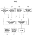
- the vehicle traveling control system for a vehicle in according with the present invention comprises a target vehicle speed setting section 1-1, a vehicle speed detecting section 1-2, an inter-vehicle distance detecting section 1-3, a target inter-vehicle distance setting section 1-4, a control content calculating section 1-5, a throttle operating section 1-6, an automatic brake operating section 1-7, a display content determining section 1-8, a display 1-9, and a traveling control section 1-10 which includes control content calculating section 1-5 and display content determining section 1-8.
- Target vehicle speed setting section 1-1 sets a target vehicle speed.
- the vehicle traveling control system executes a following control so that the vehicle speed does not becomes greater than the target vehicle speed.
- the vehicle traveling control system executes a cruise control so as to bring the vehicle speed closer to the target vehicle speed.
- Vehicle speed detecting section 1-2 detects the vehicle speed of the host vehicle. The vehicle speed is calculated from one of a revolution speed of an output shaft of a transmission and a revolution speed of one of wheels.
- Inter-vehicle distance detecting section 1-3 detects an inter-vehicle distance between the host vehicle and the preceding vehicle, and includes a laser radar, a millimeter wave radar, or a stereo camera.
- Target inter-vehicle distance setting section 1-4 sets a target inter-vehicle distance on the basis of a vehicle speed of the host vehicle.
- Control content calculating section 1-5 calculates a command brake hydraulic pressure and a command throttle opening so as to bring the detected inter-vehicle distance closed to the target inter-vehicle distance.
- Throttle operating section 1-6 controls a throttle so as to bring an actual throttle opening closer to the command throttle opening.
- Automatic brake operating section 1-7 controls brake hydraulic pressure so as to bring an actual brake hydraulic pressure closer to the command hydraulic pressure.
- Display content determining section 1-8 determines displayed content for informing control information to a driver. Display 1-9 displays the content determined by display content determining section 1-8.
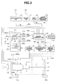
- Fig. 2 shows a total system of a vehicle traveling control system of a first embodiment according to the present invention.
- the host vehicle equipped with the vehicle traveling control system has a pair of front wheels 1FL and 1FR acting as driven (following) wheels and a pair of rear wheels 1RL and 1RR acting as driving wheels.
- Rear wheels 1RL and 1RR are driven by driving force which is generated by an internal combustion engine 2 and which is transmitted to rear wheels 1RL and 1RR through an automatic transmission 3, a propeller shaft 4, a final reduction gear 5, and an axle 6.
- a disc brake 7 is provided on each of front and rear wheels 1FL, 1FR, 1RL, and 1RR.
- a brake control unit 8 which corresponds to automatic brake operating section 1-7, controls brake hydraulic pressure applied to each disc brake 7.
- Brake control unit 8 is arranged to generate the brake hydraulic pressure according to a depression degree of brake pedal 16 and to generate the brake hydraulic pressure according to a target brake pressure PB* sent from traveling controller 30.
- An engine output control unit 9 is installed in engine 2 and controls the output of engine 2.
- Engine output control unit 9 functions as throttle operating section 1-6.
- Engine output control unit 9 controls the output of engine 2 by controlling the opening TH of a throttle valve of engine 2.
- Engine output control unit 9 may employ a method of controlling an idling speed of engine 2 by controlling the opening of an idle control valve, instead of the method of controlling the opening TH.
- Automatic transmission 3 is coupled to a transmission control unit 10 for controlling the transmission ratio of automatic transmission 3.
- Transmission control unit 10 executes an upshift control or a downshift control for changing the transmission ratio of automatic transmission 3 according to an up/down shift command TS outputted from traveling controller 30.
- Transmission control unit 10 selects a desired transmission ratio of forward/backward running, neutral position, and parking position of automatic transmission 3 according to a shift position signal Sp outputted from a shift lever 22.
- an inter-vehicle distance sensor 12 which function as inter-vehicle distance detecting section 1-3, is disposed at a front and lower portion of a vehicle body of the vehicle.
- Inter-vehicle distance sensor 12 is of a radar type which scans laser beams and receives a reflection beam reflected from a preceding vehicle. That is, this functions as a preceding vehicle recognizing means.
- a millimeter wave radar and a stereo camera may be employed individually or in parallel as inter-vehicle distance sensor 12 instead of the laser radar.
- the inter-vehicle distance may be obtained from image processing of image data obtained by a single-eyed camera with reference to base data obtained by a laser radar or a millimeter wave radar.
- Vehicle wheel speed sensors 13FL and 13FR are installed near front wheels 1FL and 1FR of the vehicle and function as vehicle speed detecting section 1-2.
- An accelerator switch 15 is disposed near an accelerator pedal 14 and detects depression of accelerator pedal 14.
- a brake switch 17 is disposed near a brake pedal 16 and detects depression of brake pedal 16.
- a brake hydraulic pressure sensor 18 detects the brake hydraulic pressure outputted from brake controller 8.
- a shift lever 22 indicates a shift position selected by a driver.
- the vehicle traveling control system further comprises a control panel in which there are provided with a main switch SW M and a set switch SW S through which following control is selected, a cancel switch SW C for commanding a cancellation of the following control, and a driving range detecting switch SW D for detecting that a select lever is set at a drive range (D range).
- Set switch SW S corresponds to target vehicle speed setting section 1-1 and target inter-vehicle distance setting section 1-4.
- Main switch SW M is connected to a battery B through an ignition switch SW IG and comprises a selector switch 20 of a momentary type and a relay circuit 21 of a self-hold type.
- Selector switch 20 is manually operated by a driver.
- selector switch 20 When selector switch 20 is set at OFF state, a first input terminal t i1 receiving a switch signal SI G is electrically shut off from an output terminal t o .
- selector switch 20 is set at a neutral state, a second input terminal t i2 receiving electric power from relay circuit 21 is electrically connected with output terminal t o .
- selector switch 20 is set at ON state, both of first and second input terminals t i1 and t i2 are electrically connected with output terminal t o .
- Relay circuit 21 comprises a normal-open contact s1 and a relay coil RL for driving normal-open contact s1.
- One terminal of normal-open contact s1 is connected with ignition switch SW IG , and the other terminal of normal-open contact s1 is connected with traveling controller 30 directly and through set switch SW S . Further, the other terminal is connected with second input terminal t i2 of selector switch 20.
- One terminal of relay coil RL is connected with output terminal t o of selector switch 20, and the other terminal of relay coil RL is grounded.
- Traveling controller 30 receives information signals from inter-vehicle distance sensor 12, wheel speed sensors 13FL and 13FR, accelerator switch 15, brake switch 17, and brake pressure sensor 18, respectively. Further, traveling controller 30 receives a shift position indicative signal Sp from shift lever and switch signals S M , S SET , S CAN , and S DR from main switch SW M , set switch SW S , cancel switch SW C , and drive range detecting switch SW D , respectively.
- Traveling controller 30 outputs a display command to display 1-9 integrally assembled with a meter panel 2-1 provided in a passenger compartment, in order to inform necessary information to the driver by displaying the information on display 1-9.
- Meter panel 2-1 comprises a speedometer 2-2 and display 1-9 installed in speedometer 2-2, as shown in Fig. 3A.
- Display 1-9 is disposed under a center shaft of a pointer of speedometer 2-2, and comprises a cruise control execution indicating lamp 1-91, a system abnormality warning lamp 1-92, a set vehicle speed display section 1-93, a set inter-vehicle distance display section 1-94, and a preceding vehicle display section 1-95 for displaying the existence of a preceding vehicle, as shown in Fig. 3B.
- Display 1-9 comprises a speed range display section 1-96 which is disposed along a speed scale of analog-type speedometer 2-2 in a belt shape as shown in Fig. 3C.
- Speed range display section 1-96 is constituted by a luminous sheet or a plurality of LED's arranged along a scale of speedometer 2-2 so as to be able to display a speed range.
- a part or all of the speed range can be set at ON state and OFF state so that an area (vehicle speed range) set at ON state is varied according to whether a set condition ON state or a control condition ON state is selected.
- Fig. 4 shows variations of mode transitions executed by the control content calculating section of traveling controller 30.
- a control standby mode 3-1 is selected when main switch SW M is turned on from an OFF state.
- traveling controller 30 calculates a throttle opening command and a brake command so as to bring an actual inter-vehicle distance L closer to a target inter-vehicle distance L* set (based on the vehicle condition including the vehicle speed) by a target inter-vehicle distance setting section as far as a vehicle speed of a host vehicle does not becomes over the target vehicle speed which is set by a driver through a target vehicle speed setting section.
- traveling controller 30 calculates the throttle opening command and the brake command so as to bring the actual vehicle speed closer to the set vehicle speed.
- traveling controller 30 When control rest mode 3-3 is selected and when traveling controller 30 detects that the driver executes an acceleration operation during the following control (following mode), traveling controller 30 stops the control in the following mode so that the acceleration operation by the driver is executed by priority.
- Transition condition I is established when the host vehicle travels at a vehicle speed in D range within a predetermined speed range and when set switch SW S is turned on by the pushing operation of the driver.
- transition condition I is satisfied, the control mode is transited from control standby mode 3-1 to following mode (control execution mode) 3-2.
- Transition condition II is established when the host vehicle travels under following mode 3-2 and when accelerator pedal 14 is depressed by the driver. When the transition condition II is satisfied, the control mode is transited from following mode 3-2 to control rest mode 3-3.
- Transition condition III is established when the host vehicle is accelerated by the depression of accelerator pedal 14 under control rest mode 3-3. when accelerator pedal 14 is released. When transition condition III is satisfied, the control mode is transited from control rest mode 3-3 to following mode 3-2.
- Transition condition IV is established when the host vehicle travels under following mode 3-2 and when one of the turning on of cancel switch SW C , the shifting operation, and the increase of the depression degree of brake pedal is executed.
- the control mode is transited from following mode 3-2 to control rest mode 3-1.
- Transition condition V is established when the host vehicle is accelerated by the depression of the accelerator pedal under control rest mode 3-3 and when one of the turning on of cancel switch SW C , the shifting operation, and the increase of the vehicle speed over a predetermined value is executed.
- the control mode is transited from control rest mode 3-3 to control standby mode 3-1.
- Fig. 5 shows a flowchart of a following control process executed by control contend calculating section of traveling controller 30 as a main program.
- traveling controller 30 determines whether or not the control mode is a control standby mode. When the determination at step S401 is affirmative, the routine proceeds to step S402. When the determination at step S401 is negative, the routine proceeds to step S403.
- controller 30 executes a standby-mode transition selecting routine.
- controller 30 determines whether or not the following mode is selected. When the determination at step S403 is affirmative, the routine proceeds to step S404. When the determination at step S403 is negative, the routine proceeds to step S405.
- controller 30 executes a following-mode transition selecting routine.
- controller 30 executes a rest-mode transition selecting routine.
- controller 30 determines whether or not the control rest mode is selected. When the determination at step S406 is affirmative, the routine proceeds to step S407. When the determination at step S406 is negative, the routine proceeds to step S408.
- controller 30 executes a routine of the control standby mode, shown in Fig. 6A.
- controller 30 determines whether or not the following mode is selected. When the determination at step S408 is affirmative, the routine proceeds to step S409. When the determination at step S408 is negative, the routine proceeds to step S410.
- controller 30 executes a routine of the following mode (the control execution mode), shown in Fig. 6B.
- controller executes a routine of the control rest mode, shown in Fig. 6C.
- traveling controller 30 measures the actual vehicle speed.
- controller 30 reads the shift position.
- controller 30 detects the braking operation executed by the driver.
- controller 30 reads the state of set switch SW S by determining whether set switch SW S is turned on by the driver.
- traveling controller 30 reads the state of cancel switch SW C by determining whether the driver turns on cancel switch SW C .
- controller 30 measures the actual inter-vehicle distance.
- controller 30 measures the actual vehicle speed.
- controller 30 reads the shift position.
- controller 30 detects the braking operation executed by the driver.
- controller 30 reads the accelerating operation executed by the driver.
- controller 30 sets a command brake pressure.
- controller 30 sets a command throttle opening.
- traveling controller 30 measures the actual vehicle speed.
- controller 30 reads the shift position.
- controller 30 detects the accelerating operation executed by the driver.
- controller 30 reads the state of cancel switch SW C by determining whether the driver turns on cancel switch SW C .
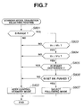
- Fig. 7 shows a flowchart for determining a transited mode from the control standby mode.
- traveling controller 30 determines whether D range is selected or not. When the determination at step S801 is affirmative, the routine proceeds to step S803. When the determination at step S801 is negative, the routine proceeds to step S802.
- controller 30 terminates the present routine while maintaining the control standby mode.
- controller 30 determines whether vehicle speed V H is greater than or equal to a first threshold V T1 such as 48km/h. When the determination at step S803 is affirmative, the routine proceeds to step S804. When the determination at step S803 is negative, the routine proceeds to step S802.
- controller 30 determines whether vehicle speed V H is greater than or equal to a second threshold V T2 such as 11km/h. When the determination at step S804 is affirmative, the routine proceeds to step S805. When the determination at step S804 is negative, the routine proceeds to step S802.
- controller 30 determines whether or not the brake pedal is depressed by the driver. When the determination at step S805 is negative, the routine proceeds to step S806. When the determination at step S805 is affirmative, the routine proceeds to step S802.
- controller 30 determines whether or not the set switch SW S is turned on by the driver. When the determination at step S806 is affirmative, the routine proceeds to step S807. When the determination at step S806 is negative, the routine proceeds to step S802.
- controller 30 changes the control mode from the control standby mode to the following mode. Then, controller 30 terminates the present routine of Fig. 6.
- Fig. 8 shows a flowchart for determining a transited mode to be transited from the following mode.
- traveling controller 30 determines whether cancel switch SW C is pushed or not. When the determination at step S901 is affirmative, the routine proceeds to step S902. When the determination at step S901 is negative, the routine proceeds to step S903.
- controller 30 changes the control mode from the following mode to the control standby mode. Then, controller 30 terminates the present routine of Fig. 8.
- controller 30 determines whether or not the shift position is changed. When the determination at step S903 is affirmative, the routine proceeds to step S907. When the determination at step S903 is negative, the routine proceeds to step S904.
- controller 30 determines whether or not the brake is depressed by the driver. When the determination at step S904 is affirmative, the routine proceeds to step S907. When the determination at step S904 is negative, the routine proceeds to step S905.
- controller 30 determines whether or not the vehicle speed V H is smaller than or equal to a predetermined value V T3 such as 38km/h. When the determination at step S905 is affirmative, the routine proceeds to step S907. When the determination at step S905 is negative, the routine proceeds to step S906.
- controller 30 determines whether or not the driver is accelerating the host vehicle by increasing the depressing degree of the accelerator pedal. When the determination at step S906 is affirmative, the routine proceeds to step S908. When the determination at step S906 is negative, the routine proceeds to step S909.
- controller 30 alarms the driver that the control mode is changed from the following mode to the control standby mode due to the condition change determined at one of steps S903, S904 and S905. Then, the routine proceeds to step S902.
- controller 30 changes the control mode from the following mode to the control rest mode. Then, controller 30 terminates the present routine of Fig. 8.
- controller 30 maintains the following mode. Then, controller 30 terminates the present routine of Fig. 8.
- Fig. 9 shows a flowchart for determining a transited mode to be transited from the control rest mode.
- traveling controller 30 determines whether or not the D range is selected. When the determination at step S1001 is affirmative, the routine proceeds to step S1002. When the determination at step S1001 is negative, the routine proceeds to step S1007.
- controller 30 determines whether or not the driver is depressing accelerator pedal 14. When the determination at step S1002 is negative, the routine proceeds to step S1003. When the determination at step 1002 is affirmative, the routine proceeds to step S1004.
- controller 30 changes the control mode from the control rest mode to the following mode. Then, controller 30 terminates the present routine of Fig. 9.
- controller 30 determines whether or not the vehicle speed is smaller than a predetermined value V T4 , e.g. 120km/h. When the determination at step S1004 is affirmative, the routine proceeds to step S1005. When the determination at step S1004 is negative, the routine proceeds to step S1007.
- V T4 a predetermined value
- controller 30 determines whether or not the cancel switch is pushed. When the determination at step S1005 is affirmative, the routine proceeds to step S1008. When the determination at step S1005 is negative, the routine proceeds to step S1006.
- controller 30 maintains the control rest mode without changing to others. Then, control 30 terminates the present routine of Fig. 9.
- controller 30 alarms the driver that the control mode is changed from the control rest mode to the control standby mode. Then, the routine proceeds to step S1008.
- controller 30 changes the control mode from the control rest mode to the control standby mode. Then, controller 30 terminates the present routine of Fig. 9.
- Display content determining section 1-8 of traveling controller 30 determines the displayed content for informing the control condition to the driver concurrent with the execution of the processes shown in Figs. 5 through 9. Such display content is displayed on display 1-9 assembled in speedometer 2-2 as shown in Fig. 3A.
- Fig. 10 shows a flowchart of a steady-state information determining process for determined a display content to be displayed on a cruise-control execution indicating lamp 1-91, a system abnormality warning lamp 1-92, a set-speed display section 1-93, a set inter-vehicle distance display section 1-94, a preceding-vehicle display section 1-95 shown in Fig. 3B.
- traveling controller 30 determines whether main switch SW M is pushed (turned on) or not. When the determination at step S1101 is negative, the routine proceeds to step S1102. When the determination at step S1101 is affirmative, the routine proceeds to step S1103.
- controller 30 turns off all of abnormality warning lamp 1-92, a set speed display section 1-93, a set inter-vehicle distance display section 1-94, a preceding vehicle display section 1-95. Then, controller 30 terminates the present routine of Fig. 10.
- controller 30 turns on cruise-control execution indicating lamp 1-91 and inter-vehicle distance display section 1-94.
- controller 30 determines whether the set inter-vehicle distance is changed or not. When the determination at step S1104 is affirmative, the routine proceeds to step S1105. When the determination at step S1104 is negative, the routine proceeds to step S1106.
- controller 30 changes the displayed content of the set inter-vehicle distance display section 1-94 to the changed set inter-vehicle distance.
- controller 30 determines whether set switch SW S is pushed or not. When the determination at step S1106 is affirmative, the routine proceeds to steps S1107. When the determination at step S1106 is negative, the routine proceeds to step S1113.
- controller 30 displays the vehicle speed at the timing of pushing main switch SW S on set speed display section 1-93 as a set speed.
- controller 30 determines whether set speed is changed or not. When the determination at step S1108 is affirmative, the routine proceeds to step S1109. When the determination at step S1108 is negative, the routine proceeds to steps S1110.
- controller 30 rewrites the set speed displayed on set speed display section 1-93 to the changed set speed.
- controller 30 determines whether or not a preceding vehicle is recognized. When the determination at step S1110 is affirmative, the routine proceeds to step S1111. When the determination at step S1110 is negative, the routine proceeds to step S1112.
- controller 30 turns on preceding vehicle display section 1-95. Then, controller 30 terminates the present routine of Fig. 10.
- controller 30 turns off preceding vehicle display section 1-95. Then, controller 30 terminates the present routine of Fig. 10.
- controller 30 determines whether cancel switch SW C is pushed or not.
- the routine proceeds to step S1114.
- the routine returns to step S1104.
- controller 30 turns off all of system abnormality warning lamp 1-92, set speed display section 1-93 and preceding vehicle display section 1-95 except for cruise-control execution indicating lamp 1-91 and set inter-vehicle distance display section 1-94. Then, controller 30 terminates the present routine of Fig. 10.
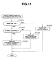
- Fig. 11 shows a flowchart of a speed range display determining process for determining a speed range to be displayed on vehicle speed range display section 1-96.
- traveling controller 30 determines whether main switch SW M is pushed or not. When the determination at step S1201 is negative, the routine proceeds to step S1202. When the determination at step S1201 is affirmative, the routine proceeds to step S1203.
- controller 30 turns off the speed-range display 1-96. Then, controller 30 terminates the present routine of Fig. 11.
- controller 30 determines whether the control is set or not. When the determination at step S1203 is negative, the routine proceeds to step S1204. When the determination at step S1203 is affirmative, the routine proceeds to step S1205.
- controller 30 turns on a set-condition speed range such as a range from 48km/h to 110km/h, on speed range display section 1-96. Then, controller 30 terminates the present routine of Fig. 11.
- the set-condition speed range represents a speed range within which it is possible to execute a setting operation of the traveling control. This definition of the set-condition speed range is employed in the whole embodiments of the present invention.
- controller 30 turns on a control-condition speed range such as a range from 38km/h to 120km/h, on speed range display section 1-96. Then, controller 30 terminates the present routine of Fig. 11.
- the "control-condition speed range” represents a speed range within which it is possible to continue the traveling control. This definition of the control-condition speed range is employed in the whole embodiments of the present invention.
- step S1201 When main switch SM M is not pushed (turned off), the routine of the flowchart of Fig. 11 proceeds from step S1201 to step S1202 wherein speed range display section 1-96 of speedometer 2-2 is turned off. Therefore, the speed range is not displayed.
- controller 30 commands speed range display section 1-96 to display the set-condition speed range wherein it is possible to execute the set operation enabling, as shown Fig. 12B.
- set-condition speed range is, for example, a range from 48 to 110km/h.
- the driver When the driver intends to execute the traveling control during the vehicle traveling condition, the driver first looks at speedometer 2-2 to recognize that the present vehicle speed indicated by a pointer of speedometer 2-2 is within the set-condition speed range displayed by speed range display section 1-96. Then, the driver pushes set switch SW S after the recognition of the vehicle speed with in the set-condition speed range. By this turning on of set switch SW S , controller 30 executes the set operation during a traveling condition where the set condition is established. Therefore, the control mode is changed from the control standby mode to the following mode, and the traveling control is started.
- controller 30 commands speed range display section 1-96 of speedometer 2-2 to display the control-condition speed range wherein it is possible to continue the traveling control, as shown Fig. 12C.
- control-condition speed range is, for example, a range from 38 to 120km/h.
- the driver can recognize that the present vehicle speed indicated by the pointer of speedometer 2-2 is within the control-condition speed range display by speed range display section 1-96, by looking at speedometer 2-2. That is, the driver can recognize whether it is now possible to continue the traveling control.
- a traveling controller 30 which transits the control mode from the control standby mode to the following mode, when set switch SW S is pushed during the vehicle traveling condition where the set condition is satisfied.
- the speed range display section 1-96 is provided along speedometer 2-2.
- Traveling controller 30 comprises a display content determining section 1-8 which outputs a display command for displaying the set-condition speed range during the non-set condition and a display command for displaying the control-condition speed range to the speed range display section 1-96. Therefore, it is not necessary that the driver remembers the set-condition speed range in that it is possible to execute the set operation for the traveling control and the control-condition speed range in that it is possible to continue the traveling control. Further, it becomes possible to easily compare the present vehicle speed with the set-condition speed range and the control-condition speed range by having a glance at speedometer 2-2. This arrangement improves the utility of the traveling control.
- a second embodiment of the vehicle traveling control system with the state display apparatus there is shown a second embodiment of the vehicle traveling control system with the state display apparatus according to the present invention.
- the speed range display determining process is executed by flowcharts of Figs. 13, 14 and 15 instead of the control of Fig. 11 executed in the first embodiment.
- the structure and functions of the second embodiment are generally the same as those of the first embodiment shown in Figs. 1 to 10 and 12. Therefore, the explanation thereof is omitted herein.
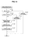
- Fig. 13 is a main flowchart showing the speed range display content determining process.
- traveling controller 30 determines whether main switch SW M is turned on or not. When the determination at step S1401 is negative, the routine proceeds to step S1402. When the determination at step S1401 is affirmative, the routine proceeds to step S1403.
- controller 30 turns off speed range display section 1-96. Then, controller 30 terminates the present routine of Fig. 13.
- controller 30 determines whether the control is set or not. When the determination at step S1403 is negative, the routine proceeds to step S1404. When the determination at step S1403 is affirmative, the routine proceeds to step S1405.
- controller 30 turns on the set-condition speed range, such as a range from 38 to 110km/h, on speed range display section 1-96.
- controller 30 turns on the speed range corresponding to the variable range of the set vehicle speed, such as a range from 40 to 110km/h on speed range display section 1-96.
- controller 30 executes the rewriting of an upper limit of speed range display by executing a routine shown in Fig. 14.
- controller 30 executes the rewriting of a lower limit of speed range display by executing a routine shown in Fig. 15. Then, controller 30 terminates the present routine of Fig. 13.
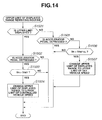
- Fig. 14 is a flowchart showing a rewiring routine of the upper limit of the speed range display.
- traveling controller 30 determines whether or not the upper limit of the set speed such as 110km/h is displayed on speed range display section 1-96. When the determination at step S1501 is affirmative, the routine proceeds to step S1502. When the determination at step S1501 is negative, the routine proceeds to step S1505.
- controller 30 determines whether or not the driver is increasing the depression degree of the accelerator pedal. When the determination at step S1502 is affirmative, the routine proceeds to step S1503. When the determination at step S1502 is negative, the routine proceeds to an end block to terminate the present routine of Fig. 14 without changing the upper limit of the displayed speed range.
- controller 30 determines whether vehicle speed V H is greater than a set speed V SET or not.
- V H > V SET the routine proceeds to steps S1504.
- V H ⁇ V SET the routine proceeds to the end block.
- controller 30 rewrites the upper limit of the display range to the upper vehicle speed (high cut vehicle speed) of the control.
- the upper limit of the display range is changed from 110km/h to 120km/h.
- the displayed upper limit is the upper limit of the controlled vehicle speed such as 120km/h since the displayed upper limit displayed during the control is one of the upper limit of the set vehicle speed and the upper limit of the controlled vehicle speed. Accordingly, when the displayed upper limit is the upper limit of the controlled vehicle speed, the routine proceeds to step S1505.
- controller 30 determines whether the driver is increasing the depression degree of the accelerator pedal. When the determination at step S1505 is affirmative, the routine proceeds to the end block. When the determination at step S1505 is negative, the routine proceeds to step S1506.
- controller 30 determines whether vehicle speed V H is smaller than the upper limit V SETUL (such as 110km/h) of the set vehicle speed or not. When the determination at step S1506 is affirmative, the routine proceeds to steps S1507. When the determination at step S1506 is negative, the routine proceeds to the end block to terminate the present routine without rewiring the upper limit.
- V SETUL such as 110km/h
- controller 30 rewrites the upper limit of the display range to the upper limit of the set vehicle speed (such as 110km/h).
- Fig. 15 is a flowchart showing a rewriting routine of the lower limit of the speed range display.
- traveling controller 30 determines whether or not the lower limit of the set speed such as 50km/h is displayed on the speed range display section 1-96. When the determination at step S1601 is affirmative, the routine proceeds to step S1602. When the determination at step S1601 is negative, the routine proceeds to step S1605.
- controller 30 determines whether or not the inter-vehicle distance controller is being executed. When the determination at step S1602 is affirmative, the routine proceeds to step S1603. When the determination at step S1602 is negative, the routine proceeds to an end block to terminate the present routine of Fig. 15 without changing the lower limit of the display range.
- controller 30 determines whether or not vehicle speed V H is smaller than a predetermined value V T5 such as 50km/h. When the determination at step S1603 is affirmative, the routine proceeds to steps S1604. When the determination at step S1603 is negative, the routine proceeds to the end block.
- controller 30 rewrites the lower limit of the display range to the lower-limit vehicle speed (low-cut vehicle speed) of the control.
- the lower limit of the display range is changed from 50km/h to 38km/h.
- the displayed lower limit is the lower limit of the host vehicle speed such as 38km/h since the displayed lower limit displayed during the control is one of the lower limit (such as 50km/h) of the set vehicle speed and the lower limit (such as 38km/h) of the controlled vehicle speed. Accordingly, when the displayed lower limit is the lower limit of the controlled vehicle speed, the routine proceeds to step S1605.
- controller 30 determines whether or not the inter-vehicle distance controller is being executed. When the determination at step S1605 is affirmative, the routine proceeds to step S1606. When the determination at step S1605 is negative, the routine proceeds to step S1607.
- controller 30 determines whether or not vehicle speed V H is smaller than a predetermined value V T5 such as 50km/h. When the determination at step S1606 is affirmative, the routine proceeds to the end block. When the determination at step S1606 is negative, the routine proceeds to steps S1607.
- controller 30 rewrites the lower limit of the display range to the lower limit of the set vehicle speed (such as 50km/h).
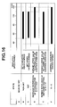
- step S1401 the routine of the flowchart of Fig. 13 proceeds from step S1401 to step S1402 wherein speed range display section 1-96 of speedometer 2-2 is turned off as shown by (A) in Fig. 16. Therefore, the speed range is not displayed.
- traveling controller 30 commands speed range display section 1-96 to display the set-condition speed range where it is possible to execute the setting operation, as shown by (B) of Fig. 16.
- set-condition speed range is, for example, a range from 48 to 110km/h.
- the driver when the driver intends to execute the traveling control during the vehicle traveling condition, the driver first looks at speedometer 2-2 to recognize that the present vehicle speed indicated by a pointer of speedometer 2-2 is within the set-condition speed range displayed by speed range display section 1-96. Then, the driver pushes set switch SW S after the recognition of the vehicle speed within the set-condition speed range. By this turning-on of set switch SW S , controller 30 executes the set operation during a traveling condition where the set condition is established. Therefore, the control mode is changed from the control standby mode to the following mode.
- traveling controller 30 follows the preceding vehicle by executing an inter-vehicle distance control for bringing the measured inter-vehicle distance closer to the target inter-vehicle distance and by controlling the actual vehicle speed so as to be smaller than the target vehicle speed.
- traveling controller 30 executes the constant speed control (cruise control) for bring the measured vehicle speed closer to the target vehicle speed.
- traveling controller 30 commands speed range display section 1-96 of speedometer 2-2 to display the speed range corresponding to a variable range of the set vehicle speed as shown by (C) of Fig. 16.
- speed range corresponding to the variable range of the set vehicle speed is, for example, a range from 50 to 110km/h.
- traveling controller 30 outputs a command for displaying the extended control-condition speed range which is extended to the maximum value of the control condition, and therefore speed range display section 1-96 of speedometer 2-2 displays the extend control-condition speed range whose upper limit is extended to the upper limit of the control condition.
- the speed range is set at a range from 50 to 120km/h.
- the routine of Fig. 14 proceeds in the order of S1501 ⁇ step S1505 ⁇ step S1506 ⁇ step S1507. Therefore, the speed range is returned to an original state which is the variable range of the set vehicle speed such as a range 50 to 110km/h.
- controller 30 outputs a command for displaying the speed range which is extended to the minimum value of the control condition, and therefore speed range display section 1-96 of speedometer 2-2 displays the extend speed range whose lower limit is extended to the lower limit of the control condition.
- the speed range is set at a range from 38 to 110km/h.
- step S1601 the routine of Fig. 15 proceeds in the order of step S1601 ⁇ step S1605 (step S1606) ⁇ step S1607. Therefore, the speed range is returned to an original state which corresponds to the variable range of the set vehicle speed, such as a range 50 to 110km/h).
- the vehicle speed range of the control condition is, for example, a range from 38 to 120km/h as shown by (F) of Fig. 16.
- the set vehicle speed is a maximum vehicle speed during the control. Only when the driver increases the depression degree of the accelerator pedal, the vehicle speed becomes greater than the set speed (reaches 120km/h). Accordingly, it is possible to limit the necessary situation for displaying the control high-cut vehicle speed (control upper limit) to the situation that the driver is increasing the depression degree of the accelerator pedal. Further, only when the inter-vehicle distance control is executed, the vehicle speed becomes smaller than the set speed. Accordingly, it is possible to limit the necessary situation for displaying the control low-cut vehicle speed (control upper limit) to the situation that the inter-vehicle distance control is executed.
- the variable range of the set speed is basically set at a range such as 50 to 110km/h, and only when the traveling situation (the increasing depression of accelerator pedal and the vehicle speed condition), the upper limit of the set vehicle speed is extended to the upper limit of the control condition and is displayed. Further, only when the traveling situation (the inter-vehicle distance control and the vehicle speed condition) is satisfied, the lower limit of the set vehicle speed is extended to the lower limit of the control condition and is displayed.
- the control mode is transited from the control standby mode to the following mode when set switch SW S is pushed during the set-condition satisfying traveling state.
- the speed range display section 1-96 is provided along speedometer 2-2.
- Traveling controller 30 comprises a display content determining section 1-8 which outputs a display command for displaying the set-condition speed range during the non set condition and a display command for displaying the speed range corresponding to a variable range of the set vehicle speed, for displaying the upper extended speed range whose upper limit is extended to the maximum value of the control condition only when the driver increases the depression degree of the accelerator pedal, and a display command for displaying the lower extended speed range whose lower limit is extended to the minimum value of the control condition. Therefore, the driver can further easily recognize the information relating to the traveling control system.
- the second embodiment is arranged such that the display of the variable range of the set vehicle speed is extended to the maximum value of the control condition and to the lower minimum value of the control condition without switching the variable range of the set vehicle speed and the speed range of the control condition, it possible to eliminate unnecessary switching of the speed range, and therefore the driver can further easily recognize the speed range.
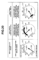
- FIG. 17 there is shown a third embodiment of the vehicle traveling control system with the state display apparatus according to the present invention.
- the third embodiment is specifically arranged such that when the speed range is displayed on the vehicle speed range display section 1-96, the present set vehicle speed and the settable vehicle speed which the driver can set by every 5km/h, are displayed (indicated by every 5km/h) as shown in Fig. 17.
- the present set vehicle speed is displayed and the settable vehicle speed set by the driver is pointed. Therefore, the driver easily and clearly recognizes the set condition of the vehicle speed range.
- traveling controller 30 comprises an adaptive cruise control system (ACC system) for controlling an inter-vehicle distance at high-speed cruising condition and an inching control system for controlling running of the vehicle under an extremely low speed condition including the traffic congestion condition.
- ACC system adaptive cruise control system
- inching control system for controlling running of the vehicle under an extremely low speed condition including the traffic congestion condition.
- a high-speed range display section 1-96H for displaying the vehicle speed range during the high speed traveling control and a low-speed range display section 1-96L for displaying the vehicle speed range during the low speed travel control are displayed along the vehicle-speed scale of speedometer 2-2. Further, display content determining section 1-8 of traveling controller 30 outputs the display command to high-speed range display section 1-96H and/or low-speed range display section 1-96L according to whether the set condition or not.
- the fourth embodiment is arranged such that the mode transition content shown in Fig. 4 of the first embodiment is changed to the mode transition content adapted to the two speed ranges of the high-speed range and the low-speed range as shown in Fig. 18. Further, the speed range display determining process shown in Fig. 19 is employed instead of the process of the first embodiment shown in Fig. 11, so that the example thereof is shown in Fig. 20.
- Fig. 18 shows a condition transition among the control modes in the control content calculating section 1-5 of traveling controller 30.
- 19-1 denotes the control standby mode as is similar to Fig. 4 and is introduced when main switch SW M is turned on from an off state.
- 19-2 denotes a condition that the high-speed range traveling control (automatic inter-vehicle distance control system) at a high-speed range, such as 50km/h to 110km/h, is being executed.
- the following mode 3-2 and the control rest mode 3-3 shown in Fig. 4 exist.
- 19-3 denotes a condition that the low-speed range traveling control (traffic-congestion following control system) at a low speed range, such as 5km/h to 30km/h, is being executed.
- following mode 3-2 and control rest mode 3-3 shown in Fig. 4 exist.
- the transition from the control standby mode 19-1 to the high speed range traveling control 19-2 is executed when the host vehicle travels at a predetermined speed at D range (for example, in a range 50km/h to 110km/h) and when set switch SW S is pushed.
- the transition from high-speed range traveling control 19-2 to control standby mode 19-1 is executed when cancel switch SW C is pushed or when the predetermined cancel condition satisfied.
- the transition from control standby mode 19-1 to low-speed range traveling control 19-3 is executed when the host vehicle travels at another predetermined speed at D range (for example, in a range 5km/h to 30km/h) and when set switch SW S is pushed during the traveling condition.
- the transition from low-speed range traveling control 19-3 to control standby mode 19-1 is executed when cancel switch SW C is pushed or when a predetermined cancel condition is satisfied.
- Fig. 19 shows a flowchart of the vehicle speed range display content determining process.
- traveling controller 30 determines whether main switch SW M has been pushed or not. When the determination at step S2001 is affirmative, the routine proceeds to step S2003. When the determination at step S2001 is negative, the routine proceeds to step S2002 wherein controller 30 turns off high-speed range display section 1-96H and low-speed range display section 1-96L. Then the present routine of Fig. 19 is terminated.
- controller 30 displays the speed range corresponding the set condition on the high-speed range display section 1-96H, such as 50-110km/h, and simultaneously displays the speed range corresponding to the set condition on the low-speed range display section 1-96L, such as 5-30km/h.
- controller 30 determines whether the control (automatic inter-vehicle distance control) at the high-speed range is set or not. When the determination at step S2004 is affirmative, the routine proceeds to step S2005. When the determination at step S2004 is negative, the routine proceeds to step S2006.
- controller 30 changes the display appearance, for example in color or brightness, of the displayed content of the speed range corresponding to the high-speed range control condition, such as 50-120km/h.
- controller 30 determines whether the control at the low-speed range is set or not. When the determination at step S2006 is affirmative, the routine proceeds to step S2007. When the determination at step S2006 is negative, the routine proceeds to the end block to terminate the present routine.
- controller 30 changes the display appearance, for example, in color or brightness of the displayed content of the low-speed range control-condition speed range, such as 5-30km/h.
- step S2002 the routine of Fig. 19 proceeds from step S2001 to step S2002, and at step S2002 the speed range display section 1-96 (high speed range display section 1-96H and low speed range display section 1-96L) of speedometer 2-2 is turned off to stop the display of the speed range.
- the routine of Fig. 19 proceeds in the order of step S2001 ⁇ step S2003 ⁇ step S2004 ⁇ step S2006 ⁇ end block.
- the driver When the driver intends to execute the traveling control during the vehicle traveling condition, the driver first checks whether the present vehicle speed pointed by the pointer of the speedometer 2-2 is in the set-condition speed range displayed on the high-speed range display section 1-96H or the low-speed range display section 1-96L. When the present vehicle speed is in the displayed speed range, the driver then pushes set switch SW S . With this pushing operation, the set operation during the traveling condition in that the set condition is established is executed. Therefore, when the vehicle travels at low speed, the control mode is transited from the control standby mode to the low-speed range traveling control by which the traffic-congestion following control system is executed. When the vehicle travels at high speed, the control mode is transited from the control standby mode to the high-speed range traveling control by which the inter-vehicle distance control is executed.
- the high-speed range control-condition speed range is displayed on the high-speed range display section 1-96H of speedometer 2-2 as shown in Fig. 20.
- the appearance of the displayed speed range is changed from that of the set-condition display executed during the non-control state. Particularly, the appearance is changed in color or brightness.
- the low-speed range control-condition speed range is displayed on the low-speed range display section 1-96L of speedometer 2-2 as shown in Fig. 20.
- the appearance of the displayed speed range is changed from that of the set-condition display executed during the non-control state. Particularly, the appearance is changed in color or brightness.
- the vehicle traveling control system of the fourth embodiment comprises traveling controller 30 which executes a mode transition from the control standby mode to the high-speed range traveling control mode or the low-speed range traveling control mode when set switch SW S is pushed during a traveling condition in which the set condition is established.
- the state display apparatus of the fourth embodiment comprises a high-speed range display section 1-96H for displaying a speed range of the high speed range traveling control along the scale of the speedometer 2-2 and a low-speed range display section 1-96L for displaying a speed range of the low speed range traveling control along the scale of the speedometer 2-2.
- the display content determining section 1-8 is arranged to display the speed range while the appearance of the speed range is changed such as in color or brightness or design according to whether it is now set at a set condition or non-control condition, even if a plurality of control systems which operated in the respective speed ranges are employed in the vehicle. Therefore, the driver can utilize these systems without remembering the respective speed ranges of the respective controls. Further, the driver can easily recognize which one of the controls is operating.
- a fifth embodiment of the vehicle traveling control system with the state display apparatus there is shown a fifth embodiment of the vehicle traveling control system with the state display apparatus according to the present invention.
- the high-speed range display and the low-speed range display are specially arranged such that the driver can easily recognize which one of the two controls is operating even when the set-condition speed range is overlapped with the control-condition speed range.
- the high speed range display section 1-96H and the low speed range display section 1-96L are offset in the diametrical direction so that they have the overlapped portions respectively, such as 25-50km/h.
- the display content determining section 1-8 of the traveling controller 30 may be arranged such that when the speed range of the set condition is overlapped with the speed range of the control condition, only the speed range in the controlled condition of one of the set condition and the control condition is displayed.
- the speed range corresponding to the set condition of the low speed range traveling control is not displayed (turned off).
- the control-condition speed range of the high speed range traveling control is not displayed (turned off), as shown by lower side figures in Fig. 21.
- FIG. 22 there is shown a sixth embodiment of the vehicle traveling control system with the state display apparatus according to the present invention.
- the sixth embodiment is arranged such that in the fourth embodiment the appearance such as color, design, or brightness of the display is changed according to whether the present operating system is the inter-vehicle distance control active in the high-speed range or the traffic-congestion following control system active in the low-speed range.
- the driver can easily recognize the system which is now operating.
- the display content determining section 1-8 of traveling controller 30 of the sixth embodiment is arranged such that the displaying method (appearance) is changed according to the operating system of the inter-vehicle distance control system (ACC system) operated in the high speed-range and the traffic-congestion following control system operated in the low-speed range, as shown in Fig. 21.
- ACC system inter-vehicle distance control system
- Fig. 21 the operating system of the inter-vehicle distance control system
- the appearance of the displayed content is changed.
- the relativity between the speed range display content and the displayed steady state information is further easily recognized.
- a seventh embodiment of the vehicle traveling control system with the state display apparatus is specifically arranged such that the control mode of traveling controller 30 comprises a not-ready state (control standby mode) during the non-control state, a set ready state (control rest mode) during the non-control state, and a control state (traveling control mode). Further, display content determining section 1-8 is arranged such that the appearance of the displayed speed range is changed in color, design or brightness according to the control state selected from the not-ready state during the non-control state, the set ready state during the non-control state and the control state.
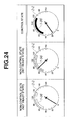
- Fig. 23 shows a flowchart of the vehicle speed range display content determining process of the seventh embodiment.
- traveling controller 30 determines whether main switch SW M is pushed or not. When the determination at step S2401 is negative, the routine proceeds to step S2402. When the determination at step S2401 is affirmative, the routine proceeds to step S2403.
- controller 30 turns off the vehicle speed range display section 1-96. Then, the routine proceeds to an end block to terminate the present routine.
- controller 30 determines whether the set condition is satisfied or not.
- the set condition includes a vehicle speed condition, a shift position set at D range, a brake condition that brake is not depressed, a not-low friction road surface that ABS, TCS, or VDC is inoperative, no radar trouble that there is no interference of radio wave and no dirt of a radar apparatus.
- the routine proceeds to step S2405.
- the routine proceeds to step S2404.
- controller 30 displays the set-condition speed range whose appearance characteristically indicates the not ready state by characteristically changing color, brightness, or design. Then, the routine proceeds to the end block to terminate the present routine.
- controller 30 determines whether the control is set or not.
- the routine proceeds to step S2407.
- the determination at step S2405 is negative, that is, when it is in non-set state
- the routine proceeds to step S2407.
- controller 30 displays the set-condition speed range by changing the appearance of the displayed speed range in color, brightness or design so as to indicate the ready state. Then, the routine proceeds to the end block.
- controller 30 displays the control-condition speed range by differentiating its appearance from those of the not-ready state and the ready state in color, brightness, or design. Then, the routine proceeds to the end block.
- step S2402 controller 30 turns off the speed range display section 1-96 of speedometer 2-2, and therefore the speed range is not displayed.
- step S2401 When main switch SW M is pushed and when the state is the not ready state where the set condition is not satisfied, the routine of Fig. 23 proceeds in the order of step S2401 ⁇ step S2403 ⁇ step S2404. With this processing of the routine, the set-condition speed range corresponding is displayed on the speed range display section 1-96 of speedometer 2-2 as shown by a non-control state (not ready state) in Fig. 24.
- step S2401 When main switch SW M is pushed, when the set condition is satisfied and when it is in a non controlled state (ready state) in that set switch SW S is not pushed, the routine of Fig. 23 proceeds in the order of step S2401 ⁇ step S2403 ⁇ step S2405 ⁇ step S2406. With this processing of the routine, the set-condition speed range is displayed on the speed range display section 1-96 of speedometer 2-2 although the appearance (color, brightness, or design) of this speed range is different from that of the not ready state, as shown by a non-control state (set ready state) in Fig. 24.
- step S2401 when main switch SW M is pushed and when the set condition is satisfied and when the control is being executed by pushing set switch SW S , the routine of Fig. 22 proceeds in the order of step S2401 ⁇ step S2403 ⁇ step S2405 ⁇ step S2407.
- the speed range corresponding to the set condition is displayed on the speed range display section 1-96 of speedometer 2-2 with the appearance (color, brightness, or design) of this speed range which appearance is different from those of the not ready state and the ready state, as shown by a control state of Fig. 24.
- the driver can easily recognize the control mode of the traveling control which is now being executed.
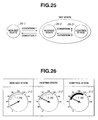
- FIG. 25 and 26 there is shown an eighth embodiment of the vehicle traveling control system with the state display apparatus according to the present invention.
- the eighth embodiment is arranged such that the traveling control section takes a non-set state (control standby mode), a resting state (control rest mode), and a control state (traveling control mode) as a control mode, like as a lane keeping control for applying a torque to a steering so as to steer the host vehicle along a road lane upon recognizing lane marks by means of an image processing.
- the display content determined section 1-8 is arranged such that the appearance of the speed range is changed in color, design or brightness according to the control mode which is selected from the control standby mode, the control rest mode, and the traveling control mode, and is displayed on the speed range display section 1-96.
- Fig. 25 shows the relationship among a non-set state 26-1, a resting state 26-2,and a control state 26-3 which are changed according to conditions I to IV.
- the resting state 26-2 is a condition that the control is temporally rested for reasons that the driver is manipulating the steering wheel under a condition that the control is set and no lane marker is recognized.
- the control state 26-3 is a condition that the control is executed when the control is set, when the lane marker is recognized and when the driver is not manipulating the steering wheel.
- the condition I is established when set switch SW S is pushed under a condition that the vehicle is traveling within a predetermined vehicle speed. By the establishment of the condition I, the mode is transited from the non-set state 26-1 to the set state including the resting state 26-2 and the control state 26-3.
- the condition II is established when cancel switch SW C is pushed under the set state or when the brake pedal is increasingly depressed under the set state. By the establishment of the condition II, the mode is transited from the set state including the resting state 26-2 and the control state 26-3 to the non-set state 26-1.
- condition III is established when the lane marker is recognized and when the steering wheel is not manipulated by the driver and when winkers is inoperative. By the establishment of the condition III, the mode is transited form the resting state 26-2 to the control state 26-3.
- the condition IV is established when the lane marker is not recognized under the control state 26-3 or when the driver manipulates at least one of the steering wheel and the winker. By the establishment of the condition IV, the mode is transited from the control state 26-3 to the resting state 26-2.
- a ninth embodiment of the vehicle traveling control system with the state display apparatus is shown a ninth embodiment of the vehicle traveling control system with the state display apparatus according to the present invention.
- the ninth embodiment is arranged such that when the traffic-congestion following control is cancelled by lowering of the vehicle speed to a vehicle speed smaller than the controlled vehicle speed (low-cut) and when the vehicle speed is then increased within a control-condition speed range by increasingly depressing the accelerator pedal before the vehicle stops, the control is automatically restarted.
- the display content determining section 1-8 of traveling controller 30 outputs a display command to the speed range display section 1-96 so as to blink the display of the control-condition speed range until the vehicle is stopped or the control is restarted or cancelled after the control is cancelled due to the low-cut of the vehicle speed.
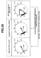
- Fig. 27 shows a flowchart of the speed range display content determining process executed by the display content determining section 1-8 of traveling controller 30 employed in the ninth embodiment according to the present invention.
- traveling controller 30 determines whether main switch SW M is turned on or not. When the determination at step S2801 is negative, the routine proceeds to step S2802 wherein controller 30 turns off the display of the speed range displayed on the speed range display section 1-96. Then, the routine proceeds to an end block to terminate the present routine. When the determination at step S2801 is affirmative, the routine proceeds to step S2803.
- controller 30 determines whether the control is now being executed or not. When the determination at step S2803 is negative, the routine proceeds to step S2804 wherein controller 30 displays the set-condition speed range. Then, the routine proceeds to the end block. When the determination at step S2803 is affirmative, the routine proceeds to step S2805.
- controller 30 displays (turns on) the control-condition speed range at the speed range display section 1-96.
- controller 30 determines whether the low-cut is executed or not. When the determination at step S2806 is negative, the routine jumps to the end block. When the determination at step S2806 is affirmative, the routine proceeds to step S2807.
- controller 30 commands the speed range display section 1-96 to blink the control-condition speed range.
- controller 30 determines whether or not the control is cancelled due to the braking operation of the driver. When the determination at step S2808 is affirmative, the routine proceeds to step S2809. When the determination at step S2808 is negative, the routine proceeds to step S2810.
- controller commands the speed range display section 1-96 to display the set-condition speed range. Then the routine proceeds to the end block.
- controller 30 determines whether or not the control is restarted due to the increasing depressing of the accelerator pedal by the driver.
- the routine proceeds to step S2811 wherein controller 30 commands speed range display section 1-96 to display the control-condition speed range. Then, the routine proceeds to the end block.
- the routine returns to step S2807.
- step S2801 When main switch SW M is pushed and when the low-cut of the vehicle speed is not executed during the control where set switch SW S is pushed, the routine of Fig. 27 proceeds in the order of step S2801 ⁇ step S2803 ⁇ step S2805 ⁇ step S2806 ⁇ End block. Accordingly, the control-condition speed range is displayed on the speed range display section 1-96 of speedometer 2-2 while changing its appearance different from that in the non-control state, as shown by the indication of the inching control state of Fig. 28.
- step S2801 When main switch SW M is pushed and when the low-cut is executed during the control where set switch SW S is pushed, the routine of Fig. 27 proceeds in the order of step S2801 ⁇ step S2803 ⁇ step S2805 ⁇ step S2806 ⁇ step S2806 ⁇ step S2807. Accordingly, the control-condition speed range is displayed while blinking on the speed range display section 1-96 of speedometer 2-2, as shown by the indication of the state between low-cut and stop in Fig. 28.
- step S2801 When the control is canceled in reply to the braking operation after the low-cut is executed, the routine of Fig. 27 proceeds in the order of step S2801 ⁇ step S2803 ⁇ step S2805 ⁇ step S2806 ⁇ step S2807 ⁇ step S2808 ⁇ step S2809. Accordingly, the display content of the speed range is changed from the blinking display of the control-condition speed range to the display of the set-condition speed range during the non-control state.
- step S2801 When the control is restarted by the increasing depression of the accelerator pedal after the low-cut is executed, the routine of Fig. 27 proceeds in the order of step S2801 ⁇ step S2803 ⁇ step S2805 ⁇ step S2806 ⁇ step S2807 ⁇ step S2808 ⁇ step S2810 ⁇ step S2811. Accordingly, the display content of the speed range is changed from the blinking display of the speed range corresponding to a period between the low-cut and the vehicle stop to the control-condition speed range during the inching control.
- the appearance of the display of the speed range is blinked so as to be different from the appearance of the normal display. Therefore, the driver can recognize the control condition inherent in the traffic-congestion following control system in that the control may be automatically restarted even when the low-cut is executed.
- the traffic-congestion following control system is arranged such that the inter-vehicle distance control is executed until the extremely low speed and that the vehicle is stopped by the control when a preceding vehicle is stopped and that the restart of the following control subsequent to the temporal stop of the vehicle is achieved by the driver's operation.
- the display content determining section 1-8 is arranged to display the set-condition speed range and the control-condition speed range and to command the speed range display section 1-96 to display only the speed corresponding to 0km/h during when the vehicle is stopped by the control.
- Fig. 29 shows a transition relationship among the control modes of the control content determining section 1-5.
- Control standby mode 30-1 is selected when main switch SW M is turned on from an OFF state.
- Traveling controller 30 calculates the command throttle opening and/or the command brake fluid pressure so as to bring the measured inter-vehicle distance L to the target inter-vehicle distance L* when the control system recognizes a preceding vehicle. Traveling controller 30 calculates the command throttle opening and/or the command brake fluid pressure so as to bring the measured vehicle speed closer to the target vehicle speed when the system recognizes no preceding vehicle.
- Traveling controller 30 controls the brake fluid pressure at a predetermined fluid pressure in order to keep the vehicle stop condition.
- One of these four control modes is executed according to the following transition conditions I to IX.
- Condition I is established when set switch SW S is pushed under a condition that the vehicle is traveling within a predetermined vehicle speed in D range. By the establishment of the condition I, the control mode is transited from control standby mode 30-1 to following mode 30-2.
- Condition II is established when the accelerator pedal is depressed under a condition of following mode 30-2. By the establishment of the condition II, the control mode is transited from following mode 30-2 to control rest mode 30-3.
- Condition III is established when the accelerator pedal is increasingly depressed during control rest mode 30-3. By the establishment of the condition III, the control mode is transited from control rest mode 30-3 to following mode 30-2.
- Condition IV is established when cancel switch SW C is pushed during the following mode. By the establishment of the condition IV, the control mode is transited from following mode 30-2 to control standby mode 30-1.
- Condition V is established when cancel switch SW C is pushed, shifting operation is executed or the vehicle speed becomes greater than a predetermined speed under a condition that the vehicle is accelerated during the control rest mode.
- the control mode is transited from control rest mode 30-3 to control standby mode 30-1.
- Condition VI is established when the inter-vehicle distance to a preceding vehicle is smaller than a predetermined value and the vehicle speed is lower than or equal to a predetermined speed, or when traveling controller 30 loses the preceding vehicle during a traveling at a speed lower than or equal to the predetermined speed.
- the control mode is transited from automatic stop mode 30-4 to the following mode 30-2.
- Condition VII is established when the vehicle speed becomes greater than the predetermined value by increasingly depressing accelerator pedal 14 under a condition that the vehicle stop condition is maintained by the control. By the establishment of condition VII, the control mode is transited from automatic stop mode 30-4 to following mode 30-2.
- Condition VIII is established when set switch SW S is pushed under a condition that the brake pedal is not depressed during D range, such as when the vehicle is stopping by the parking brake activation, or when the vehicle inches at an extremely low speed lower than a predetermined speed.
- the control mode is transited from the control standby mode 30-1 to the automatic stop mode 30-4.
- Condition IX is established when cancel switch SW C is pushed during the automatic stop or when the shift operation is executed or the brake pedal is increasingly depressed. By the establishment of the condition IX, the control mode is transited from the automatic stop mode 30-4 to the control standby mode 30-1.
- control standby mode 30-1 that is, when the main switch SW M is pushed and when set switch SW S is not pushed, the set-condition speed range is displayed at the speed range display section 1-96 of speedometer 2-2, as shown by the control standby state of Fig. 30.
- the driver can easily recognize that the vehicle is stopped in reply to the stop of the preceding vehicle and this stop of the host vehicle is inherent in the control state of the traffic-congestion following control system.
- 31 is arranged to comprise a low speed ranged display section, a high speed range display section, and a steady-state display section and to display a speed range of the set condition at the low speed range display section and to display the control-condition speed range at the high-speed range display section so as to be different from the low-speed range display section in appearance.
Landscapes
- Engineering & Computer Science (AREA)
- Transportation (AREA)
- Mechanical Engineering (AREA)
- Chemical & Material Sciences (AREA)
- Combustion & Propulsion (AREA)
- Automation & Control Theory (AREA)
- Human Computer Interaction (AREA)
- Controls For Constant Speed Travelling (AREA)
- Instrument Panels (AREA)
- Control Of Vehicle Engines Or Engines For Specific Uses (AREA)
- Traffic Control Systems (AREA)
Applications Claiming Priority (2)
| Application Number | Priority Date | Filing Date | Title |
|---|---|---|---|
| JP2001078370A JP4066609B2 (ja) | 2001-03-19 | 2001-03-19 | 車両用走行制御装置の状態表示装置 |
| JP2001078370 | 2001-03-19 |
Publications (3)
| Publication Number | Publication Date |
|---|---|
| EP1245427A2 true EP1245427A2 (de) | 2002-10-02 |
| EP1245427A3 EP1245427A3 (de) | 2004-11-17 |
| EP1245427B1 EP1245427B1 (de) | 2007-01-10 |
Family
ID=18934994
Family Applications (1)
| Application Number | Title | Priority Date | Filing Date |
|---|---|---|---|
| EP02250983A Expired - Lifetime EP1245427B1 (de) | 2001-03-19 | 2002-02-13 | Geschwindigkeitssteuerung mit Zustandsanzeige für ein Fahrzeug |
Country Status (4)
| Country | Link |
|---|---|
| US (1) | US6658344B2 (de) |
| EP (1) | EP1245427B1 (de) |
| JP (1) | JP4066609B2 (de) |
| DE (1) | DE60217430T2 (de) |
Cited By (8)
| Publication number | Priority date | Publication date | Assignee | Title |
|---|---|---|---|---|
| EP1652720A1 (de) * | 2004-10-29 | 2006-05-03 | Audi Ag | Geschwindigkeitssteuervorrichtung und Verfahren zum Steuern der Geschwindigkeit eines Fahrzeugs |
| WO2006122866A1 (de) * | 2005-05-17 | 2006-11-23 | Robert Bosch Gmbh | Anzeigevorrichtung für einen geschwindigkeitsregler mit stop & go funktion |
| DE102005057636A1 (de) * | 2005-12-02 | 2007-06-06 | Volkswagen Ag | Kraftfahrzeug |
| WO2009103388A1 (de) * | 2008-02-22 | 2009-08-27 | Daimler Ag | Verfahren zur unterstützung des fahrers eines fahrzeugs bei der fahrzeugführung |
| EP1900586A3 (de) * | 2006-09-14 | 2009-10-14 | Robert Bosch Gmbh | Abstandsregelvorrichtung mit Zielobjektanzeige |
| FR2995860A1 (fr) * | 2012-09-25 | 2014-03-28 | Peugeot Citroen Automobiles Sa | Systeme de visualisation de l'etat d'un dispositif d'alerte de franchissement involontaire de ligne d'un vehicule automobile |
| EP3395652A1 (de) * | 2017-04-27 | 2018-10-31 | Valeo Schalter und Sensoren GmbH | Fahrassistenzsystem für ein fahrzeug mit einem ausparkassistenten und einem langsamfahr-folgeassistenten |
| JP2020183226A (ja) * | 2014-09-30 | 2020-11-12 | エイディシーテクノロジー株式会社 | 自動運転制御装置及び車両 |
Families Citing this family (73)
| Publication number | Priority date | Publication date | Assignee | Title |
|---|---|---|---|---|
| JP3646660B2 (ja) * | 2001-03-26 | 2005-05-11 | 日産自動車株式会社 | 車両用追従走行制御装置 |
| US6591168B2 (en) | 2001-08-31 | 2003-07-08 | Intellisist, Inc. | System and method for adaptable mobile user interface |
| DE10149090A1 (de) * | 2001-10-05 | 2003-04-17 | Bosch Gmbh Robert | Geschwindigkeitsregler mit Anzeigeeinrichtung |
| DE10218017A1 (de) * | 2002-04-23 | 2003-11-06 | Bosch Gmbh Robert | Verfahren zur Geschwindigkeits- und Abstandsregelung bei Kraftfahrzeugen |
| US7096109B2 (en) * | 2002-11-12 | 2006-08-22 | Hitachi, Ltd. | Adaptive cruise control system |
| DE10303611A1 (de) * | 2003-01-30 | 2004-08-12 | Robert Bosch Gmbh | Geschwindigkeitsregler mit mehreren Betriebsmodi |
| US7642959B2 (en) * | 2003-03-21 | 2010-01-05 | Global Locate, Inc. | Method and apparatus for processing satellite signals at a satellite positioning system receiver |
| JPWO2004102222A1 (ja) * | 2003-05-13 | 2006-07-13 | 富士通株式会社 | 物体検出装置、物体検出方法、物体検出プログラム、距離センサ |
| JP2005230524A (ja) * | 2004-01-20 | 2005-09-02 | Yoshitani Kikai Seisakusho:Kk | 消防ポンプ用表示器、消防ポンプ用制御装置、及び消防ポンプ車 |
| JP4161938B2 (ja) * | 2004-06-01 | 2008-10-08 | トヨタ自動車株式会社 | 走行制御装置 |
| JP4082388B2 (ja) * | 2004-06-01 | 2008-04-30 | トヨタ自動車株式会社 | 走行制御装置 |
| US7974778B2 (en) * | 2004-09-17 | 2011-07-05 | Honda Motor Co., Ltd. | Vehicular control object determination system and vehicular travel locus estimation system |
| KR100668922B1 (ko) * | 2004-10-15 | 2007-01-12 | 엘지전자 주식회사 | 네비게이션 시스템의 엘씨디 밝기 제어 방법 |
| JP5308673B2 (ja) * | 2004-12-14 | 2013-10-09 | バイエリッシェ モートーレン ウエルケ アクチエンゲゼルシャフト | 車両内の少なくとも一つのモバイル端末の利用システム |
| JP4617172B2 (ja) * | 2005-02-17 | 2011-01-19 | 本田技研工業株式会社 | 移動体 |
| US7627413B2 (en) * | 2005-03-31 | 2009-12-01 | Nissan Technical Center North America, Inc. | System and methods utilizing slope of target speed for cooperative speed for cooperative speed control system |
| WO2006124130A1 (en) * | 2005-03-31 | 2006-11-23 | Energycs | Method and system for retrofitting a full hybrid to be a plug-in hybrid |
| JP4674491B2 (ja) * | 2005-05-20 | 2011-04-20 | 日産自動車株式会社 | 先行車追従制御装置 |
| DE102005029444A1 (de) * | 2005-06-24 | 2006-12-28 | Robert Bosch Gmbh | Vorrichtung zum Unterstützen eines Führens eines Fahrzeugs und Verfahren zum Betreiben der Vorrichtung |
| US7410447B2 (en) * | 2005-10-31 | 2008-08-12 | General Motors Corporation | Vehicle speed control system |
| US11279233B2 (en) | 2005-11-17 | 2022-03-22 | Invently Automotive Inc. | Electric vehicle power management system |
| US11267338B2 (en) | 2005-11-17 | 2022-03-08 | Invently Automotive Inc. | Electric vehicle power management system |
| US11267339B2 (en) | 2005-11-17 | 2022-03-08 | Invently Automotive Inc. | Vehicle power management system |
| US11279234B2 (en) | 2005-11-17 | 2022-03-22 | Invently Automotive Inc. | Vehicle power management system |
| DE102006011481A1 (de) * | 2006-03-13 | 2007-09-20 | Robert Bosch Gmbh | Verfahren und Vorrichtung zum Unterstützen eines Führens eines Fahrzeugs |
| DE102006020063A1 (de) * | 2006-04-29 | 2007-10-31 | Dr.Ing.H.C. F. Porsche Ag | Fahrgeschwindigkeitsregelungseinrichtung |
| JP2007302028A (ja) * | 2006-05-09 | 2007-11-22 | Fujitsu Ten Ltd | 速度設定システム |
| DE102006047141A1 (de) * | 2006-10-05 | 2008-04-10 | Robert Bosch Gmbh | Verfahren und Vorrichtung zur Bestimmung eines Zielzustands |
| DE102006060554A1 (de) * | 2006-12-21 | 2008-06-26 | Bayerische Motoren Werke Ag | Lenkrad für ein Kraftfahrzeug und Kraftfahrzeug |
| US7979199B2 (en) * | 2007-01-10 | 2011-07-12 | Honeywell International Inc. | Method and system to automatically generate a clearance request to deviate from a flight plan |
| US20090005948A1 (en) * | 2007-06-28 | 2009-01-01 | Faroog Abdel-Kareem Ibrahim | Low speed follow operation and control strategy |
| US8121772B2 (en) * | 2007-10-23 | 2012-02-21 | Nissan Motor Co., Ltd. | Headway distance maintenance supporting device and method |
| IL187029A0 (en) * | 2007-10-30 | 2008-02-09 | Haim Brody | Speed deviation indicator |
| DE102008061649A1 (de) * | 2008-06-11 | 2009-12-17 | Volkswagen Ag | Fahrerassistenzsystem und Verfahren zur Unterstützung eines Kraftfahrzeugführers |
| JP5471301B2 (ja) * | 2009-10-27 | 2014-04-16 | 株式会社デンソー | 車両システム、交通システム |
| JP5521821B2 (ja) * | 2010-06-23 | 2014-06-18 | 株式会社デンソー | 運転支援システム |
| JP2012101755A (ja) * | 2010-11-12 | 2012-05-31 | Denso Corp | 車速制御システム |
| US8744666B2 (en) * | 2011-07-06 | 2014-06-03 | Peloton Technology, Inc. | Systems and methods for semi-autonomous vehicular convoys |
| JP2013056597A (ja) * | 2011-09-07 | 2013-03-28 | Fuji Heavy Ind Ltd | 車両用表示装置 |
| CN102501766A (zh) * | 2011-10-14 | 2012-06-20 | 成都市翻鑫家科技有限公司 | 车速报警装置 |
| US20130135091A1 (en) * | 2011-11-29 | 2013-05-30 | Richard Booth Platt | Indicator system for automotive vehicle |
| JP6163718B2 (ja) * | 2012-08-30 | 2017-07-19 | トヨタ自動車株式会社 | 車両制御装置 |
| JP6055277B2 (ja) * | 2012-11-06 | 2016-12-27 | 川崎重工業株式会社 | 乗物用メータ表示装置 |
| JPWO2014102884A1 (ja) * | 2012-12-28 | 2017-01-12 | トヨタ自動車株式会社 | 車両の制御装置 |
| GB2511841B (en) * | 2013-03-15 | 2015-02-25 | Jaguar Land Rover Ltd | Vehicle speed control system and method |
| JP2015009777A (ja) * | 2013-07-02 | 2015-01-19 | 富士重工業株式会社 | クルーズコントロール装置 |
| KR20150008253A (ko) * | 2013-07-11 | 2015-01-22 | 현대자동차주식회사 | 차량의 발진 제어 장치 및 방법 |
| JP6156077B2 (ja) * | 2013-11-08 | 2017-07-05 | トヨタ自動車株式会社 | 車両制御装置 |
| GB2553688B (en) * | 2014-02-18 | 2018-09-12 | Jaguar Land Rover Ltd | Control system and method |
| US9457662B2 (en) * | 2014-07-09 | 2016-10-04 | Visteon Global Technologies, Inc. | Presenting a dynamic range based on an operating parameter of a vehicle |
| KR101646340B1 (ko) | 2014-08-27 | 2016-08-05 | 현대자동차주식회사 | 차량정보 표시장치 및 그 표시방법 |
| US9393963B2 (en) | 2014-09-19 | 2016-07-19 | Paccar Inc | Predictive cruise control system with advanced operator control and feedback |
| US10026324B2 (en) | 2014-11-04 | 2018-07-17 | Honeywell International Inc. | Systems and methods for enhanced adoptive validation of ATC clearance requests |
| JP6536340B2 (ja) | 2014-12-01 | 2019-07-03 | 株式会社デンソー | 画像処理装置 |
| DE102015000527B4 (de) * | 2015-01-17 | 2020-10-29 | Audi Ag | Verfahren zum Betrieb eines Kraftfahrzeugs mit einem längsführenden Fahrerassistenzsystem |
| US10054225B2 (en) | 2015-04-30 | 2018-08-21 | Cnh Industrial America Llc | Self-propelled off-road agricultural vehicle with a dynamically reconfiguring speed control and display system |
| US9637120B2 (en) * | 2015-06-24 | 2017-05-02 | Delphi Technologies, Inc. | Cognitive driver assist with variable assistance for automated vehicles |
| US9734744B1 (en) * | 2016-04-27 | 2017-08-15 | Joan Mercior | Self-reacting message board |
| US10232711B2 (en) * | 2016-06-03 | 2019-03-19 | Toyota Motor Engineering & Manufacturing North America, Inc. | Spatiotemporal displays for set speed deviation of a vehicle |
| US20180121071A1 (en) * | 2016-11-03 | 2018-05-03 | Ford Global Technologies, Llc | Vehicle display based on vehicle speed |
| CN106671776B (zh) * | 2016-12-09 | 2019-03-22 | 重庆长安汽车股份有限公司 | 基于驾驶员操作的车辆行驶速度控制系统及方法 |
| KR102014262B1 (ko) * | 2017-12-11 | 2019-08-26 | 엘지전자 주식회사 | 차량에 구비된 디스플레이 장치 및 디스플레이 장치의 제어방법 |
| US11059421B2 (en) | 2018-03-29 | 2021-07-13 | Honda Motor Co., Ltd. | Vehicle proximity system using heads-up display augmented reality graphics elements |
| DE102018206423A1 (de) * | 2018-04-25 | 2019-10-31 | Bayerische Motoren Werke Aktiengesellschaft | Aktivierung und Deaktivierung einer Fahrfunktion zum automatisierten Fahren mit Längs- und Querführung |
| DE102018212296A1 (de) * | 2018-06-21 | 2019-12-24 | Robert Bosch Gmbh | Verfahren zum Betreiben eines Fahrzeugs und Steuergerät |
| EP3671692A1 (de) * | 2018-12-19 | 2020-06-24 | Ningbo Geely Automobile Research & Development Co. Ltd. | Zeit für die durchfahrt eines fahrzeugzuges |
| AU2019100368B4 (en) * | 2019-01-25 | 2019-11-28 | Norman BOYLE | A driverless impact attenuating traffic management vehicle |
| US11823576B2 (en) * | 2019-02-04 | 2023-11-21 | Nec Corporation | Vehicle management device, vehicle management method, and storage medium having program stored therein |
| JP7112347B2 (ja) * | 2019-02-08 | 2022-08-03 | 本田技研工業株式会社 | 車両制御装置、車両制御方法、車両およびプログラム |
| JP7343438B2 (ja) * | 2020-04-02 | 2023-09-12 | トヨタ自動車株式会社 | 自律走行車両及び自律走行車両の運行管理装置 |
| JP7145185B2 (ja) * | 2020-09-23 | 2022-09-30 | 本田技研工業株式会社 | 表示装置、表示制御方法、およびプログラム |
| JP2022126240A (ja) * | 2021-02-18 | 2022-08-30 | トヨタ自動車株式会社 | 車両用表示装置 |
| US11869361B2 (en) * | 2021-04-01 | 2024-01-09 | Gm Cruise Holdings Llc | Coordinated multi-vehicle routing |
Citations (4)
| Publication number | Priority date | Publication date | Assignee | Title |
|---|---|---|---|---|
| DE19539799A1 (de) * | 1994-11-03 | 1996-05-09 | Volkswagen Ag | Informationseinrichtung für Kraftfahrzeuge |
| DE19620467A1 (de) * | 1996-05-21 | 1997-11-27 | Bayerische Motoren Werke Ag | Optisches Anzeigeverfahren für Fahrzeuge mit einem Geschwindigkeitsregler |
| DE19948612A1 (de) * | 1998-10-16 | 2000-04-20 | Denso Corp | Informationsvermittlungsvorrichtung für ein Automatisches Geschwindikeitsregelungssystem |
| EP1065090A2 (de) * | 1999-06-30 | 2001-01-03 | Nissan Motor Company, Limited | Abstandsbezogenes Fahrgeschwindigkeitsregelsystem mit Soll-Abtriebsdrehmomentsteuerung |
Family Cites Families (10)
| Publication number | Priority date | Publication date | Assignee | Title |
|---|---|---|---|---|
| US5838259A (en) * | 1992-02-05 | 1998-11-17 | Design Technology & Innovation Ltd. | Motor vehicle display system and ranging device |
| US6133852A (en) * | 1994-08-05 | 2000-10-17 | Design Technology | Motor vehicle system and ranging device |
| JPH08192663A (ja) | 1995-01-20 | 1996-07-30 | Mitsubishi Motors Corp | 車両の走行制御装置における表示装置 |
| JPH08253058A (ja) * | 1995-03-20 | 1996-10-01 | Aisin Seiki Co Ltd | 移動体速度制御装置 |
| JP4209951B2 (ja) | 1995-08-07 | 2009-01-14 | 日産自動車株式会社 | 自動車用表示装置 |
| JPH10252520A (ja) * | 1997-03-14 | 1998-09-22 | Nissan Diesel Motor Co Ltd | 車速制限装置 |
| JP3755248B2 (ja) * | 1997-07-25 | 2006-03-15 | トヨタ自動車株式会社 | 車載表示装置 |
| JP3430883B2 (ja) * | 1997-10-13 | 2003-07-28 | オムロン株式会社 | 追従走行システムにおけるフェールセーフ装置 |
| JP2000238552A (ja) * | 1999-02-19 | 2000-09-05 | Yazaki Corp | 車両用計器及びその計器表示方法、計器表示プログラムを記憶した記録媒体 |
| JP2002234358A (ja) * | 2001-02-07 | 2002-08-20 | Honda Motor Co Ltd | 車両用追従走行制御装置 |
-
2001
- 2001-03-19 JP JP2001078370A patent/JP4066609B2/ja not_active Expired - Fee Related
-
2002
- 2002-02-13 EP EP02250983A patent/EP1245427B1/de not_active Expired - Lifetime
- 2002-02-13 DE DE60217430T patent/DE60217430T2/de not_active Expired - Lifetime
- 2002-02-15 US US10/075,614 patent/US6658344B2/en not_active Expired - Lifetime
Patent Citations (4)
| Publication number | Priority date | Publication date | Assignee | Title |
|---|---|---|---|---|
| DE19539799A1 (de) * | 1994-11-03 | 1996-05-09 | Volkswagen Ag | Informationseinrichtung für Kraftfahrzeuge |
| DE19620467A1 (de) * | 1996-05-21 | 1997-11-27 | Bayerische Motoren Werke Ag | Optisches Anzeigeverfahren für Fahrzeuge mit einem Geschwindigkeitsregler |
| DE19948612A1 (de) * | 1998-10-16 | 2000-04-20 | Denso Corp | Informationsvermittlungsvorrichtung für ein Automatisches Geschwindikeitsregelungssystem |
| EP1065090A2 (de) * | 1999-06-30 | 2001-01-03 | Nissan Motor Company, Limited | Abstandsbezogenes Fahrgeschwindigkeitsregelsystem mit Soll-Abtriebsdrehmomentsteuerung |
Cited By (9)
| Publication number | Priority date | Publication date | Assignee | Title |
|---|---|---|---|---|
| EP1652720A1 (de) * | 2004-10-29 | 2006-05-03 | Audi Ag | Geschwindigkeitssteuervorrichtung und Verfahren zum Steuern der Geschwindigkeit eines Fahrzeugs |
| WO2006122866A1 (de) * | 2005-05-17 | 2006-11-23 | Robert Bosch Gmbh | Anzeigevorrichtung für einen geschwindigkeitsregler mit stop & go funktion |
| DE102005057636A1 (de) * | 2005-12-02 | 2007-06-06 | Volkswagen Ag | Kraftfahrzeug |
| DE102005057636B4 (de) | 2005-12-02 | 2022-08-11 | Volkswagen Ag | Kraftfahrzeug |
| EP1900586A3 (de) * | 2006-09-14 | 2009-10-14 | Robert Bosch Gmbh | Abstandsregelvorrichtung mit Zielobjektanzeige |
| WO2009103388A1 (de) * | 2008-02-22 | 2009-08-27 | Daimler Ag | Verfahren zur unterstützung des fahrers eines fahrzeugs bei der fahrzeugführung |
| FR2995860A1 (fr) * | 2012-09-25 | 2014-03-28 | Peugeot Citroen Automobiles Sa | Systeme de visualisation de l'etat d'un dispositif d'alerte de franchissement involontaire de ligne d'un vehicule automobile |
| JP2020183226A (ja) * | 2014-09-30 | 2020-11-12 | エイディシーテクノロジー株式会社 | 自動運転制御装置及び車両 |
| EP3395652A1 (de) * | 2017-04-27 | 2018-10-31 | Valeo Schalter und Sensoren GmbH | Fahrassistenzsystem für ein fahrzeug mit einem ausparkassistenten und einem langsamfahr-folgeassistenten |
Also Published As
| Publication number | Publication date |
|---|---|
| JP4066609B2 (ja) | 2008-03-26 |
| US6658344B2 (en) | 2003-12-02 |
| EP1245427A3 (de) | 2004-11-17 |
| JP2002274217A (ja) | 2002-09-25 |
| EP1245427B1 (de) | 2007-01-10 |
| US20020133285A1 (en) | 2002-09-19 |
| DE60217430D1 (de) | 2007-02-22 |
| DE60217430T2 (de) | 2007-10-25 |
Similar Documents
| Publication | Publication Date | Title |
|---|---|---|
| EP1245427B1 (de) | Geschwindigkeitssteuerung mit Zustandsanzeige für ein Fahrzeug | |
| US20160304124A1 (en) | Vehicle control system | |
| US6332108B1 (en) | Vehicular run controlling apparatus and method for automotive vehicle | |
| EP2781722B1 (de) | Fahrassistenzvorrichtung | |
| CN100515817C (zh) | 在前车辆的跟踪巡航控制系统和方法 | |
| EP1818231A2 (de) | Fahrzeugsteuerungssystem | |
| JP2019101677A (ja) | 隊列走行システム | |
| US10983516B2 (en) | Vehicle control system | |
| US20180118208A1 (en) | Vehicle travel control apparatus | |
| JP2016222150A (ja) | 車両の制御装置 | |
| US20050137775A1 (en) | Vehicle driving support apparatus | |
| CN111688687B (zh) | 车辆行驶控制装置 | |
| CN110626344A (zh) | 车辆的控制装置 | |
| CN113825691B (zh) | 车辆的行驶控制方法及行驶控制装置 | |
| US20230373506A1 (en) | Vehicle Guidance System and Method for Operating a Driving Function According to Driver Data | |
| US20230347893A1 (en) | Platoon traveling system | |
| JP2019156355A (ja) | 車両制御装置 | |
| US20230141314A1 (en) | Driving force control device | |
| CN111391829A (zh) | 车辆的行驶控制装置 | |
| US20230373517A1 (en) | Vehicle Guidance System and Method for Operating a Driving Function in the Presence of a Contradiction With Map Data | |
| JP2019131131A (ja) | 車両の制御装置 | |
| JPH09323585A (ja) | 車両用減速警告装置 | |
| US20210387525A1 (en) | Method for improving the energy efficiency of a motor vehicle, motor vehicle, and computer-readable medium | |
| US20230286505A1 (en) | Driving assistance apparatus | |
| US20230147441A1 (en) | Driving force control device |
Legal Events
| Date | Code | Title | Description |
|---|---|---|---|
| PUAI | Public reference made under article 153(3) epc to a published international application that has entered the european phase |
Free format text: ORIGINAL CODE: 0009012 |
|
| 17P | Request for examination filed |
Effective date: 20020219 |
|
| AK | Designated contracting states |
Kind code of ref document: A2 Designated state(s): AT BE CH CY DE DK ES FI FR GB GR IE IT LI LU MC NL PT SE TR |
|
| AX | Request for extension of the european patent |
Free format text: AL;LT;LV;MK;RO;SI |
|
| PUAL | Search report despatched |
Free format text: ORIGINAL CODE: 0009013 |
|
| AK | Designated contracting states |
Kind code of ref document: A3 Designated state(s): AT BE CH CY DE DK ES FI FR GB GR IE IT LI LU MC NL PT SE TR |
|
| AX | Request for extension of the european patent |
Extension state: AL LT LV MK RO SI |
|
| AKX | Designation fees paid |
Designated state(s): DE FR GB |
|
| GRAP | Despatch of communication of intention to grant a patent |
Free format text: ORIGINAL CODE: EPIDOSNIGR1 |
|
| GRAS | Grant fee paid |
Free format text: ORIGINAL CODE: EPIDOSNIGR3 |
|
| GRAA | (expected) grant |
Free format text: ORIGINAL CODE: 0009210 |
|
| AK | Designated contracting states |
Kind code of ref document: B1 Designated state(s): DE FR GB |
|
| REG | Reference to a national code |
Ref country code: GB Ref legal event code: FG4D |
|
| REF | Corresponds to: |
Ref document number: 60217430 Country of ref document: DE Date of ref document: 20070222 Kind code of ref document: P |
|
| ET | Fr: translation filed | ||
| PLBE | No opposition filed within time limit |
Free format text: ORIGINAL CODE: 0009261 |
|
| STAA | Information on the status of an ep patent application or granted ep patent |
Free format text: STATUS: NO OPPOSITION FILED WITHIN TIME LIMIT |
|
| 26N | No opposition filed |
Effective date: 20071011 |
|
| REG | Reference to a national code |
Ref country code: FR Ref legal event code: PLFP Year of fee payment: 15 |
|
| PGFP | Annual fee paid to national office [announced via postgrant information from national office to epo] |
Ref country code: DE Payment date: 20160209 Year of fee payment: 15 |
|
| PGFP | Annual fee paid to national office [announced via postgrant information from national office to epo] |
Ref country code: FR Payment date: 20160108 Year of fee payment: 15 Ref country code: GB Payment date: 20160210 Year of fee payment: 15 |
|
| REG | Reference to a national code |
Ref country code: DE Ref legal event code: R119 Ref document number: 60217430 Country of ref document: DE |
|
| GBPC | Gb: european patent ceased through non-payment of renewal fee |
Effective date: 20170213 |
|
| REG | Reference to a national code |
Ref country code: FR Ref legal event code: ST Effective date: 20171031 |
|
| PG25 | Lapsed in a contracting state [announced via postgrant information from national office to epo] |
Ref country code: FR Free format text: LAPSE BECAUSE OF NON-PAYMENT OF DUE FEES Effective date: 20170228 Ref country code: DE Free format text: LAPSE BECAUSE OF NON-PAYMENT OF DUE FEES Effective date: 20170901 |
|
| PG25 | Lapsed in a contracting state [announced via postgrant information from national office to epo] |
Ref country code: GB Free format text: LAPSE BECAUSE OF NON-PAYMENT OF DUE FEES Effective date: 20170213 |