EP1237147A1 - Fussmaschine für eine Bass-Drum - Google Patents
Fussmaschine für eine Bass-Drum Download PDFInfo
- Publication number
- EP1237147A1 EP1237147A1 EP02004449A EP02004449A EP1237147A1 EP 1237147 A1 EP1237147 A1 EP 1237147A1 EP 02004449 A EP02004449 A EP 02004449A EP 02004449 A EP02004449 A EP 02004449A EP 1237147 A1 EP1237147 A1 EP 1237147A1
- Authority
- EP
- European Patent Office
- Prior art keywords
- return spring
- shaft
- pedal
- bearing
- spring
- Prior art date
- Legal status (The legal status is an assumption and is not a legal conclusion. Google has not performed a legal analysis and makes no representation as to the accuracy of the status listed.)
- Granted
Links
Images


Classifications
-
- G—PHYSICS
- G10—MUSICAL INSTRUMENTS; ACOUSTICS
- G10D—STRINGED MUSICAL INSTRUMENTS; WIND MUSICAL INSTRUMENTS; ACCORDIONS OR CONCERTINAS; PERCUSSION MUSICAL INSTRUMENTS; AEOLIAN HARPS; SINGING-FLAME MUSICAL INSTRUMENTS; MUSICAL INSTRUMENTS NOT OTHERWISE PROVIDED FOR
- G10D13/00—Percussion musical instruments; Details or accessories therefor
- G10D13/10—Details of, or accessories for, percussion musical instruments
- G10D13/11—Pedals; Pedal mechanisms
Definitions
- the invention relates to a pedal machine for percussion instruments with a Bearing base with columns extending upwards with bearings in which at least a mallet is held pivotably by means of at least one shaft and against the force of at least one return spring by means of a Pedal operated actuation mechanism is movable, each with one with a shaft operatively connected transmission element, which with the Return spring is connected.
- Such pedals are used to quickly play a drummer's foot and transfer it precisely to the percussion instrument, especially a bass drum.
- the foot machine is usually with a clamping device on Hoops attached to the bass drum.
- a foot pedal is for example known from DE 33 27 687 C2. This has a foot with towering of it Stands on, in their upper ends, for example via roller bearings, a keep horizontal wave.
- a sprocket and a non-rotating seat on this shaft Clamping head in which the mallet is held over the lower end of a shaft the impact pad is attached to the upper end of the shaft.
- the front end of a pedal engages over a bearing pin at one end Link chain, which is partially wrapped around the sprocket, and thus actuates the wave and consequently the flail movement.
- US 5,567,899 describes a double foot machine with two shafts, each are in operative connection with a return spring.
- One with the wave over a bushing of connected cams is provided with an opening in which a roller is pivotally mounted.
- the roll is extended with a suspension part the top of the spring is fixed.
- the lower end of the spring is with connected to a bracket on the column base and that via an adjusting element for Setting the desired tension of the return spring.
- This setting element comprises a threaded pin and a component for preventing rotation of the Threaded pin.
- the lower end of the spring is in a cross hole in the grub screw head swinging, while the grub screw rotates on the Bracket is mounted.
- the tension of the return spring determines the pressure that the drummer overcomes with his foot to pivot the drumstick and the speed at which the pedal flips back.
- the basic idea of the invention is the return spring by means of a pivotable lower spring bearing element - directly - to attach to the lower column part.
- the pivotable lower spring bearing element preferably comprises an adjusting element for setting the return spring tension, which also swivels.
- the setting element is therefore not rotation-free.
- the adjusting element preferably comprises a receiving part for a threaded pin, which is connected to the return spring.
- the receiving part itself has a tab on by means of a bearing around a cylindrical projection, for example a bolt, is pivotally arranged on the lower part of the column.
- the upper spring bearing element comprises a suspension element, in which the spring engages swinging.
- the suspension element comprises a Connection disc with an upper and lower part, being in the lower part a first transverse bore is introduced into the connecting disk, into which the upper one Swinging end of the return spring engages.
- a second cross hole with a bearing is introduced in a bolt, the axis of which is parallel to the shaft axis, is arranged.
- the transmission element comprises a connecting rod connected to a shaft end with downwardly extending hooks with which the bolt of the suspension element comes into engagement.
- the proposed pivotable attachment of the return spring can be used in all Types of foot pedals are used.
- FIG. 1 In the embodiment of a foot machine for percussion musical instruments shown in FIG. 1 it is a foot machine 1 with two flails 2, 3, via a two-part pedal 4 with two different actuation mechanisms 5, 6 are operated.
- the bearing base 7 of the foot machine 1 comprises a base plate 8, at its end 8a pointing towards the bass drum D.
- two columns 9 extending upwards from the base plate 8, 10 are detachably mounted by means of a screw connector 68.
- actuation mechanisms for the wave and thus the flail movement of all other types also in question, such as a chain drive.
- a reinforced plastic tape is preferably used as a traction device; this reinforcement is achieved, for example, by means of an integrated steel wire mesh or by means of an integrated second plastic, such as nylon.
- a chain drive is particularly recommended to use a toothed Roller chain that runs over a sprocket. To prevent annoying noise the sprocket is preferably padded when running from metal to metal.
- the actuation mechanisms are each using a separate pedal or operated using a two-part pedal - as shown here.
- both independently working shafts 13, 15 of the double foot pedal shown are rotatably connected to the shafts 67 and 66 (see FIG. 2) arranged clamping heads 16, 17, in each of which the flail 2, 3rd is held over the lower end of a shaft 18, 19, at the upper The end of the shock pad 20, 21 is arranged.
- two shafts 13, 15 two bearing elements 22, 23 or trestles are provided. These are on a corresponding recess 24 (see FIG. 3) one end 22a, 23a with a cross member 25 or with a traverse, here in Form a hexagonal rod connected, which or the parallel and vertically spaced below the shaft longitudinal axis on the columns 9, 10 by means of screw connections 40, 39 is mounted and extends between them.
- the two bearing elements 22, 23 take on their respective other ends 26b, 26a rolling bearings 28, 27 for the shafts 13 and 15.
- the outer ends 29, 30 Both shafts are rotatably connected to a connecting rod 31, 32, which is in operative connection with a return spring 33, 34 which is pivotable the lower end of a column 10, 9 is attached.
- the basic elements base plate 8 and columns 9, 10 form the bearing base 7.
- These columns 9, 10 essentially consist of a strut 9a, 10a and a receiving element 9b, 10b for a roller bearing 36, 35, here ball bearing together to hold the outer shaft ends 30, 29.
- To a counter camp for the other or here inner shaft ends 38, 37 to create two additional roller bearings 27, 28 are provided. These are part of the two Bearing elements 23, 22 on the cross member 25 and the hexagonal rod are attached.
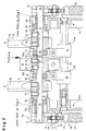
- the section shown on the right in FIG. 2 corresponds to the left section of FIG. 1.
- operating rod 41 a becomes a push rod 41b actuated, which in turn with a bushing or sleeve arranged on the shaft 15 66 interacts.
- the socket 66 is rotatably via grub screws 43, 44 with the shaft 15 connected.
- the inner end 38 of this rotated by the rod drive Shaft 15 is with a locking washer 45 in a groove against axial Moved secured.
- the section shown on the left in FIG. 2 corresponds to that shown on the right in FIG. 1 Area.
- the corresponding shaft 13 is at its inner end 37 two grub screws 46, 47 non-rotatably connected to the bush 65 of the connecting rod 12, which with the toothed plastic band 11, which with the front pedal part 4a or a projection 4c extending from this, in Active connection is established.
- the shaft 13 to be rotated in this way is also mounted by means of a bearing element 22 or a roller bearing 28. Between the two bearings 28, 35 holding the shaft 13 radially are the clamping head 16 with arranged upwardly extending mallet 2.
- the return spring 33 is at its end 48 facing the shaft 13 via a upper spring bearing element 75, which comprises a suspension element 69 for the spring, connected to a transmission element 70.
- the spring end 48 has an approximately semicircular ring 49 which is in a first transverse bore 50 of a connecting disc 51 is suspended.
- the connecting washer 51 has a second transverse bore 71, in which by means of a deep groove ball bearing 72 a bolt 52 is mounted, the bolt axis parallel to Wave axis runs.
- the suspension element 69 is made up of the connecting disk 51 and the bolt 52 together.
- the transmission element 70 is on Connecting rod 31, which is non-rotatably connected to the outer end 29 of the shaft 13.
- the Connecting rod 31 has two hooks 53, 54, into which suspension element 69 can be hung is.
- the return spring 33 is simple and quick Way out of the connecting rod 31.
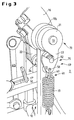
- the lower end 55 of the return spring 33 (see FIG. 4) is pivotable lower spring bearing element 74 arranged on the column base 10c.
- the lower Bearing element 74 comprises an adjusting element 73 or adjusting element for the spring tension with a grub screw 56 and a receiving part 57 for the grub screw 56, which comprises a tab 60.
- This tab can be swiveled over a Rolling bearing 61, in particular a ball bearing, around a from the foot 10c of the bearing column 10 protruding rigid bolts 62 are arranged. Adjusting the spring tension takes place via two screw nuts 63, 64 on the threaded pin 56. Im A head 59 is made in the head of the threaded pin 56, into which a ring 58 is suspended on the lower part of the spring 33.
Landscapes
- Physics & Mathematics (AREA)
- Engineering & Computer Science (AREA)
- Acoustics & Sound (AREA)
- Multimedia (AREA)
- Electrophonic Musical Instruments (AREA)
- Road Paving Machines (AREA)
Abstract
Description
- Fig. 1
- eine Schrägansicht einer Fußmaschine für Perkussions-Musikinstrumente;
- Fig. 2
- eine Schnittansicht des oberen Bereichs der Fußmaschine nach Fig. 1 mit detaillierter Darstellung des Aufhängungselementes einer Rückstellfeder;
- Fig. 3
- eine seitliche Detailansicht der Fußmaschine nach Fig. 1 zur Darstellung des Aufhängungselementes der Rückstellfeder;
- Fig. 4
- eine seitliche Detailansicht der Fußmaschine nach Fig. 1 zur Verdeutlichung des Einstellelements der Rückstellfeder.
Claims (8)
- Fußmaschine (1) für Perkussions-Instrumente
mit einem Lagersockel (7) mit sich nach oben erstreckenden Säulen (9, 10) mit Lagern (36, 35), in denen mindestens ein Schlegel (3, 2) mittels mindestens einer Welle (15, 13) verschwenkbar gehalten ist und entgegen der Kraft mindestens einer Rückstellfeder (34, 33) mittels eines durch ein Pedal (4) bedienbaren Betätigungsmechanismusses (5, 6) bewegbar ist,
mit jeweils einem mit einer Welle (15, 13) in Wirkverbindung stehenden Übertragungselement (70), das mit der Rückstellfeder (33, 34) verbunden ist,
dadurch gekennzeichnet, daß die Rückstellfeder (33) mittels eines schwenkbaren unteren Federlagerelementes (74) an einem unteren Säulenteil befestigt ist. - Fußmaschine nach Anspruch 1,
dadurch gekennzeichnet, daß das schwenkbare untere Federlagerelement (74) ein Einstellelement (73) für die Einstellung der Rückstellfederspannung umfaßt. - Fußmaschine nach Anspruch 1 oder 2,
dadurch gekennzeichnet, daß das Einstellelement (73) ein Aufnahmeteil (57) für einen Gewindestift (56) umfaßt, der mit der Rückstellfeder (33, 34) verbunden ist, und
das Aufnahmeteil (57) eine Lasche (60) aufweist, die mittels eines Lagers (61) um einen zylinderförmigen Vorsprung am unteren Säulenteil schwenkbar angeordnet ist. - Fußmaschine nach einem der Ansprüche 1 bis 3,
dadurch gekennzeichnet, daß die Rückstellfeder (33, 34) an ihrem zur Welle hinweisenden Ende (48) mittels eines oberen Federlagerelementes (75) lösbar an dem Übertragungselement (70) gelagert ist. - Fußmaschine nach Anspruch 4,
dadurch gekennzeichnet, daß das obere Federlagerelement (75) ein Aufhängungselement (69) umfaßt, an dem die Rückstellfeder (33, 34) schwingend aufgehängt ist. - Fußmaschine nach Anspruch 5,
dadurch gekennzeichnet, daß das Aufhängungselement (69) eine Verbindungsscheibe (51) mit einem oberen und unteren Teil umfaßt und
daß in den unteren Teil eine erste Querbohrung (50) eingebracht ist, in die das obere Ende (48) der Rückstellfeder (33) schwingend eingreift, und
daß in den oberen Teil eine zweite Querbohrung (71) mit einem Lager (72) eingebracht ist, in dem ein Bolzen (52), dessen Achse parallel zur Wellenachse verläuft, angeordnet ist. - Fußmaschine nach Anspruch 6,
dadurch gekennzeichnet, daß das Übertragungselement (70) ein mit einem Wellenende (29) verbundenes Pleuel (31) mit sich nach unten erstreckenden Haken (53, 54) umfaßt, mit denen der Bolzen (52) des Aufhängungselementes (69) in Eingriff kommt. - Fußmaschine nach einem der Ansprüche 3 bis 7,
dadurch gekennzeichnet, daß das Aufnahmeteil (57) mittels Schraubmuttern (63, 64) gegenüber dem Gewindestift (56) justierbar ist
und daß das untere Ende (55) der Rückstellfeder (33) in einer Bohrung (59) im Kopf des Gewindestiftes (56) eingehängt ist.
Applications Claiming Priority (2)
| Application Number | Priority Date | Filing Date | Title |
|---|---|---|---|
| DE10109942A DE10109942A1 (de) | 2001-03-01 | 2001-03-01 | Fußmaschine für Perkussions-Instrumente |
| DE10109942 | 2001-03-01 |
Publications (2)
| Publication Number | Publication Date |
|---|---|
| EP1237147A1 true EP1237147A1 (de) | 2002-09-04 |
| EP1237147B1 EP1237147B1 (de) | 2006-11-15 |
Family
ID=7675976
Family Applications (1)
| Application Number | Title | Priority Date | Filing Date |
|---|---|---|---|
| EP02004449A Expired - Lifetime EP1237147B1 (de) | 2001-03-01 | 2002-02-27 | Fussmaschine für eine Bass-Drum |
Country Status (2)
| Country | Link |
|---|---|
| EP (1) | EP1237147B1 (de) |
| DE (2) | DE10109942A1 (de) |
Cited By (1)
| Publication number | Priority date | Publication date | Assignee | Title |
|---|---|---|---|---|
| US8410346B2 (en) | 2010-09-29 | 2013-04-02 | Sonor Gmbh & Co. Kg | Bass-drum pedal assembly |
Citations (3)
| Publication number | Priority date | Publication date | Assignee | Title |
|---|---|---|---|---|
| DE352883C (de) * | 1921-03-12 | 1922-05-09 | William Fredrich Ludwig | Schlagzeug fuer Trommel und Zimbel |
| US5726370A (en) * | 1995-12-29 | 1998-03-10 | Pearl Musical Instrument Co. | Hoop clamping system for a bass drum pedal assembly |
| US6137040A (en) * | 1998-01-21 | 2000-10-24 | Hoshino Gakki Co., Ltd. | Spring structure for a drum pedal |
-
2001
- 2001-03-01 DE DE10109942A patent/DE10109942A1/de not_active Withdrawn
-
2002
- 2002-02-27 EP EP02004449A patent/EP1237147B1/de not_active Expired - Lifetime
- 2002-02-27 DE DE50208673T patent/DE50208673D1/de not_active Expired - Fee Related
Patent Citations (3)
| Publication number | Priority date | Publication date | Assignee | Title |
|---|---|---|---|---|
| DE352883C (de) * | 1921-03-12 | 1922-05-09 | William Fredrich Ludwig | Schlagzeug fuer Trommel und Zimbel |
| US5726370A (en) * | 1995-12-29 | 1998-03-10 | Pearl Musical Instrument Co. | Hoop clamping system for a bass drum pedal assembly |
| US6137040A (en) * | 1998-01-21 | 2000-10-24 | Hoshino Gakki Co., Ltd. | Spring structure for a drum pedal |
Cited By (1)
| Publication number | Priority date | Publication date | Assignee | Title |
|---|---|---|---|---|
| US8410346B2 (en) | 2010-09-29 | 2013-04-02 | Sonor Gmbh & Co. Kg | Bass-drum pedal assembly |
Also Published As
| Publication number | Publication date |
|---|---|
| EP1237147B1 (de) | 2006-11-15 |
| DE50208673D1 (de) | 2006-12-28 |
| DE10109942A1 (de) | 2002-09-19 |
Similar Documents
| Publication | Publication Date | Title |
|---|---|---|
| EP1237145B1 (de) | Fussmaschine für eine Bass-Drum | |
| DE3521794C2 (de) | ||
| DE69725418T2 (de) | Hintere Gangschaltung für Fahrrad | |
| EP0350748B1 (de) | Betätigungseinrichtung für ein Federelement an einem verstellbaren Stuhl | |
| DE69633749T2 (de) | Modulare Scheibenbremse sowie Betätigungshebel hierfür | |
| DE69308783T2 (de) | Befestigungseinrichtung für Räder, insbesondere für Rollschuhe | |
| DE3819179C2 (de) | ||
| DE19720375B4 (de) | Trommel-Schlagvorrichtung | |
| DE3537203A1 (de) | Arbeitsstuhl mit neigungsmechanik von sitzschale und rueckenlehne | |
| CH690019A5 (de) | Traggestell für einen Stuhl, insbesondere für einen in der Höhe und Neigung verstellbaren Bürostuhl. | |
| EP0485868A1 (de) | Stuhl, insbesondere Bürostuhl | |
| DE102018106119A1 (de) | Fahrradkomponentenbetätigungsvorrichtung | |
| DE3802560A1 (de) | Umwerfer fuer ein fahrrad | |
| EP0700487A1 (de) | Scheibenbremse, insbesondere für fahrzeuge | |
| DE3621043C2 (de) | ||
| DE3621042C2 (de) | ||
| DE3318949C2 (de) | ||
| DE10000879B4 (de) | Baumständer, insbesondere Christbaumständer | |
| DE2462892C2 (de) | Selbsttätige Nachstellvorrichtung für Fahrzeug-Außenbandbremsen | |
| EP1358783A1 (de) | Gefederte Halterungsanordnung und verstellbare Schwenkvorrichtung für eine solche | |
| EP1237147B1 (de) | Fussmaschine für eine Bass-Drum | |
| DE3819346A1 (de) | Bremsfederkupplung fuer stellgetriebe, insbesondere von sitzstellvorrichtungen, vorzugsweise in kraftfahrzeugen | |
| DE2108441B2 (de) | Zeichentisch | |
| DE102008006242A1 (de) | Tretroller, Skateboard oder ähnliches Fahrzeug mit einstellbarer Lenkung | |
| DE1206748B (de) | Wechselgetriebe mit Kettenumschaltung fuer Fahrraeder od. dgl. |
Legal Events
| Date | Code | Title | Description |
|---|---|---|---|
| PUAI | Public reference made under article 153(3) epc to a published international application that has entered the european phase |
Free format text: ORIGINAL CODE: 0009012 |
|
| AK | Designated contracting states |
Kind code of ref document: A1 Designated state(s): AT BE CH CY DE DK ES FI FR GB GR IE IT LI LU MC NL PT SE TR |
|
| AX | Request for extension of the european patent |
Free format text: AL;LT;LV;MK;RO;SI |
|
| 17P | Request for examination filed |
Effective date: 20030220 |
|
| AKX | Designation fees paid |
Designated state(s): DE FR GB IT |
|
| 17Q | First examination report despatched |
Effective date: 20050506 |
|
| GRAP | Despatch of communication of intention to grant a patent |
Free format text: ORIGINAL CODE: EPIDOSNIGR1 |
|
| GRAS | Grant fee paid |
Free format text: ORIGINAL CODE: EPIDOSNIGR3 |
|
| GRAA | (expected) grant |
Free format text: ORIGINAL CODE: 0009210 |
|
| AK | Designated contracting states |
Kind code of ref document: B1 Designated state(s): DE FR GB IT |
|
| PG25 | Lapsed in a contracting state [announced via postgrant information from national office to epo] |
Ref country code: IT Free format text: LAPSE BECAUSE OF FAILURE TO SUBMIT A TRANSLATION OF THE DESCRIPTION OR TO PAY THE FEE WITHIN THE PRESCRIBED TIME-LIMIT;WARNING: LAPSES OF ITALIAN PATENTS WITH EFFECTIVE DATE BEFORE 2007 MAY HAVE OCCURRED AT ANY TIME BEFORE 2007. THE CORRECT EFFECTIVE DATE MAY BE DIFFERENT FROM THE ONE RECORDED. Effective date: 20061115 |
|
| REG | Reference to a national code |
Ref country code: GB Ref legal event code: FG4D Free format text: NOT ENGLISH |
|
| REF | Corresponds to: |
Ref document number: 50208673 Country of ref document: DE Date of ref document: 20061228 Kind code of ref document: P |
|
| GBV | Gb: ep patent (uk) treated as always having been void in accordance with gb section 77(7)/1977 [no translation filed] |
Effective date: 20061115 |
|
| EN | Fr: translation not filed | ||
| EN | Fr: translation not filed | ||
| PLBE | No opposition filed within time limit |
Free format text: ORIGINAL CODE: 0009261 |
|
| STAA | Information on the status of an ep patent application or granted ep patent |
Free format text: STATUS: NO OPPOSITION FILED WITHIN TIME LIMIT |
|
| 26N | No opposition filed |
Effective date: 20070817 |
|
| PG25 | Lapsed in a contracting state [announced via postgrant information from national office to epo] |
Ref country code: GB Free format text: LAPSE BECAUSE OF FAILURE TO SUBMIT A TRANSLATION OF THE DESCRIPTION OR TO PAY THE FEE WITHIN THE PRESCRIBED TIME-LIMIT Effective date: 20061115 |
|
| PG25 | Lapsed in a contracting state [announced via postgrant information from national office to epo] |
Ref country code: FR Free format text: LAPSE BECAUSE OF FAILURE TO SUBMIT A TRANSLATION OF THE DESCRIPTION OR TO PAY THE FEE WITHIN THE PRESCRIBED TIME-LIMIT Effective date: 20070629 |
|
| PG25 | Lapsed in a contracting state [announced via postgrant information from national office to epo] |
Ref country code: FR Free format text: LAPSE BECAUSE OF FAILURE TO SUBMIT A TRANSLATION OF THE DESCRIPTION OR TO PAY THE FEE WITHIN THE PRESCRIBED TIME-LIMIT Effective date: 20061115 |
|
| PGFP | Annual fee paid to national office [announced via postgrant information from national office to epo] |
Ref country code: DE Payment date: 20090219 Year of fee payment: 8 |
|
| PG25 | Lapsed in a contracting state [announced via postgrant information from national office to epo] |
Ref country code: DE Free format text: LAPSE BECAUSE OF NON-PAYMENT OF DUE FEES Effective date: 20100901 |