EP1237147A1 - Pedal device for a bass-drum - Google Patents
Pedal device for a bass-drum Download PDFInfo
- Publication number
- EP1237147A1 EP1237147A1 EP02004449A EP02004449A EP1237147A1 EP 1237147 A1 EP1237147 A1 EP 1237147A1 EP 02004449 A EP02004449 A EP 02004449A EP 02004449 A EP02004449 A EP 02004449A EP 1237147 A1 EP1237147 A1 EP 1237147A1
- Authority
- EP
- European Patent Office
- Prior art keywords
- return spring
- shaft
- pedal
- bearing
- spring
- Prior art date
- Legal status (The legal status is an assumption and is not a legal conclusion. Google has not performed a legal analysis and makes no representation as to the accuracy of the status listed.)
- Granted
Links
Images


Classifications
-
- G—PHYSICS
- G10—MUSICAL INSTRUMENTS; ACOUSTICS
- G10D—STRINGED MUSICAL INSTRUMENTS; WIND MUSICAL INSTRUMENTS; ACCORDIONS OR CONCERTINAS; PERCUSSION MUSICAL INSTRUMENTS; AEOLIAN HARPS; SINGING-FLAME MUSICAL INSTRUMENTS; MUSICAL INSTRUMENTS NOT OTHERWISE PROVIDED FOR
- G10D13/00—Percussion musical instruments; Details or accessories therefor
- G10D13/10—Details of, or accessories for, percussion musical instruments
- G10D13/11—Pedals; Pedal mechanisms
Definitions
- the invention relates to a pedal machine for percussion instruments with a Bearing base with columns extending upwards with bearings in which at least a mallet is held pivotably by means of at least one shaft and against the force of at least one return spring by means of a Pedal operated actuation mechanism is movable, each with one with a shaft operatively connected transmission element, which with the Return spring is connected.
- Such pedals are used to quickly play a drummer's foot and transfer it precisely to the percussion instrument, especially a bass drum.
- the foot machine is usually with a clamping device on Hoops attached to the bass drum.
- a foot pedal is for example known from DE 33 27 687 C2. This has a foot with towering of it Stands on, in their upper ends, for example via roller bearings, a keep horizontal wave.
- a sprocket and a non-rotating seat on this shaft Clamping head in which the mallet is held over the lower end of a shaft the impact pad is attached to the upper end of the shaft.
- the front end of a pedal engages over a bearing pin at one end Link chain, which is partially wrapped around the sprocket, and thus actuates the wave and consequently the flail movement.
- US 5,567,899 describes a double foot machine with two shafts, each are in operative connection with a return spring.
- One with the wave over a bushing of connected cams is provided with an opening in which a roller is pivotally mounted.
- the roll is extended with a suspension part the top of the spring is fixed.
- the lower end of the spring is with connected to a bracket on the column base and that via an adjusting element for Setting the desired tension of the return spring.
- This setting element comprises a threaded pin and a component for preventing rotation of the Threaded pin.
- the lower end of the spring is in a cross hole in the grub screw head swinging, while the grub screw rotates on the Bracket is mounted.
- the tension of the return spring determines the pressure that the drummer overcomes with his foot to pivot the drumstick and the speed at which the pedal flips back.
- the basic idea of the invention is the return spring by means of a pivotable lower spring bearing element - directly - to attach to the lower column part.
- the pivotable lower spring bearing element preferably comprises an adjusting element for setting the return spring tension, which also swivels.
- the setting element is therefore not rotation-free.
- the adjusting element preferably comprises a receiving part for a threaded pin, which is connected to the return spring.
- the receiving part itself has a tab on by means of a bearing around a cylindrical projection, for example a bolt, is pivotally arranged on the lower part of the column.
- the upper spring bearing element comprises a suspension element, in which the spring engages swinging.
- the suspension element comprises a Connection disc with an upper and lower part, being in the lower part a first transverse bore is introduced into the connecting disk, into which the upper one Swinging end of the return spring engages.
- a second cross hole with a bearing is introduced in a bolt, the axis of which is parallel to the shaft axis, is arranged.
- the transmission element comprises a connecting rod connected to a shaft end with downwardly extending hooks with which the bolt of the suspension element comes into engagement.
- the proposed pivotable attachment of the return spring can be used in all Types of foot pedals are used.
- FIG. 1 In the embodiment of a foot machine for percussion musical instruments shown in FIG. 1 it is a foot machine 1 with two flails 2, 3, via a two-part pedal 4 with two different actuation mechanisms 5, 6 are operated.
- the bearing base 7 of the foot machine 1 comprises a base plate 8, at its end 8a pointing towards the bass drum D.
- two columns 9 extending upwards from the base plate 8, 10 are detachably mounted by means of a screw connector 68.
- actuation mechanisms for the wave and thus the flail movement of all other types also in question, such as a chain drive.
- a reinforced plastic tape is preferably used as a traction device; this reinforcement is achieved, for example, by means of an integrated steel wire mesh or by means of an integrated second plastic, such as nylon.
- a chain drive is particularly recommended to use a toothed Roller chain that runs over a sprocket. To prevent annoying noise the sprocket is preferably padded when running from metal to metal.
- the actuation mechanisms are each using a separate pedal or operated using a two-part pedal - as shown here.
- both independently working shafts 13, 15 of the double foot pedal shown are rotatably connected to the shafts 67 and 66 (see FIG. 2) arranged clamping heads 16, 17, in each of which the flail 2, 3rd is held over the lower end of a shaft 18, 19, at the upper The end of the shock pad 20, 21 is arranged.
- two shafts 13, 15 two bearing elements 22, 23 or trestles are provided. These are on a corresponding recess 24 (see FIG. 3) one end 22a, 23a with a cross member 25 or with a traverse, here in Form a hexagonal rod connected, which or the parallel and vertically spaced below the shaft longitudinal axis on the columns 9, 10 by means of screw connections 40, 39 is mounted and extends between them.
- the two bearing elements 22, 23 take on their respective other ends 26b, 26a rolling bearings 28, 27 for the shafts 13 and 15.
- the outer ends 29, 30 Both shafts are rotatably connected to a connecting rod 31, 32, which is in operative connection with a return spring 33, 34 which is pivotable the lower end of a column 10, 9 is attached.
- the basic elements base plate 8 and columns 9, 10 form the bearing base 7.
- These columns 9, 10 essentially consist of a strut 9a, 10a and a receiving element 9b, 10b for a roller bearing 36, 35, here ball bearing together to hold the outer shaft ends 30, 29.
- To a counter camp for the other or here inner shaft ends 38, 37 to create two additional roller bearings 27, 28 are provided. These are part of the two Bearing elements 23, 22 on the cross member 25 and the hexagonal rod are attached.
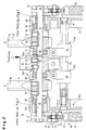
- the section shown on the right in FIG. 2 corresponds to the left section of FIG. 1.
- operating rod 41 a becomes a push rod 41b actuated, which in turn with a bushing or sleeve arranged on the shaft 15 66 interacts.
- the socket 66 is rotatably via grub screws 43, 44 with the shaft 15 connected.
- the inner end 38 of this rotated by the rod drive Shaft 15 is with a locking washer 45 in a groove against axial Moved secured.
- the section shown on the left in FIG. 2 corresponds to that shown on the right in FIG. 1 Area.
- the corresponding shaft 13 is at its inner end 37 two grub screws 46, 47 non-rotatably connected to the bush 65 of the connecting rod 12, which with the toothed plastic band 11, which with the front pedal part 4a or a projection 4c extending from this, in Active connection is established.
- the shaft 13 to be rotated in this way is also mounted by means of a bearing element 22 or a roller bearing 28. Between the two bearings 28, 35 holding the shaft 13 radially are the clamping head 16 with arranged upwardly extending mallet 2.
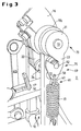
- the return spring 33 is at its end 48 facing the shaft 13 via a upper spring bearing element 75, which comprises a suspension element 69 for the spring, connected to a transmission element 70.
- the spring end 48 has an approximately semicircular ring 49 which is in a first transverse bore 50 of a connecting disc 51 is suspended.
- the connecting washer 51 has a second transverse bore 71, in which by means of a deep groove ball bearing 72 a bolt 52 is mounted, the bolt axis parallel to Wave axis runs.
- the suspension element 69 is made up of the connecting disk 51 and the bolt 52 together.
- the transmission element 70 is on Connecting rod 31, which is non-rotatably connected to the outer end 29 of the shaft 13.
- the Connecting rod 31 has two hooks 53, 54, into which suspension element 69 can be hung is.
- the return spring 33 is simple and quick Way out of the connecting rod 31.
- the lower end 55 of the return spring 33 (see FIG. 4) is pivotable lower spring bearing element 74 arranged on the column base 10c.
- the lower Bearing element 74 comprises an adjusting element 73 or adjusting element for the spring tension with a grub screw 56 and a receiving part 57 for the grub screw 56, which comprises a tab 60.
- This tab can be swiveled over a Rolling bearing 61, in particular a ball bearing, around a from the foot 10c of the bearing column 10 protruding rigid bolts 62 are arranged. Adjusting the spring tension takes place via two screw nuts 63, 64 on the threaded pin 56. Im A head 59 is made in the head of the threaded pin 56, into which a ring 58 is suspended on the lower part of the spring 33.
Landscapes
- Physics & Mathematics (AREA)
- Engineering & Computer Science (AREA)
- Acoustics & Sound (AREA)
- Multimedia (AREA)
- Electrophonic Musical Instruments (AREA)
- Road Paving Machines (AREA)
Abstract
Description
Die Erfindung betrifft eine Fußmaschine für Perkussions-Instrumente mit einem Lagersockel mit sich nach oben erstreckenden Säulen mit Lagern, in denen mindestens ein Schlegel mittels mindestens einer Welle verschwenkbar gehalten ist und entgegen der Kraft mindestens einer Rückstellfeder mittels eines durch ein Pedal bedienbaren Betätigungsmechanismusses bewegbar ist, mit jeweils einem mit einer Welle in Wirkverbindung stehenden Übertragungselement, das mit der Rückstellfeder verbunden ist.The invention relates to a pedal machine for percussion instruments with a Bearing base with columns extending upwards with bearings in which at least a mallet is held pivotably by means of at least one shaft and against the force of at least one return spring by means of a Pedal operated actuation mechanism is movable, each with one with a shaft operatively connected transmission element, which with the Return spring is connected.
Derartige Fußmaschinen dienen dazu, das Fußspiel eines Schlagzeugers schnell und präzise auf das Schlaginstrument, insbesondere eine Bass-Drum, zu übertragen. Hierbei wird die Fußmaschine üblicherweise mit einer Spannvorrichtung am Spannreifen der Bass-Drum befestigt. Eine solche Fußmaschine ist beispielsweise aus der DE 33 27 687 C2 bekannt. Diese weist einen Fuß mit hiervon hochragenden Ständern auf, die in ihren oberen Enden, beispielsweise über Wälzlager, eine horizontale Welle halten. Auf dieser Welle sitzen drehfest ein Kettenrad sowie ein Klemmkopf, in dem der Schlegel über das untere Ende eines Schaftes gehalten wird, wobei an dem oberen Ende des Schaftes das Schlagpolster befestigt ist. Das vordere Ende eines Pedals greift über einen Lagerbolzen an einem Ende einer Laschenkette an, die teilweise um das Kettenrad herumgelegt ist, und betätigt somit die Wellen- und folglich die Schlegelbewegung. Such pedals are used to quickly play a drummer's foot and transfer it precisely to the percussion instrument, especially a bass drum. Here, the foot machine is usually with a clamping device on Hoops attached to the bass drum. Such a foot pedal is for example known from DE 33 27 687 C2. This has a foot with towering of it Stands on, in their upper ends, for example via roller bearings, a keep horizontal wave. A sprocket and a non-rotating seat on this shaft Clamping head in which the mallet is held over the lower end of a shaft the impact pad is attached to the upper end of the shaft. The The front end of a pedal engages over a bearing pin at one end Link chain, which is partially wrapped around the sprocket, and thus actuates the wave and consequently the flail movement.
Eine solche Rückstellfederkonstruktion einer Fußmaschine für Schlaginstrumente ist ebenfalls aus der US 3,988,957 bekannt. Hierbei ist der untere Teil der Rückstellfeder mit einer Justierschraube verbunden, die ein Befestigungselement durchdringt, das jeweils am Fuß von zwei sich nach oben erstreckenden Rahmenteilen fest angeordnet ist.Such a return spring construction of a foot machine for percussion instruments is also known from US 3,988,957. Here is the lower part of the return spring connected with an adjusting screw which is a fastener penetrates, each at the foot of two upwardly extending frame parts is firmly arranged.
Die US 5,567,899 beschreibt eine Doppel-Fußmaschine mit zwei Wellen, die jeweils in Wirkverbindung mit einer Rückstellfeder stehen. Ein mit der Welle über eine Buchse verbundener Nocken ist mit einer Öffnung versehen, in der eine Rolle schwenkbar gelagert ist. Die Rolle ist mit einem Aufhängungsteil verlängert, an dem das obere Ende der Feder fest montiert ist. Das untere Ende der Feder ist mit einer Klammer am Säulenfuß verbunden und zwar über ein Einstellelement zur Einstellung der gewünschten Spannung der Rückstellfeder. Dieser Einstellelement umfaßt einen Gewindestift sowie ein Bauteil zur Verhinderung einer Rotation des Gewindestifts. Das untere Ende der Feder ist in eine Querbohrung des Gewindestiftkopfes schwingend eingehängt, während der Gewindestift rotationsfrei an der Klammer montiert ist.US 5,567,899 describes a double foot machine with two shafts, each are in operative connection with a return spring. One with the wave over a bushing of connected cams is provided with an opening in which a roller is pivotally mounted. The roll is extended with a suspension part the top of the spring is fixed. The lower end of the spring is with connected to a bracket on the column base and that via an adjusting element for Setting the desired tension of the return spring. This setting element comprises a threaded pin and a component for preventing rotation of the Threaded pin. The lower end of the spring is in a cross hole in the grub screw head swinging, while the grub screw rotates on the Bracket is mounted.
Bei derartigen Systemen bestimmt die Spannung der Rückstellfeder den Druck, den der Drummer mit seinem Fuß zum Verschwenken des Schlegels überwinden muß sowie die Geschwindigkeit, mit der das Pedal zurückschnellt.In such systems, the tension of the return spring determines the pressure that the drummer overcomes with his foot to pivot the drumstick and the speed at which the pedal flips back.
Ausgehend von einem solchen Stand der Technik liegt der Erfindung die Aufgabe zugrunde, eine Fußmaschine zu schaffen, die für den Drummer ein leichteres Spiel ermöglicht.Starting from such a prior art, the object of the invention to create a pedal machine that is easier for the drummer Game allows.
Diese Aufgabe wird durch die Fußmaschine mit den Merkmalen des Anspruchs 1
gelöst. Vorteilhafte Weiterentwicklungen sind in den Unteransprüchen beschrieben. This object is achieved by the foot machine with the features of
Grundgedanke der Erfindung ist, die Rückstellfeder mittels eines schwenkbaren unteren Federlagerelementes - unmittelbar - an dem unteren Säulenteil zu befestigen. Vorzugsweise umfaßt das schwenkbare untere Federlagerelement ein Einstellelement für die Einstellung der Rückstellfederspannung, das ebenfalls mitschwenkt. Das Einstellelement ist damit nicht rotationsfrei.The basic idea of the invention is the return spring by means of a pivotable lower spring bearing element - directly - to attach to the lower column part. The pivotable lower spring bearing element preferably comprises an adjusting element for setting the return spring tension, which also swivels. The setting element is therefore not rotation-free.
Aufgrund der schwingenden Lagerung wird das Spiel für den Drummer einfacher und angenehmer, weil ein geringerer Widerstand überwunden werden muß.Due to the swinging bearing, the game is easier for the drummer and more pleasant because less resistance has to be overcome.
Vorzugsweise umfaßt das Einstellelement ein Aufnahmeteil für einen Gewindestift, der mit der Rückstellfeder verbunden ist. Das Aufnahmeteil selbst weist eine Lasche auf, die mittels eines Lagers um einen zylinderförmigen Vorsprung, beispielsweise einen Bolzen, am unteren Säulenteil schwenkbar angeordnet ist.The adjusting element preferably comprises a receiving part for a threaded pin, which is connected to the return spring. The receiving part itself has a tab on by means of a bearing around a cylindrical projection, for example a bolt, is pivotally arranged on the lower part of the column.
Des weiteren wird vorgeschlagen, daß die Rückstellfeder an ihrem zur Welle hinweisenden Ende mittels eines oberen Federlagerelementes lösbar an dem Übertragungselement gelagert ist. Das obere Federlagerelement umfaßt ein Aufhängungselementes, in dem die Feder schwingend eingreift.Furthermore, it is proposed that the return spring on its pointing towards the shaft End detachably by means of an upper spring bearing element on the transmission element is stored. The upper spring bearing element comprises a suspension element, in which the spring engages swinging.
Nach einer bevorzugten Ausführungsform umfaßt das Aufhängungselement eine Verbindungsscheibe mit einem oberen und unteren Teil, wobei in den unteren Teil der Verbindungsscheibe eine erste Querbohrung eingebracht ist, in die das obere Ende der Rückstellfeder schwingend eingreift. In den oberen Teil der Verbindungsscheibe ist eine zweite Querbohrung mit einem Lager eingebracht ist, in dem ein Bolzen, dessen Achse parallel zur Wellenachse verläuft, angeordnet ist. Das Übertragungselement umfaßt ein mit einem Wellenende verbundenes Pleuel mit sich nach unten erstreckenden Haken, mit denen der Bolzen des Aufhängungselementes in Eingriff kommt. According to a preferred embodiment, the suspension element comprises a Connection disc with an upper and lower part, being in the lower part a first transverse bore is introduced into the connecting disk, into which the upper one Swinging end of the return spring engages. In the upper part of the connecting washer is a second cross hole with a bearing is introduced in a bolt, the axis of which is parallel to the shaft axis, is arranged. The transmission element comprises a connecting rod connected to a shaft end with downwardly extending hooks with which the bolt of the suspension element comes into engagement.
Auf diese Weise wird ein Aufhängungselement für die Feder bereitgestellt, das neben geringen Energieverlusten den Vorteil zeigt, daß es auf leichte Art und Weise von dem Pleuel trennbar ist, indem das Aufhängungsteil ausgehakt wird.In this way, a suspension element for the spring is provided, the in addition to low energy losses shows the advantage that it is easy and Can be separated from the connecting rod by unhooking the suspension part.
Zudem wird über die vorgeschlagene Federaufhängung und Lagerung erreicht, daß die Rückstellfeder trotz unterschiedlicher Position des verschwenkten Pleuels aufgrund einer Fußbetätigung und Verschwenken der Welle immer in einer im wesentlichen vertikalen Ausrichtung angeordnet bleibt und damit die Federkräfte besser ausgenutzt werden können.In addition, the proposed spring suspension and bearing that the return spring despite the different position of the pivoted connecting rod due to foot actuation and pivoting of the shaft always in one essentially remains vertically aligned and thus the spring forces can be better exploited.
Die vorgeschlagene schwenkbare Befestigung der Rückstellfeder kann bei allen Typen von Fußmaschinen zum Einsatz kommen.The proposed pivotable attachment of the return spring can be used in all Types of foot pedals are used.
Weitere Einzelheiten und Vorteile der Erfindung ergeben sich aus den Unteransprüchen und aus der nachfolgenden Beschreibung, in der die in den Figuren dargestellten Ausführungsformen der Erfindung näher erläutert werden. Dabei sind neben den oben aufgeführten Kombinationen von Merkmalen auch Merkmale alleine oder in anderen Kombinationen erfindungswesentlich. Es zeigen:
- Fig. 1
- eine Schrägansicht einer Fußmaschine für Perkussions-Musikinstrumente;
- Fig. 2
- eine Schnittansicht des oberen Bereichs der Fußmaschine nach Fig. 1 mit detaillierter Darstellung des Aufhängungselementes einer Rückstellfeder;
- Fig. 3
- eine seitliche Detailansicht der Fußmaschine nach Fig. 1 zur Darstellung des Aufhängungselementes der Rückstellfeder;
- Fig. 4
- eine seitliche Detailansicht der Fußmaschine nach Fig. 1 zur Verdeutlichung des Einstellelements der Rückstellfeder.
- Fig. 1
- an oblique view of a foot machine for percussion musical instruments;
- Fig. 2
- a sectional view of the upper portion of the foot machine of Figure 1 with a detailed view of the suspension element of a return spring.
- Fig. 3
- a detailed side view of the foot machine of Figure 1 showing the suspension element of the return spring.
- Fig. 4
- a detailed side view of the pedal machine according to FIG. 1 to illustrate the setting element of the return spring.
Bei der in Fig. 1 dargestellten Ausführungsform einer Fußmaschine für Perkussions-Musikinstrumente
handelt es sich um eine Fußmaschine 1 mit zwei Schlegeln
2, 3, die über ein zweigeteiltes Pedal 4 mit zwei unterschiedlichen Betätigungsmechanismen
5, 6 bedient werden. Der Lagersockel 7 der Fußmaschine 1 umfaßt
eine Bodenplatte 8, an der an ihrem zu der Bass-Drum D hinweisenden Ende 8a
zwei sich nach oben, von der Bodenplatte 8 rechtwinklig erstreckende Säulen 9,
10 lösbar mittels einer Schraub-Steckverbindung 68 montiert sind. Während der
Schlegel 2 über den vorderen Pedalteil 4a und über diesen mit einem Kunststoffband
11 zusammenwirkenden Pleuel 12, das über eine Buchse 65 (vgl. Fig. 2) auf
einer ersten Welle 13 angeordnet ist, bedient wird, wird der Schlegel 3 über den
hinteren Pedalteil 4b mittels eines Stangentriebs 14, der eine zweite Welle 15 in
eine Drehbewegung versetzt, bedient.In the embodiment of a foot machine for percussion musical instruments shown in FIG. 1
it is a
Neben dem gezeigten Stangentrieb und Riementrieb kommen als Betätigungsmechanismen für die Wellen- und damit die Schlegelbewegung alle anderen Arten ebenfalls in Frage, wie beispielsweise ein Kettentrieb. Bei dem Riementrieb kommt vorzugsweise als Zugmittel ein verstärktes Kunststoffband zu Anwendung; diese Verstärkung wird beispielsweise mittels eines integrierten Stahldrahtgewebes oder mittels eines integrierten zweiten Kunststoffes, wie Nylon, erreicht. Bei einem Kettentrieb empfiehlt sich insbesondere die Verwendung einer gezahnten Rollenkette, die über ein Kettenrad läuft. Zur Verhinderung eines störenden Geräuschs beim Ablaufen von Metall auf Metall ist das Kettenrad vorzugsweise gepolstert. Die Betätigungsmechanismen werden mittels jeweils eines separaten Pedals oder mittels eines zweigeteilten Pedals - wie hier gezeigt - bedient.In addition to the rod drive and belt drive shown come as actuation mechanisms for the wave and thus the flail movement of all other types also in question, such as a chain drive. With the belt drive a reinforced plastic tape is preferably used as a traction device; this reinforcement is achieved, for example, by means of an integrated steel wire mesh or by means of an integrated second plastic, such as nylon. at A chain drive is particularly recommended to use a toothed Roller chain that runs over a sprocket. To prevent annoying noise the sprocket is preferably padded when running from metal to metal. The actuation mechanisms are each using a separate pedal or operated using a two-part pedal - as shown here.
Auf beiden unabhängig arbeitenden Wellen 13, 15 der gezeigten Doppel-Fußmaschine
sind über drehfest mit den Wellen verbundenen Buchsen 67 und 66
(vgl. Fig. 2) Klemmköpfe 16, 17 angeordnet, in denen jeweils der Schlegel 2, 3
über das untere Ende eines Schaftes 18, 19 gehalten wird, wobei an dessen oberen
Ende das Schlagpolster 20, 21 angeordnet ist. On both independently working
Zur Lagerung der nicht durch die beiden Säulen 9 und 10 gehaltenen Enden der
beiden Wellen 13, 15 sind zwei Lagerelemente 22, 23 oder Stützböcke vorgesehen.
Diese sind über eine entsprechende Ausnehmung 24 (vgl. Fig. 3) an ihrem
einen Ende 22a, 23a mit einem Querträger 25 bzw. mit einer Traverse, hier in
Form einer Sechskantstange verbunden, der bzw. die parallel und vertikal beabstandet
unterhalb der Wellenlängsachse an den Säulen 9, 10 mittels Schraubverbindungen
40, 39 montiert ist und sich zwischen diesen erstreckt.For storing the ends of the not held by the two
Die beiden Lagerelemente 22, 23 nehmen an ihrem jeweils anderen Ende 26b,
26a Wälzlager 28, 27 für die Wellen 13 und 15 auf. Die äußeren Enden 29, 30
beider Wellen sind drehfest mit jeweils einem Pleuel 31, 32 verbunden, welches
jeweils in Wirkverbindung mit einer Rückstellfeder 33, 34 steht, die schwenkbar an
dem unteren Ende einer Säule 10, 9 befestigt ist.The two bearing
Die Grundelemente Bodenplatte 8 und Säulen 9, 10 bilden den Lagersockel 7.
Diese Säulen 9, 10 setzen sich im wesentlichen aus jeweils einer Strebe 9a, 10a
und einem Aufnahmeelement 9b, 10b für ein Wälzlager 36, 35, hier Kugellager
zusammen, um die äußeren Wellenenden 30, 29 zu halten. Um ein Gegenlager
für die jeweils anderen bzw. hier inneren Wellenenden 38, 37 zu schaffen, sind die
beiden zusätzlichen Wälzlager 27, 28 vorgesehen. Diese sind Bestandteil der beiden
Lagerelemente 23, 22, die an dem Querträger 25 bzw. der Sechskantstange
befestigt sind.The basic
Der in Fig. 2 rechts dargestellte Abschnitt entspricht dem linken Abschnitt der Fig.
1. Mittels einer sich in Richtung der Säulen 9, 10 und in etwa parallel zu der Bodenplatte
8 erstreckenden Betätigungsstange 41 a wird eine Schubstange 41b
betätigt, die wiederum mit einer an der Welle 15 angeordneten Buchse bzw. Hülse
66 zusammenwirkt. Die Buchse 66 ist drehfest über Madenschrauben 43, 44 mit
der Welle 15 verbunden. Das innere Ende 38 dieser durch den Stangentrieb gedrehten
Welle 15 ist mit einer Sicherungsscheibe 45 in einer Nut gegen axiales
Verschieben gesichert.The section shown on the right in FIG. 2 corresponds to the left section of FIG.
1. By means of one in the direction of the
Der in Fig. 2 links dargestellte Abschnitt entspricht dem in Fig. 1 rechts dargestellten
Bereich. Die entsprechende Welle 13 ist an ihrem inneren Ende 37 über
zwei Madenschrauben 46, 47 drehfest mit der Buchse 65 des Pleuels 12 verbunden,
welches mit dem gezahnten Kunststoffband 11, das mit dem vorderen Pedalteil
4a bzw. einem von diesem ausgehenden Vorsprung 4c zusammenwirkt, in
Wirkverbindung steht. Die auf diese Weise zu drehende Welle 13 ist ebenfalls
mittels eines Lagerelementes 22 bzw. eines Wälzlagers 28 gelagert. Zwischen
den beiden, die Welle 13 radial haltenden, Lagern 28, 35 ist der Klemmkopf 16 mit
sich nach oben erstreckendem Schlegel 2 angeordnet.The section shown on the left in FIG. 2 corresponds to that shown on the right in FIG. 1
Area. The corresponding
Aus Fig. 2 wird deutlich, daß es sich um zwei Wellen 13, 15 handelt, die in dem
mit dem Pfeil gekennzeichneten Schnitt getrennt sind. Es wird deutlich, daß es
durch die vorgeschlagene Konstruktion mit Hilfe des Querträgers 25 sowie der
Lagerelemente 22, 23 bzw. entsprechenden Anzahl an Zwischenlagern möglich
wird, die Fußmaschine mit einer oder zwei oder ggf. mehreren Wellen mit entsprechenden
Betätigungsmechanismen auszurüsten.From Fig. 2 it is clear that there are two
Die Aufhängung bzw. die Lagerung der jeweiligen Rückstellfedern 33, 34 wird mit
Hilfe der Fig. 2, 3 und 4 deutlich. Die Fig. 3 und 4 zeigen jeweils die Ansicht auf
die Welle 13, deren Rückstellfedersystem hier nun im einzelnen beschrieben wird.
Die Lagerung der Rückstellfeder 34 der durch den Stangentrieb bedienten Welle
15 ist analog.The suspension or the storage of the respective return springs 33, 34 is with
2, 3 and 4 clearly. 3 and 4 each show the view
the
Die Rückstellfeder 33 ist an ihrem zu der Welle 13 hinweisenden Ende 48 über ein
oberes Federlagerelement 75, das ein Aufhängungselement 69 für die Feder umfaßt,
mit einem Übertragungselement 70 verbunden. The
Das Federende 48 weist einen in etwa halbkreisförmigen Ring 49 auf, der in eine
erste Querbohrung 50 einer Verbindungsscheibe 51 eingehängt ist. Die Verbindungsscheibe
51 weist eine zweite Querbohrung 71 auf, in der mittels eines Rillenkugellagers
72 ein Bolzen 52 gelagert ist, dessen Bolzenachse parallel zur
Wellenachse verläuft. Das Aufhängungselement 69 setzt sich aus der Verbindungsscheibe
51 und dem Bolzen 52 zusammen.The
Nach dem gezeigten Ausführungsbeispiel ist das Übertragungselement 70 ein
Pleuel 31, das drehfest mit dem äußeren Ende 29 der Welle 13 verbunden ist. Das
Pleuel 31 weist zwei Haken 53, 54 auf, in die das Aufhängungselement 69 einhängbar
ist. Auf diese Weise ist die Rückstellfeder 33 auf einfache und schnelle
Weise aus dem Pleuel 31 aus - bzw. einzuhängen.According to the exemplary embodiment shown, the
Das untere Ende 55 der Rückstellfeder 33 (vgl. Fig. 4) ist mit einem schwenkbaren
unteren Federlagerelement 74 an dem Säulenfuß 10c angeordnet. Das untere
Lagerelement 74 umfaßt ein Einstellelement 73 bzw. Justierelement für die Federspannung
mit einem Gewindestift 56 sowie einem Aufnahmeteil 57 für den Gewindestift
56, der eine Lasche 60 umfaßt. Diese Lasche ist schwenkbar über ein
Wälzlager 61, insbesondere ein Kugellager, um einen aus dem Fuß 10c der Lagersäule
10 vorstehenden starren Bolzen 62 angeordnet. Die Justierung der Federspannung
erfolgt über zwei Schraubmuttern 63, 64 an dem Gewindestift 56. Im
Kopf des Gewindestiftes 56 ist eine Bohrung 59 eingebracht, in den ein Ring 58
am unteren Teil der Feder 33 eingehängt ist.The
Claims (8)
mit einem Lagersockel (7) mit sich nach oben erstreckenden Säulen (9, 10) mit Lagern (36, 35), in denen mindestens ein Schlegel (3, 2) mittels mindestens einer Welle (15, 13) verschwenkbar gehalten ist und entgegen der Kraft mindestens einer Rückstellfeder (34, 33) mittels eines durch ein Pedal (4) bedienbaren Betätigungsmechanismusses (5, 6) bewegbar ist,
mit jeweils einem mit einer Welle (15, 13) in Wirkverbindung stehenden Übertragungselement (70), das mit der Rückstellfeder (33, 34) verbunden ist,
dadurch gekennzeichnet, daß die Rückstellfeder (33) mittels eines schwenkbaren unteren Federlagerelementes (74) an einem unteren Säulenteil befestigt ist.Pedal (1) for percussion instruments
with a bearing base (7) with upwardly extending columns (9, 10) with bearings (36, 35) in which at least one beater (3, 2) is held pivotably by means of at least one shaft (15, 13) and against the Force of at least one return spring (34, 33) can be moved by means of an actuating mechanism (5, 6) that can be operated by a pedal (4),
each with a transmission element (70) which is operatively connected to a shaft (15, 13) and which is connected to the return spring (33, 34),
characterized in that the return spring (33) is fastened to a lower column part by means of a pivotable lower spring bearing element (74).
dadurch gekennzeichnet, daß das schwenkbare untere Federlagerelement (74) ein Einstellelement (73) für die Einstellung der Rückstellfederspannung umfaßt. Pedal machine according to claim 1,
characterized in that the pivotable lower spring bearing element (74) comprises an adjusting element (73) for adjusting the return spring tension.
dadurch gekennzeichnet, daß das Einstellelement (73) ein Aufnahmeteil (57) für einen Gewindestift (56) umfaßt, der mit der Rückstellfeder (33, 34) verbunden ist, und
das Aufnahmeteil (57) eine Lasche (60) aufweist, die mittels eines Lagers (61) um einen zylinderförmigen Vorsprung am unteren Säulenteil schwenkbar angeordnet ist.Pedal machine according to claim 1 or 2,
characterized in that the adjusting element (73) comprises a receiving part (57) for a threaded pin (56) which is connected to the return spring (33, 34), and
the receiving part (57) has a tab (60) which is arranged by means of a bearing (61) so as to be pivotable about a cylindrical projection on the lower column part.
dadurch gekennzeichnet, daß die Rückstellfeder (33, 34) an ihrem zur Welle hinweisenden Ende (48) mittels eines oberen Federlagerelementes (75) lösbar an dem Übertragungselement (70) gelagert ist.Pedal machine according to one of claims 1 to 3,
characterized in that the return spring (33, 34) is detachably mounted on the transmission element (70) at its end (48) pointing towards the shaft by means of an upper spring bearing element (75).
dadurch gekennzeichnet, daß das obere Federlagerelement (75) ein Aufhängungselement (69) umfaßt, an dem die Rückstellfeder (33, 34) schwingend aufgehängt ist.Pedal machine according to claim 4,
characterized in that the upper spring bearing element (75) comprises a suspension element (69) on which the return spring (33, 34) is suspended in a swinging manner.
dadurch gekennzeichnet, daß das Aufhängungselement (69) eine Verbindungsscheibe (51) mit einem oberen und unteren Teil umfaßt und
daß in den unteren Teil eine erste Querbohrung (50) eingebracht ist, in die das obere Ende (48) der Rückstellfeder (33) schwingend eingreift, und
daß in den oberen Teil eine zweite Querbohrung (71) mit einem Lager (72) eingebracht ist, in dem ein Bolzen (52), dessen Achse parallel zur Wellenachse verläuft, angeordnet ist. Pedal machine according to claim 5,
characterized in that the suspension element (69) comprises a connecting disc (51) with an upper and lower part and
that in the lower part a first transverse bore (50) is made, in which the upper end (48) of the return spring (33) engages in a swinging manner, and
that in the upper part a second transverse bore (71) is made with a bearing (72) in which a bolt (52), the axis of which is parallel to the shaft axis, is arranged.
dadurch gekennzeichnet, daß das Übertragungselement (70) ein mit einem Wellenende (29) verbundenes Pleuel (31) mit sich nach unten erstreckenden Haken (53, 54) umfaßt, mit denen der Bolzen (52) des Aufhängungselementes (69) in Eingriff kommt.Pedal machine according to claim 6,
characterized in that the transmission element (70) comprises a connecting rod (31) connected to a shaft end (29) with downwardly extending hooks (53, 54) with which the bolt (52) of the suspension element (69) comes into engagement.
dadurch gekennzeichnet, daß das Aufnahmeteil (57) mittels Schraubmuttern (63, 64) gegenüber dem Gewindestift (56) justierbar ist
und daß das untere Ende (55) der Rückstellfeder (33) in einer Bohrung (59) im Kopf des Gewindestiftes (56) eingehängt ist.Pedal machine according to one of claims 3 to 7,
characterized in that the receiving part (57) is adjustable relative to the threaded pin (56) by means of screw nuts (63, 64)
and that the lower end (55) of the return spring (33) is suspended in a bore (59) in the head of the threaded pin (56).
Applications Claiming Priority (2)
| Application Number | Priority Date | Filing Date | Title |
|---|---|---|---|
| DE10109942A DE10109942A1 (en) | 2001-03-01 | 2001-03-01 | Pedal for percussion instruments |
| DE10109942 | 2001-03-01 |
Publications (2)
| Publication Number | Publication Date |
|---|---|
| EP1237147A1 true EP1237147A1 (en) | 2002-09-04 |
| EP1237147B1 EP1237147B1 (en) | 2006-11-15 |
Family
ID=7675976
Family Applications (1)
| Application Number | Title | Priority Date | Filing Date |
|---|---|---|---|
| EP02004449A Expired - Lifetime EP1237147B1 (en) | 2001-03-01 | 2002-02-27 | Pedal device for a bass-drum |
Country Status (2)
| Country | Link |
|---|---|
| EP (1) | EP1237147B1 (en) |
| DE (2) | DE10109942A1 (en) |
Cited By (1)
| Publication number | Priority date | Publication date | Assignee | Title |
|---|---|---|---|---|
| US8410346B2 (en) | 2010-09-29 | 2013-04-02 | Sonor Gmbh & Co. Kg | Bass-drum pedal assembly |
Citations (3)
| Publication number | Priority date | Publication date | Assignee | Title |
|---|---|---|---|---|
| DE352883C (en) * | 1921-03-12 | 1922-05-09 | William Fredrich Ludwig | Percussion for drum and cymbal |
| US5726370A (en) * | 1995-12-29 | 1998-03-10 | Pearl Musical Instrument Co. | Hoop clamping system for a bass drum pedal assembly |
| US6137040A (en) * | 1998-01-21 | 2000-10-24 | Hoshino Gakki Co., Ltd. | Spring structure for a drum pedal |
-
2001
- 2001-03-01 DE DE10109942A patent/DE10109942A1/en not_active Withdrawn
-
2002
- 2002-02-27 EP EP02004449A patent/EP1237147B1/en not_active Expired - Lifetime
- 2002-02-27 DE DE50208673T patent/DE50208673D1/en not_active Expired - Fee Related
Patent Citations (3)
| Publication number | Priority date | Publication date | Assignee | Title |
|---|---|---|---|---|
| DE352883C (en) * | 1921-03-12 | 1922-05-09 | William Fredrich Ludwig | Percussion for drum and cymbal |
| US5726370A (en) * | 1995-12-29 | 1998-03-10 | Pearl Musical Instrument Co. | Hoop clamping system for a bass drum pedal assembly |
| US6137040A (en) * | 1998-01-21 | 2000-10-24 | Hoshino Gakki Co., Ltd. | Spring structure for a drum pedal |
Cited By (1)
| Publication number | Priority date | Publication date | Assignee | Title |
|---|---|---|---|---|
| US8410346B2 (en) | 2010-09-29 | 2013-04-02 | Sonor Gmbh & Co. Kg | Bass-drum pedal assembly |
Also Published As
| Publication number | Publication date |
|---|---|
| EP1237147B1 (en) | 2006-11-15 |
| DE50208673D1 (en) | 2006-12-28 |
| DE10109942A1 (en) | 2002-09-19 |
Similar Documents
| Publication | Publication Date | Title |
|---|---|---|
| EP1237145B1 (en) | Pedal device for a bass-drum | |
| DE3521794C2 (en) | ||
| DE69725418T2 (en) | Rear gear shift for bicycle | |
| EP0350748B1 (en) | Actuating device for a spring mechanism in an adjustable chair | |
| DE69633749T2 (en) | Modular disc brake and operating lever for this | |
| DE69308783T2 (en) | Fastening device for wheels, in particular for roller skates | |
| DE3819179C2 (en) | ||
| DE19720375B4 (en) | Drum beater | |
| DE3537203A1 (en) | Work chair with inclination mechanism for seat and back | |
| CH690019A5 (en) | Supporting frame for a chair, in particular for an adjustable in height and tilt office chair. | |
| EP0485868A1 (en) | Chair, in particular office chair | |
| DE102018106119A1 (en) | Bicycle component actuating device | |
| DE3802560A1 (en) | FRONT DERAILLEUR FOR A BICYCLE | |
| EP0700487A1 (en) | Disc brake, especially for vehicles | |
| DE3621043C2 (en) | ||
| DE3621042C2 (en) | ||
| DE3318949C2 (en) | ||
| DE10000879B4 (en) | Tree stand, in particular Christmas tree stand | |
| DE2462892C2 (en) | Automatic adjustment device for vehicle outer band brakes | |
| EP1358783A1 (en) | Spring-loaded tool holding arrangement and adjustable pivoting device therefor | |
| EP1237147B1 (en) | Pedal device for a bass-drum | |
| DE3819346A1 (en) | Brake spring coupling for adjustment gears, in particular of seat adjustment devices, preferably in motor vehicles | |
| DE2108441B2 (en) | Drawing table | |
| DE102008006242A1 (en) | Scooter or skateboard, has spring element pressurizing pivotably supported front wheels in center position, where spring element is arranged co-axial to connecting rod that is movably arranged at support element | |
| DE1206748B (en) | Change transmission with chain switching for bicycles or the like. |
Legal Events
| Date | Code | Title | Description |
|---|---|---|---|
| PUAI | Public reference made under article 153(3) epc to a published international application that has entered the european phase |
Free format text: ORIGINAL CODE: 0009012 |
|
| AK | Designated contracting states |
Kind code of ref document: A1 Designated state(s): AT BE CH CY DE DK ES FI FR GB GR IE IT LI LU MC NL PT SE TR |
|
| AX | Request for extension of the european patent |
Free format text: AL;LT;LV;MK;RO;SI |
|
| 17P | Request for examination filed |
Effective date: 20030220 |
|
| AKX | Designation fees paid |
Designated state(s): DE FR GB IT |
|
| 17Q | First examination report despatched |
Effective date: 20050506 |
|
| GRAP | Despatch of communication of intention to grant a patent |
Free format text: ORIGINAL CODE: EPIDOSNIGR1 |
|
| GRAS | Grant fee paid |
Free format text: ORIGINAL CODE: EPIDOSNIGR3 |
|
| GRAA | (expected) grant |
Free format text: ORIGINAL CODE: 0009210 |
|
| AK | Designated contracting states |
Kind code of ref document: B1 Designated state(s): DE FR GB IT |
|
| PG25 | Lapsed in a contracting state [announced via postgrant information from national office to epo] |
Ref country code: IT Free format text: LAPSE BECAUSE OF FAILURE TO SUBMIT A TRANSLATION OF THE DESCRIPTION OR TO PAY THE FEE WITHIN THE PRESCRIBED TIME-LIMIT;WARNING: LAPSES OF ITALIAN PATENTS WITH EFFECTIVE DATE BEFORE 2007 MAY HAVE OCCURRED AT ANY TIME BEFORE 2007. THE CORRECT EFFECTIVE DATE MAY BE DIFFERENT FROM THE ONE RECORDED. Effective date: 20061115 |
|
| REG | Reference to a national code |
Ref country code: GB Ref legal event code: FG4D Free format text: NOT ENGLISH |
|
| REF | Corresponds to: |
Ref document number: 50208673 Country of ref document: DE Date of ref document: 20061228 Kind code of ref document: P |
|
| GBV | Gb: ep patent (uk) treated as always having been void in accordance with gb section 77(7)/1977 [no translation filed] |
Effective date: 20061115 |
|
| EN | Fr: translation not filed | ||
| EN | Fr: translation not filed | ||
| PLBE | No opposition filed within time limit |
Free format text: ORIGINAL CODE: 0009261 |
|
| STAA | Information on the status of an ep patent application or granted ep patent |
Free format text: STATUS: NO OPPOSITION FILED WITHIN TIME LIMIT |
|
| 26N | No opposition filed |
Effective date: 20070817 |
|
| PG25 | Lapsed in a contracting state [announced via postgrant information from national office to epo] |
Ref country code: GB Free format text: LAPSE BECAUSE OF FAILURE TO SUBMIT A TRANSLATION OF THE DESCRIPTION OR TO PAY THE FEE WITHIN THE PRESCRIBED TIME-LIMIT Effective date: 20061115 |
|
| PG25 | Lapsed in a contracting state [announced via postgrant information from national office to epo] |
Ref country code: FR Free format text: LAPSE BECAUSE OF FAILURE TO SUBMIT A TRANSLATION OF THE DESCRIPTION OR TO PAY THE FEE WITHIN THE PRESCRIBED TIME-LIMIT Effective date: 20070629 |
|
| PG25 | Lapsed in a contracting state [announced via postgrant information from national office to epo] |
Ref country code: FR Free format text: LAPSE BECAUSE OF FAILURE TO SUBMIT A TRANSLATION OF THE DESCRIPTION OR TO PAY THE FEE WITHIN THE PRESCRIBED TIME-LIMIT Effective date: 20061115 |
|
| PGFP | Annual fee paid to national office [announced via postgrant information from national office to epo] |
Ref country code: DE Payment date: 20090219 Year of fee payment: 8 |
|
| PG25 | Lapsed in a contracting state [announced via postgrant information from national office to epo] |
Ref country code: DE Free format text: LAPSE BECAUSE OF NON-PAYMENT OF DUE FEES Effective date: 20100901 |