EP1211798B1 - Methode und Vorrichtung zur Motorsteuerung - Google Patents
Methode und Vorrichtung zur Motorsteuerung Download PDFInfo
- Publication number
- EP1211798B1 EP1211798B1 EP01126007.2A EP01126007A EP1211798B1 EP 1211798 B1 EP1211798 B1 EP 1211798B1 EP 01126007 A EP01126007 A EP 01126007A EP 1211798 B1 EP1211798 B1 EP 1211798B1
- Authority
- EP
- European Patent Office
- Prior art keywords
- current
- command value
- motor
- higher harmonics
- current command
- Prior art date
- Legal status (The legal status is an assumption and is not a legal conclusion. Google has not performed a legal analysis and makes no representation as to the accuracy of the status listed.)
- Expired - Lifetime
Links
Images

Classifications
-
- H—ELECTRICITY
- H02—GENERATION; CONVERSION OR DISTRIBUTION OF ELECTRIC POWER
- H02P—CONTROL OR REGULATION OF ELECTRIC MOTORS, ELECTRIC GENERATORS OR DYNAMO-ELECTRIC CONVERTERS; CONTROLLING TRANSFORMERS, REACTORS OR CHOKE COILS
- H02P6/00—Arrangements for controlling synchronous motors or other dynamo-electric motors using electronic commutation dependent on the rotor position; Electronic commutators therefor
- H02P6/10—Arrangements for controlling torque ripple, e.g. providing reduced torque ripple
-
- H—ELECTRICITY
- H02—GENERATION; CONVERSION OR DISTRIBUTION OF ELECTRIC POWER
- H02P—CONTROL OR REGULATION OF ELECTRIC MOTORS, ELECTRIC GENERATORS OR DYNAMO-ELECTRIC CONVERTERS; CONTROLLING TRANSFORMERS, REACTORS OR CHOKE COILS
- H02P21/00—Arrangements or methods for the control of electric machines by vector control, e.g. by control of field orientation
- H02P21/02—Arrangements or methods for the control of electric machines by vector control, e.g. by control of field orientation specially adapted for optimising the efficiency at low load
-
- H—ELECTRICITY
- H02—GENERATION; CONVERSION OR DISTRIBUTION OF ELECTRIC POWER
- H02P—CONTROL OR REGULATION OF ELECTRIC MOTORS, ELECTRIC GENERATORS OR DYNAMO-ELECTRIC CONVERTERS; CONTROLLING TRANSFORMERS, REACTORS OR CHOKE COILS
- H02P21/00—Arrangements or methods for the control of electric machines by vector control, e.g. by control of field orientation
- H02P21/06—Rotor flux based control involving the use of rotor position or rotor speed sensors
Definitions
- the present invention relates to an apparatus and a method adopted to control the drive of an AC motor.
- a current control circuit that controls the current in a three-phase alternating current motor normally performs the control arithmetic operation by converting a three-phase alternating current to a direct current in order to facilitate the arithmetic operation (see Japanese Laid-Open Patent Publication No. H 08-331885 ).
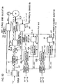
- FIG. 33 shows the structure adopted in a three-phase alternating current motor control apparatus which constitutes the related art.
- a rotating orthogonal coordinate system (dq -coordinate system) is used.
- the direction of the exciting current component in the current flowing through the three-phase alternating current motor is set along the d-axis and the direction of the torque current component in the current flowing through the three-phase alternating current motor is set along the q-axis perpendicular to the d-axis.
- the current control arithmetic operation is performed using a direct current value obtained by converting the three-phase alternating current value in the rotating orthogonal coordinate system to reduce the current control deviation.
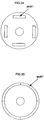
- Miniaturization and higher efficiency are achieved with regard to an AC motor by providing a rotor having internally embedded magnets, as shown in FIG. 34 and a stator assuming a concentrated windings structure.
- the rotor is able to effectively utilize the magnetic torque and the reluctance torque.
- a motor having this type of rotor is called an IPM (interior permanent magnet motor).
- the stator is capable of greatly reducing the coil end.
- a motor provided with the rotor and the stator having structures described above, which is called a concentrated winding IPM motor, has been attracting a great deal of interest as a motor capable of realizing miniaturization and a high degree of efficiency.
- EP 0 982 844 A1 discloses to control a motor current as output of a three-phase AC calculating section based on a torque control value as output of a torque control section and an output of a third harmonic generation section.
- the torque control section, the third harmonic generation section and the three-phase AC calculating section respectively correspond to the fundamental current command value determining means, the higher harmonics current command value determining means and the a current control means according to the preamble part of claim 1.
- FIG. 35 shows an SPM motor assuming a surface magnet structure achieved by covering the surface of the rotor with magnets. Unlike in the SPM motor shown in FIG. 35 ; areas where magnets are embedded and areas where no magnet is embedded are present along the circumference of the rotor in the IPM motor with the internally embedded magnets shown in FIG. 34 . Accordingly, while a uniform magnetic flux distribution is achieved in the SPM motor having a rotor, the surface of which is covered with magnets, a greater degree of change in the magnetic flux manifests in the IPM motor to result in a greater space harmonics component.
- An object of the present invention is to provide a motor control apparatus and a motor control method that improve control performance in a motor with significant space harmonics.
- the motor control apparatus comprises a fundamental current command value determining means for determining a fundamental current command value for a motor current, a higher harmonics current command value determining means for determining a higher harmonics current command value for the motor current and a current control means for controlling the current flowing to the AC motor based upon the fundamental current command value and the higher harmonics current command value.
- a fundamental current command value for a motor current is determined, a higher harmonics current command value for the motor current is determined and the current flowing to the AC motor is controlled based upon the fundamental current command value and higher harmonics current command value.
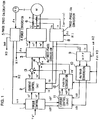
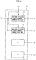
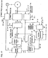
- FIG. 1 shows the structure of the motor control apparatus in the first embodiment.
- the motor control apparatus in the first embodiment implements vector control on a three-phase alternating current motor to realize torque control equivalent to the control achieved on a DC motor.
- the motor control apparatus in the first embodiment is provided with a fundamental current control circuit and a higher harmonics current control circuit.
- the fundamental current control circuit implements control on the fundamental wave components of motor currents iu, iv and iw by using a dq coordinate system.
- the dq coordinate system which is constituted with a d-axis corresponding to the exciting current components of the three-phase currents iu, iv and iw flowing to a three-phase alternating current motor M and a q-axis corresponding to the torque current components of the currents iu, iv and iw, rotates in synchronization with the motor rotation.
- the higher harmonics current control circuit controls the higher harmonics components contained in the motor currents iu, iv and iw by using a higher harmonics coordinate system.
- the higher harmonics coordinate system is an orthogonal coordinate system that rotates with the frequency of a higher harmonics component of a specific order manifesting when the motor currents iu, iv and iw are controlled by engaging the fundamental current control circuit alone, and it rotates with a frequency which is an integral multiple of the frequency of fundamental wave components of the motor currents iu, iv and iw.
- the fundamental current control circuit includes a torque control unit 1, a fundamental current control unit 2, a dq / three-phase conversion unit 3, a power conversion unit 4, a phase speed calculation unit 5 and a three-phase / dq conversion unit 8. It is to be noted that the structure of the fundamental current control circuit is identical to the structure adopted in the motor control apparatus in the related art illustrated in FIG. 33 .
- the torque control unit 1 calculates a d-axis current command value id* and a q-axis current command value iq* in the dq coordinate system and also calculates dh-axis current command values idh* and a qh-axis current command value iqh* in the higher harmonics coordinate system dhqh by using current command value tables, based upon the torque command value Te* and a motor rotating speed we, as detailed later in reference to FIG. 5 .
- the resulting current command values id* and iq* are provided to the fundamental current control unit 2, whereas the current command values idh* and iqh* that have been calculated are provided to a higher harmonics current control unit 11.
- the fundamental current control unit (dq-axis current control unit) 2 calculates fundamental wave voltage command values vd* and vq* corresponding to the d-axis and the q-axis in order to match the actual currents id and iq along the d-axis and the q-axis respectively with the current command values id* and iq* .
- the dq / three-phase conversion unit 3 converts voltage command values (vd* + vd' and vq* + vq') along the d-axis and the q-axis to three-phase alternating current voltage command values vu*, vv* and vw* based upon the phase ⁇ e of dq coordinate system viewed from the three-phase AC coordinate system.
- the voltage command values (vd* + vd') and (vq* + vq') corresponding to the d-axis and the q-axis are to be detailed later.
- the three-phase AC voltage command values vu*, vv* and vw* resulting from the conversion are provided to the power conversion unit 4.
- the power conversion unit 4 employs a power conversion element such as an IGBT to switch the DC voltage from a DC source (not shown) which may be a battery based upon the three-phase AC voltage command values vu*, vv* and vw* and applies three-phase AC voltages U, V and W to the three-phase alternating current motor M.
- a DC source not shown
- An encoder PS linked to the three-phase alternating current motor M detects the rotating position ⁇ m of the motor M. The rotating position ⁇ m thus detected is provided to the phase speed calculation unit 5.
- the phase speed calculation unit 5 calculates the rotating speed we of the motor M and the phase ⁇ e of the dq coordinate system viewed from the three-phase AC coordinate system based upon the rotating position signal ⁇ m provided by the encoder PS.
- Current sensors 6 and 7 respectively detect the actual currents iu and iv at the U-phase and the V-phase in the three-phase alternating current motor M.
- the detected U-phase current iu and V-phase current iv are provided to the three-phase / dq conversion unit 8.
- the higher harmonics current control circuit includes the three-phase / dq conversion unit 8, a high pass filter 9, a dq / dhqh conversion unit 10, the higher harmonics current control unit 11 and a dhqh /dq conversion unit 12.
- the high pass filter 9 extracts higher harmonics components id_h and iq_h by filtering the actual current id along the d-axis and the actual current iq along the q-axis based upon the motor rotating speed we.
- the dq / dhqh conversion unit 10 which has the higher harmonics coordinate system dhqh mentioned earlier, converts the higher harmonics components id_h of the actual current id along the d-axis and iq_h of the actual current iq along the q-axis to actual currents idh and iqh in the higher harmonics coordinate system dhqh.
- ⁇ eh represents the phase of the dhqh coordinate system viewed from the dq coordinate system
- the actual currents idh and iqh in the dhqh coordinate system are calculated through the following expression (1).
- idh iqh cos ⁇ eh sin ⁇ eh ⁇ sin ⁇ eh cos ⁇ eh id _ h iq _ h
- the higher harmonics current control unit(dhqh axis current control unit) 11 calculates higher harmonics voltage command values vdh* and vqh* respectively corresponding to the dh-axis and the qh-axis so as to match the actual currents idh and iqh along the dh-axis and the qh-axis with current command values idh* and iqh*.
- the dhqh / dq conversion unit 12 converts the higher harmonics voltage command values vdh* and vqh* along the dh-axis and the qh-axis to higher harmonics voltage command values vd' and vq' along the d-axis and the q-axis respectively.
- This conversion may be achieved by reversing conversion in expression (1).
- the voltage command values vd' and vq' resulting from the conversion are provided to adders 13 and 14.
- the adders 13 and 14 obtain the ultimate d-axis voltage command value (vd* + vd') and q-axis voltage command value (vq* + vq') by adding the higher harmonics voltage command values vd' and vq' generated at the higher harmonics current control circuit to the fundamental voltage command values vd* and vq* generated at the fundamental current control unit 2.
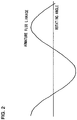
- FIG. 2 shows the armature flux linkage (U-phase winding) formed by the magnets in the IPM motor when there is no space harmonic present.
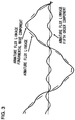
- FIG. 3 shows the armature flux linkage (U-phase winding) formed by the magnets in the IPM motor when there are fifth order space harmonic components.
- the magnetic flux changes by achieving the shape of a sine wave relative to the change in the rotating angle of the motor.
- the direction of the armature flux linkage vector is represented by the d-axis and the direction perpendicular to the d-axis is represented by the q-axis.
- physical quantities such as the voltages, the currents or the like in the three-phase AC coordinate system are converted to physical quantities in the dq coordinate system (fundamental coordinate system) and motor control is implemented in the dq coordinate system.
- the fundamental wave components in the physical quantities such as voltages or currents are handled in the dq coordinate system whereas the higher harmonics components are handled in the dhqh coordinate system (higher harmonics coordinate system) by assuming the direction of the armature flux linkage vector along the dh-axis and assuming the direction perpendicular to the dh-axis along the qh-axis for each order.
- the armature flux linkage is divided into a fundamental wave component magnetic flux and a fifth-order higher harmonics component magnetic flux, with the direction of the armature flux linkage vector of the fundamental wave component assumed along the d-axis and with the direction perpendicular to the d-axis assumed along the q-axis, and the direction of the armature flux linkage vector of the fifth-order higher harmonics component assumed along the dh-axis and the direction perpendicular to the dh-axis assumed along the qh-axis.
- the fundamental coordinate system dq constitutes a coordinate system that rotates in synchronization with the fundamental wave component of the armature flux linkage and the higher harmonics coordinate system dhqh constitutes a coordinate system that rotates in synchronization with the higher order harmonics component of the armature flux linkage.
- the higher harmonics component is allowed to conform to the current with higher accuracy.
- a higher harmonics current contains higher harmonics components of a plurality of orders. For purposes of achieving simplification, it is assumed in the following explanation that a kth-order higher harmonics component, which manifests a greater degree of influence among the higher harmonics components contained in the higher harmonics current represents the control target.
- id represents the d-axis current
- id_1 represents the fundamental wave component of the d-axis current
- id_h represents the higher harmonics component of the d-axis current
- iq represents the q-axis current
- iq_1 represents the fundamental wave component of the q-axis current
- iq_h represents the higher harmonics component of the q-axis current.
- id_1 representing the fundamental wave component of the d-axis current id
- id_h representing the higher harmonics component of the d-axis current id in the fundamental coordinate system dq
- the fundamental currents id_i and iq_i and the higher harmonics currents id_h and iq_h are handled in the fundamental coordinate system dq and ultimately, the d-axis higher harmonics current id_h and the q-axis higher harmonics current iq_h are converted to the dh-axis higher harmonics current idh and the qh-axis higher harmonics current iqh to facilitate understanding thereof.
- the first term in the right member in expression (3) represents the torque generated based upon the motor armature flux linkage fundamental wave components and the current fundamental wave components.
- the second term represents the torque generated based upon the motor armature flux linkage higher harmonics components and the current higher harmonics components.
- the third term represents the torque generated based upon the motor armature flux linkage higher harmonics components and the current fundamental wave components.
- the fourth term represents the torque generated based upon the motor armature flux linkage fundamental wave components of and the current higher harmonics components.
- the torques expressed in the third term and the fourth term in the right member in expression (3) each contain the product of an armature flux linkage component and a current component, the order of which is different from that of the armature flux linkage component, their time averages are both 0. Accordingly, the torques expressed in the third term and the fourth term do not constitute a contributing factor in the average torque output from the motor.
- the torque expressed in the first term is constituted of the product of the fundamental wave components of the armature flux linkage and the fundamental wave components of the corresponding currents, and thus, it constitutes a contributing factor in the average torque.
- the torque expressed in the second term, too which contains the products of the higher harmonics components of an armature flux linkage and the higher harmonics components of the corresponding currents of the same order, constitutes a contributing factor in the average torque.
- the motor control apparatus in the related art implements fundamental wave current control in the dq coordinate system, i.e., control for eliminating current distortion, and accordingly, only utilizes the torque expressed in the first term of the right member in expression (3) . As a result, the motor efficiency is compromised and the output value is lowered in the control apparatus in the related art.
- the motor torque is controlled based upon the magnetic flux higher harmonics components and the current higher harmonics components as well as implementing motor torque control based upon the magnetic flux fundamental wave components and the current fundamental wave components.
- the motor efficiency is improved and a better output is achieved.
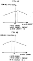
- FIGS. 4A and 4B each show the relationship between the higher harmonics current component and the combined motor efficiency achieved with the d-axis current id and q-axis current iq corresponding to the fundamental current components both set at a constant level.
- FIG. 4A shows the combined efficiency relative to the dh-axis current idh achieved by setting the qh axis current iqh to 0, whereas FIG. 4B shows the combined efficiency relative to the qh-axis current iqh achieved by setting the dh-axis current idh to 0.
- the maximum efficiency is not achieved when the higher harmonics current idh or iqh is set to 0 and the efficiency is maximized when there is some higher harmonics current flowing.
- the combined efficiency is improved by adopting a control method in which the higher harmonics currents are superimposed on the fundamental currents over a control method achieved by implementing motor drive control using the fundamental currents alone.
- FIG. 5 shows in detail the structure adopted in the torque control unit 1 in the first embodiment.
- the torque control unit 1 calculates a d-axis current command value id* corresponding to the torque command value Te* and the motor rotating speed we by looking up a maximum efficiency id map 1a.
- a maximum efficiency id map 1a d-axis current command value data relative to the torque command value Te* and the motor rotating speed we are stored.
- the torque control unit 1 calculates a q-axis current command value iq* corresponding to the torque command value Te* and the motor rotating speed ⁇ e by looking up a maximum efficiency iq map 1b.
- q-axis current command value data relative to the torque command value Te* and the motor rotating speed ⁇ e are stored.
- the torque control unit 1 calculates a dh-axis current command value idh* corresponding to the torque command value Te* and the motor rotating speed we by looking up a maximum efficiency idh map 1c.
- dh-axis current command value data relative to the torque command value Te* and the motor rotating speed we are stored.
- the torque control unit 1 also calculates a qh -axis current command value iqh* corresponding to the torque command value Te* and the motor rotating speed we by looking up a maximum efficiency iqh map Id.
- qh-axis current command value data relative to the torque command value Te* and the motor rotating speed we are stored.
- the fundamental current command values and the higher harmonics current command values that achieve the maximum combined efficiency among combinations of current command values for matching the motor torque Te to the torque command value Te* are stored.
- the combined motor efficiency is maximized in the motor control apparatus in the first embodiment by ensuring that the torque Te, which matches the torque command value Te* with a high degree of efficiency is output from the motor at any motor rotating speed ⁇ e.
- the torques expressed in the third term and the fourth term of the right member in expression (3) which each contain the product of an armature flux linkage and currents of different orders do not constitute contributing factors in the average torque, they constitute torque ripple components.
- the value of the fourth term is 0, but the value of the third term is not 0, thereby constituting a torque ripple component.
- the motor control apparatus in the related art is not capable of reducing the torque ripple in a motor manifesting a significant space harmonic. Since the torque ripple in the motor causes discomfort to passengers in an electric car, it is crucial to reduce the extent of torque ripple.
- the output torque Te of an IPM motor may be expressed as the sum of the magnet torque Tem and the reluctance torque Ter.
- Tem represents the magnet torque
- Ter represents the reluctance torque
- ⁇ dm represents the armature flux linkage (corresponding to the magnets)
- ⁇ dm_1 representing the fundamental wave component (corresponding to the magnets) of the armature flux linkage
- ⁇ dm_h representing the higher harmonics component
- the reluctance torque Ter is expressed as in the following expression (11).
- the first term in the right member in expression (11) represents the fundamental wave component of the reluctance torque and the second term and the third term in the right member each represent a torque ripple component. Accordingly, by implementing control on the currents so as to ensure that the sum of the second term and the third term is 0, the overall ripple component in the reluctance torque can be eliminated.
- the torque ripple in the motor can be reduced. Since the higher harmonics components id_h and iq_h in the dq-axis coordinate system can be converted to higher harmonics component currents along the dh-axis and the qh-axis in the higher harmonics coordinate system through expression (1), a dh-axis current command value idh* and a qh-axis current command value iqh* are calculated by incorporating expressions (10) and (13) into expression (1). By implementing control through the higher harmonics current control unit 11 so as to match the higher harmonics currents id_h and iq_h to the current command values idh* and iqh* respectively, the torque ripple in the motor can be minimized.
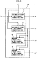
- FIG. 6 shows in detail the structure adopted in a torque control unit 1A in the second embodiment.
- the torque control unit 1A is employed instead of the torque control unit 1 shown in FIG. 1 .
- the torque control unit 1A calculates a d-axis current command value id* corresponding to the torque command value Te* and the motor rotating speed we by looking up a maximum efficiency id map 1e. In the maximum efficiency id map 1e, d-axis current command value data relative to the torque command value Te* and the motor rotating speed we are stored.
- the torque control unit 1A calculates a q-axis current command value iq* corresponding to the torque command value Te* and the motor rotating speed we by looking up a maximum efficiency iq map If. In the maximum efficiency iq map 1f, q-axis current command value data relative to the torque command value Te* and the motor rotating speed we are stored.
- the torque control unit 1A also calculates a dh-axis -current command value idh* corresponding to d-axis and q-axis current command values id* and iq* by looking up a minimum torque ripple idh map 1g.
- a minimum torque ripple idh map 1g dh-axis current command value data corresponding to the d-axis and q-axis current command values are stored.
- the torque control unit 1A calculates a qh-axis current command value iqh* corresponding to the d-axis and q-axis current command values id* and iq* by looking up a minimum torque ripple iqh map 1h.
- qh-axis current command value data relative the d-axis and q-axis current command values are stored.
- the fundamental current command values and the higher harmonics current command values that minimize the torque ripple while satisfying expressions (10) and (13) among combinations of current command values for matching the motor torque Te to the torque command value Te* are stored. Since an error occurs if these command values are ascertained through an arithmetic operation, data of measured values obtained by measuring the fundamental currents and the higher harmonics currents that achieve the minimum torque ripple in advance may be used.
- the torque Te that matches the torque command value Te* can be output from the motor while minimizing the torque ripple at any motor rotating speed ⁇ e.
- the motor vibration and the motor noise attributable to the torque ripple can be reduced.
- the passenger comfort is improved.
- the motor control apparatus achieved in the third embodiment minimizes the voltage ripple. It is to be noted that since the motor control apparatus in the third embodiment assumes a structure identical to the structure of the motor control apparatus in the first embodiment illustrated in FIG. 1 except for the structure adopted in the torque control unit 1, an explanation of the overall structure is omitted and the following explanation focuses on the difference.
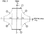
- FIG. 7 shows the relationship of the torque Te to the rotating speed ⁇ e of the motor M, i.e., the output characteristics of the motor M.
- the maximum torque of the motor M within the range over which the rotating speed ⁇ e is between the base rotating speed - ⁇ b and the base rotating speed + ⁇ b is indicated by the bold line 1 representing the maximum torque line.
- the maximum torque of the motor M in the range over which the rotating speed we exceeds the base rotating speed ⁇ b is identified by the dotted line 2 representing the maximum output line.
- a fundamental current up to 600A can be supplied in correspondence to, for instance, a 600A rated current.
- the motor current contains a higher harmonics current
- the peak value of the motor current becomes higher than the peak value of the fundamental current
- the fundamental current must be set lower than 600A, i.e., the rated current. This presents a problem in that the efficiency becomes poor due to increases in the core loss and the copper loss as well as the reduced maximum motor torque.
- the peak value of the motor voltage becomes higher than the peak value of the fundamental voltage and, accordingly, the fundamental voltage must be set lower than the rated voltage of the motor and the power element. This poses a problem in that due to an insufficient voltage, a predetermined level of electrical current cannot be supplied to result in a reduced output.
- a circuit equation of the motor M may be expressed as follows.
- vd representing the d-axis voltage
- vq representing the q-axis voltage
- R representing the phase winding resistance
- ⁇ d representing the d-axis armature flux linkage
- ⁇ q representing the q-axis armature flux linkage
- the first term represents the fundamental wave component and the second term represents the voltage ripple component.
- the voltage ripple may be eliminated by ensuring that the value of the second term is 0.
- the relationship expressed in the following expression (16) must be achieved.
- the ripple in the d-axis voltage vd may be eliminated by implementing control so as to set the higher harmonics components id_h in the d-axis current and iq_h in the q-axis current to the values expressed in expressions (17) and (18) respectively.
- the ripple in the q-axis voltage may be eliminated by ensuring that the value of the second term is 0.
- the ripple in the q-axis voltage vq may be eliminated by implementing control so as to set the higher harmonics components id_h in the d-axis current and iq_h in the q-axis current to the values expressed in expressions (21) and (22) respectively.
- the higher harmonics currents id_h and iq_h in the fundamental coordinate system dq can be converted to a dh-axis higher harmonics current idh and a qh- axis higher harmonics current iqh in the higher harmonics coordinate system dhqh through expression (1).
- expression (1) by incorporating expression (23) into expression (1) to calculate a dh-axis current command value idh* and a qh-axis current command value iqh* and implementing control on the higher harmonics currents accordingly as explained earlier, the voltage ripple can be minimized.
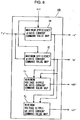
- FIG. 8 shows in detail the structure adopted in a torque control unit 1B in the third embodiment.
- the torque control unit 1B is employed instead of the torque control unit 1 shown in FIG. 1 .
- the torque control unit 1B calculates a d-axis current command value id* corresponding to the torque command value Te* and the motor rotating speed we by looking up a maximum efficiency id map 1e.
- d-axis current command value data relative to the torque command value Te* and the motor rotating speed we are stored.
- the torque control unit 1B calculates a q-axis current command value iq* corresponding to the torque command value Te* and the motor rotating speed we by looking up a maximum efficiency iq map If.
- q-axis current command value data relative to the torque command value and the motor rotating speed are stored.
- the torque control unit 1B also calculates a dh-axis current command value idh* corresponding to a d-axis current command value id* and a q-axis current command value iq* by looking up a minimum voltage ripple idh map 1i.
- dh-axis current command value data relative to the d-axis current command value and the q-axis current command value are stored.
- the torque control unit 1B calculates a qh-axis current command value iqh* corresponding to the d-axis current command value id* and the q-axis current command value iq* by looking up a minimum voltage ripple iqh map 1j.
- qh-axis current command value data relative to the d-axis and q-axis current command values are stored.
- the fundamental current command values and the higher harmonics current command values that minimize the voltage ripple among combinations of current command values for matching the motor torque Te to the torque command value Te* are stored. Since an error occurs if these command values are ascertained through an arithmetic operation, data of measured values obtained by measuring the fundamental currents and the higher harmonics currents that achieve minimum voltage ripple in advance may be used.
- the torque Te that matches the torque command value Te* can be output from the motor while minimizing the voltage ripple at any motor rotating speed we. As a result, the extent to which the fundamental voltage becomes reduced is minimized to achieve an increase in the motor output.
- the motor control apparatus achieved in the fourth embodiment minimizes the current ripple. It is to be noted that since the motor control apparatus in the fourth embodiment assumes a structure identical to the structure of the motor control apparatus in the first embodiment illustrated in FIG. 1 except for the structure adopted in the torque control unit 1, an explanation of the overall structure is omitted and the following explanation focuses on the difference.
- FIG. 9 shows in detail the structure adopted in a torque control unit 1C in the fourth embodiment.
- the torque control unit 1C is employed instead of the torque control unit shown in FIG. 1 .
- the torque control unit 1C calculates a d-axis current command value id* corresponding to the torque command value Te* and the motor rotating speed we by looking up a maximum efficiency id map 1e.
- d-axis current command value data relative to the torque command value Te* and the motor rotating speed we are stored.
- the torque control unit 1C calculates a q-axis current command value iq* corresponding to the torque command value Te* and the motor rotating speed we by looking up a maximum efficiency iq map If.
- q-axis current command value data relative to the torque command value Te and the motor rotating speed we are stored.
- the torque control unit 1C sets both the dh-axis current command value idh* and the qh-axis current command value iqh* to 0. This enables control for setting both the dh-axis current idh and the qh-axis current iqh in the higher harmonics coordinate system dhqh to 0.
- the torque Te that matches the torque command value Te* can be output from the motor while minimizing the current ripple at any motor rotating speed ⁇ e.
- the extent to which the fundamental current is lowered can be minimized by suppressing the current ripple, an increase in the motor torque is achieved in the constant torque control range.
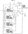
- FIG. 10 shows in detail the structure adopted in a torque control unit 1D in the fifth embodiment.
- the torque control unit 1D is employed instead of the torque control unit 1 shown in FIG. 1 .
- the torque control unit 1D is provided with a maximum efficiency current command calculation unit 1p, a minimum torque ripple current command calculation unit 1g, a minimum voltage ripple current command calculation unit 1r, a minimum current ripple current command calculation unit 1t, an optimal command value selection unit 1u and a selector switch 1v.
- the maximum efficiency current command calculation unit 1p calculates fundamental current command values id* and iq* and higher harmonics current command values idh* and iqh* that maximize the efficiency.
- the minimum torque ripple current command calculation unit 1g calculates fundamental current command values id* and iq* and higher harmonics current command values idh* and iqh* that minimize the torque ripple.
- the minimum voltage ripple current command calculation unit 1r calculates fundamental current command values id* and iq* and higher harmonics current command values idh* and iqh* that minimizes the voltage ripple.
- the minimum current ripple current command calculation unit 1t calculates fundamental current command values id* and iq* and higher harmonics current command values idh* and iqh* that minimizes the current ripple.
- the optimal command value selection unit 1u selects the optimal current command values from the current command values calculated at the current command calculation units 1p, 1q, 1r and 1t, in correspondence to the operating state of the motor M which includes the rotating speed we and the torque Te of the motor M, and switches the selector switch 1v.
- the torque Te of the motor M may be calculated through expression (3) or expression (6) mentioned earlier, for instance, or it may be measured by providing a torque detector.
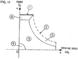
- FIG. 11 shows the first quadrant in FIG. 7 showing the output characteristics of the motor M. Since the operation achieved in the second ⁇ fourth quadrants is identical to the operation achieved over the first quadrant, an explanation thereof is omitted.
- the differences between the DC bus voltage (the invertor DC link voltage) and the motor voltages vu, vv and vw become reduced. Accordingly, when the operating point determined by the rotating speed we and the torque Te of the motor M is within the range 5 , i.e., when the difference between the motor output and the maximum output is equal to or less than a predetermined value and the motor output is close to the maximum value, the current command values calculated at the minimum voltage ripple current command calculation unit 1r are selected. As a result, the voltage ripple at the motor M is minimized to make it possible to prevent reductions in the motor voltages caused by ripple voltage while ensuring that the motor voltage peak value is lower than the voltage at the power element.
- the current command values calculated at the minimum torque ripple current command calculation unit 1g are selected. This minimizes the torque ripple at the motor M, which makes it possible to reduce discomfort to the passengers by lowering the extent of adverse effects attributable to the torque ripple such as vibration and noise in an electric car.
- the current command values calculated at the maximum efficiency current command calculation unit 1p for achieving the maximum efficiency are selected. This enables a reduction in the power consumption at the motor M while maximizing the efficiency of the motor M.
- drive control is implemented on the motor M by selecting the optimal current command values corresponding to the operating state of the motor M.
- the d-axis fundamental current command value id* and the q-axis fundamental current command value iq* and the dh-axis higher harmonics current command value idh* and the qh-axis higher harmonics current command value iqh* are calculated at the torque control unit 1, 1A, 1B and 1C based upon the torque command value Te* and the motor rotating speed we.
- the motor M is to be driven over the rotating speed (we) range of 0 - base rotating speed wb shown in FIG.
- the d-axis fundamental current command value id* and the q-axis fundamental current command value iq* and the dh-axis higher harmonics current command value idh* and the qh-axis higher harmonics current command value iqh* should be calculated based upon the torque command value Te* alone.
- the current command values id*, iq*, idh* and iqh* corresponding to a specific torque command value Te* should be calculated by looking up the map.
- a higher harmonics current control unit 11A implements control on the higher harmonics currents so as to reduce the higher harmonics components of the specific order as explained earlier among higher harmonics components contained in the motor currents iu, iv and iw. Namely, it sets both the dh-axis current command value idh* and the qh-axis current command value iqh* to 0.
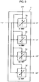
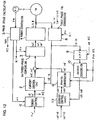
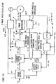
- FIG. 12 shows the structure adopted in the motor control apparatus in the sixth embodiment.
- the structural differences from the motor control apparatus in the first embodiment illustrated in FIG. 1 are in a torque control unit 1E and the higher harmonics current control unit 11A.
- the higher harmonics current control unit 11A implements control on the higher harmonics currents so as to ensure that the higher harmonics components of the specific order are 0 at all times.
- the torque control unit 1E calculates current command values id* and iq* by looking up current command value tables based upon the torque command value Te* and the motor rotating speed we.
- the current command values id* and iq* may be selected so as to maximize the motor efficiency as in the fourth embodiment or appropriate current command values id* and iq* may be selected from another viewpoint.
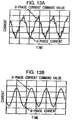
- FIG. 13A shows the waveform of the U-phase current relative to the U-phase current command value, which manifests when a concentrated winding IPM motor, in which a significant space harmonic component is present is driven by employing a motor control apparatus that implements motor control using the dq coordinate system alone.
- FIG. 13B shows the waveform of the U-phase current relative to the U-phase current command value manifesting when the same IPM motor is driven by employing the motor control apparatus in the sixth embodiment.
- FIG. 13A clearly indicates, a very significant higher harmonics component is contained in the motor current when motor control is implemented by using the dq coordinate system alone. In contrast, when the motor control apparatus in the sixth embodiment is utilized, the higher harmonics component is greatly reduced as shown in FIG. 13B .
- the higher harmonics currents contained in the motor currents iu, iv and iw and in particular, the higher harmonics components of the kth order and its vicinity, can be greatly reduced.
- the ultimate d-axis voltage command value (vd* +vd') and q-axis voltage command value (vq* + vq') are obtained by adding the d-axis vol tage command value vd' and the q-axis vol tage command value vq' corresponding to the higher harmonics components to the d-axis voltage command value vd* and the q-axis voltage command value vq* corresponding to the fundamental wave components respectively, and then, the d-axis and q-axis voltage command values are converted to three-phase voltage command values vu*, vv* and vw* through dq / three-phase conversion.
- three-phase AC voltage command values vu*, vv* and vw* corresponding to the fundamental wave components and three-phase AC voltage command values vu', vv' and vw' corresponding to the higher harmonics components are ascertained and then they are respectively added together to calculate ultimate three-phase AC voltage command values (vu* + vu'), (vv* + vv') and (vw* + vw').
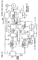
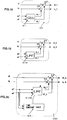
- FIG. 14 shows the structure adopted in the motor control apparatus in the seventh embodiment. It is to be noted that the same reference numerals are assigned to devices identical to those shown in FIG. 1 to preclude the necessity for a repeated explanation of thereof and that those devices are shown in single-line delineation. Since the fundamental current control circuit is similar to that in the first embodiment shown in FIG. 1 , its explanation is omitted.
- the high pass filter 9 extracts higher harmonics components by implementing filtering on the actual currents iu and iv at the three-phase alternating current motor M.
- a three-phase/dhqh conversion unit 21 includes a higher harmonics coordinate system dhqh and converts the higher harmonics components in the motor currents iu and iv to actual currents idh and iqh in the higher harmonics coordinate system dhqh.
- the higher harmonics coordinate system in this context refers to an orthogonal coordinate system that rotates at the frequency of a higher harmonics component of a specific order manifesting when the motor currents iu, iv and iw are controlled by the fundamental current control circuit alone, as explained earlier.
- ⁇ ehs represents the phase of the dhqh coordinate system viewed from the three-phase coordinate system.
- idh iqh 2 cos ⁇ ehs sin ⁇ ehs ⁇ sin ⁇ ehs cos ⁇ ehs sin ⁇ e + ⁇ 3 sin ⁇ e cos ⁇ e + ⁇ 3 cos ⁇ e iu iv
- a dhqh / three-phase conversion unit 22 converts a voltage command value vdh* along the dh-axis and a voltage command value vqh* corresponding to the qh-axis provided by the higher harmonics current control unit 11 to three-phase AC voltage command values vu', vv' and vw' corresponding to the higher harmonics components. This conversion may be achieved by reversing the conversion of formula (24).
- the adders 13 and 14 add the three-phase AC voltage command values vu*, vv* and vw* corresponding to the fundamental wave components calculated at the fundamental current control circuit to the three-phase AC voltage command values vu', vv' and vw' corresponding to the higher harmonics components calculated at the higher harmonics current control circuit and obtain the ultimate three-phase command values (vu* + vu'), (vv* + vv') and (vw* + vw').
- the voltage command values are calculated in the dq coordinate system and in the seventh embodiment, the voltage command values are calculated in the three-phase AC coordinate system. In the eighth embodiment, the voltage command values are calculated in an ⁇ coordinate system.
- the three-phase AC coordinate system mentioned earlier is a static coordinate system fixed to the motor stator, having axes that a U-phase, a V-phase and a W-phase which are sequentially offset from each other by 120°.
- the ⁇ coordinate system is an orthogonal coordinate system fixed to the stator. Normally, the ⁇ coordinate system is set by assuming an ⁇ -axis at the phase which is the same as the phase of the U-axis in the three-phase AC coordinate system. Since the three physical quantities in the three-phase AC coordinate system can be handled as two physical quantities that are perpendicular to each other in the ⁇ coordinate system, the volume of processing required to calculate the command values is roughly equal to the volume of the processing required in the dq coordinate system in the first embodiment.
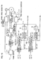
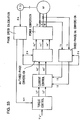
- FIG. 15 shows the structure adopted in the motor control apparatus in the eighth embodiment. It is to be noted that the same reference numerals are assigned to devices identical to those shown in FIG. 1 to preclude the necessity for a repeated explanation thereof and that such devices are shown in single-line delineation.
- the fundamental current control circuit in the seventh embodiment is achieved by adding a dq/ ⁇ conversion unit 31 and an ⁇ /three-phase conversion unit 32 to the fundamental current control circuit in FIG. 1 and replacing the three-phase/dq conversion unit 8 in FIG. 1 with a three-phase/ ⁇ conversion unit 33 and an ⁇ /dq conversion unit 34.
- the dq/ ⁇ conversion unit 31 converts fundamental voltage command values vd* and vq* corresponding to the d-axis and the q-axis respectively calculated at the fundamental current control unit 2 to fundamental voltage command values v ⁇ * and v ⁇ * corresponding to the ⁇ -axis and the ⁇ -axis respectively.
- the ⁇ /three-phase conversion unit 32 converts ultimate voltage command values (v ⁇ * + v ⁇ ') and (v ⁇ * + v ⁇ ') corresponding to the ⁇ -axis and the ⁇ -taxis to be detailed later to three-phase voltage command values vu*, vv* and vw* .
- the ⁇ /dq conversion unit 34 converts the actual currents i ⁇ and i ⁇ along the ⁇ -axis and the ⁇ -axis to actual currents id and iq along the d-axis and the q-axis.
- an ⁇ /dhqh conversion unit 35 and a dhqh / ⁇ conversion unit 36 are utilized instead of the dq/dhqh conversion unit 10 and the dhqh/dq conversion unit 12 in the higher harmonics current control circuit shown in FIG. 1 .
- the high pass filter 9 extracts the higher harmonics components by filtering the actual currents i ⁇ and i ⁇ along the ⁇ -axis and the ⁇ -axis.
- the extracted higher harmonics components are provided to the ⁇ /dhqh conversion unit 35.
- the ⁇ /dhqh conversion unit 35 which includes a higher harmonics coordinate system dhqh converts the higher harmonics components of the ⁇ -axis current i ⁇ and the ⁇ -axis current i ⁇ to actual currents idh and iqh in a higher harmonics coordinate system dhqh.
- the higher harmonics coordinate system is an orthogonal coordinate system that rotates at the frequency of the higher harmonics component of a specific order manifesting when the motor currents iu, iv and iw are controlled through the fundamental current control circuit alone.
- the dhqh/ ⁇ conversion unit 36 converts higher harmonics voltage command values vdh* and vqh* along the dh-axis and the qh-axis provided from the higher harmonics current control unit 11 to higher harmonics voltage command values v ⁇ ' and v ⁇ ' along the ⁇ -axis and the ⁇ -axis.
- the adders 13 and 14 add fundamental voltage command values v ⁇ * and v ⁇ * along the ⁇ -axis and the ⁇ -axis calculated at the fundamental current control circuit to higher harmonics voltage command values v ⁇ ' and v ⁇ ' along the ⁇ -axis and the ⁇ -axis calculated at the higher harmonics current control circuit to calculate ultimate voltage command values (v ⁇ * + v ⁇ ') and (v ⁇ * + v ⁇ ') along the ⁇ -axis and the ⁇ -taxis.
- the ultimate voltage command values (v ⁇ * + v ⁇ ') and (v ⁇ * + v ⁇ ') along the ⁇ -axis and the ⁇ -axis are converted to three-phase AC voltage command values vu*, vv* and vw* at the ⁇ /three-phase conversion unit 32.
- the power conversion unit 4 applies three-phase AC voltages U, V and W to the three-phase alternating current motor M in conformance to the three-phase AC voltage command values vu*, vv* and vw*.
- the higher harmonics component of a single order (the kth order) contained in a motor current is reduced.
- the current ripple is minimized by reducing higher harmonic components of two orders, i.e., mainly the higher harmonic components of the fifth order and the seventh order which are normally regarded as orders manifesting significant higher harmonics components.
- FIG. 16 shows the structure adopted in the motor control apparatus in the ninth embodiment. It is to be noted that the same reference numerals are assigned to devices identical to those shown in FIG. 1 to preclude the necessity for a repeated explanation thereof and that such devices are shown in single-line delineation.
- the structure adopted in the fundamental current control circuit in the ninth embodiment is identical to the structure of the fundamental current control circuit in the sixth embodiment.
- the motor control apparatus in the ninth embodiment differs from the motor control apparatus in the sixth embodiment in the structure adopted in its higher harmonics current control circuit. Namely, the motor control apparatus in the ninth embodiment is provided with two sets of the higher harmonics current control circuit utilized in the sixth embodiment.
- One of the higher harmonics current control circuit comprises a three-phase/dq conversion unit 8, a high pass filter 9, a dq/dh1qh1 conversion unit 10A, a higher harmonics current control unit 11 and a dh1qh1/dq conversion unit 12A.
- the other higher harmonics current control circuit comprises a three-phase/dq conversion unit 8, a high pass filter unit 9, a dq/dh2qh2 conversion unit 10B, a higher harmonics current control unit 11 and a dh2qh2/dq conversion unit 12B.
- the dq/dh1qh1 conversion unit 10A and the dq/dh2qh2 conversion unit 10B are both identical to the dq/dhqh conversion unit 10 shown in FIG. 1 .
- the dq/dh1qh1 conversion unit 10A converts the higher harmonics components of actual currents id and iq along the d-axis and q-axis to actual currents idh1 and iqh1 in an orthogonal coordinate system (higher harmonics coordinate system) dh1qh1 which rotates in synchronization with the phase ⁇ eh1 of the fifth-order higher harmonics components of the motor currents viewed from the dq coordinate system.
- the dq/dh2qh2 conversion unit 10B converts the higher harmonics components of the actual currents id and iq along the d-axis and q-axis to actual currents idh2 and iqh2 in an orthogonal coordinate system (higher harmonics coordinate system) dh2qh2 which rotates in synchronization the phase ⁇ eh2 of the seventh-order higher harmonics components of the motor currents viewed from the dq coordinate system.
- the dh1qh1/dq conversion unit 12A and the dh2qh2/dq conversion unit 12B are both identical to the dhqh/dq conversion unit 12 in FIG. 1 .
- the dh1qh1/dq conversion unit 12A converts higher harmonics voltage command values vdh1* and vqh1* along the dh1-axis and the qh1-axis to higher harmonics voltage command values vd1' and vq1' along the d-axis and the q-axis.
- the dh2qh2/dq conversion unit 12B converts higher harmonics voltage command values vdh2* and vqh2* along the dh2-axis and the qh2-axis to higher harmonics voltage command values vd2' and vq2' along the d-axis and the q-axis.
- the adders 13 and 14 add fundamental voltage command values vd* and vq* along the d-axis and the q-axis calculated at the fundamental current control circuit, higher harmonics voltage command values vd1' and vq1' along the d-axis and the q-axis calculated at the fifth-order higher harmonics current control circuit and higher harmonics voltage command values vd2' and vq2' along the d-axis and the q-axis calculated at the seventh-order higher harmonics current control circuit respectively to calculate ultimate voltage command values (vd* + vd1' + vd2') and (vq* + vq1' + vq2') along the d-axis and the q-axis.
- the ultimate voltage command values (vd* + vd1' + vd2') and (vq* + vq1' + vq2') along the d-axis and the q-axis are converted to three-phase AC voltage command values vu*, vv* and vw* at the dq/three-phase conversion unit 3.
- the power conversion unit 4 applies three-phase AC voltages U, V and W to the three-phase alternating current motor M in conformance to the three-phase AC voltage command values vu*, vv* and vw*.
- the higher harmonics components contained in the motor currents and, in particular, the higher harmonics components of the fifth order and the seventh order are reduced to an even further extent compared to the motor control apparatus in the sixth embodiment explained earlier.
- FIG. 17 shows the structure adopted in the motor control apparatus in the tenth embodiment. It is to be noted that the same reference numerals are assigned to devices identical to those shown in FIG. 1 to preclude the necessity for a repeated explanation thereof and that such devices are shown in single-line delineation.
- the structure adopted in the fundamental current control circuit is identical to the structure of the fundamental current control circuit in the first embodiment illustrated in FIG. 1 and its explanation is therefore omitted.
- the motor control apparatus in the tenth embodiment differs from the motor control apparatus shown in FIG. 1 in that it is provided with a higher harmonics current detection unit 50. Namely, while the high pass filter 9 is utilized to detect the higher harmonics components of the actual currents id and iq along the d-axis and the q-axis in the motor control apparatus in the first embodiment, the higher harmonics current detection unit 50 is employed to detect the higher harmonics components in the motor control apparatus in the ninth embodiment.
- the higher harmonics current detection unit 50 estimates current response values for the current command values id* and iq* and detects the higher harmonics components of the d-axis current id and the q-axis current iq using the estimated current response values and the d-axis current id and the q-axis current iq obtained through the conversion implemented at the three-phase/dq conversion unit 8.
- FIG. 18 is a block diagram showing the structure of the higher harmonics current detection unit 50.
- a current response estimating unit 51 has a transfer function G(s) for outputting estimated current response values id_i and iq_i corresponding to the d-axis and q-axis current command values id* and iq*.
- the transfer function G(s) may be realized through a low pass filter (LPF) 51a as shown in figure 19 .
- LPF low pass filter
- the time constant at the low pass filter 51a is equal to the time constant at the fundamental wave current control unit 2.
- the d-axis current command value id* and the q-axis current command value iq* are input to the current response estimating unit 51, and by utilizing the low pass filter 51a, for instance, the estimated current response values id_i and iq_i are ascertained to be output to subtractors 52 and 53 respectively.
- the subtractor 52 subtracts the estimated current response value id_i along the d-axis from the d-axis actual current id to calculate a higher harmonics component id_h of the d-axis current.
- the subtractor 53 subtracts the estimated current response value iq_i along the q-axis from the q-axis actual current iq to calculate the higher harmonics component iq_h of the q-axis current.
- the phase characteristics and the gain characteristics of the estimated current response values corresponding to the d-axis current command value id* and the q-axis current command value iq* are identical to the phase characteristics and the gain characteristics at the fundamental wave current control unit 2. If the fundamental wave current control unit 2 implements control other than PI control, a transfer function corresponding to the control system should be used.
- a change occurring in a fundamental current may pass through the high pass filter 9 and be detected as a higher harmonics component. If higher harmonics components are detected erroneously, an error occurs in the three-phase AC voltage command values vu*, vv* and vw* provided to the power conversion unit 4 resulting in reduced accuracy in the motor control.
- the higher harmonics components id_h and iq_h do not contain changes occurring in the fundamental currents even after such changes occur in the fundamental currents. Namely, since the estimated current response values id_i and iq_i, too, change if the d-axis current command value id* and the q-axis current command value iq* change, the higher harmonics components calculated at the subtractors 52 and 53 by subtracting the estimated current response values having undergone the changes do not reflect the changes in the fundamental currents.
- FIGS. 21 ⁇ 25 the control results obtained through a simulation implemented on the motor control apparatus in the first embodiment are compared against the control results obtained through a simulation implemented on the motor control apparatus in the tenth embodiment.
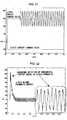
- FIG. 21 shows changes occurring in the d-axis current command value and the q-axis current command value over time.
- FIG. 22 presents the results of q-axis higher harmonics current detection implemented by using the motor control apparatus in the first embodiment in correspondence to the current command value shown in FIG. 21 .
- the scale of the vertical axis is -60 (A) - 150 (A).
- the detected q-axis higher harmonics current contains the change occurring in the fundamental current.
- FIG. 23 presents the results of q-axis higher harmonics current detection implemented by employing the motor control apparatus in the tenth embodiment in correspondence to the current command value shown in FIG. 21 .
- the scale of the vertical axis is -20 (A) ⁇ 20 (A).
- the detected q-axis higher harmonics current fluctuates only to a small degree, demonstrating that the change in the fundamental current is not included.
- the fluctuation of the d-axis current is suppressed through the control implemented by the motor control apparatus in the tenth embodiment, thereby achieving an improvement in the control accuracy.
- the response of the q-axis current to the current command values is improved.
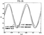
- FIG. 25 which is a partial enlargement of FIG. 24 , presents the results of the control achieved by the motor control apparatus in the first embodiment in conformance to the q-axis current command value and the results of the control implemented by the motor control apparatus in the tenth embodiment in conformance to the q-axis current command value.
- better control accuracy is achieved through the control implemented by the motor control apparatus in the tenth embodiment with regard to the response value of the q-axis current relative to the current command value.
- the control accuracy is compromised with regard to the control on both the d-axis current and the q-axis current. Since no fundamental current is contained in a detected higher harmonics current through the control implemented by the motor control apparatus in the tenth embodiment, the control accuracy with regard to the control on the d-axis current and the q-axis current is improved.
- the time constant of the low pass filter 51a employed in the motor control apparatus in the tenth embodiment is a fixed value which is equal to the time constant at the fundamental wave current control unit 2. This time constant may be a varied.
- the state of the motor M changes, e.g., the resistance of the motor M changes as the temperature fluctuates and the inductance changes in response to the motor currents.
- an error manifests as a deviation of the current response values relative to the current command values.
- the time constant at the low pass filter 51a may be varied to achieve an improvement in the detection accuracy with which the higher harmonics currents are detected.
- FIG. 20 is a block diagram of the structure of a higher harmonics current detection unit 50A having a variable time constant at the low pass filter 51a.
- a time constant table 54 is used to set the time constant of a low pass filter 51aA in correspondence to the command values id* and iq* along the d-axis and the q-axis. The relationship between the current command values id* and iq* and the time constant at the low pass filter 51aA is ascertained in advance through testing.
- the low pass filter 51aA implements filter processing by using the time constant obtained from the time constant table 54 and outputs the estimated current response values id_i and iq_i to the subtractors 52 and 53.
- the motor control apparatus in the tenth embodiment even when a change occurs in a fundamental current, the change in the fundamental current is not detected as a higher harmonics current, to enable a reliable detection of the higher harmonics current.
- the time constant at the low pass filter 51aA in correspondence to the current command values id* and iq*, an even more accurate higher harmonics current detection is enabled.
- time constant at the low pass filter 51aA stored in the time constant table 54 may be a value corresponding to the d-axis current id and the q-axis current iq instead of the current command values id* and iq*.
- the motor control apparatus in the tenth embodiment is achieved by replacing the high pass filter 9 in the motor control apparatus in the first embodiment with the higher harmonics current detection unit 50.
- the high pass filter 9 in the motor control apparatus in the seventh embodiment is replaced by a higher harmonics current detection unit 50B.
- it is provided with a dq/three-phase conversion unit 55 to input current command values iu* and iv* to the higher harmonics current detection unit 50B.
- FIG. 26 shows the structure adopted in the motor control apparatus in the eleventh embodiment.
- FIG. 27 is a block diagram showing the structure of the higher harmonics current detection unit 50B.
- the current command values iu* and iv* obtained through the conversion performed at the dq/three-phase conversion unit 55 are input to a low pass filter 51aB.
- the input current command values iu* and iv* undergo filter processing at the low pass filter 51aB to obtain estimated current response values iu_i and iv_i.
- the subtractor 52 subtracts a U-phase estimated current response value iu_i from the U-phase current iu to ascertain the higher harmonics component iu_h of the U-phase current.
- the subtractor 53 subtracts the V-phase estimated current response value iv_i from a V-phase current iv to ascertain a higher harmonics component iv_h of the V-phase current.
- the higher harmonics components iu_h and iv_h thus obtained are both output to the three-phase/dhqh conversion unit 21.
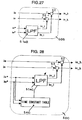
- FIG. 28 presents a block diagram of the structure of a higher harmonics current detection unit 50C with the low pass filter 51aB having a variable time constant.
- a time constant table 54C data of the time constant of a low pass filter 51aC are stored in correspondence to the U-phase current command value iu* and V-phase current command value iv*.
- time constant at the low pass filter 51aC stored in the time constant table 54C may be a value corresponding to the U-phase current iu and the V-phase current iv instead of the current command values iu* and iv*.
- the motor control apparatus in the eleventh embodiment achieves the advantages similar to those realized in the motor control apparatus in the tenth embodiment.
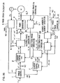
- FIG. 29 shows the structure adopted in the motor control apparatus in the twelfth embodiment.
- the motor control apparatus in the twelfth embodiment is achieved by replacing the high pass filter 9 in the motor control apparatus in the eighth embodiment with a higher harmonics current detection unit 50D.
- it is provided with a dq/ ⁇ conversion unit 56 to input current command values i ⁇ * and i ⁇ * to the higher harmonics current detection unit 50D.
- FIG. 30 is a block diagram showing the structure of the higher harmonics current detection unit 50D.
- Current command values i ⁇ * and i ⁇ * obtained through the conversion performed at the dq/ ⁇ conversion unit 56 are input to a low pass filter 51aD.
- the input current command values i ⁇ * and i ⁇ * undergo filter processing at the low pass filter 51aD to obtain estimated current response values i ⁇ _i and i ⁇ _i.
- the subtractor 52 subtracts an ⁇ -axis estimated current response value i ⁇ _i from an ⁇ -axis current i ⁇ to ascertain the higher harmonics component i ⁇ _h of the ⁇ -phase current.
- the subtractor 53 subtracts a ⁇ -phase estimated current response value i ⁇ _i from a ⁇ -axis current i ⁇ to ascertain the higher harmonics component i ⁇ _h of the ⁇ -axis current.
- the higher harmonics components i ⁇ _h and i ⁇ _h thus obtained are both output to the ⁇ /dhqh conversion unit 35.
- the time constant at the low pass filter 51aD may be varied as in the tenth and eleventh embodiments.
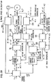
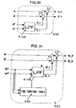
- FIG. 31 presents a block diagram of the structure of a higher harmonics current detection unit 50E with the low pass filter 51aE having a variable time constant.
- a time constant table 54E data of the time constant of a low pass filter 51aE corresponding to the ⁇ -axis current command value i ⁇ * and ⁇ -axis current command value i ⁇ *. Since advantages similar to those achieved by using a variable time constant at the low pass filter 51aA in the tenth and eleventh embodiments are realized by using a variable time constant at the low pass filter 51aE, a detailed explanation thereof is omitted.
- the motor control apparatus in the twelfth embodiment achieves the advantages similar to those realized in the motor control apparatuses in the tenth and eleventh embodiments.
- the motor control apparatus in the thirteenth embodiment is achieved by replacing the high pass filter 9 in the motor control apparatus in the ninth embodiment with a higher harmonics current detection unit 50.
- the structure adopted in the motor control apparatus in the thirteenth embodiment is shown in FIG. 32 .
- the structure of the higher harmonics current detection unit 50 which is identical to the higher harmonics current detection unit 50 utilized in the tenth embodiment, is as illustrated in FIGS. 18 and 19 .
- the structure that is adopted in the higher harmonics current detection unit 50 when variable time constant is used for the low pass filter 51a is shown in FIG. 20 .
- the motor control apparatus in the thirteenth embodiment too, achieves advantages similar to those realized in the motor control apparatuses in the tenth ⁇ twelfth embodiments.
- the present invention is not limited to the examples explained above.
- the order of the higher harmonics current components to undergo the control in the higher harmonics current control circuit in the motor control apparatuses in the first - thirteenth embodiments may be switched in correspondence to the motor control state such as the motor speed and the load applied to the motor.
- the motor control state such as the motor speed and the load applied to the motor.
- two sets of the higher harmonics control circuits in the motor control apparatus in the sixth embodiment are provided in the motor control apparatus in the ninth embodiment.
- two sets of the higher harmonics control circuits having the dh-axis current command value idh* and the qh-axis current command value iqh* set to 0 may be provided, and two sets of the higher harmonics control circuits having the dh-axis current command value idh* and the qh-axis current command value iqh* set to 0 may be provided in the motor control apparatus in the eighth embodiment as well.
- the high pass filter 9 may be replaced by the higher harmonics current detection unit 50 in any of these variations.
- the orders of the higher harmonics components to be reduced are not limited to these. In other words, an order at which significant higher harmonics components are present in the higher harmonics current should be reduced.
- the higher harmonics components of three orders or more may be reduced instead. In such a case, the number of higher harmonics current control circuit that should be provided corresponds to the number of orders of higher harmonics components to be reduced.
- the type of alternating current motor in conjunction with which the motor control apparatus according to the present invention may be adopted is not limited to a three-phase alternating current motor and the present invention may be adopted in a synchronous motors or an induction motor.
- a magnetic flux estimating instrument in the earlier technology should be provided to estimate the direction of the magnetic flux
- the dq coordinate system should be used as a coordinate system that rotates in synchronization with the estimated direction of the fundamental wave component of the magnetic flux
- the dhqh coordinate system to be used as a coordinate system that rotates in synchronization with the estimated direction of the higher harmonics order components of the magnetic flux.
Landscapes
- Engineering & Computer Science (AREA)
- Power Engineering (AREA)
- Control Of Ac Motors In General (AREA)
Claims (24)
- Motorsteuereinrichtung, umfassend:- eine Grundstrom-Befehlswert-Ermittlungseinrichtung (1) zum Ermitteln eines Grundstrom-Befehlswerts (id*, iq*) für den Motorstrom (iu, iv, iw);- Oberschwingungsstrom-Befehlswert-Ermittlungseinrichtung (1) zum Ermitteln eines Oberschwingungsstrom-Befehlswerts für den Motorstrom; und- eine Stromsteuereinrichtung (2, 11) zum Steuern eines zum Wechselstrommotor fließenden Stroms (iu, iv, iw) basierend auf dem Grundstrom-Befehlswert (id*, iq*) und dem Oberschwingungsstrom-Befehlswert, dadurch gekennzeichnet, dass
die Grundstrom-Befehlswert-Ermittlungseinrichtung (1) den Grundstrom-Befehlswert (id*, iq*) basierend auf zumindest einem Drehmoment-Befehlswert (Te*) für einen Wechselstrommotor (M) einstellt;
die Oberschwingungsstrom-Befehlswert-Ermittlungseinrichtung (1) den Oberschwingungsstrom-Befehlswert (idh*, iqh*) basierend auf zumindest einem Drehmoment-Befehlswert (Te*) des Wechselstrommotors (M) einstellt; und
die Stromsteuereinrichtung (2, 11) eine Grundwellenstrom-Steuereinrichtung (2) zum Implementieren einer Steuerung zum Anpassen einer Grundwellenkomponente des Motorstroms (iu, iv, iw) an den Grundstrom-Befehlswert (id*, iq*) in einem dq-Koordinatensystem, das sich synchron mit einer Grundwellenkomponente eines ankerverknüpften magnetischen Flusses dreht; und eine Oberschwingungsstrom-Steuereinrichtung (11) zum Implementieren einer Steuerung zum Anpassen einer Oberschwingungsordnungskomponente (idh, iqh) des Motorstroms (iu, iv, iw) an den Oberschwingungsstrom-Befehlswert (idh*, iqh*) in einem dhqh-Koordinatensystem umfasst, das sich synchron mit einer Oberschwingungsordnungskomponente des ankerverknüpften magnetischen Flusses dreht. - Motorsteuereinrichtung nach Anspruch 1, wobei:die Grundstrom-Befehlswert-Ermittlungseinrichtung (1) einen Grundstrom-Befehlswert (id*, iq*) in einem dq-Koordinatensystem ermittelt, das sich synchron mit einer Grundwellenkomponente eines ankerverknüpften magnetischen Flusses dreht; unddie Oberschwingungsstrom-Befehlswert-Ermittlungseinrichtung (1) einen Oberschwingungsstrom-Befehlswert (idh*, iqh*) in einem dhqh-Koordinatensystem ermittelt, das sich synchron mit einer Oberschwingungsordnungskomponente des ankerverknüpften magnetischen Flusses dreht.
- Motorsteuereinrichtung nach einem der vorhergehenden Ansprüche, wobei die Grundstrom-Befehlswert-Ermittlungseinrichtung (1) und die Oberschwingungsstrom-Befehlswert-Ermittlungseinrichtung (1) entsprechend einen Grundstrom-Befehlswert (id*, iq*) und einen Oberschwingungsstrom-Befehlswert (idh*, iqh*) ermitteln, der
eine Effizienz beim Anpassen eines Motordrehmoments an den Drehmoment-Befehlswert (Te*) maximiert. - Motorsteuereinrichtung nach Anspruch 1 oder 2, wobei die Grundstrom-Befehlswert-Ermittlungseinrichtung (1) und die Oberschwingungsstrom-Befehlswert-Ermittlungseinrichtung (1) entsprechend einen Grundstrom-Befehlswert (id*, iq*) und einen Oberschwingungsstrom-Befehlswert (idh*, iqh*) ermitteln, der
Drehmomentschwankungen beim Anpassen eines Motordrehmoments an den Drehmoment-Befehlswert (Te*) minimiert. - Motorsteuereinrichtung nach Anspruch 1 oder 2, wobei die Grundstrom-Befehlswert-Ermittlungseinrichtung (1) und die Oberschwingungsstrom-Befehlswert-Ermittlungseinrichtung (1) entsprechend einen Grundstrom-Befehlswert (id*, iq*) und einen Oberschwingungsstrom-Befehlswert (idh*, iqh*) ermitteln, der
Spannungsschwankungen beim Anpassen eines Motordrehmoments an den Drehmoment-Befehlswert (Te*) minimiert. - Motorsteuereinrichtung nach Anspruch 1 oder 2, wobei die Grundstrom-Befehlswert-Ermittlungseinrichtung (1) und die Oberschwingungsstrom-Befehlswert-Ermittlungseinrichtung (1) entsprechend einen Grundstrom-Befehlswert (id*, iq*) und einen Oberschwingungsstrom-Befehlswert (idh*, iqh*) ermitteln, der
Stromschwankungen beim Anpassen eines Motordrehmoments an den Drehmoment-Befehlswert (Te*) minimiert. - Motorsteuereinrichtung nach Anspruch 1 oder 2, wobei die Grundstrom-Befehlswert-Ermittlungseinrichtung (1) und die Oberschwingungsstrom-Befehlswert-Ermittlungseinrichtung (1) ermitteln
einen Grundstrom-Befehlswert (id*, iq*) und einen Oberschwingungsstrom-Befehlswert (idh*, iqh*), die eine Effizienz beim Anpassen eines Motordrehmoments an den Drehmoment-Befehlswert (Te*) maximieren,
einen Grundstrom-Befehlswert (id*, iq*) und einen Oberschwingungsstrom-Befehlswert (idh*, iqh*), die Drehmomentschwankungen beim Anpassen eines Motordrehmoments an den Drehmoment-Befehlswert (Te*) minimieren,
einen Grundstrom-Befehlswert (id*, iq*) und einen Oberschwingungsstrom-Befehlswert (idh*, iqh*), die Spannungsschwankungen beim Anpassen eines Motordrehmoments an den Drehmoment-Befehlswert (Te*) minimieren, und
einen Grundstrom-Befehlswert (id*, iq*) und einen Oberschwingungsstrom-Befehlswert (idh*, iqh*), die Stromschwankungen beim Anpassen eines Motordrehmoments an den Drehmoment-Befehlswert (Te*) minimieren; und
die Motorsteuereinrichtung ferner umfasst;
eine Betriebszustand-Erfassungseinrichtung (1, 5) zum Erfassen eines Motor-Betriebszustands (θeh, θe, ωe); und
eine Strombefehlswert-Auswahleinrichtung (1) zum Auswählen optimaler Strom-Befehlswerte (id*, iq*, idh*, iqh*), die dem MotorBetriebszustand (θeh, θe, ωe) entsprechen, aus Grundstrom-Befehlswerten (id*, iq*) und Oberschwingungsstrom-Befehlswerten (idh*, iqh*), die entsprechend durch die Grundstrom-Befehlswert-Ermittlungseinrichtung (1) und die Oberschwingungsstrom-Befehlswert-Ermittlungseinrichtung (1) ermittelt wurden. - Motorsteuereinrichtung nach Anspruch 7, wobei die Strombefehlswert-Auswahleinrichtung (1) den Grundstrom-Befehlswert (id*, iq*) und den Oberschwingungsstrom-Befehlswert (idh*, iqh*) zum Minimieren von Stromschwankungen beim Anpassen eines Motordrehmoments an den Drehmoment-Befehlswert (Te*) auswählt, wenn ein MotorBetriebszustand (θeh, ωe), bei dem das Motordrehmoment innerhalb eines bestimmten Bereichs nahe an einem Maximalwert liegt, erfasst wird.
- Motorsteuereinrichtung nach Anspruch 7, wobei die Strombefehlswert-Auswahleinrichtung (1) den Grundstrom-Befehlswert (id*, iq*) und den Oberschwingungsstrom-Befehlswert (idh*, iqh*) zum Minimieren von Drehmomentschwankungen beim Anpassen eines Motordrehmoments an den Drehmoment-Befehlswert (Te*) auswählt, wenn ein MotorBetriebszustand (θeh, θe, ωe), bei dem das Motordrehmoment und die Motordrehzahl (ωe) beide innerhalb eines bestimmten niedrigen Bereiches liegen, erfasst wird.
- Motorsteuereinrichtung nach Anspruch 7, wobei die Strombefehlswert-Auswahleinrichtung (1) den Grundstrom-Befehlswert (id*, iq*) und den Oberschwingungsstrom-Befehlswert (idh*, iqh*) zum Minimieren von Spannungsschwankungen beim Anpassen eines Motordrehmoments an den Drehmoment-Befehlswert (Te*) auswählt, wenn ein MotorBetriebszustand (θeh, θe, ωe), bei dem die Motorleistung innerhalb eines bestimmten Bereichs nahe an einem Maximalwert liegt, erfasst wird.
- Motorsteuereinrichtung nach Anspruch 7, wobei die Strombefehlswert-Auswahleinrichtung (1) den Grundstrom-Befehlswert (id*, iq*) und den Oberschwingungsstrom-Befehlswert (idh*, iqh*) zum Maximieren einer Effizienz beim Anpassen eines Motordrehmoments an den Drehmoment-Befehlswert (Te*) auswählt, wenn ein Betriebszustand (θeh, ωe), bei dem
ein Motordrehmoment und eine Motorleistung nicht innerhalb der bestimmten Bereiche liegen, über die das Motordrehmoment und die Motorleistung nahe an den Maximalwerten liegen, und
das Motordrehmoment und die Motordrehzahl nicht innerhalb der bestimmten niedrigen Bereiche liegen, erfasst wird. - Motorsteuereinrichtung nach Anspruch 1, wobei
die Oberschwingungsordnungskomponente (idh, iqh) eine Oberschwingungskomponente bestimmter Ordnung ist, die sich manifestiert, wenn der Motorstrom (iu, iv, iw) allein im dq-Koordinatensystem gesteuert wird; und
die Oberschwingungsstrom-Befehlswert-Ermittlungseinrichtung (1) einen Oberschwingungsstrom-Befehlswert (idh*, iqh*), welcher der bestimmten Ordnung in einer Oberschwingungskomponente (idh, iqh) entspricht, die im Motorstrom (iu, iv, iw) enthalten ist, auf 0 setzt. - Motorsteuereinrichtung nach Anspruch 12, wobei die einer Steuerung zu unterziehende Oberschwingungsordnungskomponente (idh, iqh) gemäß einem Motorantriebszustand (θeh, θe, ωe) geschaltet wird.
- Motorsteuereinrichtung nach Anspruch 1, wobei
die Oberschwingungsstrom-Steuereinrichtung (8, 10, 11, 50)
den Motorstrom (iu, iv, iw) in einen Strom (id, iq) im dq-Koordinatensystem umwandelt,
eine Oberschwingungskomponente des Stroms (id, iq) im dq-Koordinatensystem erfasst, der aus der Umwandlung resultiert, und
die Oberschwingungskomponente in einen Oberschwingungsstrom (idh, iqh) im dhqh-Koordinatensystem umwandelt. - Motorsteuereinrichtung nach Anspruch 1, wobei die Oberschwingungsstrom-Steuereinrichtung (11, 21, 50B)
eine Oberschwingungskomponente des Motorstroms (iu, iv, iw) erfasst, und
die Oberschwingungskomponente in einen Oberschwingungsstrom (idh, iqh) im dhqh-Koordinatensystem umwandelt. - Motorsteuereinrichtung nach Anspruch 1, wobei die Oberschwingungsstrom-Steuereinrichtung (11, 33, 35, 50D) den Motorstrom in einen Strom (iu, iv, iw) in einem orthogonalen Alpha-Beta-Koordinatensystem, das an einem Stator des Wechselstrommotors (M) fixiert ist, umwandelt,
eine Oberschwingungskomponente des Stroms (iα, iβ) im Alpha-Beta-Koordinatensystem erfasst, und
die erfasste Oberschwingungskomponente in einen Oberschwingungsstrom (idh, iqh) im dhqh-Koordinatensystem umwandelt. - Motorsteuereinrichtung nach Anspruch 14, wobei die Oberschwingungsstrom-Steuereinrichtung (8, 10, 11, 50) umfasst:eine Stromansprechwert-Schätzeinrichtung (51, 51a) zum Schätzen eines Stromansprechwerts relativ zu einem Strombefehlswert im dq-Koordinatensystem; undeine Oberschwingungsstrom-Erfassungseinrichtung (50) zum Erfassen eines Oberschwingungsstroms durch Subtrahieren des Stromansprechwerts, der von der Stromansprechwert-Schätzeinrichtung (51, 51a) geschätzt wurde, vom Stromwert im dq-Koordinatensystem.
- Motorsteuereinrichtung nach Anspruch 15, wobei die Oberschwingungsstrom-Steuereinrichtung (11, 21, 50D) umfasst:eine Stromansprechwert-Schätzeinrichtung (51aB) zum Schätzen eines Stromansprechwerts relativ zu einem Motorstrom-Befehlswert; undeine Oberschwingungsstrom-Erfassungseinrichtung (50B) zum Erfassen eines Oberschwingungsstroms durch Subtrahieren des Stromansprechwerts, der von der Stromansprechwert-Schätzeinrichtung geschätzt wurde, vom Grundstromwert.
- Motorsteuereinrichtung nach Anspruch 16, wobei die Oberschwingungsstrom-Steuereinrichtung (11, 33, 35, 50D) umfasst:eine Stromansprechwert-Schätzeinrichtung (51aD) zum Schätzen eines Stromansprechwerts relativ zu einem Strombefehlswert im Alpha-Beta-Koordinatensystem; undeine Oberschwingungsstrom-Erfassungseinrichtung (50D) zum Erfassen eines Oberschwingungsstroms durch Subtrahieren des Stromansprechwerts, der von der Stromansprechwert-Schätzeinrichtung (51aD) geschätzt wurde, vom Stromwert im Alpha-Beta-Koordinatensystem.
- Motorsteuereinrichtung nach einem der Ansprüche 17 bis 19, wobei die Stromansprechwert-Schätzeinrichtung (51, 51a) ein Tiefpassfilter (51a) ist.
- Motorsteuereinrichtung nach Anspruch 20, wobei sich eine Zeitkonstante im Tiefpassfilter verändert, wenn sich ein Motorzustand (θeh, θe, ωe) verändert.
- Motorsteuereinrichtung nach einem der Ansprüche 12 bis 21, die eine Vielzahl der Oberschwingungsstrom-Steuereinrichtungen (11) aufweist, die gemäß einer Vielzahl von Ordnungen von Oberschwingungsströmen vorgesehen sind.
- Motorsteuereinrichtung nach Anspruch 22, wobei die Reihenfolge, in der die Oberschwingungen der Vielzahl von Ordnungen einer Steuerung in der Oberschwingungsstrom-Steuereinrichtung (11) unterzogen werden, durch Vergeben einer höheren Priorität an Ordnungen bestimmt ist, bei denen sich größere Oberschwingungskomponenten im Motorströmen manifestieren.
- Motorsteuerverfahren, umfassend:Ermitteln eines Grundstrom-Befehlswerts (id*, iq*) für einen Motorstrom (iu, iv, iw) basierend auf zumindest einem Drehmoment-Befehlswert (Te*) für einen Wechselstrommotor (M);Ermitteln eines Oberschwingungsstrom-Befehlswerts für den Motorstrom basierend auf zumindest einem Drehmoment-Befehlswert (Te*) des Wechselstrommotors (M); undSteuern des Stroms (iu, iv, iw), der durch den Wechselstrommotor (M) fließt, basierend auf dem Grundstrom-Befehlswert (id*, iq*) und dem Oberschwingungsstrom-Befehlswert,gekennzeichnet durchImplementieren einer Steuerung zum Anpassen einer Grundwellenkomponente des Motorstroms (iu, iv, iw) an den Grundstrom-Befehlswert (id*, iq*) in einem dq-Koordinatensystem, das sich synchron mit einer Grundwellenkomponente eines ankerverknüpften magnetischen Flusses dreht; und Implementieren einer Steuerung zum Anpassen einer Oberschwingungsstrom-Steuereinrichtung (11) zum Implementieren einer Steuerung zum Anpassen einerOberschwingungsordnungskomponente (idh, iqh) des Motorstroms (iu, iv, iw) an den Oberschwingungsstrom-Befehlswert (idh*, iqh*) in einem dhqh-Koordinatensystem, das sich synchron mit einer Oberschwingungsordnungskomponente des ankerverknüpften magnetischen Flusses dreht.
Applications Claiming Priority (6)
| Application Number | Priority Date | Filing Date | Title |
|---|---|---|---|
| JP2000356117 | 2000-11-22 | ||
| JP2000356117 | 2000-11-22 | ||
| JP2001040550 | 2001-02-16 | ||
| JP2001040550A JP3852289B2 (ja) | 2001-02-16 | 2001-02-16 | モーター制御装置 |
| JP2001276887A JP3809783B2 (ja) | 2000-11-22 | 2001-09-12 | モータ制御装置 |
| JP2001276887 | 2001-09-12 |
Publications (3)
| Publication Number | Publication Date |
|---|---|
| EP1211798A2 EP1211798A2 (de) | 2002-06-05 |
| EP1211798A3 EP1211798A3 (de) | 2002-09-25 |
| EP1211798B1 true EP1211798B1 (de) | 2018-01-10 |
Family
ID=27345246
Family Applications (1)
| Application Number | Title | Priority Date | Filing Date |
|---|---|---|---|
| EP01126007.2A Expired - Lifetime EP1211798B1 (de) | 2000-11-22 | 2001-10-31 | Methode und Vorrichtung zur Motorsteuerung |
Country Status (2)
| Country | Link |
|---|---|
| US (1) | US6674262B2 (de) |
| EP (1) | EP1211798B1 (de) |
Families Citing this family (78)
| Publication number | Priority date | Publication date | Assignee | Title |
|---|---|---|---|---|
| JP3627683B2 (ja) * | 2001-06-29 | 2005-03-09 | 日産自動車株式会社 | モーター制御装置 |
| JP3582505B2 (ja) * | 2001-09-10 | 2004-10-27 | 日産自動車株式会社 | モーター制御装置 |
| JP3722048B2 (ja) * | 2001-11-15 | 2005-11-30 | 日産自動車株式会社 | モーター制御装置 |
| JP2003244992A (ja) * | 2002-02-21 | 2003-08-29 | Nissan Motor Co Ltd | 回転電機の電流制御方法 |
| JP3661864B2 (ja) * | 2002-03-19 | 2005-06-22 | 日本サーボ株式会社 | ステッピングモータの駆動装置 |
| WO2003081765A1 (fr) * | 2002-03-22 | 2003-10-02 | Matsushita Electric Industrial Co., Ltd. | Dispositif de commande d'un moteur a reluctance synchrone |
| WO2004055967A1 (ja) * | 2002-10-17 | 2004-07-01 | Denso Corporation | 交流回転電機の磁気騒音低減方法、それを用いるモータ制御装置及び交流回転電機装置 |
| JP3783695B2 (ja) * | 2003-03-20 | 2006-06-07 | 日産自動車株式会社 | モーター制御装置 |
| JP3928575B2 (ja) * | 2003-04-07 | 2007-06-13 | 日産自動車株式会社 | モーター制御装置 |
| EP1480330A3 (de) * | 2003-05-22 | 2007-09-26 | Jtekt Corporation | Vorrichtung und Verfahren zur steuerung eines Motors |
| FR2855678B1 (fr) * | 2003-06-02 | 2005-07-22 | Alstom | Procede et systeme de regulation du couple electromagnetique moyen d'une machine electrique tournante, support d'enregistrement et structure de donnees pour la mise en oeuvre du procede |
| FR2855679B1 (fr) * | 2003-06-02 | 2005-07-22 | Alstom | Procede et systeme de regulation du couple electromagnetique instantane, et support d'enregistrement pour la mise en oeuvre du procede |
| KR100608656B1 (ko) * | 2003-09-20 | 2006-08-04 | 엘지전자 주식회사 | 모터의 속도제어장치 |
| US7474067B2 (en) * | 2003-10-07 | 2009-01-06 | Jtekt Corporation | Electric power steering system |
| JP2005328691A (ja) * | 2004-04-15 | 2005-11-24 | Denso Corp | モータ制御装置 |
| JP4531751B2 (ja) * | 2004-05-14 | 2010-08-25 | 三菱電機株式会社 | 同期機制御装置 |
| JP4422567B2 (ja) * | 2004-06-30 | 2010-02-24 | 株式会社日立製作所 | モータ駆動装置,電動アクチュエータおよび電動パワーステアリング装置 |
| US7161316B2 (en) * | 2004-11-02 | 2007-01-09 | General Electric Company | Method and apparatus for discrete speed compensated torque step motor control |
| US7348756B2 (en) * | 2004-11-30 | 2008-03-25 | Honeywell International Inc. | Advanced current control method and apparatus for a motor drive system |
| JP2006238631A (ja) * | 2005-02-25 | 2006-09-07 | Mitsubishi Heavy Ind Ltd | Id/Iqテーブルを使用したモータの制御方法 |
| JP4706324B2 (ja) * | 2005-05-10 | 2011-06-22 | トヨタ自動車株式会社 | モータ駆動システムの制御装置 |
| US7786691B2 (en) * | 2006-10-24 | 2010-08-31 | Unico, Inc. | Bus disturbance regulator |
| US7545113B2 (en) * | 2006-10-24 | 2009-06-09 | Unico, Inc. | Harmonic disturbance regulator |
| JP5167631B2 (ja) * | 2006-11-30 | 2013-03-21 | 株式会社デンソー | モータの制御方法及びそれを利用するモータ制御装置 |
| US8018193B1 (en) * | 2006-12-07 | 2011-09-13 | Purdue Research Foundation | Torque ripple mitigation controller with vibration sensor delay compensation |
| US7997144B1 (en) | 2007-05-11 | 2011-08-16 | Purdue Research Foundation | System and method of measuring quasi-static force with a piezoelectric sensor |
| US8390240B2 (en) * | 2007-08-06 | 2013-03-05 | GM Global Technology Operations LLC | Absolute position sensor for field-oriented control of an induction motor |
| EP2200175A1 (de) * | 2008-12-19 | 2010-06-23 | Siemens Aktiengesellschaft | Vorrichtung und Verfahren zur Minimierung eines dynamischen Schleppfehlers |
| EP2230204A1 (de) * | 2009-03-20 | 2010-09-22 | Inventio AG | Treibscheibenaufzug, Aufzugsantrieb für einen solchen Treibscheibenaufzug und Verfahren zum Betreiben eines solchen Aufzugsantriebs |
| JP4900738B2 (ja) * | 2009-06-30 | 2012-03-21 | アイシン・エィ・ダブリュ株式会社 | 電動機駆動制御装置 |
| CN101820281B (zh) * | 2010-04-15 | 2011-11-16 | 西安交通大学 | 基于双park变换鉴相器的单相锁相环及其实现方法 |
| IT1400456B1 (it) * | 2010-06-04 | 2013-05-31 | St Microelectronics Srl | Metodo di controllo di un motore sincrono trifase a magneti permanenti per ridurre il rumore acustico e relativo dispositivo di controllo |
| US8080956B2 (en) * | 2010-08-26 | 2011-12-20 | Ford Global Technologies, Llc | Electric motor torque estimation |
| JP5522476B2 (ja) * | 2010-12-10 | 2014-06-18 | アイシン・エィ・ダブリュ株式会社 | 制御装置 |
| DK2485388T3 (da) * | 2011-02-04 | 2013-07-29 | Siemens Ag | Reduktion af støj og vibrationer af en elektromekanisk transducer under anvendelse af et modificeret statorspoledrivsignal omfattende harmoniske komponenter |
| FR2971377B1 (fr) * | 2011-02-09 | 2013-02-01 | Renault Sa | Procede et dispositif de pilotage d'une machine electrique a reluctance |
| US8648555B2 (en) * | 2011-02-28 | 2014-02-11 | Deere & Company | Method and system for controlling an electric motor at or near stall conditions |
| FR2974466B1 (fr) * | 2011-04-19 | 2013-12-20 | Valeo Sys Controle Moteur Sas | Procede de commande d'un moteur electrique et dispositif electrique correspondant |
| US20120274251A1 (en) | 2011-04-29 | 2012-11-01 | Danfoss Drives A/S | Harmonic noise reduction |
| GB201109348D0 (en) * | 2011-06-03 | 2011-07-20 | Trw Ltd | Motor control with voltage harmonic shaping |
| US8519648B2 (en) * | 2011-07-22 | 2013-08-27 | GM Global Technology Operations LLC | Temperature compensation for improved field weakening accuracy |
| JP5447590B2 (ja) | 2011-08-31 | 2014-03-19 | 株式会社デンソー | 回転機の制御装置 |
| US8786223B2 (en) * | 2011-10-14 | 2014-07-22 | Ford Global Technologies, Llc | Controlling torque ripple in interior permanent magnet machines |
| US20130119900A1 (en) * | 2011-11-10 | 2013-05-16 | Ford Global Technologies, Llc | Motor torque ripple compensation |
| CN102780433B (zh) * | 2012-07-10 | 2014-10-15 | 燕山大学 | 一种基于电流控制的无刷直流电机瞬时转矩控制方法 |
| US8981692B2 (en) | 2012-07-19 | 2015-03-17 | GM Global Technology Operations LLC | Torque ripple reduction of multiple harmonic components |
| JP5880967B2 (ja) * | 2012-09-28 | 2016-03-09 | 株式会社デンソー | 交流電動機の制御装置 |
| JP6064207B2 (ja) | 2012-12-17 | 2017-01-25 | 株式会社ミツバ | ブラシレスモータ制御方法及びブラシレスモータ制御装置並びに電動パワーステアリング装置 |
| JP5700059B2 (ja) * | 2013-02-08 | 2015-04-15 | 株式会社デンソー | 交流電動機の制御装置 |
| WO2014174682A1 (ja) * | 2013-04-26 | 2014-10-30 | 三菱電機株式会社 | 永久磁石電動機の磁石温度推定装置および永久磁石電動機の磁石温度推定方法 |
| KR101452633B1 (ko) * | 2013-05-20 | 2014-10-22 | 엘에스산전 주식회사 | 인버터 |
| CN104579042A (zh) * | 2013-10-22 | 2015-04-29 | 广东美的制冷设备有限公司 | 永磁同步电机的控制系统及其力矩波动抑制方法 |
| FR3022415A1 (fr) * | 2014-06-17 | 2015-12-18 | Renault Sas | Methode de pilotage d'une machine synchrone a reluctance variable et machine equipee d'un systeme de pilotage correspondant |
| KR101601444B1 (ko) * | 2014-07-04 | 2016-03-21 | 현대자동차주식회사 | 모터 구동 시스템의 인버터 6-스텝 제어 장치 및 방법 |
| US9419553B2 (en) | 2014-07-25 | 2016-08-16 | Denso Corporation | Apparatus for controlling rotary machine |
| JP6221981B2 (ja) | 2014-07-25 | 2017-11-01 | 株式会社デンソー | 回転電機の制御装置 |
| EP3043467A1 (de) * | 2015-01-12 | 2016-07-13 | Siemens Aktiengesellschaft | Regelung einer Antriebsvorrichtung |
| JP6384355B2 (ja) * | 2015-02-19 | 2018-09-05 | 株式会社デンソー | Srモータの制御装置 |
| CN106685299B (zh) * | 2015-11-04 | 2019-05-14 | 湖南大学 | 内置式永磁同步电机电流控制方法 |
| JP6540538B2 (ja) | 2016-02-24 | 2019-07-10 | 株式会社デンソー | 交流電動機の制御装置 |
| GB201604663D0 (en) * | 2016-03-18 | 2016-05-04 | Trw Ltd | Control system for electric motor |
| EP3264593B1 (de) * | 2016-06-30 | 2018-10-17 | Siemens Aktiengesellschaft | Steuerungsanordnung für einen generator |
| DE102016217887A1 (de) | 2016-09-19 | 2018-03-22 | Siemens Aktiengesellschaft | Regelanordnung für einen Generator |
| KR101846709B1 (ko) * | 2016-09-20 | 2018-04-06 | 현대자동차주식회사 | 가변 전류제어기 게인 방식 모터 제어방법 및 친환경 차량 |
| DE102016222214A1 (de) * | 2016-11-11 | 2018-05-17 | Brose Fahrzeugteile GmbH & Co. Kommanditgesellschaft, Würzburg | Verfahren zur Bestimmung eines mehrphasigen Motorstroms und elektromotorischer Antrieb |
| DK3454469T3 (da) * | 2017-09-12 | 2022-03-21 | Siemens Gamesa Renewable Energy As | Drejningsmoment-ripple-reduktion for en generator og vindmølle indbefattende samme |
| JP6867931B2 (ja) * | 2017-11-07 | 2021-05-12 | 株式会社コロナ | モータ制御装置及び空気調和装置 |
| JP7040335B2 (ja) * | 2018-07-24 | 2022-03-23 | トヨタ自動車株式会社 | モータの制御方法 |
| JP6854849B2 (ja) * | 2019-06-19 | 2021-04-07 | 三菱電機株式会社 | 電流検出装置および電流検出装置の製造方法 |
| DE102019218543A1 (de) * | 2019-11-29 | 2021-06-02 | Robert Bosch Gmbh | Verfahren und Vorrichtung zur Regelung einer elektrischen Maschine |
| DE102019218553A1 (de) * | 2019-11-29 | 2021-06-02 | Robert Bosch Gmbh | Verfahren und Vorrichtung zur Regelung einer elektrischen Maschine |
| DE102019218544A1 (de) | 2019-11-29 | 2021-06-02 | Robert Bosch Gmbh | Verfahren und Vorrichtung zur Regelung einer elektrischen Maschine |
| CN111800043B (zh) * | 2020-06-27 | 2021-10-08 | 同济大学 | 一种凸级式同步电机谐波电流解耦控制系统及方法 |
| KR20220026689A (ko) * | 2020-08-26 | 2022-03-07 | 현대자동차주식회사 | 친환경 차량의 모터 소음 저감 제어 장치 및 방법 |
| CN113507243B (zh) * | 2021-07-20 | 2022-08-30 | 燕山大学 | 基于谐波分解的永磁无刷电机高性能运行控制方法及系统 |
| CN113809959B (zh) * | 2021-09-29 | 2023-06-06 | 蔚来动力科技(合肥)有限公司 | 抑制车辆高阶噪声的谐波电流注入方法、计算机可读存储介质和装置 |
| CN113765444B (zh) * | 2021-09-29 | 2023-06-02 | 蔚来动力科技(合肥)有限公司 | 抑制车辆低速抖动的谐波电流注入方法、装置和计算机可读存储介质 |
| DE102022207862A1 (de) | 2022-07-29 | 2024-02-01 | Zf Friedrichshafen Ag | Verfahren zur Steuerung des Betriebs einer elektrischen Maschine |
Family Cites Families (9)
| Publication number | Priority date | Publication date | Assignee | Title |
|---|---|---|---|---|
| US4115726A (en) * | 1977-01-04 | 1978-09-19 | Hewlett-Packard Company | Open-loop electric drive with corrective controller |
| US4980617A (en) * | 1988-02-24 | 1990-12-25 | Hitachi, Ltd. | Speed control apparatus of movable equipment |
| US5485071A (en) * | 1993-08-09 | 1996-01-16 | Bi; Chao | Method and apparatus for establishing a reference current for use in operating a synchronous motor |
| JPH08331885A (ja) * | 1995-05-29 | 1996-12-13 | Toyota Motor Corp | 同期モータ制御装置および制御方法 |
| US6025691A (en) * | 1995-05-29 | 2000-02-15 | Toyota Jidosha Kabushiki Kaisha | Synchronous motor control system and method of controlling synchronous motor |
| DE69739441D1 (de) | 1996-08-19 | 2009-07-16 | Daikin Ind Ltd | Antriebsvorrichtung für einen bürstenlosen gleichstrommotor |
| FI974413A (fi) * | 1997-12-03 | 1999-06-04 | Kone Corp | Kestomagneettimoottorin säätö ja säätäjä |
| JP3366858B2 (ja) * | 1998-05-29 | 2003-01-14 | 株式会社日立製作所 | 回転電機の制御装置 |
| US6426605B1 (en) * | 1999-07-16 | 2002-07-30 | The Texas A&M University System | Multi-phase induction motor drive system and method |
-
2001
- 2001-10-31 EP EP01126007.2A patent/EP1211798B1/de not_active Expired - Lifetime
- 2001-11-07 US US09/986,086 patent/US6674262B2/en not_active Expired - Lifetime
Non-Patent Citations (1)
| Title |
|---|
| None * |
Also Published As
| Publication number | Publication date |
|---|---|
| EP1211798A2 (de) | 2002-06-05 |
| US6674262B2 (en) | 2004-01-06 |
| US20020097015A1 (en) | 2002-07-25 |
| EP1211798A3 (de) | 2002-09-25 |
Similar Documents
| Publication | Publication Date | Title |
|---|---|---|
| EP1211798B1 (de) | Methode und Vorrichtung zur Motorsteuerung | |
| US6771039B2 (en) | Motor control apparatus and method | |
| EP1748550B1 (de) | Synchron-maschinensteuerung | |
| US7932692B2 (en) | Control system for rotary electric machine with salient structure | |
| US6650081B2 (en) | Synchronous motor driving system | |
| US7045988B2 (en) | Sensorless controller of AC motor and control method | |
| US6768280B2 (en) | Motor control apparatus | |
| US8872454B2 (en) | Control unit of rotary device | |
| EP1940016B1 (de) | Motorsteuervorrichtung und Motorsteuerverfahren | |
| US10778130B2 (en) | Control apparatus for alternating-current rotary electric machine | |
| CA2594124C (en) | Electric vehicle control device | |
| JP3809783B2 (ja) | モータ制御装置 | |
| EP2333948A2 (de) | Invertersteuerung und Motorsteuersystem | |
| US9077265B2 (en) | Motor control device | |
| US20100277111A1 (en) | Permanent magnet synchronization motor vector control device | |
| JPWO2003081765A1 (ja) | シンクロナスリラクタンスモータの制御装置 | |
| US7075266B2 (en) | Apparatus for controlling an a. c. motor | |
| US20080048606A1 (en) | Vector controller for a permanent magnet motor and inverter module | |
| JP3852289B2 (ja) | モーター制御装置 | |
| CN113646204B (zh) | 永磁体同步电机的驱动装置、永磁体同步电机的转矩补偿方法和电动车 | |
| JP4135753B2 (ja) | モーター制御装置およびモーター制御方法 | |
| EP4131770A1 (de) | Motorsteuerungsvorrichtung | |
| JP2009044908A (ja) | 回転機の回転角度推定装置及び駆動システム | |
| CN109412490B (zh) | 电器设备、电机控制系统及感应电机的控制方法、装置 | |
| EP3787174B1 (de) | Pulsmustererzeugungsvorrichtung |
Legal Events
| Date | Code | Title | Description |
|---|---|---|---|
| PUAI | Public reference made under article 153(3) epc to a published international application that has entered the european phase |
Free format text: ORIGINAL CODE: 0009012 |
|
| 17P | Request for examination filed |
Effective date: 20011031 |
|
| AK | Designated contracting states |
Kind code of ref document: A2 Designated state(s): AT BE CH CY DE DK ES FI FR GB GR IE IT LI LU MC NL PT SE TR |
|
| AX | Request for extension of the european patent |
Free format text: AL;LT;LV;MK;RO;SI |
|
| PUAL | Search report despatched |
Free format text: ORIGINAL CODE: 0009013 |
|
| AK | Designated contracting states |
Kind code of ref document: A3 Designated state(s): AT BE CH CY DE DK ES FI FR GB GR IE IT LI LU MC NL PT SE TR |
|
| AX | Request for extension of the european patent |
Free format text: AL;LT;LV;MK;RO;SI |
|
| RIC1 | Information provided on ipc code assigned before grant |
Free format text: 7H 02P 21/00 A, 7H 02P 6/10 B, 7H 02P 6/08 B |
|
| AKX | Designation fees paid |
Designated state(s): DE FR GB |
|
| 17Q | First examination report despatched |
Effective date: 20090916 |
|
| REG | Reference to a national code |
Ref country code: DE Ref legal event code: R079 Ref document number: 60150742 Country of ref document: DE Free format text: PREVIOUS MAIN CLASS: H02P0021000000 Ipc: H02P0021020000 |
|
| RIC1 | Information provided on ipc code assigned before grant |
Ipc: H02P 21/06 20160101ALI20170615BHEP Ipc: H02P 21/02 20060101AFI20170615BHEP Ipc: H02P 6/10 20060101ALI20170615BHEP |
|
| GRAP | Despatch of communication of intention to grant a patent |
Free format text: ORIGINAL CODE: EPIDOSNIGR1 |
|
| INTG | Intention to grant announced |
Effective date: 20171018 |
|
| GRAS | Grant fee paid |
Free format text: ORIGINAL CODE: EPIDOSNIGR3 |
|
| GRAA | (expected) grant |
Free format text: ORIGINAL CODE: 0009210 |
|
| AK | Designated contracting states |
Kind code of ref document: B1 Designated state(s): DE FR GB |
|
| REG | Reference to a national code |
Ref country code: GB Ref legal event code: FG4D |
|
| REG | Reference to a national code |
Ref country code: DE Ref legal event code: R096 Ref document number: 60150742 Country of ref document: DE |
|
| REG | Reference to a national code |
Ref country code: FR Ref legal event code: PLFP Year of fee payment: 18 |
|
| REG | Reference to a national code |
Ref country code: DE Ref legal event code: R097 Ref document number: 60150742 Country of ref document: DE |
|
| PLBE | No opposition filed within time limit |
Free format text: ORIGINAL CODE: 0009261 |
|
| STAA | Information on the status of an ep patent application or granted ep patent |
Free format text: STATUS: NO OPPOSITION FILED WITHIN TIME LIMIT |
|
| 26N | No opposition filed |
Effective date: 20181011 |
|
| PGFP | Annual fee paid to national office [announced via postgrant information from national office to epo] |
Ref country code: FR Payment date: 20200914 Year of fee payment: 20 |
|
| PGFP | Annual fee paid to national office [announced via postgrant information from national office to epo] |
Ref country code: DE Payment date: 20201020 Year of fee payment: 20 Ref country code: GB Payment date: 20201021 Year of fee payment: 20 |
|
| REG | Reference to a national code |
Ref country code: DE Ref legal event code: R071 Ref document number: 60150742 Country of ref document: DE |
|
| REG | Reference to a national code |
Ref country code: GB Ref legal event code: PE20 Expiry date: 20211030 |
|
| PG25 | Lapsed in a contracting state [announced via postgrant information from national office to epo] |
Ref country code: GB Free format text: LAPSE BECAUSE OF EXPIRATION OF PROTECTION Effective date: 20211030 |