EP1210984B1 - Verfahren und Vorrichtung zur Belackung oder Beschichtung eines Substrats - Google Patents
Verfahren und Vorrichtung zur Belackung oder Beschichtung eines Substrats Download PDFInfo
- Publication number
- EP1210984B1 EP1210984B1 EP02003487A EP02003487A EP1210984B1 EP 1210984 B1 EP1210984 B1 EP 1210984B1 EP 02003487 A EP02003487 A EP 02003487A EP 02003487 A EP02003487 A EP 02003487A EP 1210984 B1 EP1210984 B1 EP 1210984B1
- Authority
- EP
- European Patent Office
- Prior art keywords
- fluid
- container
- component
- coating
- capillary gap
- Prior art date
- Legal status (The legal status is an assumption and is not a legal conclusion. Google has not performed a legal analysis and makes no representation as to the accuracy of the status listed.)
- Expired - Lifetime
Links
Images


Classifications
-
- H—ELECTRICITY
- H01—ELECTRIC ELEMENTS
- H01L—SEMICONDUCTOR DEVICES NOT COVERED BY CLASS H10
- H01L21/00—Processes or apparatus adapted for the manufacture or treatment of semiconductor or solid state devices or of parts thereof
- H01L21/67—Apparatus specially adapted for handling semiconductor or electric solid state devices during manufacture or treatment thereof; Apparatus specially adapted for handling wafers during manufacture or treatment of semiconductor or electric solid state devices or components ; Apparatus not specifically provided for elsewhere
- H01L21/67005—Apparatus not specifically provided for elsewhere
- H01L21/67011—Apparatus for manufacture or treatment
- H01L21/6715—Apparatus for applying a liquid, a resin, an ink or the like
-
- B—PERFORMING OPERATIONS; TRANSPORTING
- B05—SPRAYING OR ATOMISING IN GENERAL; APPLYING FLUENT MATERIALS TO SURFACES, IN GENERAL
- B05C—APPARATUS FOR APPLYING FLUENT MATERIALS TO SURFACES, IN GENERAL
- B05C9/00—Apparatus or plant for applying liquid or other fluent material to surfaces by means not covered by any preceding group, or in which the means of applying the liquid or other fluent material is not important
- B05C9/02—Apparatus or plant for applying liquid or other fluent material to surfaces by means not covered by any preceding group, or in which the means of applying the liquid or other fluent material is not important for applying liquid or other fluent material to surfaces by single means not covered by groups B05C1/00 - B05C7/00, whether or not also using other means
Definitions
- the invention relates to a method and an apparatus for coating or Coating a substrate using a capillary gap. If in the following Description of the invention simplifying only of lacquering or Coating processes is spoken, so are also coating or Coating processes are meant with suitable fluids, i.e. with suitable paints or suitable coating liquids.
- the coating or coating process is thus carried out by a combined process Exploitation of capillary and adhesion effects.
- This device the Uniformity of the layer thickness, especially on rectangular substrates improve, and the paint consumption decreases.
- the disadvantage can be that through the adhesive effect on the end edge of the surface to be lacquered or coating substrate an undesirable bead of paint or Coating material is created.
- DE-A-2204625 describes how to wet a surface to be glued with adhesive a wetting device known. With her is in a container with the glue an arrangement with parallel juxtaposed sheets in the form of a Sheet metal package known. The adhesive between the sheets rises due to capillary action this lamination stack up, and a surface to be glued thereon becomes lightning-like wetted with the adhesive. However, with such an arrangement, the wetting with Adhesive not uniform.
- a method for coating a glass plate is also known from WO 94127737 for an LCD screen with a layer of photoresist.
- the pump is switched off and the suction valve turns the Sucked photoresist out of the slot nozzle.
- An object of the present invention is seen in a new method and a new device for uniform coating and coating of substrates ready to provide.
- this object is achieved by a method according to Claim 1.
- the fluid in the Capillary gap is lowered, and the coating is interrupted without a Paint bead is formed on the relevant edge of the substrate.
- a device for performing such a method is the subject of Claim 2.
- the fluid is quickly in Capillary gap lowered, so that the formation of a bead on one end edge of the Substrate can be reduced or avoided.
- Such a sucking back of the fluid can be particularly advantageous achieve that a component is arranged in the fluid in the container, whose volume is changeable. If this volume is reduced, it will decrease Liquid level in the container. This creates a vacuum in the Capillary gap, which sucks the fluid there back down.
- the mobility of the outlet opening, as is the subject of claim 7 enables this to be particularly close to the substrate at the start of a coating process and bring them back from the substrate at the end of the coating process remove.
- a filtering device and a Provide a pump to filter the fluid in the tank in circulation.
- the fluid can be filtered through a fine particle filter (circulation filtration) clean and in a condition suitable for painting purposes receive. It is advantageous to filter during a coating or Painting process interrupted.
- FIGS. 1 to 3 Invention explained in schematic representations.
- 4 to 10 a practical embodiment of the invention shown that works on this basic principle.
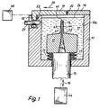
- Fig. 1 shows a section through a container 10, the cavity 10a largely with paint or coating agent 11, hereinafter referred to as "fluid", is filled.
- the container 10 which is approximately the shape of an elongated channel or one has elongated trough, there is an elongated member 12, one for the The coating process contains the necessary capillary gap 13.
- This one has usually a width in the range of 0.1 to 0.8 mm, and it is replaced by a vertically extending slot is formed in the component 12, which extends downwards expanded at 13a to the unimpeded inflow of the fluid 11 to To enable capillary gap 13.
- capillary gap 13 has an outlet opening 40, which could also be referred to as a nozzle and which are described below using the Fig. 7 is still shown in detail.
- this outlet opening 40 a Length in the range of e.g. Have 50 to 75 cm, but naturally also longer or shorter lengths are not excluded.
- the component 12 essentially has the shape of a cross section rectangular base body, which is inclined towards the top by two sloping, roof-like surfaces 41, 42 is limited, and two in the middle knife-like extensions 43, 44 protrude, each of which in the area of Nozzle 40 only has a width of about 0.1 ... 0.5 mm. These extensions 43, 44 Taper upwards and are extremely narrow there.
- the component 12 is connected to a rod 15 on its underside. This can via a device 44 shown only schematically in the direction of a Arrow 16 are moved vertically. This allows the component 12 to be vertical Direction.
- the cavity 10a of the container 10 is against the Carrying the rod 15 through its bottom in the manner shown a bellows 17 sealed, the cut on the right and left of the rod 15 can be seen.
- Suitable as device 44 is e.g. a hydraulic or pneumatic cylinder.
- the cavity 10a of the container 10 is at the top right (FIGS. 1 and 2) through a fixed plate 18 and top left through a displaceable angle profile 19th locked.
- the plate 18 is directly on the right side wall of the container 10 attached.
- the angle profile 19 is shown only schematically by means of a linear drive device 46 laterally in the direction of an arrow 20 (FIG. 1) displaceable. The guidance of this displacement movement can, for example, as shown, done via a guide pin 21 on the left Side wall of the container 10 is attached.
- the cavity 10a is closed by two elastomer profiles 22 and 23 sealed.
- the profile 22 is in a suitable groove in the end face of the plate 18th inserted and is through the end face of the angle profile 19 in Fig. 1st shown manner pressed.
- the sealing profile 23 is in a suitable groove inserted in the left side wall of the container 10 and is replaced by a vertically extending leg 19 'of the angle profile 19 pressed.
- the Contact pressure is applied by the device 46, which is the angular profile 19 moves.
- the plate 18 and the angle profile 19 with a suitable, solvent-resistant plastic, thickness e.g. 0.5 mm, which then takes over the sealing functions in the closed state.
- the component 12 with its capillary gap 13 is completely below the surface in FIG. 1 24 of the fluid 11 is shown immersed. This corresponds to a state at which is not lacquered, i.e. the outlet opening 40 of the component 12 is located below the surface 24 of the fluid 11.
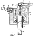
- Fig. 2 is the same cross section of the container 10 with all internals as shown in Fig. 1, but during a varnishing process.
- the one out Plate 18 and angle profile 19 is existing closure of the cavity 10a opened in that the angle profile 19 compared to the representation of FIG. 1 is shifted to the left in the direction of arrow 20.
- the component 12 with its capillary gap 13 was opened by a vertical movement of the rod 15 moved in the direction of an arrow 28 upwards.
- Fig. 2 is also a substrate 29 to be coated (in the form of a plate) during a coating process is shown.
- This substrate 29 is with uniform speed in the direction of an arrow 30 in very low Distance (e.g. 0.2 ... 0.5 mm) over the outlet opening 40 of the capillary gap 13 carried away.
- a distinction is made by capillary action and adhesion very uniform lacquer layer 31 on the underside 50 of the substrate 29. in the wet state, the thickness of the lacquer layer 31 is typically in the range from 5 to 50 ⁇ m.
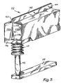
- Fig. 3 is a longitudinal section through part of the container 10 and the component 12 shown during a varnishing process.
- the component 12 is, as well as in the illustration in FIG. 2, moved upwards in the direction of arrow 28.
- A separates on the underside 50 of the substrate 29 to be coated uniform paint layer 31.
- the thickness of this layer 31 is Illustration depicted greatly exaggerated.
- FIG. 3 shows a left section 52 of the container 10 and the component 12, and the rod serving to drive it vertically 15.
- the rod 15 there is also one at the right end of the container 10 the rod 15 corresponding second rod, which is not shown in Fig. 3.
- a mirror plane is shown symbolically at 54.
- the entire length of the As already explained, component 12 can be, for example, 50 to 75 cm, the outer edge areas, as shown in Fig. 3, not for lacquering be used.
- an overflow pipe 32 is also shown in section.
- a pump 34 the level of the fluid 11 in the cavity 10a
- fluid begins to flow there. It passes through the overflow pipe 32 into an expansion tank 33, e.g. a Storage bottle, which contains e.g. 2.5 I of the fluid 11.
- the pump 34 is over a Tube 34 'is connected to the container 33 and sucks in this fluid 11. From the pump 34, the fluid 11 passes through a fine filter 35 and a line 35a back into the cavity 10a.
- Pump 34 and filter 35 are commercially available Components and therefore only shown schematically.
- a bellows 25 is also located within the cavity 10a upper end plate 56 is over a rod 57 which the bottom of the Penetrates container 10 with the piston 58 of a working cylinder 60th connected, which is actuated by means of a schematically illustrated device 62 can be.
- Piston 58 moved downward in the direction of an arrow 63, so moves the upper end plate 56 of the bellows 25 down, and the volume of the bellows 25 is reduced, with an opening 65 in the bottom of the Container 10 air can escape downwards. This causes the liquid level to drop 24 in the container 10 quickly. Conversely, the top end plate 56 moved upwards by means of the working cylinder 60, the liquid level rises 24 up to a maximum value, which is through the overflow pipe 32 is specified.
- the Liquid level 24 in the container 10 quickly according to the needs to be changed.
- the cover of the container 10th opened by the angle profile 19 through the device 46 to the left is moved. Then the knife-like extensions 43, 44 of the Component 12 up to a very short distance of e.g. 0.05 mm under the front edge of the substrate 29 to be coated. There when the pump 34 is switched off, the liquid level 24 drops slightly, e.g. by 0.1 to 0.5 mm, which does not bother.
- the minor Sinking is a consequence of those emerging from the fluid 11 knife-like extensions 43, 44 have only a small volume, which is very much here
- the movement of the component 12 creates a contact between the small fluid bead on the one hand, which from the immersion bath over the Exit opening 40 of the capillary gap 13 has remained, and on the other hand, the front lower edge of the substrate to be lacquered 29. After production this contact becomes the distance between the outlet opening 40 of the component 12 and the substrate 29 to be coated or coated again enlarged, e.g. to about 0.2 to 0.5 mm.
- This will start the capillary effect set the fluid 11 against gravity with uniform Speed transported through the capillary gap 13 upwards.
- the bellows 25 is rapidly reduced in size in the manner already described, e.g. within a second. As a result, the liquid level 24 decreases Cavity 10a rapidly. (The pump 34 stops during this.) In this way A negative pressure is created in the capillary gap 13, which corresponds to that in the capillary gap 13 contained fluid 11 sucks down. This causes fluid separation on the bottom of the plate 29 suddenly ended and an unwanted Bead formation on the (not shown) end edge of the substrate 29 is safe is prevented. Due to the extremely narrow shape of the knife-like extensions 43, 44 in the region of the nozzle 40 is achieved that on the end edge of the Do not form substrate beads 29 or the like.
- the component 12 is brought back down into the container 10 retracted, and the cover from plate 18 and 19 angle closed again to the interior of the container 10 to the outside complete airtight and evaporation of the fluid 11 in the cavity 10a to prevent.
- the pump 34 After closing the cover (by moving the angle profile 19 to the right) the pump 34 is switched on. That with the coating used fluid 11 is thus returned to the cavity 10a. As soon as the necessary filling level of the fluid 11 is reached, this begins again drain the overflow pipe 32 into the expansion tank 33. By the Circuit, the fluid 11 is filtered. The period during which the pump 34 is switched on, is generally only a few seconds. However, will found that the fluid 11 is contaminated, the pump 34 can also Let it run for a long time to clean the fluid using the filter 35. The Reservoir 33 needs to be replaced from time to time when the fluid in it is used up. A great advantage of the invention is the very economical consumption of fluid, e.g. only about 1 to 3 ml per plate to be coated 29. - As Storage container 33 can be used in the bottle in which the fluid 11 from is supplied to its manufacturer.
- part 12 could also be rotated about its longitudinal axis the position shown in FIG. 2 are brought into its submerged position.
- a vertical displacement of component 12 is currently preferred to undesirable, asymmetrical flow processes in the fluid during the Avoid painting if possible.
- a device according to the invention can be part of a larger one Form the coating system, e.g. is shown in PCT / DE93 / 00777. On The content of this PCT application is therefore to avoid lengths expressly referred.
- FIGS. 4 to 10 show a preferred embodiment of a Device 100 according to the invention. Same parts as in FIGS. 1 to 3 are identified by the same reference numerals as there, but by the number 100 increased, e.g. 113 instead of 13.
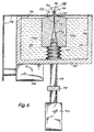
- Fig. 4 shows the device 100 in longitudinal section and in spatial representation Presentation.
- This device has an elongated, trough-like container 110, the bottom of which is designated 110 '.
- Its cavity 110a is as in FIG. 8 shown, filled with a fluid 111 up to the height of an overflow pipe 132.
- the fluid level is designated by 124 in FIG. 8.
- the container 110 there is an elongated component 112, which according to FIG. 5 two symmetrical halves 112a, 112b is composed by one Capillary gap 113 are separated from each other.
- This capillary gap 113 has according to Fig. 7 a width d1, depending on the fluid 111 used about 0.1 to 0.8 mm is.
- the capillary gap 113 widens to one in its lower region in cross section funnel-shaped extension 113 a, which in FIGS. 4, 5 and 6 is shown. It facilitates the supply of the fluid 111 to the capillary gap 113.
- the symmetrical halves are 112a, 112b are made wider in their central region in the vertical direction in order to to avoid deflection. They are fewer at both ends high, and there they are appropriately, e.g. by means of (not shown) Screws attached to mounting plates 170 and 171, which in turn with a cylindrical rod 115 and 115 'are connected. These poles penetrate the bottom 110 'of the container 110 and are at their lower Ends connected by a cross connector 172, and this is displaceable in the vertical direction by means of a device 144, whereby the Component 112 can be raised and lowered, as that with reference to FIGS. 1 and 2 for component 12 has already been described in detail.
- the device 144 can be any linear drive, e.g. a pneumatic cylinder or a electric linear actuator.
- the rods 115, 115 ' are shown in the figure by means of bellows 117, 117' Sealed in the same way as in FIGS. 1 to 3 using the bellows 17th already explained in detail.
- the halves 112a, 112b of the elongated body 112 each have a knife-like at their upper ends Extension 143 or 144, which projects substantially vertically upwards.
- Each of these Extensions 143, 144 end at the top in a narrow, horizontal in operation Area 177 or 178 (FIG. 7), in which the capillary gap 113 as opening 140 empties.
- This opening 140 and the surfaces 177, 178 surrounding it can also be called a nozzle.
- the surface 7 has a width d 2 , which is between 0.1 and 0.5 mm and is preferably 0.3 mm.
- the surface 178 has a width d 3 (FIG. 7) which is between 0.1 and 0.5 mm and is preferably 0.3 mm.
- the advantage of these narrow surfaces 177, 178 is that they largely prevent the formation of a fluid bead on the rear edge of a substrate 129 to be coated. Such a substrate is shown in FIG. 8. Its width W is smaller than the length of the component 12, ie only the middle length range W of the component 112 is used for a uniform coating. Discontinuities in the fluid layer (31 in FIGS. 1 to 3) could arise in the edge regions.
- a cover and sealing plate 118 As seen in FIG. 9, most of the top of the container 110 covered by a cover and sealing plate 118. This has one rectangular recess 118 ', and in this is a slidable Angle plate 119 fitted in there in the direction of an arrow 120 in is horizontally displaceable. If it is moved forward in FIG. 9, it thus forms an opening 119 'through which the knife-like extensions 143, 144 can be pushed up for a varnishing process. Becomes the angular plate 119 in Fig. 9 moved backward, it closes the Opening 119 'completely and sealingly. For this purpose, both plates 118 and 119 be coated with a solvent-resistant plastic (not shown), e.g. 0.5 mm thick and the desired sealing at the edges causes.
- a solvent-resistant plastic not shown
- Two linear plates serve to move the angle plate 119 horizontally Drive elements 146, 146 '(FIG. 10), which are actuated synchronously with one another, in order to achieve a uniform displacement of the angle plate 119.
- a bellows 125 is also located in the cavity 110a of the container 110, whose volume can be changed by means of an actuator 160. Is this volume changed by an actuating rod of the Bellows 125 is moved in the downward direction, this causes a rapid lowering of the fluid level 124 in the container 110, whereby the fluid in the Capillary gap 113 is sucked down and a coating process is ended. If the rod 157 is moved upward, the fluid level 124 rises rapidly.
- a downward-running pipe 180 is connected to the overflow pipe 132, through a lid 133 'into the interior of a storage bottle 133 for the fluid 111 leads. From this bottle 133 leads, also through the lid 133 ' Suction pipe 182 to a pump 134, which can only be operated when none Painting process takes place.
- This pump 134 pumps fluid towards one Arrow 183 (Fig. 8) to a fine filter 135, and from this through a line 135a back to the interior 110a of the container 110.
- the Pump 134 are operated. It then pumps fluid 111 out of the reservoir 133 through the fine filter 135 into the cavity 110a of the container 110 and fills this up to the height of the overflow pipe 132 (Fig. 8). (At a Coating process, the fluid level 124 drops slightly because for the A small amount of fluid is consumed.)
- the cover of the container 110 is opened by the angle plate 119 through the two devices 146, 146 'in the opening direction is moved. Then the knife-like extensions 143, 144 of the component 112 by means of the drive 144 up to one short distance from e.g. 0.05 mm below the front edge of the area to be coated Moved up substrate 129. This creates a contact between the small fluid bead, on the one hand, which is transferred from the fluid 111 in the container 110 of the outlet opening 140 of the capillary gap 113, and on the other hand the front lower edge of the substrate 129 to be coated.
- this contact becomes the distance between the outlet opening 140 of the Component 112 and the substrate 129 to be coated or coated again slightly enlarged, e.g. to about 0.2 to 0.5 mm.
- the capillary effect started the fluid 111 from the container 110 against gravity up at a uniform speed through the capillary gap 113 transported.
- the substrate 129 is moving at a uniform speed horizontally set in motion, as described in detail in Fig. 2.
- the bellows 125 is rapidly reduced in size in the manner already described, e.g. within a second. As a result, the liquid level 124 drops Cavity 110a rapidly. (The pump 134 is stopped.) In this way A negative pressure is created in the capillary gap 113, which fluid 111 located there sucks down. This causes fluid separation on the bottom of substrate 129 suddenly terminates and undesirable bead formation occurs the (not shown) end edge of the substrate 129 is surely prevented. Due to the extremely narrow shape of the knife-like extensions 143, 144 in The area of the opening 140 is reached at the end edge of the substrate 129 do not form paint beads or the like.
- the component 112 is then lowered again by means of the drive 144 returned to the container 110 where it is completely in the fluid 111 is submerged, and the opening 119 'is through the angle plate 119 again hermetically sealed to the interior of the container 110 to the outside seal and thus evaporation of the fluid 111 in the cavity 110a prevent.
- the pump 134 is switched on, and thereby the fluid 111 consumed in a coating process returned to the cavity 110a.
- the fluid 111 begins again through the overflow pipe 132 into the storage and To drain expansion tank 133.
- the fluid becomes 111 through the circuit filtered through the fine filter 135.
- the pump becomes common for this purpose only switched on for a few seconds, but can be used to clean the Fluids 111 can also be switched on for longer.
- the reservoir 133 will replaced with a new bottle when the fluid 111 in it is used up. To do this, a new bottle 133 is attached to the bottom fixed cover 133 'screwed.
- the closure of the container 110 can naturally are accomplished in various ways, e.g. also by putting on a Cover from above.
- the substrate 129 can be viewed from above bring the opening 140 of the component 112 closer, instead of the other way round this opening 140 lead to the underside of the substrate 129.
- a pump may be provided which rapidly draws fluid 111 from the container 110 to the fluid level 124 quickly lower
- this pump simply as a cavity one Working cylinder can be formed. This would be analogous to the process of how the liquid to be injected into an injection syringe before an injection sucks. In both cases (pump or cylinder) the liquid can then pumped back into the container 110, e.g. by Reversal of the delivery direction of this pump (not shown).
Description
- Fig. 1
- einen Querschnitt durch eine erfindungsgemäße Vorrichtung, bei der sich das einen Kapillarspalt bildende Bauteil in einem untergetauchten Zustand befindet,
- Fig. 2
- einen Querschnitt durch die Vorrichtung der Fig. 1, bei der das den Kapillarspalt bildende Bauteil während eines Belackungsvorganges aus dem Fluid im Behälter herausgetaucht ist, gesehen längs der Linie II-II der Fig. 3,
- Fig. 3
- einen Längsschnitt durch einen Teil einer erfindungsgemäßen Vorrichtung mit ausgetauchtem Kapillarspaltbauteil, während eines Belackungsvorganges,
- Fig. 4
- eine teilweise im Schnitt dargestellte, raumbildliche Darstellung eines bevorzugten Ausführungsbeispiels einer erfindungsgemäßen Vorrichtung,
- Fig. 5
- eine Einzelheit der Fig. 4, ebenfalls in raumbildlicher Darstellung,
- Fig. 6
- einen Schnitt, gesehen längs der Linie VI-VI der Fig. 8, in einem gegenüber Fig. 6 vergrößerten Maßstab,
- Fig. 7
- eine raumbildliche Darstellung der Einzelheit VII der Fig. 6,
- Fig. 8
- einen Längsschnitt durch die in Fig. 4 dargestellte Vorrichtung,
- Fig. 9
- eine raumbildliche Darstellung der in Fig. 4 dargestellten Vorrichtung, wobei sich der Kapillarspalt in seiner Arbeitsstellung befindet, gesehen von oben, und
- Fig. 10
- eine raumbildliche Darstellung analog Fig. 9, aber gesehen von unten.
Claims (8)
- Verfahren zum Belacken oder Beschichten eines Substrats mittels eines einen Kapillarspalt aufweisenden Bauteils und eines über diesen Kapillarspalt zugeführten Fluids, mit folgenden Schritten:Das Fluid wird dem Substrat über den Kapillarspalt des Bauteils von unten aus einem das Fluid enthaltenden Behälter durch Kapillarwirkung zugeführt;am Ende der Belackung oder Beschichtung wird das Niveau (24; 124) des Fluids im Behälter (10; 110) abgesenkt und dadurch im Kapillarspalt des Bauteils ein Unterdruck erzeugt, der das im Kapillarspalt des Bauteils enthaltende Fluid nach unten saugt, um den Vorgang der Belackung oder Beschichtung zu unterbrechen.
- Vorrichtung zur Belackung oder Beschichtung eines Substrats (29; 129) mittels eines einen Kapillarspalt (13; 113) aufweisenden Bauteils (12; 112), zur Durchführung eines Verfahrens nach Anspruch 1,
mit einem Lack oder Beschichtungsflüssigkeit - im folgenden Fluid (11; 111) genannt - enthaltenden Behälter (10; 110), in welchem das Bauteil (12; 112) so angeordnet ist, dass der Kapillarspalt (13; 113) des Bauteils (12; 112) mit dem Fluid (11; 111) im Behälter in Verbindung steht und dieses Fluid dem Kapillarspalt (13; 113) des Bauteils (12; 112) von unten aus dem Behälter (10; 110) durch Kapillarwirkung zuführbar ist,
und mit Mitteln (25; 125) zur Absenkung des Niveaus (24; 124) des Fluids im Behälter (10; 110) zur Erzeugung eines Unterdrucks im Kapillarspalt (13; 113) des Bauteils (12; 112), um das im Kapillarspalt des Bauteils enthaltene Fluid (11; 111) nach unten zu saugen, um den Vorgang der Belackung oder Beschichtung zu unterbrechen. - Vorrichtung nach Anspruch 2, bei welcher in dem im Behälter (10; 110) befindlichen Fluid (11; 111) ein Bauteil (25; 125) angeordnet ist, dessen Volumen veränderbar ist, um das Niveau (24; 124) des Fluids im Behälter (10; 110) durch Reduzierung dieses Volumens absenken zu können.
- Vorrichtung nach Anspruch 3, bei welcher das Bauteil als Balg (25; 125) ausgebildet ist.
- Vorrichtung nach Anspruch 4, bei welcher das Volumen des Balgs (25; 125) durch einen Linearantrieb (60; 160) veränderbar ist.
- Vorrichtung nach einem der Ansprüche 2 bis 5, bei welcher die Austrittsöffnung (40; 140) des Kapillarspalts (13; 113) durch eine in Höhenrichtung erfolgende Bewegung vollständig in das Fluid (11; 111) eintauchbar ist (Fig. 1).
- Vorrichtung nach einem der Ansprüche 2 bis 6, bei welcher die Austrittsöffnung (40; 140) des Kapillarspalts (13; 113) durch eine in Höhenrichtung erfolgende Bewegung an die Unterseite (50) eines Substrats (29; 129) heranführbar ist, oder umgekehrt.
- Vorrichtung nach einem der Ansprüche 2 bis 7, bei welcher eine Filtriervorrichtung (35; 135) und eine Pumpe (34; 134) vorgesehen sind, um im Behälter (10; 110) befindliches Fluid (11; 111) im Umlauf zu filtrieren.
Applications Claiming Priority (4)
| Application Number | Priority Date | Filing Date | Title |
|---|---|---|---|
| DE4445985 | 1994-12-22 | ||
| DE4445985A DE4445985A1 (de) | 1994-12-22 | 1994-12-22 | Verfahren und Vorrichtung zur Belackung oder Beschichtung eines Substrats |
| EP99120202A EP0972575B1 (de) | 1994-12-22 | 1995-03-11 | Vorrichtung zur Belackung oder Beschichtung eines Substrats |
| EP95913085A EP0799096B1 (de) | 1994-12-22 | 1995-03-11 | Verfahren und vorrichtung zur belackung oder beschichtung eines substrats |
Related Parent Applications (1)
| Application Number | Title | Priority Date | Filing Date |
|---|---|---|---|
| EP99120202A Division EP0972575B1 (de) | 1994-12-22 | 1995-03-11 | Vorrichtung zur Belackung oder Beschichtung eines Substrats |
Publications (3)
| Publication Number | Publication Date |
|---|---|
| EP1210984A2 EP1210984A2 (de) | 2002-06-05 |
| EP1210984A3 EP1210984A3 (de) | 2002-08-21 |
| EP1210984B1 true EP1210984B1 (de) | 2004-06-16 |
Family
ID=6536721
Family Applications (3)
| Application Number | Title | Priority Date | Filing Date |
|---|---|---|---|
| EP99120202A Expired - Lifetime EP0972575B1 (de) | 1994-12-22 | 1995-03-11 | Vorrichtung zur Belackung oder Beschichtung eines Substrats |
| EP02003487A Expired - Lifetime EP1210984B1 (de) | 1994-12-22 | 1995-03-11 | Verfahren und Vorrichtung zur Belackung oder Beschichtung eines Substrats |
| EP95913085A Expired - Lifetime EP0799096B1 (de) | 1994-12-22 | 1995-03-11 | Verfahren und vorrichtung zur belackung oder beschichtung eines substrats |
Family Applications Before (1)
| Application Number | Title | Priority Date | Filing Date |
|---|---|---|---|
| EP99120202A Expired - Lifetime EP0972575B1 (de) | 1994-12-22 | 1995-03-11 | Vorrichtung zur Belackung oder Beschichtung eines Substrats |
Family Applications After (1)
| Application Number | Title | Priority Date | Filing Date |
|---|---|---|---|
| EP95913085A Expired - Lifetime EP0799096B1 (de) | 1994-12-22 | 1995-03-11 | Verfahren und vorrichtung zur belackung oder beschichtung eines substrats |
Country Status (10)
| Country | Link |
|---|---|
| EP (3) | EP0972575B1 (de) |
| KR (1) | KR100209117B1 (de) |
| CN (1) | CN1087198C (de) |
| AT (3) | ATE202954T1 (de) |
| AU (1) | AU701991B2 (de) |
| DE (3) | DE59510480D1 (de) |
| DK (2) | DK0972575T3 (de) |
| ES (2) | ES2189333T3 (de) |
| GR (1) | GR3036846T3 (de) |
| TW (1) | TW397709B (de) |
Families Citing this family (12)
| Publication number | Priority date | Publication date | Assignee | Title |
|---|---|---|---|---|
| JP4481688B2 (ja) * | 2003-04-10 | 2010-06-16 | Hoya株式会社 | 基板処理装置,塗布装置、塗布方法、及び、フォトマスクの製造方法 |
| JP2004335728A (ja) * | 2003-05-07 | 2004-11-25 | Hoya Corp | 基板塗布装置及び基板塗布方法 |
| JP4169719B2 (ja) * | 2004-03-30 | 2008-10-22 | Hoya株式会社 | レジスト膜付基板の製造方法 |
| JP2008168254A (ja) * | 2007-01-15 | 2008-07-24 | Hoya Corp | 塗布方法及び塗布装置、並びにフォトマスクブランクの製造方法 |
| JP5086708B2 (ja) * | 2007-06-29 | 2012-11-28 | Hoya株式会社 | マスクブランクの製造方法及び塗布装置 |
| TWI458562B (zh) * | 2009-11-27 | 2014-11-01 | Hon Hai Prec Ind Co Ltd | 液體回收方法 |
| DE102011081980B4 (de) * | 2011-09-01 | 2023-07-06 | Gebr. Schmid Gmbh & Co. | Vorrichtung zum Benetzen von flachen Substraten und Anlage mit einer solchen Vorrichtung |
| KR20140069677A (ko) * | 2012-11-29 | 2014-06-10 | 삼성디스플레이 주식회사 | 기판 프린팅 장치 및 기판 프린팅 방법 |
| CN105080789B (zh) * | 2015-08-10 | 2017-11-07 | 深圳市华星光电技术有限公司 | 涂布装置及涂布器 |
| CN109594056B (zh) * | 2018-12-18 | 2021-02-12 | 国家电投集团科学技术研究院有限公司 | 基板及制备方法、封孔系统、包壳管 |
| CN111804504B (zh) * | 2020-05-29 | 2021-12-31 | 中国船舶重工集团公司第七0七研究所 | 一种基于毛细作用的光纤环圈制作用在线施胶装置 |
| CN112024283A (zh) * | 2020-08-20 | 2020-12-04 | 深圳市裕展精密科技有限公司 | 导入装置、导入方法及产品 |
Family Cites Families (6)
| Publication number | Priority date | Publication date | Assignee | Title |
|---|---|---|---|---|
| US2046596A (en) * | 1932-01-13 | 1936-07-07 | Patent Button Co | Apparatus for uniformly coating flat surfaces |
| DE2204625A1 (de) * | 1972-02-01 | 1973-08-09 | Schildkroet Spielwaren | Benetzungsvorrichtung |
| DE9103494U1 (de) | 1991-03-21 | 1992-07-16 | Hamatech Halbleiter-Maschinenbau Und Technologie Gmbh, 7137 Sternenfels, De | |
| DE9300777U1 (de) | 1993-01-21 | 1994-05-19 | Siemens Ag | Elektrische Durchführung mit Spannungsabgriff |
| CA2157033C (en) * | 1993-05-05 | 2003-06-17 | Eberhard Muhlfriedel | Device for lacquering or coating of plates or disks |
| EP0654306B1 (de) * | 1993-05-27 | 2001-08-16 | Dai Nippon Printing Co., Ltd. | Verfahren und vorrichtung zum flüssigkeitsauftrag |
-
1995
- 1995-03-11 ES ES99120202T patent/ES2189333T3/es not_active Expired - Lifetime
- 1995-03-11 EP EP99120202A patent/EP0972575B1/de not_active Expired - Lifetime
- 1995-03-11 AT AT95913085T patent/ATE202954T1/de not_active IP Right Cessation
- 1995-03-11 DE DE59510480T patent/DE59510480D1/de not_active Expired - Lifetime
- 1995-03-11 AT AT99120202T patent/ATE228395T1/de not_active IP Right Cessation
- 1995-03-11 AU AU20686/95A patent/AU701991B2/en not_active Ceased
- 1995-03-11 DK DK99120202T patent/DK0972575T3/da active
- 1995-03-11 DE DE59510915T patent/DE59510915D1/de not_active Expired - Lifetime
- 1995-03-11 ES ES95913085T patent/ES2161285T3/es not_active Expired - Lifetime
- 1995-03-11 KR KR1019960704172A patent/KR100209117B1/ko not_active IP Right Cessation
- 1995-03-11 EP EP02003487A patent/EP1210984B1/de not_active Expired - Lifetime
- 1995-03-11 AT AT02003487T patent/ATE269168T1/de not_active IP Right Cessation
- 1995-03-11 EP EP95913085A patent/EP0799096B1/de not_active Expired - Lifetime
- 1995-03-11 DK DK95913085T patent/DK0799096T3/da active
- 1995-03-11 DE DE59509410T patent/DE59509410D1/de not_active Expired - Lifetime
- 1995-03-11 CN CN95197003A patent/CN1087198C/zh not_active Expired - Lifetime
- 1995-06-09 TW TW084105865A patent/TW397709B/zh not_active IP Right Cessation
-
2001
- 2001-10-09 GR GR20010401710T patent/GR3036846T3/el not_active IP Right Cessation
Also Published As
| Publication number | Publication date |
|---|---|
| EP0972575A2 (de) | 2000-01-19 |
| EP0972575A3 (de) | 2000-11-15 |
| CN1087198C (zh) | 2002-07-10 |
| CN1172443A (zh) | 1998-02-04 |
| ATE228395T1 (de) | 2002-12-15 |
| DK0972575T3 (da) | 2003-03-24 |
| ES2161285T3 (es) | 2001-12-01 |
| ATE202954T1 (de) | 2001-07-15 |
| EP0799096B1 (de) | 2001-07-11 |
| EP0799096A1 (de) | 1997-10-08 |
| TW397709B (en) | 2000-07-11 |
| DE59510480D1 (de) | 2003-01-09 |
| DE59509410D1 (de) | 2001-08-16 |
| EP1210984A2 (de) | 2002-06-05 |
| DK0799096T3 (da) | 2001-11-05 |
| DE59510915D1 (de) | 2004-07-22 |
| EP1210984A3 (de) | 2002-08-21 |
| ES2189333T3 (es) | 2003-07-01 |
| AU701991B2 (en) | 1999-02-11 |
| EP0972575B1 (de) | 2002-11-27 |
| ATE269168T1 (de) | 2004-07-15 |
| GR3036846T3 (en) | 2002-01-31 |
| KR100209117B1 (ko) | 1999-07-15 |
| AU2068695A (en) | 1996-07-10 |
Similar Documents
| Publication | Publication Date | Title |
|---|---|---|
| WO1996019295A1 (de) | Verfahren und vorrichtung zur belackung oder beschichtung eines substrats | |
| EP1210984B1 (de) | Verfahren und Vorrichtung zur Belackung oder Beschichtung eines Substrats | |
| DE3024823C2 (de) | ||
| DE3026859A1 (de) | Vorrichtung fuer das aufbringen von photolack auf siliziumwafer | |
| DE3810920A1 (de) | Fluessigkeitsstrahl-aufzeichnungsvorrichtung und verfahren fuer eine fluessigkeitsabweisebehandlung derselben | |
| DE1652329A1 (de) | Verfahren und Vorrichtung zur Aufbringung einer Fluessigkeit auf einer Oberflaeche | |
| DE2409618A1 (de) | Spruehkopf und spruehvorrichtung | |
| DE2617767C3 (de) | Verfahren und Vorrichtung zum gleichmäßigen Beschichten von Körpern | |
| EP0701487B1 (de) | Vorrichtung zur belackung oder beschichtung von platten oder scheiben | |
| DE4423204A1 (de) | Vorrichtung zum Beschichten von elektronischen Bauteilen | |
| DE2330135A1 (de) | Verfahren zur absaugung einer fluessigkeit und absaugvorrichtung zur durchfuehrung des verfahrens | |
| DE4300012C2 (de) | Verfahren und Vorrichtung zur selektiven Lackierung einer mit Bauteilen unterschiedlicher Höhe bestückten Leiterplatte | |
| DE102005008741B4 (de) | Verfahren und Vorrichtung zum selektiven Befüllen von regelmässig angeordneten wabenartigen Strukturen | |
| DE3410305C1 (de) | Membranpumpe | |
| DE4427676C1 (de) | Verfahren und Vorrichtung zum Zuführen eines Flüssigkristalls in eine Flüssigkristallzelle | |
| EP0498351B1 (de) | Beschichtungseinrichtung | |
| EP3505232A1 (de) | Vorrichtung zum mischen und/oder dosieren von flüssigen beschichtungsstoffen, beschichtungsanlage mit einer solchen vorrichtung und verfahren zum färben optischer gläser | |
| DE4021621A1 (de) | Verfahren und vorrichtung zur belackung einer oberflaeche mit schutzlack oder fotolack | |
| EP3235574B1 (de) | Derivatisierungsgerät und -verfahren | |
| DE4032833B4 (de) | Gieß-Auftragvorrichtung für hochviskose Produkte | |
| EP0711108B1 (de) | Vorrichtung zur belackung von substraten in der halbleiterfertigung | |
| DE3620676C2 (de) | ||
| DE10136571A1 (de) | Verfahren zum partiellen Schutzbeschichten von Leiterplatten und Lackieranlage zur Durchführung des Verfahrens | |
| DE2162267B2 (de) | Verfahren und Vorrichtung zum Überziehen bestimmter Flachenteile eines Gegenstandes mit einer Flüssigkeit | |
| DE4300632A1 (de) | Verfahren und Vorrichtung zur Bearbeitung von plattenförmigen Werkstücken |
Legal Events
| Date | Code | Title | Description |
|---|---|---|---|
| PUAI | Public reference made under article 153(3) epc to a published international application that has entered the european phase |
Free format text: ORIGINAL CODE: 0009012 |
|
| 17P | Request for examination filed |
Effective date: 20020215 |
|
| AC | Divisional application: reference to earlier application |
Ref document number: 799096 Country of ref document: EP Ref document number: 972575 Country of ref document: EP |
|
| AK | Designated contracting states |
Kind code of ref document: A2 Designated state(s): AT BE CH DE DK ES FR GB GR IE IT LI LU MC NL PT SE |
|
| PUAL | Search report despatched |
Free format text: ORIGINAL CODE: 0009013 |
|
| AK | Designated contracting states |
Kind code of ref document: A3 Designated state(s): AT BE CH DE DK ES FR GB GR IE IT LI LU MC NL PT SE |
|
| RIN1 | Information on inventor provided before grant (corrected) |
Inventor name: APPICH, KARL Inventor name: STUMMER, MANFRED |
|
| AKX | Designation fees paid |
Designated state(s): AT BE CH DE DK ES FR GB GR IE IT LI LU MC NL PT SE |
|
| 17Q | First examination report despatched |
Effective date: 20030710 |
|
| GRAP | Despatch of communication of intention to grant a patent |
Free format text: ORIGINAL CODE: EPIDOSNIGR1 |
|
| GRAS | Grant fee paid |
Free format text: ORIGINAL CODE: EPIDOSNIGR3 |
|
| GRAA | (expected) grant |
Free format text: ORIGINAL CODE: 0009210 |
|
| AC | Divisional application: reference to earlier application |
Ref document number: 0799096 Country of ref document: EP Kind code of ref document: P Ref document number: 0972575 Country of ref document: EP Kind code of ref document: P |
|
| AK | Designated contracting states |
Kind code of ref document: B1 Designated state(s): AT BE CH DE DK ES FR GB GR IE IT LI LU MC NL PT SE |
|
| PG25 | Lapsed in a contracting state [announced via postgrant information from national office to epo] |
Ref country code: ES Free format text: LAPSE BECAUSE OF FAILURE TO SUBMIT A TRANSLATION OF THE DESCRIPTION OR TO PAY THE FEE WITHIN THE PRESCRIBED TIME-LIMIT Effective date: 20040616 |
|
| REG | Reference to a national code |
Ref country code: GB Ref legal event code: FG4D Free format text: NOT ENGLISH |
|
| REG | Reference to a national code |
Ref country code: CH Ref legal event code: EP |
|
| REF | Corresponds to: |
Ref document number: 59510915 Country of ref document: DE Date of ref document: 20040722 Kind code of ref document: P |
|
| REG | Reference to a national code |
Ref country code: IE Ref legal event code: FG4D Free format text: GERMAN |
|
| GBT | Gb: translation of ep patent filed (gb section 77(6)(a)/1977) |
Effective date: 20040825 |
|
| PG25 | Lapsed in a contracting state [announced via postgrant information from national office to epo] |
Ref country code: GR Free format text: LAPSE BECAUSE OF FAILURE TO SUBMIT A TRANSLATION OF THE DESCRIPTION OR TO PAY THE FEE WITHIN THE PRESCRIBED TIME-LIMIT Effective date: 20040916 Ref country code: SE Free format text: LAPSE BECAUSE OF FAILURE TO SUBMIT A TRANSLATION OF THE DESCRIPTION OR TO PAY THE FEE WITHIN THE PRESCRIBED TIME-LIMIT Effective date: 20040916 Ref country code: DK Free format text: LAPSE BECAUSE OF FAILURE TO SUBMIT A TRANSLATION OF THE DESCRIPTION OR TO PAY THE FEE WITHIN THE PRESCRIBED TIME-LIMIT Effective date: 20040916 |
|
| ET | Fr: translation filed | ||
| PG25 | Lapsed in a contracting state [announced via postgrant information from national office to epo] |
Ref country code: AT Free format text: LAPSE BECAUSE OF NON-PAYMENT OF DUE FEES Effective date: 20050311 Ref country code: LU Free format text: LAPSE BECAUSE OF NON-PAYMENT OF DUE FEES Effective date: 20050311 |
|
| PG25 | Lapsed in a contracting state [announced via postgrant information from national office to epo] |
Ref country code: CH Free format text: LAPSE BECAUSE OF NON-PAYMENT OF DUE FEES Effective date: 20050331 Ref country code: BE Free format text: LAPSE BECAUSE OF NON-PAYMENT OF DUE FEES Effective date: 20050331 Ref country code: MC Free format text: LAPSE BECAUSE OF NON-PAYMENT OF DUE FEES Effective date: 20050331 Ref country code: LI Free format text: LAPSE BECAUSE OF NON-PAYMENT OF DUE FEES Effective date: 20050331 |
|
| PLBE | No opposition filed within time limit |
Free format text: ORIGINAL CODE: 0009261 |
|
| STAA | Information on the status of an ep patent application or granted ep patent |
Free format text: STATUS: NO OPPOSITION FILED WITHIN TIME LIMIT |
|
| 26N | No opposition filed |
Effective date: 20050317 |
|
| BERE | Be: lapsed |
Owner name: *STEAG HAMATECH A.G. Effective date: 20050331 |
|
| REG | Reference to a national code |
Ref country code: CH Ref legal event code: PL |
|
| BERE | Be: lapsed |
Owner name: *STEAG HAMATECH A.G. Effective date: 20050331 |
|
| PG25 | Lapsed in a contracting state [announced via postgrant information from national office to epo] |
Ref country code: PT Free format text: LAPSE BECAUSE OF NON-PAYMENT OF DUE FEES Effective date: 20041116 |
|
| PGFP | Annual fee paid to national office [announced via postgrant information from national office to epo] |
Ref country code: GB Payment date: 20100322 Year of fee payment: 16 |
|
| REG | Reference to a national code |
Ref country code: GB Ref legal event code: 732E Free format text: REGISTERED BETWEEN 20101216 AND 20101222 |
|
| REG | Reference to a national code |
Ref country code: GB Ref legal event code: 732E Free format text: REGISTERED BETWEEN 20101230 AND 20110105 |
|
| PGFP | Annual fee paid to national office [announced via postgrant information from national office to epo] |
Ref country code: NL Payment date: 20110316 Year of fee payment: 17 |
|
| REG | Reference to a national code |
Ref country code: FR Ref legal event code: CD Ref country code: FR Ref legal event code: TP Ref country code: FR Ref legal event code: CA |
|
| GBPC | Gb: european patent ceased through non-payment of renewal fee |
Effective date: 20110311 |
|
| PG25 | Lapsed in a contracting state [announced via postgrant information from national office to epo] |
Ref country code: GB Free format text: LAPSE BECAUSE OF NON-PAYMENT OF DUE FEES Effective date: 20110311 |
|
| PGFP | Annual fee paid to national office [announced via postgrant information from national office to epo] |
Ref country code: IT Payment date: 20120322 Year of fee payment: 18 |
|
| REG | Reference to a national code |
Ref country code: NL Ref legal event code: V1 Effective date: 20121001 |
|
| PG25 | Lapsed in a contracting state [announced via postgrant information from national office to epo] |
Ref country code: NL Free format text: LAPSE BECAUSE OF NON-PAYMENT OF DUE FEES Effective date: 20121001 |
|
| PGFP | Annual fee paid to national office [announced via postgrant information from national office to epo] |
Ref country code: FR Payment date: 20130408 Year of fee payment: 19 Ref country code: IE Payment date: 20130322 Year of fee payment: 19 |
|
| PGFP | Annual fee paid to national office [announced via postgrant information from national office to epo] |
Ref country code: DE Payment date: 20140219 Year of fee payment: 20 |
|
| REG | Reference to a national code |
Ref country code: FR Ref legal event code: ST Effective date: 20141128 |
|
| REG | Reference to a national code |
Ref country code: IE Ref legal event code: MM4A |
|
| PG25 | Lapsed in a contracting state [announced via postgrant information from national office to epo] |
Ref country code: FR Free format text: LAPSE BECAUSE OF NON-PAYMENT OF DUE FEES Effective date: 20140331 Ref country code: IE Free format text: LAPSE BECAUSE OF NON-PAYMENT OF DUE FEES Effective date: 20140311 |
|
| REG | Reference to a national code |
Ref country code: DE Ref legal event code: R071 Ref document number: 59510915 Country of ref document: DE |
|
| PG25 | Lapsed in a contracting state [announced via postgrant information from national office to epo] |
Ref country code: IT Free format text: LAPSE BECAUSE OF NON-PAYMENT OF DUE FEES Effective date: 20140311 |