EP1207032A1 - Verfahren und Vorrichtung zum Steuern einer Spritzgiessmaschine geeignet zum Reduzieren der Gewichtsänderungen von Formkörpern - Google Patents
Verfahren und Vorrichtung zum Steuern einer Spritzgiessmaschine geeignet zum Reduzieren der Gewichtsänderungen von Formkörpern Download PDFInfo
- Publication number
- EP1207032A1 EP1207032A1 EP01127324A EP01127324A EP1207032A1 EP 1207032 A1 EP1207032 A1 EP 1207032A1 EP 01127324 A EP01127324 A EP 01127324A EP 01127324 A EP01127324 A EP 01127324A EP 1207032 A1 EP1207032 A1 EP 1207032A1
- Authority
- EP
- European Patent Office
- Prior art keywords
- screw
- synchronization ratio
- heating cylinder
- flight
- backward
- Prior art date
- Legal status (The legal status is an assumption and is not a legal conclusion. Google has not performed a legal analysis and makes no representation as to the accuracy of the status listed.)
- Granted
Links
- 238000000034 method Methods 0.000 title claims description 122
- 238000001746 injection moulding Methods 0.000 title claims description 47
- 239000011347 resin Substances 0.000 claims abstract description 78
- 229920005989 resin Polymers 0.000 claims abstract description 78
- 238000010438 heat treatment Methods 0.000 claims abstract description 64
- 230000033001 locomotion Effects 0.000 claims abstract description 28
- 238000002347 injection Methods 0.000 claims description 23
- 239000007924 injection Substances 0.000 claims description 23
- 230000001419 dependent effect Effects 0.000 claims description 2
- 238000005429 filling process Methods 0.000 description 3
- 238000010586 diagram Methods 0.000 description 2
- 238000009826 distribution Methods 0.000 description 2
- 238000002844 melting Methods 0.000 description 2
- 230000008018 melting Effects 0.000 description 2
- 238000000465 moulding Methods 0.000 description 2
- 239000000047 product Substances 0.000 description 2
- 239000012265 solid product Substances 0.000 description 2
- 230000000694 effects Effects 0.000 description 1
- 230000010006 flight Effects 0.000 description 1
- 239000007789 gas Substances 0.000 description 1
- 239000000155 melt Substances 0.000 description 1
- 239000002184 metal Substances 0.000 description 1
- 239000002245 particle Substances 0.000 description 1
- 238000003825 pressing Methods 0.000 description 1
- 238000010008 shearing Methods 0.000 description 1
- 239000007787 solid Substances 0.000 description 1
- 238000009827 uniform distribution Methods 0.000 description 1
- XLYOFNOQVPJJNP-UHFFFAOYSA-N water Substances O XLYOFNOQVPJJNP-UHFFFAOYSA-N 0.000 description 1
Images


Classifications
-
- B—PERFORMING OPERATIONS; TRANSPORTING
- B29—WORKING OF PLASTICS; WORKING OF SUBSTANCES IN A PLASTIC STATE IN GENERAL
- B29C—SHAPING OR JOINING OF PLASTICS; SHAPING OF MATERIAL IN A PLASTIC STATE, NOT OTHERWISE PROVIDED FOR; AFTER-TREATMENT OF THE SHAPED PRODUCTS, e.g. REPAIRING
- B29C45/00—Injection moulding, i.e. forcing the required volume of moulding material through a nozzle into a closed mould; Apparatus therefor
- B29C45/17—Component parts, details or accessories; Auxiliary operations
- B29C45/76—Measuring, controlling or regulating
-
- B—PERFORMING OPERATIONS; TRANSPORTING
- B29—WORKING OF PLASTICS; WORKING OF SUBSTANCES IN A PLASTIC STATE IN GENERAL
- B29C—SHAPING OR JOINING OF PLASTICS; SHAPING OF MATERIAL IN A PLASTIC STATE, NOT OTHERWISE PROVIDED FOR; AFTER-TREATMENT OF THE SHAPED PRODUCTS, e.g. REPAIRING
- B29C45/00—Injection moulding, i.e. forcing the required volume of moulding material through a nozzle into a closed mould; Apparatus therefor
- B29C45/17—Component parts, details or accessories; Auxiliary operations
- B29C2045/1784—Component parts, details or accessories not otherwise provided for; Auxiliary operations not otherwise provided for
- B29C2045/1792—Machine parts driven by an electric motor, e.g. electric servomotor
-
- B—PERFORMING OPERATIONS; TRANSPORTING
- B29—WORKING OF PLASTICS; WORKING OF SUBSTANCES IN A PLASTIC STATE IN GENERAL
- B29K—INDEXING SCHEME ASSOCIATED WITH SUBCLASSES B29B, B29C OR B29D, RELATING TO MOULDING MATERIALS OR TO MATERIALS FOR MOULDS, REINFORCEMENTS, FILLERS OR PREFORMED PARTS, e.g. INSERTS
- B29K2995/00—Properties of moulding materials, reinforcements, fillers, preformed parts or moulds
- B29K2995/0037—Other properties
- B29K2995/0063—Density
Definitions
- the present invention relates to a method for controlling a motor-driven injection molding machine.
- An injection molding machine comprises a screw located within a heating cylinder.
- An injection shaft is directly connected to the rear end portion of the screw.
- the injection shaft is rotatably supported by a pressure plate through some bearings.
- the injection shaft is driven in an axial direction by an injection servomotor that is supported on the pressure plate.
- the pressure plate moves forwards and backwards along guide bars in response to the operation of the injection servomotor through a ball screw.
- the screw is rotated by a measuring servomotor for screw rotation in a plasticization/measuring process.
- a resin is fed from a hopper to a rear portion of the screw in the heating cylinder. Rotation of the screw melts and advances the resin and thus a certain measured amount of resin is fed to a nose portion of the heating cylinder. During this time, the screw is driven backwards due to a back pressure of the molten resin trapped in the nose portion of the heating cylinder.
- the above-mentioned back pressure of the molten resin is detected by using a load cell and is controlled with a feedback control loop, as will be described in more detail below.
- the pressure plate is advanced by means of driving the injection servomotor.
- a nose portion of the screw serves as a piston to fill a cavity of a mold with the molten resin.
- the resin within the cavity of the mold is allowed to cool under a predetermined pressure.
- This process is referred to as a dwelling process or a hold pressure process.
- the pressure of the resin is controlled in a feedback control loop as in the above-mentioned back pressure control.
- the filling process and the hold pressure process continued from the filling process will collectively be called an injecting process.
- an injection device returns to the plasticization/measuring process after the completion of the hold pressure process.
- an eject operation is carried out for ejecting a solid product out of the mold in parallel with the piasticization/measuring process.
- the eject operation involves the opening of the mold to remove the solid product from the mold by means of an ejector mechanism and then closing the mold for the injecting process.
- a screw 20 comprises a feed section 20-1, a compressing section 20-2, a measuring section 20-3, and a head section 20-4.
- the feed section 20-1 feeds the resin supplied from a hopper forward in a solid or partly melted state.
- the resin is heated to close to melting point at the feed section 20-1. Therefore, in general, the diameter of the rod-shaped body of the screw 20 shown in Fig. 1 B, which forms a spiral thereon, is substantially constant.
- the spiral is typically called a flight.
- the measuring section 20-3 has the shallowest groove of the flight.
- the resin is subjected to a large shearing force and its temperature is increased to a uniform temperature by self-generating heat due to friction. Also, the measuring section 20-3 feeds a certain measured amount of resin to a nozzle side.
- the molten resin is fed from the measuring section 20-3 to the nozzle side via a nonreturn ring 20-5 at the head section 20-4.
- the nonreturn ring 20-5 is positioned at the left-hand side of Figs. 1A and 1 B in the measuring process. In this state, the molten resin can be fed from the measuring section 20-3 to the nozzle side. After completion of the measuring process, the nonreturn ring 20-5 is moved to the right-hand side of the drawings because of pressure difference. As a result, the return of the resin from the nozzle side to the measuring section 20-3 is stopped.
- the head section 20-4 is constructed in such a manner that a screw thread is cut at the base thereof and is screwed into an end portion of the rod-shaped body of the screw. Therefore, the diameter of the base portion of the head section 20-4 is smaller than that of the rod-shaped body of the screw.
- a motor-driven injection molding machine will be described focusing on an injection unit.
- the motor-driven injection molding machine is provided with the injection unit driven by a servomotor.
- rotation of the servomotor is converted into linear motion by a ball screw and a nut, thereby moving a screw forward and backward.
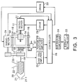
- FIG. 3 the rotation of an injection servomotor 11 is transmitted to a ball screw 12.
- a nut 13 is fixed on a pressure plate 14 and is moved forward and backward by rotation of the ball screw 12.
- the pressure plate 14 is movable along four guide bars 15 and 16 (only two are shown in the figure) fixed on a base frame (not shown). Forward and backward movement of the pressure plate 14 is transmitted to a screw 20 via a bearing 17, a load cell 18, and an injection shaft 19.
- the screw 20 is disposed in a heating cylinder 21 such that rotary and axial movement can be achieved.
- the heating cylinder 21 includes a hopper 22 for feeding a resin to a position corresponding to a rear portion of the screw 20.
- Rotary motion of a servomotor 24 for rotating the screw 20 is transmitted to the injection shaft 19 via a connecting member 23 which may be a belt, pulleys, etc.
- the servomotor 24 rotates the injection shaft 19 which in turn rotates the screw 20.
- the screw 20 rotates and moves backwards in the heating cylinder 21, so that a molten resin is moved in a feed forward direction and that the molten resin is stored in front of the screw 20, that is, at a nozzle 21-1 side in the heating cylinder 21.
- the backward movement of the screw 20 is caused by pressure due to a gradual increase in the amount of molten resin stored in front of the screw 20.
- the forward movement of the screw 20 in the heating cylinder 21 is caused by driving force from the injection servomotor 11, so that the molten resin stored in front of the screw 20 is forced into and is pressurized in a metal mold.
- the force required for pressing the molten resin is detected by the load cell 18 as an injection pressure.
- the detected injection pressure is amplified by a load cell amplifier 25 and is fed into a controller 26.
- the pressure plate 14 has a position detector 27 to detect the amount of movement of the screw 20.
- the detecting signal outputted from the position detector 27 is amplified by a position detector amplifier 28 and is fed into the controller 26.
- the controller 26 outputs current (torque) instruction values corresponding to the respective processes and based on values preset by a display/setting unit 33 via a man-machine controller 34.
- the current instruction values are fed to a drive 29 and a drive 30.
- the drive 29 controls a current for driving the servomotor 11 to control an output torque of the servomotor 11.
- the drive 30 controls a current for driving the servomotor 24 to control the number of revolutions of the servomotor 24.
- the servomotor 11 and the servomotor 24 comprise encoders 31 and 32, respectively, to detect the number of revolutions.
- the number of revolutions detected by the encoders 31 and 32 is fed to the controller 26. In particular, the number of revolutions detected by the encoder 32 is used to determine the number of revolutions of the screw 20.
- the control method according to the present invention is applied to the injection molding machine shown in Fig. 3.
- the controller 26 receives the detecting signals from the position detector 27 and the encoders 31 and 32, controls the servomotors 11 and 24, and also controls the plasticization/measuring process and injecting process. Also, the controller 26 carries out the control method according to the present invention, which will be described hereinbelow.
- the screw 20 is rotated and moved backwards after completion of the measuring process or the injecting process.
- the screw 20 is moved linearly backwards relative to the feed forward direction of the molten resin.
- a synchronization ratio S of the rotation speed at which a flight 20a of the screw 20 does not apparently move relative to a backward speed V of the screw 20 is defined as 100 %.
- the synchronization ratio S can be set from 0 % to an arbitrary percentage, and each of settings to 100 % or more and setting to less than 100 % has the following purpose:
- the synchronization ratio S is less than 100 %: This setting is performed for the purpose of dragging the resin backwards with the flight of the screw 20, as shown in Fig. 4A.
- the synchronization ratio S is 100 % or more: this setting is performed for the purpose of feeding the resin forward, that is, for measuring the resin, as shown in Fig. 4B. However, the measuring is performed at a constant rotation speed irrespective of the pressure of the resin when the screw moves backwards at a constant speed, and is different from a conventional control for maintaining the pressure of the resin constant. This operation prevents generation of a low density region during backward movement of the screw 20.
- the flight moves by 20 mm on each rotation of the screw.
- the flight of the screw 20 is apparently at a fixed position when the screw 20 rotates one turn per one second.
- the direction of the rotation depends on the direction of the rotation of the flight in the screw 20. if the flight in the screw 20 is the clockwise direction, the direction of the rotation is the clockwise direction.
- Rotation speed R (rpm) [Backward speed V (mm/sec)]/Pitch P (mm) of the flight] ⁇ 60
- a consistent state of the resin can be controlled during the backward movement of the screw 20.
- the present invention is not limited to the motor-driven injection molding machine shown in Fig. 3, and may also be applied to a hydraulic injection molding machine. In this case, a hydraulic piston mechanism is used instead of the injection servomotor 11.
- the screw when the screw is moved backward, the screw is rotated at an arbitrary rotation speed, and thus, the density distribution of the resin in the heating cylinder, particularly at the nose portion of the screw, can be sufficiently controlled so that variations in the weight of the molded products can be reduced.
- the invention relates to a method for controlling an injection molding machine including a heating cylinder and a screw disposed in the heating cylinder, and performing a plasticization/ measuring process and an injection process, said method comprising steps of: defining a synchronization ratio S of a rotation speed of the screw; and moving the screw backwards while rotating it after completion of the measuring process or the injection process.
Landscapes
- Engineering & Computer Science (AREA)
- Manufacturing & Machinery (AREA)
- Mechanical Engineering (AREA)
- Injection Moulding Of Plastics Or The Like (AREA)
Applications Claiming Priority (2)
| Application Number | Priority Date | Filing Date | Title |
|---|---|---|---|
| JP2000348194 | 2000-11-15 | ||
| JP2000348194A JP3686328B2 (ja) | 2000-11-15 | 2000-11-15 | 射出成形機の制御方法 |
Publications (2)
| Publication Number | Publication Date |
|---|---|
| EP1207032A1 true EP1207032A1 (de) | 2002-05-22 |
| EP1207032B1 EP1207032B1 (de) | 2008-08-13 |
Family
ID=18821815
Family Applications (1)
| Application Number | Title | Priority Date | Filing Date |
|---|---|---|---|
| EP01127324A Expired - Lifetime EP1207032B1 (de) | 2000-11-15 | 2001-11-15 | Verfahren zum Steuern einer Spritzgiessmaschine geeignet zum Reduzieren der Gewichtsänderungen von Formkörpern |
Country Status (9)
| Country | Link |
|---|---|
| US (1) | US20020056934A1 (de) |
| EP (1) | EP1207032B1 (de) |
| JP (1) | JP3686328B2 (de) |
| KR (1) | KR100466521B1 (de) |
| CN (1) | CN1199778C (de) |
| AT (1) | ATE404348T1 (de) |
| DE (1) | DE60135292D1 (de) |
| SG (1) | SG96661A1 (de) |
| TW (1) | TW515744B (de) |
Cited By (1)
| Publication number | Priority date | Publication date | Assignee | Title |
|---|---|---|---|---|
| WO2003039839A1 (de) * | 2001-11-07 | 2003-05-15 | Krauss-Maffei Kunststofftechnik Gmbh | Verfahren zum regeln des dosiervorgangs einer spritzgiessmaschine |
Families Citing this family (8)
| Publication number | Priority date | Publication date | Assignee | Title |
|---|---|---|---|---|
| TWI233388B (en) * | 2003-03-13 | 2005-06-01 | Sumitomo Heavy Industries | Molding device and control method thereof |
| US7582083B2 (en) * | 2004-05-10 | 2009-09-01 | Boston Scientific Scimed, Inc. | Probe based low temperature lesion formation apparatus, systems and methods |
| US8119044B1 (en) * | 2010-11-07 | 2012-02-21 | Noriyuki Akasaka | Device and method for plasticization control of electric injection molding machine |
| CN102101352B (zh) * | 2010-12-22 | 2013-08-07 | 浙江大学 | 一种注塑成型制品重量无模型控制方法 |
| KR101273164B1 (ko) * | 2011-01-27 | 2013-06-14 | 엘에스엠트론 주식회사 | 사출성형기의 스크류 제어 방법 |
| JP5893466B2 (ja) * | 2012-03-28 | 2016-03-23 | 住友重機械工業株式会社 | 射出成形機 |
| US11872737B2 (en) * | 2020-07-30 | 2024-01-16 | Promess, Inc. | System and apparatus for injection molding |
| CN114834014B (zh) * | 2022-04-20 | 2024-06-11 | 西安拽亘弗莱工业自动化科技有限公司 | 一种应用于两级注塑的均速熔胶方法 |
Citations (9)
| Publication number | Priority date | Publication date | Assignee | Title |
|---|---|---|---|---|
| JPS61121921A (ja) * | 1984-11-19 | 1986-06-09 | Japan Steel Works Ltd:The | 射出成形機の計量速度制御方法 |
| JPS63262219A (ja) * | 1987-04-20 | 1988-10-28 | Motomaro Aoki | 電動式射出装置における材料射出方法 |
| JPH02121819A (ja) * | 1988-10-31 | 1990-05-09 | Mitsubishi Heavy Ind Ltd | 射出成形機のスクリュ回転制御装置 |
| JPH0477228A (ja) * | 1990-07-18 | 1992-03-11 | Sumitomo Heavy Ind Ltd | 射出成形機のスクリュー駆動装置 |
| JPH04207989A (ja) * | 1990-11-30 | 1992-07-29 | Fanuc Ltd | 駆動モータをトルク特性可変にした射出成形機 |
| JPH09286049A (ja) * | 1996-04-24 | 1997-11-04 | Japan Steel Works Ltd:The | 射出成形機の計量方法およびその装置 |
| JP2000015675A (ja) * | 1998-07-01 | 2000-01-18 | Teijin Ltd | 薄肉板状成形品の射出成形方法 |
| EP1072387A2 (de) * | 1999-07-30 | 2001-01-31 | Sumitomo Heavy Industries, Ltd. | Verfahren und Vorrichtung zum Nullabgleichen eines Drucksensores bei einer Spritzgiessmaschine |
| EP1077123A2 (de) * | 1999-07-23 | 2001-02-21 | Sumitomo Heavy Industries, Ltd. | Spritzgiessvorrichtung und Verfahren zu ihrer Steuerung |
Family Cites Families (5)
| Publication number | Priority date | Publication date | Assignee | Title |
|---|---|---|---|---|
| US3941534A (en) * | 1971-11-01 | 1976-03-02 | Hunkar Laboratories, Inc. | Injection molding control system |
| KR900001932A (ko) * | 1988-07-04 | 1990-02-27 | 조태형 | 댐의 콘크리트 차수벽 시공장치 |
| JPH04336222A (ja) * | 1991-05-14 | 1992-11-24 | Sumitomo Jukikai Plast Mach Kk | 射出成形機のノズル内樹脂圧による制御方法 |
| KR970002297A (ko) * | 1995-06-08 | 1997-01-24 | 권문구 | 트롤리 와이어용 통전 내마모 시험기 |
| JP2000012675A (ja) * | 1998-06-23 | 2000-01-14 | Matsushita Electron Corp | 半導体装置の製造方法 |
-
2000
- 2000-11-15 JP JP2000348194A patent/JP3686328B2/ja not_active Expired - Fee Related
-
2001
- 2001-10-17 TW TW090125661A patent/TW515744B/zh not_active IP Right Cessation
- 2001-11-06 KR KR10-2001-0068790A patent/KR100466521B1/ko active IP Right Grant
- 2001-11-06 CN CNB011368888A patent/CN1199778C/zh not_active Expired - Fee Related
- 2001-11-14 US US09/987,345 patent/US20020056934A1/en not_active Abandoned
- 2001-11-15 SG SG200107035A patent/SG96661A1/en unknown
- 2001-11-15 DE DE60135292T patent/DE60135292D1/de not_active Expired - Lifetime
- 2001-11-15 EP EP01127324A patent/EP1207032B1/de not_active Expired - Lifetime
- 2001-11-15 AT AT01127324T patent/ATE404348T1/de active
Patent Citations (9)
| Publication number | Priority date | Publication date | Assignee | Title |
|---|---|---|---|---|
| JPS61121921A (ja) * | 1984-11-19 | 1986-06-09 | Japan Steel Works Ltd:The | 射出成形機の計量速度制御方法 |
| JPS63262219A (ja) * | 1987-04-20 | 1988-10-28 | Motomaro Aoki | 電動式射出装置における材料射出方法 |
| JPH02121819A (ja) * | 1988-10-31 | 1990-05-09 | Mitsubishi Heavy Ind Ltd | 射出成形機のスクリュ回転制御装置 |
| JPH0477228A (ja) * | 1990-07-18 | 1992-03-11 | Sumitomo Heavy Ind Ltd | 射出成形機のスクリュー駆動装置 |
| JPH04207989A (ja) * | 1990-11-30 | 1992-07-29 | Fanuc Ltd | 駆動モータをトルク特性可変にした射出成形機 |
| JPH09286049A (ja) * | 1996-04-24 | 1997-11-04 | Japan Steel Works Ltd:The | 射出成形機の計量方法およびその装置 |
| JP2000015675A (ja) * | 1998-07-01 | 2000-01-18 | Teijin Ltd | 薄肉板状成形品の射出成形方法 |
| EP1077123A2 (de) * | 1999-07-23 | 2001-02-21 | Sumitomo Heavy Industries, Ltd. | Spritzgiessvorrichtung und Verfahren zu ihrer Steuerung |
| EP1072387A2 (de) * | 1999-07-30 | 2001-01-31 | Sumitomo Heavy Industries, Ltd. | Verfahren und Vorrichtung zum Nullabgleichen eines Drucksensores bei einer Spritzgiessmaschine |
Non-Patent Citations (12)
| Title |
|---|
| DATABASE WPI Week 198629, Derwent World Patents Index; AN 1986-187680, XP002190378 * |
| DATABASE WPI Week 198849, Derwent World Patents Index; AN 1988-350334, XP002190376 * |
| DATABASE WPI Week 199217, Derwent World Patents Index; AN 1992-136594, XP002190377 * |
| DATABASE WPI Week 199237, Derwent World Patents Index; AN 1992-303407, XP002190375 * |
| DATABASE WPI Week 200052, Derwent World Patents Index; AN 2000-560258, XP002190374 * |
| PATENT ABSTRACTS OF JAPAN vol. 010, no. 311 (M - 528) 23 October 1986 (1986-10-23) * |
| PATENT ABSTRACTS OF JAPAN vol. 013, no. 055 (M - 795) 8 February 1989 (1989-02-08) * |
| PATENT ABSTRACTS OF JAPAN vol. 014, no. 351 (M - 1003) 30 July 1990 (1990-07-30) * |
| PATENT ABSTRACTS OF JAPAN vol. 016, no. 290 (M - 1272) 26 June 1992 (1992-06-26) * |
| PATENT ABSTRACTS OF JAPAN vol. 016, no. 550 (E - 1292) 19 November 1992 (1992-11-19) * |
| PATENT ABSTRACTS OF JAPAN vol. 1998, no. 03 27 February 1998 (1998-02-27) * |
| PATENT ABSTRACTS OF JAPAN vol. 2000, no. 04 31 August 2000 (2000-08-31) * |
Cited By (1)
| Publication number | Priority date | Publication date | Assignee | Title |
|---|---|---|---|---|
| WO2003039839A1 (de) * | 2001-11-07 | 2003-05-15 | Krauss-Maffei Kunststofftechnik Gmbh | Verfahren zum regeln des dosiervorgangs einer spritzgiessmaschine |
Also Published As
| Publication number | Publication date |
|---|---|
| JP2002144391A (ja) | 2002-05-21 |
| CN1353040A (zh) | 2002-06-12 |
| KR20020037681A (ko) | 2002-05-22 |
| CN1199778C (zh) | 2005-05-04 |
| TW515744B (en) | 2003-01-01 |
| EP1207032B1 (de) | 2008-08-13 |
| DE60135292D1 (de) | 2008-09-25 |
| ATE404348T1 (de) | 2008-08-15 |
| JP3686328B2 (ja) | 2005-08-24 |
| US20020056934A1 (en) | 2002-05-16 |
| SG96661A1 (en) | 2003-06-16 |
| KR100466521B1 (ko) | 2005-01-15 |
Similar Documents
| Publication | Publication Date | Title |
|---|---|---|
| EP0965428A2 (de) | Verfahren zum Absenken des Druckes beim Plastifizierungs- und Dosiervorgang für eine motorangetriebene Spritzgiessmaschine | |
| US4879077A (en) | Control method of injection molding machine | |
| JP3440406B2 (ja) | 射出成形機の背圧制御方法及び背圧制御装置 | |
| EP1207032A1 (de) | Verfahren und Vorrichtung zum Steuern einer Spritzgiessmaschine geeignet zum Reduzieren der Gewichtsänderungen von Formkörpern | |
| US6416694B1 (en) | Injection controlling method for an injection molding machine | |
| US9339961B2 (en) | Metering controller for injection molding machine | |
| EP1163993B1 (de) | Spritzgiessmaschine und Verfahren zum Steuern der Position der Schnecke | |
| KR100405834B1 (ko) | 성형품의 중량변동을 줄일 수 있는 사출성형기의 제어장치 및 제어방법 | |
| US20150140148A1 (en) | Controller for injection molding machine | |
| US9744705B2 (en) | Controller for injection molding machine | |
| KR100436963B1 (ko) | 사출성형기의 스크루 구동 제어방법 | |
| JP3336296B2 (ja) | 射出装置及びその制御方法 | |
| JP5052246B2 (ja) | 射出成形機 | |
| JP4319966B2 (ja) | 射出成形機の制御方法 | |
| JP3749783B2 (ja) | 射出成形機 | |
| JP3661993B2 (ja) | 射出成形機の制御方法 | |
| JP4040989B2 (ja) | 射出成形機およびその制御方法ならびに制御プログラム | |
| JP5001073B2 (ja) | 射出成形機および成形制御方法 | |
| WO2022196280A1 (ja) | 射出成形機の制御方法及び射出成形機 | |
| JPH0435144Y2 (de) | ||
| JP3321437B2 (ja) | 射出装置及びその制御方法 | |
| JP3535063B2 (ja) | 射出成形機 | |
| JP2001079909A (ja) | 射出装置及びその制御方法 | |
| JP2001353762A (ja) | 射出装置 | |
| JP2004345282A (ja) | 射出成形機の制御方法 |
Legal Events
| Date | Code | Title | Description |
|---|---|---|---|
| PUAI | Public reference made under article 153(3) epc to a published international application that has entered the european phase |
Free format text: ORIGINAL CODE: 0009012 |
|
| AX | Request for extension of the european patent |
Free format text: AL;LT;LV;MK;RO;SI |
|
| 17P | Request for examination filed |
Effective date: 20021121 |
|
| AKX | Designation fees paid |
Designated state(s): AT CH DE FR GB IT LI |
|
| 17Q | First examination report despatched |
Effective date: 20031015 |
|
| GRAP | Despatch of communication of intention to grant a patent |
Free format text: ORIGINAL CODE: EPIDOSNIGR1 |
|
| GRAS | Grant fee paid |
Free format text: ORIGINAL CODE: EPIDOSNIGR3 |
|
| GRAA | (expected) grant |
Free format text: ORIGINAL CODE: 0009210 |
|
| AK | Designated contracting states |
Kind code of ref document: B1 Designated state(s): AT CH DE FR GB IT LI |
|
| REG | Reference to a national code |
Ref country code: GB Ref legal event code: FG4D |
|
| REG | Reference to a national code |
Ref country code: CH Ref legal event code: NV Representative=s name: E. BLUM & CO. AG PATENT- UND MARKENANWAELTE VSP Ref country code: CH Ref legal event code: EP |
|
| REF | Corresponds to: |
Ref document number: 60135292 Country of ref document: DE Date of ref document: 20080925 Kind code of ref document: P |
|
| PLBE | No opposition filed within time limit |
Free format text: ORIGINAL CODE: 0009261 |
|
| STAA | Information on the status of an ep patent application or granted ep patent |
Free format text: STATUS: NO OPPOSITION FILED WITHIN TIME LIMIT |
|
| 26N | No opposition filed |
Effective date: 20090514 |
|
| GBPC | Gb: european patent ceased through non-payment of renewal fee |
Effective date: 20081115 |
|
| REG | Reference to a national code |
Ref country code: FR Ref legal event code: ST Effective date: 20090731 |
|
| PG25 | Lapsed in a contracting state [announced via postgrant information from national office to epo] |
Ref country code: GB Free format text: LAPSE BECAUSE OF NON-PAYMENT OF DUE FEES Effective date: 20081115 |
|
| PG25 | Lapsed in a contracting state [announced via postgrant information from national office to epo] |
Ref country code: FR Free format text: LAPSE BECAUSE OF NON-PAYMENT OF DUE FEES Effective date: 20081130 |
|
| PGFP | Annual fee paid to national office [announced via postgrant information from national office to epo] |
Ref country code: CH Payment date: 20131112 Year of fee payment: 13 Ref country code: AT Payment date: 20131028 Year of fee payment: 13 Ref country code: DE Payment date: 20131113 Year of fee payment: 13 |
|
| PGFP | Annual fee paid to national office [announced via postgrant information from national office to epo] |
Ref country code: IT Payment date: 20131113 Year of fee payment: 13 |
|
| REG | Reference to a national code |
Ref country code: DE Ref legal event code: R119 Ref document number: 60135292 Country of ref document: DE |
|
| REG | Reference to a national code |
Ref country code: CH Ref legal event code: PL |
|
| REG | Reference to a national code |
Ref country code: AT Ref legal event code: MM01 Ref document number: 404348 Country of ref document: AT Kind code of ref document: T Effective date: 20141115 |
|
| PG25 | Lapsed in a contracting state [announced via postgrant information from national office to epo] |
Ref country code: CH Free format text: LAPSE BECAUSE OF NON-PAYMENT OF DUE FEES Effective date: 20141130 Ref country code: LI Free format text: LAPSE BECAUSE OF NON-PAYMENT OF DUE FEES Effective date: 20141130 |
|
| PG25 | Lapsed in a contracting state [announced via postgrant information from national office to epo] |
Ref country code: AT Free format text: LAPSE BECAUSE OF NON-PAYMENT OF DUE FEES Effective date: 20141115 |
|
| PG25 | Lapsed in a contracting state [announced via postgrant information from national office to epo] |
Ref country code: DE Free format text: LAPSE BECAUSE OF NON-PAYMENT OF DUE FEES Effective date: 20150602 |
|
| PG25 | Lapsed in a contracting state [announced via postgrant information from national office to epo] |
Ref country code: IT Free format text: LAPSE BECAUSE OF NON-PAYMENT OF DUE FEES Effective date: 20141115 |